EP3412393A2 - Dispositifs et procédé de chanfreinage d'une pièce à denture intérieure - Google Patents
Dispositifs et procédé de chanfreinage d'une pièce à denture intérieure Download PDFInfo
- Publication number
- EP3412393A2 EP3412393A2 EP18172850.2A EP18172850A EP3412393A2 EP 3412393 A2 EP3412393 A2 EP 3412393A2 EP 18172850 A EP18172850 A EP 18172850A EP 3412393 A2 EP3412393 A2 EP 3412393A2
- Authority
- EP
- European Patent Office
- Prior art keywords
- workpiece
- holder
- toothing
- chamfering
- tool holder
- Prior art date
- Legal status (The legal status is an assumption and is not a legal conclusion. Google has not performed a legal analysis and makes no representation as to the accuracy of the status listed.)
- Granted
Links
Images



Classifications
-
- B—PERFORMING OPERATIONS; TRANSPORTING
- B23—MACHINE TOOLS; METAL-WORKING NOT OTHERWISE PROVIDED FOR
- B23F—MAKING GEARS OR TOOTHED RACKS
- B23F19/00—Finishing gear teeth by other tools than those used for manufacturing gear teeth
- B23F19/10—Chamfering the end edges of gear teeth
- B23F19/102—Chamfering the end edges of gear teeth by milling
- B23F19/104—Chamfering the end edges of gear teeth by milling the tool being a hob
-
- B—PERFORMING OPERATIONS; TRANSPORTING
- B23—MACHINE TOOLS; METAL-WORKING NOT OTHERWISE PROVIDED FOR
- B23F—MAKING GEARS OR TOOTHED RACKS
- B23F1/00—Making gear teeth by tools of which the profile matches the profile of the required surface
-
- B—PERFORMING OPERATIONS; TRANSPORTING
- B23—MACHINE TOOLS; METAL-WORKING NOT OTHERWISE PROVIDED FOR
- B23F—MAKING GEARS OR TOOTHED RACKS
- B23F19/00—Finishing gear teeth by other tools than those used for manufacturing gear teeth
- B23F19/10—Chamfering the end edges of gear teeth
- B23F19/102—Chamfering the end edges of gear teeth by milling
-
- B—PERFORMING OPERATIONS; TRANSPORTING
- B23—MACHINE TOOLS; METAL-WORKING NOT OTHERWISE PROVIDED FOR
- B23F—MAKING GEARS OR TOOTHED RACKS
- B23F21/00—Tools specially adapted for use in machines for manufacturing gear teeth
- B23F21/005—Tools specially adapted for use in machines for manufacturing gear teeth with plural tools on a common axis
-
- B—PERFORMING OPERATIONS; TRANSPORTING
- B23—MACHINE TOOLS; METAL-WORKING NOT OTHERWISE PROVIDED FOR
- B23F—MAKING GEARS OR TOOTHED RACKS
- B23F21/00—Tools specially adapted for use in machines for manufacturing gear teeth
- B23F21/12—Milling tools
- B23F21/16—Hobs
-
- B—PERFORMING OPERATIONS; TRANSPORTING
- B23—MACHINE TOOLS; METAL-WORKING NOT OTHERWISE PROVIDED FOR
- B23F—MAKING GEARS OR TOOTHED RACKS
- B23F23/00—Accessories or equipment combined with or arranged in, or specially designed to form part of, gear-cutting machines
- B23F23/02—Loading, unloading or chucking arrangements for workpieces
- B23F23/04—Loading or unloading arrangements
-
- B—PERFORMING OPERATIONS; TRANSPORTING
- B23—MACHINE TOOLS; METAL-WORKING NOT OTHERWISE PROVIDED FOR
- B23F—MAKING GEARS OR TOOTHED RACKS
- B23F23/00—Accessories or equipment combined with or arranged in, or specially designed to form part of, gear-cutting machines
- B23F23/02—Loading, unloading or chucking arrangements for workpieces
- B23F23/06—Chucking arrangements
-
- B—PERFORMING OPERATIONS; TRANSPORTING
- B23—MACHINE TOOLS; METAL-WORKING NOT OTHERWISE PROVIDED FOR
- B23Q—DETAILS, COMPONENTS, OR ACCESSORIES FOR MACHINE TOOLS, e.g. ARRANGEMENTS FOR COPYING OR CONTROLLING; MACHINE TOOLS IN GENERAL CHARACTERISED BY THE CONSTRUCTION OF PARTICULAR DETAILS OR COMPONENTS; COMBINATIONS OR ASSOCIATIONS OF METAL-WORKING MACHINES, NOT DIRECTED TO A PARTICULAR RESULT
- B23Q39/00—Metal-working machines incorporating a plurality of sub-assemblies, each capable of performing a metal-working operation
- B23Q39/02—Metal-working machines incorporating a plurality of sub-assemblies, each capable of performing a metal-working operation the sub-assemblies being capable of being brought to act at a single operating station
-
- B—PERFORMING OPERATIONS; TRANSPORTING
- B23—MACHINE TOOLS; METAL-WORKING NOT OTHERWISE PROVIDED FOR
- B23Q—DETAILS, COMPONENTS, OR ACCESSORIES FOR MACHINE TOOLS, e.g. ARRANGEMENTS FOR COPYING OR CONTROLLING; MACHINE TOOLS IN GENERAL CHARACTERISED BY THE CONSTRUCTION OF PARTICULAR DETAILS OR COMPONENTS; COMBINATIONS OR ASSOCIATIONS OF METAL-WORKING MACHINES, NOT DIRECTED TO A PARTICULAR RESULT
- B23Q39/00—Metal-working machines incorporating a plurality of sub-assemblies, each capable of performing a metal-working operation
- B23Q39/04—Metal-working machines incorporating a plurality of sub-assemblies, each capable of performing a metal-working operation the sub-assemblies being arranged to operate simultaneously at different stations, e.g. with an annular work-table moved in steps
- B23Q39/048—Metal-working machines incorporating a plurality of sub-assemblies, each capable of performing a metal-working operation the sub-assemblies being arranged to operate simultaneously at different stations, e.g. with an annular work-table moved in steps the work holder of a work station transfers directly its workpiece to the work holder of a following work station
-
- B—PERFORMING OPERATIONS; TRANSPORTING
- B23—MACHINE TOOLS; METAL-WORKING NOT OTHERWISE PROVIDED FOR
- B23Q—DETAILS, COMPONENTS, OR ACCESSORIES FOR MACHINE TOOLS, e.g. ARRANGEMENTS FOR COPYING OR CONTROLLING; MACHINE TOOLS IN GENERAL CHARACTERISED BY THE CONSTRUCTION OF PARTICULAR DETAILS OR COMPONENTS; COMBINATIONS OR ASSOCIATIONS OF METAL-WORKING MACHINES, NOT DIRECTED TO A PARTICULAR RESULT
- B23Q2230/00—Special operations in a machine tool
- B23Q2230/006—Machining both ends of a workpiece consecutively
Definitions
- the present invention relates to an apparatus and a method for chamfering at least one end edge of the toothing of an internally toothed workpiece, with at least one rotatably mounted workpiece holder for receiving the workpiece and at least one rotatably mounted tool holder for receiving at least one Anfasfräsers.
- the chamfer cutter may be a chamfer-cut cutter.
- edges of the teeth are often still provided with special protective chamfers.
- the chamfering of the workpieces is usually done by specially adapted deburring tools following the production of the teeth on the workpiece blank.
- Anfasrea there are several methods of the prior art. In mass production, especially the methods are Druckentgraten according to the DE 8328237 A and chamfering frets according to the DE 20320294 A as well as the DE 202007016740 A used.
- the DE 20320294 A shows the Anfasfräsegraten with a so-called Chamfer-cut router.
- a chamfer-cut milling cutter is a disc-shaped deburring tool 11, which has cutting teeth 12 and spur grooves on the circumference, preferably with the same circumferential distance in each case.
- the cutting teeth have a helical course in the circumferential direction.
- the Chamfer-Cut-cutter is multi-functional, with one tooth per gear. However, the formed on the front in the direction of rotation of the teeth cutting edges are on a common circle.
- the above chamfering methods are usually used for chamfering workpieces with external teeth, for example by the deburring tool is clamped together with the milling tool on the same mandrel and engaged after the milling operation with the edges of the toothing.
- chamfering milling station in which chamfer cutters, in particular Chamfer cut milling cutters, are used as the only tools in the tool spindle.
- the device shown there for chamfering internal gears can also be arranged within an internally toothed workpiece.
- the device should be arranged at larger internal gears within the toothed workpiece on a fixed console in the center of the machine table or a support on the machine table and thus serve the chamfering of internal gears.
- Internal gears with smaller Inner diameter of the space for this embodiment is no longer sufficient.
- the object of the invention is to provide an improved apparatus and an improved method for chamfering the frontal edges of the toothing of an internally toothed workpiece.
- the present invention comprises a device for chamfering at least one end edge of the toothing of an internally toothed workpiece, wherein the device has at least one rotatably mounted workpiece holder for receiving the workpiece and at least one rotatably mounted tool holder for receiving a chamfer cutter, in particular a chamfer cutter. Milling cutter.
- the first aspect of the present invention is characterized in that the tool holder is arranged next to a workpiece received in the workpiece holder and / or can be arranged, wherein a chamfer cutter received in the tool holder can be arranged by means of a tool pin in the center opening of the workpiece formed by the internal toothing to be engaged with an edge of the internal teeth on the top and / or bottom of the workpiece.
- the inventors of the present invention have recognized that it is not necessary for chamfering an internal toothing to arrange the entire device with which the chamfering takes place within the central opening formed by the internal toothing. Furthermore, the inventors of the present invention have realized that it is not even necessary to arrange the tool holder in this area.
- the tool holder can be arranged next to the workpiece, and only the Anfasfräser be arranged by means of a tool mandrel in the inner region of the workpiece.
- the tool mandrel runs from an outer region of the workpiece to the inner region of the workpiece, starting from the tool holder on the upper side and / or lower side of the internally toothed annular region of the workpiece.
- the present invention requires only a relatively long tool mandrel so that it extends beyond the internally toothed annular region of the workpiece in order to arrange the chamfer cutter in the inner region of the workpiece.
- the length of the tool mandrel from the tool holder to at least one chamfer cutter arranged on the tool mandrel is at least 10% of the inner radius of the internal toothing of the workpiece, preferably more than 20% and at least 30%. In a particularly preferred embodiment, the length is more than 40%. If several Anfasfräser are provided on the mandrel, these dimensions are preferred for the length of the mandrel between the tool holder and the first, the tool holder facing Anfasfräser. More preferably, the length of the mandrel between two chamfers arranged on the mandrel is at least 10% of the inner radius of the internal toothing of the workpiece, preferably more than 20%, more preferably at least 30% or 40%.
- the tool holder can be arranged on a machining head arranged next to or above the workpiece holder and can be moved relative thereto by means of the workpiece holder.
- the machining head is arranged on a machine stand next to or above the workpiece holder.
- the machine stand can be arranged on a machine bed, which also carries the workpiece holder.
- the machining head has a machine axis for moving the tool holder in the axial direction of the workpiece holder and / or a machine axis for moving the tool holder in a direction perpendicular to the axis of rotation of the workpiece holder and / or to the axis of rotation of the tool holder.
- the machining head may have a pivot axis for pivoting the tool holder about a pivot axis perpendicular to the axis of rotation of the tool holder and / or to the axis of rotation of the workpiece holder and / or a machine axis for shifting the tool holder in the direction of its axis of rotation.
- the chamfer cutter arranged on the tool mandrel is accessible from a lower side and / or upper side.
- the tool holder can be arranged on a machine stand via a machining head, the machining head preferably extending perpendicular to the axis of rotation of the workpiece holder and / or the axis of rotation of the tool holder extending away from the machine frame. In particular, this extends the axis of rotation of the tool holder at a certain distance from the machine frame.
- the tool holder can be arranged on a machining head in such a way that it extends parallel to the front of the machine stand facing the workpiece holder.
- the device according to the invention can be constructed such that the annular region of the internally toothed workpiece, which is chamfered by the chamfering cutter, extends in a region between the machine stand and the axis of rotation of the tool holder below or above the tool mandrel.
- the device according to the invention has a sensor for threading and / or centering the Anfasfräsers in the internal toothing of the workpiece.
- Such a sensor is particularly necessary when the device according to the invention is designed as a stand-alone arrangement or the workpiece whose edges are to be chamfered, previously in the manufacture of the toothing in one Another workpiece holder was arranged and, for example, is transported via a workpiece changer for workpiece holder of the device according to the invention, since in this case the position of the toothing is not known relative to the device.
- a non-contact sensor It is preferably a non-contact sensor.
- an inductive sensor and / or an optical sensor can be used.
- the sensor for threading and / or centering the Anfasfräsers is preferably arranged on a separate arm, via which it is moved into the internal toothing.
- the arm for the sensor is arranged together with the tool holder on a machining head of the device and / or can be moved over the same machine axes.
- an arrangement of the sensor outside the toothing would be conceivable, for example, when using optical sensors.
- the present invention comprises a device for chamfering at least one front edge of the toothing of an internally toothed workpiece, the device having a first rotatably mounted workpiece holder for receiving the workpiece and at least one rotatably mounted tool holder for receiving at least one chamfer cutter, in particular a chamfer cutter. Cut router, has.
- the second aspect of the present invention is characterized in that the device has a second rotatably mounted workpiece holder for receiving the workpiece.
- the edge of the toothing on a first end side of the tool is anfasbearbeitbar while the workpiece is received in the first workpiece holder, and the edge on the second end face of the workpiece anfasbearbeitbar while the workpiece is received in the second workpiece holder.
- the inventors of the present invention have recognized that the chamfering of the edges of the toothing on both the top and on the bottom of a received in a workpiece holder, internally toothed workpiece is particularly complicated, since in particular the edge of the toothing on the tool holder facing side of the workpiece is extremely difficult to access.
- this problem is solved in that two workpiece holders are provided, so that in each case the edge can be chamfered, which is arranged on the side facing away from the workpiece holder and therefore easily accessible.
- the device according to the invention preferably has a machining head which can be moved over machine axes and which serves for chamfering the edges of the toothing both on the first and on the second end face. Therefore, the same machining head can be used to machine both a workpiece received in the first workpiece holder and a workpiece received in the second workpiece holder. In particular, the same machine axes can be used to perform chamfering.
- the tool holder of the device according to the invention is arranged on the machining head and can be moved by its machine axes.
- the chamfering of the edges of the toothing on the first and the second end side can take place via the same chamfering cutter or via a plurality of chamfering cutters received in the same tool holder.
- the chamfering of the edges of the toothing takes place on the first and second end faces of the workpiece via two separate chamfered cutters mounted on the same tool mandrel.
- the device according to the invention preferably has a device for changing the workpiece from the first workpiece holder to the second workpiece holder and / or from the second workpiece holder to the first workpiece holder on.
- the workpiece can be changed to the second workpiece fixture to chamfer the edges of the toothing on the second end face.
- the change takes place such that the second end face of the workpiece faces the first workpiece holder, while the workpiece is received therein, and the first end side of the workpiece faces the second workpiece holder, while the workpiece is arranged in this, so that the respective other end faces are accessible and can be edited.
- the device for changing the workpiece can be made available in that one of the two workpiece holders is movable so that it can grip a workpiece received in the other workpiece holder.
- a workpiece changer may be provided for moving the workpiece from one workpiece holder to the other workpiece holder.
- the rotational position of the workpiece in the workpiece transfer electronically transmitted from the first workpiece holder to the second workpiece holder, so that after the workpiece transfer, the rotational position is known again.
- a renewed threading process may no longer be necessary to correctly position the chamfering tool for chamfering the toothing on the second end face of the workpiece.
- the two workpiece holders are arranged on two opposite sides of a work area or can be arranged.
- the workpiece is, depending on which workpiece holder it is received, with its first or second end face facing the work area.
- the chamfering cutter or chisels are arranged in the working area in order to machine the respective edges of the toothing on the end faces facing the working area.
- the two workpiece holders have parallel axes of rotation.
- the two workpiece holder are arranged coaxially.
- the one workpiece holder is particularly preferably movable in the direction of its axis of rotation to the other workpiece holder in order to take over the workpiece.
- the first and second aspects of the present invention are initially independent of each other and can each be implemented separately.
- the two aspects of the present invention are combined in one device.
- the chamfering of a workpiece accommodated in the first and / or second workpiece holder of a device according to the second aspect of the present invention can be carried out according to the first aspect.
- the tool holder is arranged next to the two workpiece holders and / or can be arranged, wherein at least one chamfer can be arranged by means of a tool mandrel above the center opening formed by the internal teeth of the workpiece, if this is arranged in the first workpiece holder, with an edge of the toothing on the top of the workpiece to be engaged.
- a chamfering cutter can be arranged by means of a tool mandrel below the central opening formed by the internal toothing, if this is arranged in the second workpiece holder, in order to be brought into engagement with an edge of the toothing on the underside of the workpiece.
- the same tool holder is used for chamfering the edges of the toothing on top and bottom.
- chamfering cutters preferably arranged on the same tool mandrel, are used to machine the edges of the toothing on the upper side and lower side.
- the direction of rotation can be chosen so that both the chamfering of the edges of the toothing on the top, as well as chamfering the edges of the teeth on the bottom of a processing from the end faces into the teeth takes place, or the direction of rotation is chosen so that in each case a processing of the edges of the toothing takes place with a cutting direction of the toothing in the direction of the end faces.
- This has the advantage that during chamfering remaining burrs remain either only on the end faces, or only within the toothing.
- the direction of rotation of the respective workpiece holder is adjusted according to the direction of rotation of the chamfer cutter.
- the same chamfer cutter can be used to machine the edges of the toothing on top and bottom.
- it can be brought into engagement in the same radial region of the workpiece with the edge of the toothing on top and bottom sides.
- this has the disadvantage that in each case different cutting directions in the chamfering of the edges of the toothing on top and bottom exist.
- the chamfering cutter is therefore preferably brought into engagement with an edge region of the toothing on a first side of the workpiece with respect to the axis of rotation of the workpiece and after the workpiece has been changed into the second workpiece holder by moving the tool holder in a direction of rotation of the workpiece second radial direction with a radially opposite edge portion of the toothing on the second side of the workpiece engaged.
- This has the advantage that in turn results in the same cutting direction with respect to the workpiece on both sides. In this case, the direction of rotation of the workpiece holders must be adjusted when changing the intervention points.
- the chamfer cutter or chisels arranged on a tool mandrel are accessible from two sides in order to be able to be engaged in each case with one edge of the workpiece. In particular, they are accessible both from the top, as well as from the bottom.
- the devices according to the invention are usually used in mass production and in particular mass production.
- the machining of the workpieces and thus also the Anfasvon takes place in this case automatically by the control of the device.
- the devices according to the invention therefore preferably have a control for automatic control of the machine axes of the device for chamfering the edge of the toothing on at least one and preferably on both end faces of a workpiece.
- control of the device is preferably programmed such that the devices according to the invention automatically perform the steps described above with regard to their mode of operation and / or application.
- the controller has in particular a microprocessor and a memory in which a control program for controlling the device is stored, which is processed by the microprocessor.
- the present invention initially provides a device as described in more detail above, which is suitable for receiving a Anfasfräsers and in particular a Chamfer-Cut router in the tool holder and to carry out the applications described above.
- the present invention also includes a device, as described above, in which at least one chamfering cutter is received in the tool holder, or in which, in the case of a plurality of tool holders, chamfering tools are respectively accommodated therein.
- chamfer cut milling cutters are accommodated in the tool holder or the tool holders.
- the present invention further relates to a gear machining center having a device as described above, a gear cutting machine and a workpiece changer.
- the gear cutting machine is preferably a machine for machining internal gears, in particular a milling machine or a gear cutting machine or a skiving machine.
- the gear processing and the chamfering of the workpieces in the Veryakbearbeitungstechnik clock time-parallel.
- workpieces toothed by the gear cutting machine are further transported via the workpiece changer to the apparatus according to the present invention for chamfering in order to be chamfered while the next workpiece is already being toothed on the gear cutting machine.
- chamfering of the workpiece between a roughing step and a finishing step is conceivable, for which the workpiece is preferably moved from the gear cutting machine to the device according to the invention and back again.
- the workpiece changer is a ring automation, wherein furthermore preferably the chamfering device according to the invention and the gear cutting machine are arranged at different angular positions of the ring automation.
- the gear cutting machine and the device according to the invention preferably have separate workpiece holders.
- the workpiece changer changes in this case, a workpiece after the gear processing of the gear cutting machine from the local workpiece holder for workpiece holder of the inventive device for chamfering.
- the gear machining center may also have a plurality of workpiece holders, in which the workpieces for the gear processing and chamfering remain.
- the workpiece holders are preferably moved from the gear cutting machine to the device according to the invention and / or vice versa.
- the workpiece changer is preferably used to place workpieces from an external transport path or other processing stations on the workpiece holder or workpiece holders and remove them.
- the device according to the invention can also be designed as a separate machine.
- this toothed workpieces receives from a transport route and / or automation to this Anfaszube cases.
- the correspondingly machined workpieces are then preferably transferred back to a transport line and / or automation.
- the present invention also includes corresponding methods in addition to the devices according to the invention.
- the present invention also encompasses those methods which have been described above with respect to the devices according to the invention.
- the present invention in the form of the first aspect comprises a method for chamfering at least one end edge of the toothing of an internally toothed workpiece by a chamfer-cut milling cutter, in particular a chamfer-cut milling cutter, received in a rotatably mounted tool holder.
- the method according to the invention is characterized in that the tool holder is arranged next to a workpiece accommodated in a workpiece holder and the chamfer cutter received in the tool holder is arranged via a tool mandrel in the center opening formed by the internal toothing, with an edge of the toothing on the upper side and / or underside of the workpiece to be engaged.
- the method according to the invention preferably takes place as has already been described in more detail above with regard to the device according to the first aspect of the present invention.
- the method according to the invention can be carried out using such a device.
- the present invention further comprises a method for chamfering at least one frontal edge of the toothing of an internally toothed workpiece by a chamfer cutters, in particular a chamfer-cut milling cutter, received in a rotatably mounted tool holder.
- a chamfer cutters in particular a chamfer-cut milling cutter
- the edge of the toothing on a first end side of the workpiece is machined while the workpiece is received in a first workpiece holder, and the edge of the toothing on a second end face of the workpiece is machined while the workpiece in a second workpiece holder is added.
- this method also takes place as already described in more detail above with regard to the device according to the invention according to the second aspect.
- the method is carried out using such a device.
- the present invention further includes the use of a chamfering cutter, in particular the use of a chamfer-cut milling cutter, for carrying out one of the methods according to the invention, as described above.
- the present invention comprises the use of a chamfering cutter, in particular a chamfer-cut milling cutter, in one of the devices according to the invention, as described above.
- the methods and devices according to the invention are preferably used for chamfering the edges of spur gears.
- the workpieces according to the invention are preferably gearwheels, in particular gearwheels with internal teeth.
- gears with an internal toothing preferably have a ring shape, wherein the internal toothing is arranged on the inner annular surface.
- Chamfering preferably takes place via a Chamfer-Cut milling cutter.
- the Chamfer-cut router can be designed as the deburring tool, which in the DE 10330474 A1 is described.
- the chamfering is carried out by means of the Chamfer-cut milling cutter, as also in the DE 10330474 A1 is described for the deburring process.
- the Chamfer-Cut milling cutter is preferably not clamped on the same tool mandrel with the tool used to produce the toothing, but in its own tool holder, preferably as a single tool in its own tool holder.
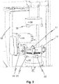
- a device according to the invention for chamfering the edges of the toothing of an internally toothed workpiece 21 is shown.
- the device has a tool holder 10, in which at least one chamfering cutter 11, 11 'is received via a tool mandrel 13. Furthermore, a workpiece holder 20 is provided, via which the workpiece 21 is received, so that the edge of the toothing on at least one end face of the workpiece 21 by a recorded in the tool holder 10 Anfasfräser 11, 11 'can be chamfered.
- the chamfer cutter is preferably brought into engagement with the edge and the rotational movement of the tool holder 10 is synchronized with the rotational movement of the workpiece holder 20 such that the chamfer cutter machines the edge of the toothing of the workpiece.
- the tool holder 10 is arranged outside the workpiece 21, but the chamfering cutter 11 or 11 'for chamfering the edge region is arranged in the region of the center opening of the workpiece 21 by means of the tool mandrel 13. As in particular from Fig. 2 can be seen, this extends the tool mandrel 13, starting from the arranged next to the workpiece holder 20 tool holder 10 over the annular toothed portion of the workpiece away in the region of the center opening of the workpiece, so that the Anfasfräser is arranged in this area and processed from there the edge.
- the Anfasfräser 11 is arranged for this purpose in an area above the central bore, the tool holder in an area next to and slightly above the workpiece holder 20. Since the teeth 12 of the Anfasfräsers 11 protrude beyond the radius of the tool mandrel 13, they can in the center bore of the workpiece 21 dive to edit the edges of the gearing.
- the workpiece 21 is directed with its bottom to the workpiece holder 20, while the edge of the toothing is toothed on the top by the Anfasfräser 11.
- the Anfasfräser engages from above into the center opening of the workpiece 21.
- the tool mandrel 13 extends above the top of the workpiece 21 over the annular region of the workpiece.
- the tool holder 10 is disposed on a machining head 40 and can be moved over the machine axes relative to the workpiece holder 20.
- the machining head 40 is arranged on a machine stand 55 in the exemplary embodiment.
- This machine stand 55 is arranged within a frame 50, which is provided next to the workpiece holder 20 on a common console 60 with which the unit is mounted on the machine bed.
- the machine axes for moving the machining head 40 comprise an X3 axis, with which the machining head can be moved in a direction perpendicular to the rotational axis C3 of the workpiece holder 20 and to the rotational axis B3 of the tool holder 10, and a Z3 axis, via which the machining head in a direction parallel to the axis of rotation C3 of the workpiece holder 20 can be moved.
- a pivot axis A3 is provided, via which the machining head about an axis which is perpendicular to the axes of rotation B3 and C3 of the tool holder 10 and the workpiece holder 20, can be pivoted.
- a shift axis V3 is provided, which allows a displacement of the tool holder 10 in the direction of its axis of rotation B3.
- a Y3 axis would also be conceivable over which the machining head 40 can be moved in a direction perpendicular to the X3 axis and to the Z3 axis.
- the axes X3, Z3 and V3 are preferably linear axes, which can be realized, for example, via slides.
- the tool holder 10 is arranged together with its drive 14 on the machining head 40.
- the arrangement is such that the axis of rotation B3 of the tool holder extends at a distance from the workpiece facing front side of the machine stand 55, in a plane which is perpendicular to the X3 axis.
- Such an embodiment of the machining head and the workpiece holder is also common in machining heads for externally toothed workpieces.
- the engagement with the workpiece does not take place on the side of the chamfer cutter facing away from the machine stand 55, but on the side of the chamfer cutter facing the machine stand 55.
- the annular region of the workpiece 21 to be machined must extend in the radial direction with respect to the axis of rotation C3 of the workpiece holder on the side of the chamfer cutter 11 facing the machine frame 55.
- the annular region of the workpiece 21 to be machined may extend between a front side of the machine stand 55 facing the workpiece and the chamfering cutter.
- the mandrel 13 can also be made so long that the Anfasfräser 11 and 11 'in the direction of the V3 axis in front of a side surface of the machine stand 55 is. As a result, the annular region of the workpiece 21 to be machined can extend next to the machine stand 55.
- the device according to the invention preferably has a sensor (not shown in the exemplary embodiment) for threading and / or centering the chamfer cutter into the internal toothing of the workpiece. It is preferably a non-contact sensor. For example, an inductive sensor and / or an optical sensor can be used.
- the sensor for threading and / or centering the Anfasfräsers is preferably arranged on a separate arm, via which it can be moved into the internal toothing of the recorded in the workpiece holder 20 workpiece 21 into it.
- the arm for the sensor on the machining head 40 and / or the machine stand 55 of the device is arranged and can be moved over the machine axes.
- the above-described embodiment of the present invention according to the first aspect is initially only for processing the edge on a first end side of the recorded in the workpiece holder 20 workpiece, on the side facing away from the workpiece holder 20 end face, in the embodiment of the top.
- the second aspect can be realized independently of the first aspect.
- the device according to the invention comprises, in addition to the first workpiece holder 20, a second workpiece holder 30 in order to be able to machine the edges of the toothing both on the upper side and on the lower side of the workpiece.
- the edge of the toothing on the top of the workpiece 21 is chamfered while this in the first workpiece holder 20 is received, and the edge of the toothing on the underside of the workpiece 21 anfasverierebearbeitet while this is arranged in the second workpiece holder 30. Accordingly, the workpiece 21 is received in the first workpiece holder 20, that its underside is directed to the workpiece holder 20, while the top is freely accessible, and so received in the second workpiece holder 30 that its top is directed to the second workpiece holder 30 and the bottom is freely accessible.
- the two workpiece holders are arranged opposite one another, so that one processing head is sufficient to machine both a workpiece which is received in the first workpiece holder 20 and a workpiece which is received in the second workpiece holder 30.
- the workpiece After machining the edge of the toothing on one side of the toothing, the workpiece is changed from one workpiece holder to the other workpiece holder. Which page is edited first, can be chosen arbitrarily.
- the axes of rotation C3 and C4 of the first and the second workpiece holder 20 and 30 are arranged in parallel and aligned with each other.
- the change of the workpiece from one workpiece holder to the other workpiece holder is in the in Fig. 1 to 6 illustrated embodiment realized in that the second workpiece holder 30 via a traverse Z4, which runs parallel to its axis of rotation C4, is movable.
- the second workpiece holder 30 can be placed on a recorded in the first workpiece holder 20 workpiece 21 be to grab this and lift from the first workpiece holder 20.
- the workpiece holders 20 and 30 have clamping jaws 22 and 32 for this purpose, which can act simultaneously on the workpiece 21. After the second workpiece holder 30 has been lowered onto the workpiece 21 and the workpiece has been secured on the second workpiece holder 30 via the clamping jaws 32, therefore, the clamping jaws 22 of the first workpiece holder 20 are loosened to release the workpiece 21.
- the position of the toothing of the workpiece 21 received in the second workpiece holder relative to the second workpiece holder 30 is preferably calculated from the known position of the toothing of the workpiece 21 relative to the first workpiece holder 20 and the relative position between the first and the second workpiece holder 20 and 30 during the transfer , A sensor for threading and / or centering the Anfasfräsers in the toothing of the second workpiece holder 30 received workpiece 21 is therefore not necessary.
- the Z4-axis is realized in the embodiment via a carriage 70 which is movable on a guide 80 and the second workpiece holder 30 carries.
- the device according to the invention is designed such that a workpiece received in the first or second workpiece holder is processed in each case according to the first aspect of the toothing.
- Anfasfräser is arranged over the tool mandrel in the region of the center opening of the workpiece, wherein the mandrel above or below the workpiece from an outer region to the inner region of the workpiece.
- a workpiece 21 is received in the workpiece holder 20, while the Anfasfräser 11 and 11 'are arranged together with the tool holder 10 next to the workpiece holder 20 or so far above the workpiece holder 20 that they do not form interference edges for changing the workpiece.
- the chamfering cutter 11 is then brought into engagement with the edge portion of the internal teeth on the upper side of the workpiece 21 received in the workpiece holder 20 by moving the X3 and / or Z3 axis. If the chamfering cutter 11 has previously been arranged next to the workpiece holder 20, the entire processing head is moved toward the workpiece holder 20 via the X3 axis until the chamfering cutter 11 is above the center opening of the internally toothed workpiece 21. Then, the chamfering cutter is brought into engagement with the edge by lowering the machining head via the Z3 axis to work it in the toothed manner. Was the chamfer 11 already above the workpiece holder 20, it only requires the lowering of the Z3 axis.
- the A3 axis and the V3 axis may be used to adjust the exact position of the chamfer cutter relative to the workpiece 21.
- the machining head After chamfering the edge of the gearing on top of the workpiece, the machining head is raised above the Z3 axis so that the chamfering mill 11 is moved out of the center opening of the gear and then by moving the machining head about the X3 or V3 axis moved next to the workpiece holder 20.
- the second workpiece holder 30 is lowered to take over the workpiece 21.
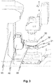
- chamfering of the edge of the toothing on the underside of the workpiece 21, as shown in FIG Fig. 4 and 5 is shown in more detail.
- the chamfering machining is done here in the same way according to the first aspect of the present invention as previously described with regard to the chamfering of the edge on the top of the workpiece described opposite direction of rotation.
- the position of the machining head with respect to the greater distance of Anfasfräsers 11 'to the tool holder 10 will be adjusted accordingly, in particular by methods on the V3 axis.
- a Chamfer-cut milling cutter is preferably designed as a chamfering cutter in the context of the present invention.
- a chamfer-cut cutter is a disc-shaped deburring tool 11 which Having cutting teeth 12 and Spahnnuten at the periphery, preferably with the same circumferential distance.
- the profile of the cutting teeth 12 of the Chamfer-Cut milling cutter is designed specifically for chamfering the edge of an internal toothing.
- the cutting teeth have a helical course in the circumferential direction.
- the Chamfer-Cut-cutter is multi-functional, with one tooth per gear.
- the formed on the front in the direction of rotation of the teeth cutting edges are on a common circle.
- the rotational movement between the Chamfer-Cut cutter and the workpiece is synchronized so that in each case a tooth coincides with a tooth gap of the workpiece.
- the chamfer-cut cutter 11 For chamfering the chamfer-cut cutter 11 is brought into a position as in Fig. 5 is reproduced. During the machining of the end edges of the tooth grooves, the workpiece 21 and the chamfer-cut milling cutter 11 rotate in a predetermined speed ratio, so that in each case a cutting tooth 12 processes the end edges of a toothed groove. It is understood that the chamfer-cut milling cutter 11 and the teeth 12 are designed according to the parameters of the toothing of the workpiece 21, so that the desired engagement with the front edges of the tooth grooves can take place.
- the device according to the invention preferably has a control by which the axes of rotation of the tool holder and the workpiece holder as well as the machine axes for adjusting the relative position between the tool holder and the workpiece holder are controlled.
- the controller preferably controls the device according to the invention automatically. In particular, she is there Programmed so that the methods described above or methods of use of the device according to the invention are carried out automatically.
- the inventive device for chamfering workpieces can be used in a machining center in combination with a gear cutting machine, which previously generates the toothing on the workpiece.
- the gear cutting machine can be, for example, a gear cutting machine for machining internal gears or a gear shaping machine or a skiving machine, which are particularly suitable for producing internal gears.
- the gear cutting machine and the device according to the invention may each have separate workpiece holders, wherein a workpiece changer is provided in order to transport the workpieces from the gear cutting machine to the chamfering device according to the invention.
- the workpieces can remain clamped on a workpiece holder and transported on the workpiece holder from the gear cutting machine to the device according to the invention.
- Fig. 6 an embodiment of a gear center is shown, which comprises a device 1 according to the invention according to the embodiment described in more detail above.
- the workpiece holder 20 is fixedly assigned in the embodiment of the device according to the invention, and is fitted via a ring loader 3 with workpieces.
- gear cutting machine is arranged at a different angular position 2, for example at an angle of 90 ° to the device 1 according to the invention, relative to the ring loader 3.
- the ring loader 3 can therefore transport toothed workpieces to the device according to the invention in the gear cutting machine.
- the workpieces can also be transported back to the gear cutting machine, for example, to allow chamfering between a roughing step and a finishing step.
- the rail 80 via which the Z4-axis is provided for moving the second workpiece holder 30, is arranged in the exemplary embodiment on a machine stand, which also carries the ring loader 3.
- the machining head 40 is arranged in a position opposite to the ring loader.
Landscapes
- Engineering & Computer Science (AREA)
- Mechanical Engineering (AREA)
- Gear Processing (AREA)
- Milling, Drilling, And Turning Of Wood (AREA)
Applications Claiming Priority (1)
| Application Number | Priority Date | Filing Date | Title |
|---|---|---|---|
| DE102017112416.0A DE102017112416A1 (de) | 2017-06-06 | 2017-06-06 | Vorrichtung und Verfahren zum Anfasen eines innenverzahnten Werkstücks |
Publications (3)
| Publication Number | Publication Date |
|---|---|
| EP3412393A2 true EP3412393A2 (fr) | 2018-12-12 |
| EP3412393A3 EP3412393A3 (fr) | 2019-03-13 |
| EP3412393B1 EP3412393B1 (fr) | 2020-08-19 |
Family
ID=62196451
Family Applications (1)
| Application Number | Title | Priority Date | Filing Date |
|---|---|---|---|
| EP18172850.2A Active EP3412393B1 (fr) | 2017-06-06 | 2018-05-17 | Dispositifs et procédé de chanfreinage d'une pièce à denture intérieure |
Country Status (5)
| Country | Link |
|---|---|
| US (1) | US10857608B2 (fr) |
| EP (1) | EP3412393B1 (fr) |
| JP (1) | JP6810099B2 (fr) |
| CN (1) | CN108994393B (fr) |
| DE (1) | DE102017112416A1 (fr) |
Cited By (1)
| Publication number | Priority date | Publication date | Assignee | Title |
|---|---|---|---|---|
| CN112222541A (zh) * | 2020-10-28 | 2021-01-15 | 宜昌长机科技有限责任公司 | 一种中型插齿机夹具交换工作台机构及操作方法 |
Families Citing this family (8)
| Publication number | Priority date | Publication date | Assignee | Title |
|---|---|---|---|---|
| DE102015104242A1 (de) * | 2015-03-20 | 2016-09-22 | Profilator Gmbh & Co. Kg | Verzahnungsverfahren mit Zahnnachbearbeitung |
| CN109604736B (zh) * | 2019-01-23 | 2020-05-26 | 河南科技大学 | 一种利用加工中心加工螺旋锥齿轮的方法 |
| CN110293382B (zh) * | 2019-07-04 | 2021-04-23 | 山东润通齿轮集团有限公司 | 齿轮加工机床的多功能集成式加工工艺 |
| CN110293381B (zh) * | 2019-07-04 | 2021-04-20 | 轻工业西安机械设计研究院有限公司 | 齿轮的插齿加工工艺 |
| CN111992819A (zh) * | 2020-09-08 | 2020-11-27 | 安徽天渥智能制造有限公司 | 一种齿轮生产倒角装置 |
| JP7089563B2 (ja) * | 2020-09-30 | 2022-06-22 | 株式会社タンガロイ | 面取り加工方法及び面取り加工装置 |
| CN112620827A (zh) * | 2020-12-08 | 2021-04-09 | 安徽三山机械制造有限公司 | 一种回转齿轮的加工锻造工装 |
| DE102024120994A1 (de) * | 2024-07-24 | 2026-01-29 | Liebherr-Verzahntechnik Gmbh | Vorrichtung zur Anfasbearbeitung |
Citations (5)
| Publication number | Priority date | Publication date | Assignee | Title |
|---|---|---|---|---|
| DE8328237U1 (de) | 1983-10-01 | 1984-07-05 | Carl Hurth Maschinen- und Zahnradfabrik GmbH & Co, 8000 München | Vorrichtung zum entgraten oder brechen der stirnseitigen zahnkanten von zahnraedern |
| DE20320294U1 (de) | 2003-07-05 | 2004-04-15 | Fette Gmbh | Vorrichtung zur Herstellung eines Zahnrads |
| DE10330474A1 (de) | 2003-07-05 | 2005-02-10 | Fette Gmbh | Verfahren, Vorrichtung und Werkzeug zum Anfasen der Stirnkanten der Zahnnuten eines Zahnrades |
| DE202007016740U1 (de) | 2006-12-02 | 2008-03-13 | Maschinenfabrik Rausch Gmbh & Co. Kg | Vorrichtung zum Entgraten eines Werkstücks |
| DE102013015240A1 (de) | 2013-03-28 | 2014-10-02 | Liebherr-Verzahntechnik Gmbh | Vorrichtung und Verfahren zum Anfasen eines Werkstücks |
Family Cites Families (38)
| Publication number | Priority date | Publication date | Assignee | Title |
|---|---|---|---|---|
| US2114627A (en) * | 1934-12-26 | 1938-04-19 | Gleason Works | Machine for producing gears |
| US2135819A (en) * | 1936-09-15 | 1938-11-08 | W C Lipe Inc | Adjustable chamfering tool and holder |
| DE736920C (de) * | 1940-12-18 | 1943-07-01 | Otto Ortlinghaus Soehne | Vorrichtung zum Entgraten der Stirnkanten gezahnter Werkstuecke |
| US2665612A (en) | 1951-04-26 | 1954-01-12 | Theodor Klatte | Device for producing internally toothed ring gears and the like |
| DE1627379A1 (de) | 1967-04-08 | 1970-05-14 | Zahnradfabrik Friedrichshafen | Zahnraeder-Waelzfraesmaschine |
| US3673660A (en) | 1969-11-13 | 1972-07-04 | Joseph J Osplack | Method of producing internal gearing |
| US3714740A (en) | 1970-08-24 | 1973-02-06 | F Steinhardt | Gear deburring device |
| CH556207A (de) | 1973-03-26 | 1974-11-29 | Maag Zahnraeder & Maschinen Ag | Verfahren und maschine zur herstellung von schraegverzahnten evolventenstirnraedern mit innenverzahnung. |
| US3931754A (en) | 1974-11-12 | 1976-01-13 | Kabushiki Kaisha Komatsu Seisakusho | Skiving cutter device for use in cutting internal spur gear |
| US4130967A (en) | 1977-06-14 | 1978-12-26 | Bjr Machine & Gear | Precision gear crown grinding machine |
| DE4122461C1 (fr) | 1991-07-06 | 1992-07-30 | Praewema Werkzeugmaschinenfabrik Gmbh, 3440 Eschwege, De | |
| DE19515043C2 (de) * | 1995-04-24 | 1997-02-27 | Traub Ag | Drehmaschine mit zwischen Werkzeugträgern austauschbaren Werkzeughaltern |
| US6227775B1 (en) | 1999-03-17 | 2001-05-08 | Arnold F. Klammer | Internal gears and splines and milling method and apparatus for manufacturing same |
| US6633965B2 (en) | 2001-04-07 | 2003-10-14 | Eric M. Rentschler | Memory controller with 1×/M× read capability |
| JP2006224228A (ja) * | 2005-02-16 | 2006-08-31 | Kashifuji:Kk | 歯車加工装置 |
| JP4839479B2 (ja) * | 2005-05-12 | 2011-12-21 | 株式会社 神崎高級工機製作所 | 内歯シェービング装置 |
| DE202005011790U1 (de) | 2005-07-22 | 2005-10-20 | Gleason-Pfauter Maschinenfabrik Gmbh | Verzahnmaschine, insbesondere Kegelrad-Verzahnmaschine, mit einer Vorrichtung zum Anfasen/Entgraten der Kanten eines Werkstückes |
| DE102008016497A1 (de) | 2008-03-31 | 2009-10-01 | Liebherr-Verzahntechnik Gmbh | Bearbeitungskopf |
| DE102009019433A1 (de) | 2009-04-29 | 2010-11-04 | Gleason-Pfauter Maschinenfabrik Gmbh | Verfahren und Vorrichtung zum Bearbeiten der Zahnkanten stirnverzahnter Werkräder |
| CN201618892U (zh) * | 2010-02-08 | 2010-11-03 | 马鞍山方圆回转支承股份有限公司 | 重型齿轮倒角机 |
| JP5308388B2 (ja) * | 2010-03-31 | 2013-10-09 | 三菱重工業株式会社 | 歯車加工機械 |
| DE102011118312A1 (de) * | 2011-11-11 | 2013-05-16 | Liebherr-Verzahntechnik Gmbh | Verfahren und Vorrichtung zur Bearbeitung von Zahnkanten |
| JP5835139B2 (ja) * | 2012-02-24 | 2015-12-24 | アイシン・エィ・ダブリュ株式会社 | 回転加工機及び回転加工方法 |
| DE102012008296A1 (de) | 2012-04-26 | 2013-10-31 | Klingelnberg Gmbh | Vorrichtung und Verfahren zum Erzeugen, Bearbeiten und/oder Prüfen profiltragender Segmente |
| JP6212876B2 (ja) * | 2013-02-15 | 2017-10-18 | アイシン精機株式会社 | 歯車加工方法及び歯車加工用カッター |
| CN103273142A (zh) | 2013-06-04 | 2013-09-04 | 南京工业大学 | 极坐标内外齿复合高效双端面倒棱机 |
| CN203449088U (zh) * | 2013-08-21 | 2014-02-26 | 吉林省金沙数控机床有限公司 | 正倒立组合式数控机床 |
| DE102013021184A1 (de) | 2013-12-17 | 2015-06-18 | Gleason-Pfauter Maschinenfabrik Gmbh | Verfahren zum Be- und Entladen eines Werkstückes mit Innenverzahnung und Be- und Entladevorrichtung |
| DE102014008475B4 (de) | 2014-06-05 | 2023-02-23 | Gleason-Pfauter Maschinenfabrik Gmbh | Verfahren zum Bearbeiten eines Werkstücks, Werkzeuganordnung und Verzahnungsmaschine |
| EP2954967B1 (fr) * | 2014-06-11 | 2019-08-07 | Klingelnberg AG | Procédé et dispositif de chanfreinage frontal d'une denture d'une pièce à usiner |
| DE102014014132A1 (de) * | 2014-09-30 | 2016-05-25 | Liebherr-Verzahntechnik Gmbh | Verfahren und Vorrichtung zum Anfasen und Entgraten verzahnter Werkstücke |
| EP3200948B1 (fr) * | 2014-10-02 | 2021-09-15 | The Gleason Works | Fraise-mère comprenant des dents de coupe multi-tours et procédé de fabrication d'un engrenage en utilisant une fraise-mère |
| DE102015008964A1 (de) | 2015-07-10 | 2017-01-12 | Liebherr-Verzahntechnik Gmbh | Verfahren zum Abrichten eines Werkzeuges |
| DE102015012190B3 (de) * | 2015-09-17 | 2017-01-12 | Emag Holding Gmbh | Wälzfräsmaschine zum Herstellen und Entgraten von Verzahnungen |
| DE102017107999A1 (de) * | 2017-04-13 | 2018-10-18 | Klingelnberg Ag | Entgratvorrichtung sowie CNC-Verzahnmaschine mit einer solchen Entgratvorrichtung |
| DE102017112450A1 (de) * | 2017-06-06 | 2018-12-06 | Liebherr-Verzahntechnik Gmbh | Vorrichtung und Verfahren zum Anfasen eines innenverzahnten Werkstücks |
| DE102018108632A1 (de) * | 2018-04-11 | 2019-10-17 | Liebherr-Verzahntechnik Gmbh | Vorrichtung zur Anfasbearbeitung eines Werkstücks |
| DE102018108622A1 (de) * | 2018-04-11 | 2019-10-17 | Liebherr-Verzahntechnik Gmbh | Vorrichtung zur Anfasbearbeitung eines Werkstücks |
-
2017
- 2017-06-06 DE DE102017112416.0A patent/DE102017112416A1/de not_active Withdrawn
-
2018
- 2018-05-17 EP EP18172850.2A patent/EP3412393B1/fr active Active
- 2018-05-25 JP JP2018100569A patent/JP6810099B2/ja active Active
- 2018-06-05 CN CN201810569135.8A patent/CN108994393B/zh active Active
- 2018-06-06 US US16/001,872 patent/US10857608B2/en active Active
Patent Citations (5)
| Publication number | Priority date | Publication date | Assignee | Title |
|---|---|---|---|---|
| DE8328237U1 (de) | 1983-10-01 | 1984-07-05 | Carl Hurth Maschinen- und Zahnradfabrik GmbH & Co, 8000 München | Vorrichtung zum entgraten oder brechen der stirnseitigen zahnkanten von zahnraedern |
| DE20320294U1 (de) | 2003-07-05 | 2004-04-15 | Fette Gmbh | Vorrichtung zur Herstellung eines Zahnrads |
| DE10330474A1 (de) | 2003-07-05 | 2005-02-10 | Fette Gmbh | Verfahren, Vorrichtung und Werkzeug zum Anfasen der Stirnkanten der Zahnnuten eines Zahnrades |
| DE202007016740U1 (de) | 2006-12-02 | 2008-03-13 | Maschinenfabrik Rausch Gmbh & Co. Kg | Vorrichtung zum Entgraten eines Werkstücks |
| DE102013015240A1 (de) | 2013-03-28 | 2014-10-02 | Liebherr-Verzahntechnik Gmbh | Vorrichtung und Verfahren zum Anfasen eines Werkstücks |
Cited By (2)
| Publication number | Priority date | Publication date | Assignee | Title |
|---|---|---|---|---|
| CN112222541A (zh) * | 2020-10-28 | 2021-01-15 | 宜昌长机科技有限责任公司 | 一种中型插齿机夹具交换工作台机构及操作方法 |
| CN112222541B (zh) * | 2020-10-28 | 2021-11-02 | 宜昌长机科技有限责任公司 | 一种中型插齿机夹具交换工作台机构及操作方法 |
Also Published As
| Publication number | Publication date |
|---|---|
| JP2019022925A (ja) | 2019-02-14 |
| CN108994393B (zh) | 2022-02-11 |
| US10857608B2 (en) | 2020-12-08 |
| US20180345393A1 (en) | 2018-12-06 |
| CN108994393A (zh) | 2018-12-14 |
| EP3412393A3 (fr) | 2019-03-13 |
| DE102017112416A1 (de) | 2018-12-06 |
| JP6810099B2 (ja) | 2021-01-06 |
| EP3412393B1 (fr) | 2020-08-19 |
Similar Documents
| Publication | Publication Date | Title |
|---|---|---|
| EP3412393B1 (fr) | Dispositifs et procédé de chanfreinage d'une pièce à denture intérieure | |
| EP3552743B1 (fr) | Dispositif et procédé de chanfreinage d'une pièce dentée | |
| EP3412395B1 (fr) | Dispositifs et procédé de chanfreinage d'une pièce à denture intérieure | |
| EP1910003B1 (fr) | Machine universelle pour usinage avant traitement de pignons coniques et procede correspondant | |
| DE4101749C2 (fr) | ||
| EP3388179A1 (fr) | Procédé d'usinage de denture d'une pièce à usiner | |
| EP1577041B1 (fr) | Machine et procédé correspondant de taillage de roues dentées coniques pour la chanfreinage et l'ébavaurage des extrémités de dents des roues dentées coniques | |
| EP2786824A2 (fr) | Dispositifs et procédé de chanfreinage d'une pièce | |
| DE102011118312A1 (de) | Verfahren und Vorrichtung zur Bearbeitung von Zahnkanten | |
| EP1850994A1 (fr) | Procede et dispositif d'usinage avant traitement de roues coniques | |
| EP3636374B1 (fr) | Machine à tailler et procédé de fabrication d'une pièce dentée | |
| DE3420531A1 (de) | Drehmaschine | |
| EP3349934A1 (fr) | Procédé et dispositif de fabrication et d'ébavurage de dentures | |
| DE4236866A1 (de) | Drehmaschine | |
| DE102015012908B3 (de) | Verfahren und Vorrichtung zum Herstellen und Entgraten von Verzahnungen | |
| DE102015012190B3 (de) | Wälzfräsmaschine zum Herstellen und Entgraten von Verzahnungen | |
| DE10330909B4 (de) | Werkzeugmaschine und Verfahren zur spanabhebenden Bearbeitung von Werkstücken | |
| DE102013224311B3 (de) | Vorrichtung zum Bearbeiten von Werkstücken | |
| DE2038842C3 (de) | Bearbeitungszentrum mit einer um eine horizontale Achse rotierbaren Speichertrommel | |
| EP0453875B1 (fr) | Machine pour le travail du métal par enlèvement de copeaux | |
| DE19911156C2 (de) | Drehmaschine zur Bearbeitung von wellenförmigen Werkstücken | |
| EP1251980A1 (fr) | Procede et dispositif de traitement de parois de soufflure de coquilles de coulage continu | |
| EP4615652A1 (fr) | Procédé d'usinage de denture avec chanfreinage ultérieur | |
| DE10127973C2 (de) | Vorrichtung zum Fräsen von Rastnuten und Schaltanschlägen an den Zahnflanken einzelner Zähne von Schiebemuffen für Schaltgetriebe | |
| DE10109117C1 (de) | Entgratvorrichtung für Kegelräder |
Legal Events
| Date | Code | Title | Description |
|---|---|---|---|
| PUAI | Public reference made under article 153(3) epc to a published international application that has entered the european phase |
Free format text: ORIGINAL CODE: 0009012 |
|
| STAA | Information on the status of an ep patent application or granted ep patent |
Free format text: STATUS: THE APPLICATION HAS BEEN PUBLISHED |
|
| AK | Designated contracting states |
Kind code of ref document: A2 Designated state(s): AL AT BE BG CH CY CZ DE DK EE ES FI FR GB GR HR HU IE IS IT LI LT LU LV MC MK MT NL NO PL PT RO RS SE SI SK SM TR |
|
| AX | Request for extension of the european patent |
Extension state: BA ME |
|
| PUAL | Search report despatched |
Free format text: ORIGINAL CODE: 0009013 |
|
| AK | Designated contracting states |
Kind code of ref document: A3 Designated state(s): AL AT BE BG CH CY CZ DE DK EE ES FI FR GB GR HR HU IE IS IT LI LT LU LV MC MK MT NL NO PL PT RO RS SE SI SK SM TR |
|
| AX | Request for extension of the european patent |
Extension state: BA ME |
|
| RIC1 | Information provided on ipc code assigned before grant |
Ipc: B23F 23/06 20060101ALI20190207BHEP Ipc: B23F 21/00 20060101AFI20190207BHEP Ipc: B23Q 39/04 20060101ALI20190207BHEP Ipc: B23F 19/10 20060101ALI20190207BHEP |
|
| STAA | Information on the status of an ep patent application or granted ep patent |
Free format text: STATUS: REQUEST FOR EXAMINATION WAS MADE |
|
| 17P | Request for examination filed |
Effective date: 20190906 |
|
| STAA | Information on the status of an ep patent application or granted ep patent |
Free format text: STATUS: EXAMINATION IS IN PROGRESS |
|
| 17Q | First examination report despatched |
Effective date: 20191023 |
|
| GRAP | Despatch of communication of intention to grant a patent |
Free format text: ORIGINAL CODE: EPIDOSNIGR1 |
|
| STAA | Information on the status of an ep patent application or granted ep patent |
Free format text: STATUS: GRANT OF PATENT IS INTENDED |
|
| INTG | Intention to grant announced |
Effective date: 20200409 |
|
| GRAS | Grant fee paid |
Free format text: ORIGINAL CODE: EPIDOSNIGR3 |
|
| GRAA | (expected) grant |
Free format text: ORIGINAL CODE: 0009210 |
|
| STAA | Information on the status of an ep patent application or granted ep patent |
Free format text: STATUS: THE PATENT HAS BEEN GRANTED |
|
| AK | Designated contracting states |
Kind code of ref document: B1 Designated state(s): AL AT BE BG CH CY CZ DE DK EE ES FI FR GB GR HR HU IE IS IT LI LT LU LV MC MK MT NL NO PL PT RO RS SE SI SK SM TR |
|
| REG | Reference to a national code |
Ref country code: CH Ref legal event code: EP Ref country code: CH Ref legal event code: NV Representative=s name: KELLER AND PARTNER PATENTANWAELTE AG, CH |
|
| REG | Reference to a national code |
Ref country code: DE Ref legal event code: R096 Ref document number: 502018002211 Country of ref document: DE |
|
| REG | Reference to a national code |
Ref country code: AT Ref legal event code: REF Ref document number: 1303381 Country of ref document: AT Kind code of ref document: T Effective date: 20200915 |
|
| REG | Reference to a national code |
Ref country code: IE Ref legal event code: FG4D Free format text: LANGUAGE OF EP DOCUMENT: GERMAN |
|
| REG | Reference to a national code |
Ref country code: CH Ref legal event code: PFA Owner name: LIEBHERR-VERZAHNTECHNIK GMBH, DE Free format text: FORMER OWNER: LIEBHERR-VERZAHNTECHNIK GMBH, DE |
|
| REG | Reference to a national code |
Ref country code: SE Ref legal event code: TRGR |
|
| REG | Reference to a national code |
Ref country code: LT Ref legal event code: MG4D |
|
| REG | Reference to a national code |
Ref country code: NL Ref legal event code: MP Effective date: 20200819 |
|
| PG25 | Lapsed in a contracting state [announced via postgrant information from national office to epo] |
Ref country code: HR Free format text: LAPSE BECAUSE OF FAILURE TO SUBMIT A TRANSLATION OF THE DESCRIPTION OR TO PAY THE FEE WITHIN THE PRESCRIBED TIME-LIMIT Effective date: 20200819 Ref country code: PT Free format text: LAPSE BECAUSE OF FAILURE TO SUBMIT A TRANSLATION OF THE DESCRIPTION OR TO PAY THE FEE WITHIN THE PRESCRIBED TIME-LIMIT Effective date: 20201221 Ref country code: NO Free format text: LAPSE BECAUSE OF FAILURE TO SUBMIT A TRANSLATION OF THE DESCRIPTION OR TO PAY THE FEE WITHIN THE PRESCRIBED TIME-LIMIT Effective date: 20201119 Ref country code: GR Free format text: LAPSE BECAUSE OF FAILURE TO SUBMIT A TRANSLATION OF THE DESCRIPTION OR TO PAY THE FEE WITHIN THE PRESCRIBED TIME-LIMIT Effective date: 20201120 Ref country code: LT Free format text: LAPSE BECAUSE OF FAILURE TO SUBMIT A TRANSLATION OF THE DESCRIPTION OR TO PAY THE FEE WITHIN THE PRESCRIBED TIME-LIMIT Effective date: 20200819 Ref country code: BG Free format text: LAPSE BECAUSE OF FAILURE TO SUBMIT A TRANSLATION OF THE DESCRIPTION OR TO PAY THE FEE WITHIN THE PRESCRIBED TIME-LIMIT Effective date: 20201119 Ref country code: FI Free format text: LAPSE BECAUSE OF FAILURE TO SUBMIT A TRANSLATION OF THE DESCRIPTION OR TO PAY THE FEE WITHIN THE PRESCRIBED TIME-LIMIT Effective date: 20200819 |
|
| PG25 | Lapsed in a contracting state [announced via postgrant information from national office to epo] |
Ref country code: LV Free format text: LAPSE BECAUSE OF FAILURE TO SUBMIT A TRANSLATION OF THE DESCRIPTION OR TO PAY THE FEE WITHIN THE PRESCRIBED TIME-LIMIT Effective date: 20200819 Ref country code: RS Free format text: LAPSE BECAUSE OF FAILURE TO SUBMIT A TRANSLATION OF THE DESCRIPTION OR TO PAY THE FEE WITHIN THE PRESCRIBED TIME-LIMIT Effective date: 20200819 Ref country code: PL Free format text: LAPSE BECAUSE OF FAILURE TO SUBMIT A TRANSLATION OF THE DESCRIPTION OR TO PAY THE FEE WITHIN THE PRESCRIBED TIME-LIMIT Effective date: 20200819 Ref country code: NL Free format text: LAPSE BECAUSE OF FAILURE TO SUBMIT A TRANSLATION OF THE DESCRIPTION OR TO PAY THE FEE WITHIN THE PRESCRIBED TIME-LIMIT Effective date: 20200819 Ref country code: IS Free format text: LAPSE BECAUSE OF FAILURE TO SUBMIT A TRANSLATION OF THE DESCRIPTION OR TO PAY THE FEE WITHIN THE PRESCRIBED TIME-LIMIT Effective date: 20201219 |
|
| PG25 | Lapsed in a contracting state [announced via postgrant information from national office to epo] |
Ref country code: EE Free format text: LAPSE BECAUSE OF FAILURE TO SUBMIT A TRANSLATION OF THE DESCRIPTION OR TO PAY THE FEE WITHIN THE PRESCRIBED TIME-LIMIT Effective date: 20200819 Ref country code: RO Free format text: LAPSE BECAUSE OF FAILURE TO SUBMIT A TRANSLATION OF THE DESCRIPTION OR TO PAY THE FEE WITHIN THE PRESCRIBED TIME-LIMIT Effective date: 20200819 Ref country code: DK Free format text: LAPSE BECAUSE OF FAILURE TO SUBMIT A TRANSLATION OF THE DESCRIPTION OR TO PAY THE FEE WITHIN THE PRESCRIBED TIME-LIMIT Effective date: 20200819 Ref country code: SM Free format text: LAPSE BECAUSE OF FAILURE TO SUBMIT A TRANSLATION OF THE DESCRIPTION OR TO PAY THE FEE WITHIN THE PRESCRIBED TIME-LIMIT Effective date: 20200819 |
|
| REG | Reference to a national code |
Ref country code: DE Ref legal event code: R097 Ref document number: 502018002211 Country of ref document: DE |
|
| PG25 | Lapsed in a contracting state [announced via postgrant information from national office to epo] |
Ref country code: AL Free format text: LAPSE BECAUSE OF FAILURE TO SUBMIT A TRANSLATION OF THE DESCRIPTION OR TO PAY THE FEE WITHIN THE PRESCRIBED TIME-LIMIT Effective date: 20200819 Ref country code: ES Free format text: LAPSE BECAUSE OF FAILURE TO SUBMIT A TRANSLATION OF THE DESCRIPTION OR TO PAY THE FEE WITHIN THE PRESCRIBED TIME-LIMIT Effective date: 20200819 |
|
| PLBE | No opposition filed within time limit |
Free format text: ORIGINAL CODE: 0009261 |
|
| STAA | Information on the status of an ep patent application or granted ep patent |
Free format text: STATUS: NO OPPOSITION FILED WITHIN TIME LIMIT |
|
| PG25 | Lapsed in a contracting state [announced via postgrant information from national office to epo] |
Ref country code: SK Free format text: LAPSE BECAUSE OF FAILURE TO SUBMIT A TRANSLATION OF THE DESCRIPTION OR TO PAY THE FEE WITHIN THE PRESCRIBED TIME-LIMIT Effective date: 20200819 |
|
| 26N | No opposition filed |
Effective date: 20210520 |
|
| PG25 | Lapsed in a contracting state [announced via postgrant information from national office to epo] |
Ref country code: SI Free format text: LAPSE BECAUSE OF FAILURE TO SUBMIT A TRANSLATION OF THE DESCRIPTION OR TO PAY THE FEE WITHIN THE PRESCRIBED TIME-LIMIT Effective date: 20200819 |
|
| PG25 | Lapsed in a contracting state [announced via postgrant information from national office to epo] |
Ref country code: LU Free format text: LAPSE BECAUSE OF NON-PAYMENT OF DUE FEES Effective date: 20210517 Ref country code: MC Free format text: LAPSE BECAUSE OF FAILURE TO SUBMIT A TRANSLATION OF THE DESCRIPTION OR TO PAY THE FEE WITHIN THE PRESCRIBED TIME-LIMIT Effective date: 20200819 |
|
| REG | Reference to a national code |
Ref country code: BE Ref legal event code: MM Effective date: 20210531 |
|
| PG25 | Lapsed in a contracting state [announced via postgrant information from national office to epo] |
Ref country code: IE Free format text: LAPSE BECAUSE OF NON-PAYMENT OF DUE FEES Effective date: 20210517 |
|
| PG25 | Lapsed in a contracting state [announced via postgrant information from national office to epo] |
Ref country code: FR Free format text: LAPSE BECAUSE OF NON-PAYMENT OF DUE FEES Effective date: 20210531 |
|
| PG25 | Lapsed in a contracting state [announced via postgrant information from national office to epo] |
Ref country code: BE Free format text: LAPSE BECAUSE OF NON-PAYMENT OF DUE FEES Effective date: 20210531 |
|
| GBPC | Gb: european patent ceased through non-payment of renewal fee |
Effective date: 20220517 |
|
| PG25 | Lapsed in a contracting state [announced via postgrant information from national office to epo] |
Ref country code: GB Free format text: LAPSE BECAUSE OF NON-PAYMENT OF DUE FEES Effective date: 20220517 |
|
| PG25 | Lapsed in a contracting state [announced via postgrant information from national office to epo] |
Ref country code: CY Free format text: LAPSE BECAUSE OF FAILURE TO SUBMIT A TRANSLATION OF THE DESCRIPTION OR TO PAY THE FEE WITHIN THE PRESCRIBED TIME-LIMIT Effective date: 20200819 |
|
| PG25 | Lapsed in a contracting state [announced via postgrant information from national office to epo] |
Ref country code: HU Free format text: LAPSE BECAUSE OF FAILURE TO SUBMIT A TRANSLATION OF THE DESCRIPTION OR TO PAY THE FEE WITHIN THE PRESCRIBED TIME-LIMIT; INVALID AB INITIO Effective date: 20180517 |
|
| PG25 | Lapsed in a contracting state [announced via postgrant information from national office to epo] |
Ref country code: MK Free format text: LAPSE BECAUSE OF FAILURE TO SUBMIT A TRANSLATION OF THE DESCRIPTION OR TO PAY THE FEE WITHIN THE PRESCRIBED TIME-LIMIT Effective date: 20200819 |
|
| REG | Reference to a national code |
Ref country code: AT Ref legal event code: MM01 Ref document number: 1303381 Country of ref document: AT Kind code of ref document: T Effective date: 20230517 |
|
| PG25 | Lapsed in a contracting state [announced via postgrant information from national office to epo] |
Ref country code: AT Free format text: LAPSE BECAUSE OF NON-PAYMENT OF DUE FEES Effective date: 20230517 |
|
| PG25 | Lapsed in a contracting state [announced via postgrant information from national office to epo] |
Ref country code: AT Free format text: LAPSE BECAUSE OF NON-PAYMENT OF DUE FEES Effective date: 20230517 |
|
| PG25 | Lapsed in a contracting state [announced via postgrant information from national office to epo] |
Ref country code: MT Free format text: LAPSE BECAUSE OF FAILURE TO SUBMIT A TRANSLATION OF THE DESCRIPTION OR TO PAY THE FEE WITHIN THE PRESCRIBED TIME-LIMIT Effective date: 20200819 |
|
| PGFP | Annual fee paid to national office [announced via postgrant information from national office to epo] |
Ref country code: DE Payment date: 20250602 Year of fee payment: 8 |
|
| PGFP | Annual fee paid to national office [announced via postgrant information from national office to epo] |
Ref country code: IT Payment date: 20250529 Year of fee payment: 8 |
|
| PGFP | Annual fee paid to national office [announced via postgrant information from national office to epo] |
Ref country code: CH Payment date: 20250601 Year of fee payment: 8 |
|
| PGFP | Annual fee paid to national office [announced via postgrant information from national office to epo] |
Ref country code: TR Payment date: 20250512 Year of fee payment: 8 |
|
| PGFP | Annual fee paid to national office [announced via postgrant information from national office to epo] |
Ref country code: CZ Payment date: 20250428 Year of fee payment: 8 |
|
| PGFP | Annual fee paid to national office [announced via postgrant information from national office to epo] |
Ref country code: SE Payment date: 20250524 Year of fee payment: 8 |
|
| PGFP | Annual fee paid to national office [announced via postgrant information from national office to epo] |
Ref country code: AT Payment date: 20260410 Year of fee payment: 5 |