EP3412827B1 - Véhicule ferroviaire destiné à l'assainissement de superstructure de voie - Google Patents
Véhicule ferroviaire destiné à l'assainissement de superstructure de voie Download PDFInfo
- Publication number
- EP3412827B1 EP3412827B1 EP18167517.4A EP18167517A EP3412827B1 EP 3412827 B1 EP3412827 B1 EP 3412827B1 EP 18167517 A EP18167517 A EP 18167517A EP 3412827 B1 EP3412827 B1 EP 3412827B1
- Authority
- EP
- European Patent Office
- Prior art keywords
- ballast
- rail vehicle
- vehicle according
- ballast bed
- new
- Prior art date
- Legal status (The legal status is an assumption and is not a legal conclusion. Google has not performed a legal analysis and makes no representation as to the accuracy of the status listed.)
- Active
Links
Images




Classifications
-
- E—FIXED CONSTRUCTIONS
- E01—CONSTRUCTION OF ROADS, RAILWAYS, OR BRIDGES
- E01B—PERMANENT WAY; PERMANENT-WAY TOOLS; MACHINES FOR MAKING RAILWAYS OF ALL KINDS
- E01B27/00—Placing, renewing, working, cleaning, or taking-up the ballast, with or without concurrent work on the track; Devices therefor; Packing sleepers
- E01B27/06—Renewing or cleaning the ballast in situ, with or without concurrent work on the track
- E01B27/08—Renewing or cleaning the ballast in situ, with or without concurrent work on the track the track having been taken-up
-
- E—FIXED CONSTRUCTIONS
- E01—CONSTRUCTION OF ROADS, RAILWAYS, OR BRIDGES
- E01B—PERMANENT WAY; PERMANENT-WAY TOOLS; MACHINES FOR MAKING RAILWAYS OF ALL KINDS
- E01B27/00—Placing, renewing, working, cleaning, or taking-up the ballast, with or without concurrent work on the track; Devices therefor; Packing sleepers
- E01B27/06—Renewing or cleaning the ballast in situ, with or without concurrent work on the track
- E01B27/11—Renewing or cleaning the ballast in situ, with or without concurrent work on the track combined with concurrent renewal of track components
-
- E—FIXED CONSTRUCTIONS
- E01—CONSTRUCTION OF ROADS, RAILWAYS, OR BRIDGES
- E01B—PERMANENT WAY; PERMANENT-WAY TOOLS; MACHINES FOR MAKING RAILWAYS OF ALL KINDS
- E01B27/00—Placing, renewing, working, cleaning, or taking-up the ballast, with or without concurrent work on the track; Devices therefor; Packing sleepers
- E01B27/06—Renewing or cleaning the ballast in situ, with or without concurrent work on the track
Definitions
- the present invention relates to a rail vehicle for track superstructure renovation, with at least two chassis and in between a work area in which the rail vehicle successively along the direction of travel a removal device for old rails, a removal device for old sleepers, a ballast bed clearing device, a ballast bed application device, a depositing device for new sleepers and a threading device for new rails.
- One rail vehicle of this type is the RU 800-S track construction machine, which has been sold by the applicant since 2005. After the ballast bed and the tracks have been renewed in a track section with the help of this track construction machine, the same track section must be subjected to two consecutive tamping processes with a conventional track tamping machine, u.zw. a first "construction site” plug, after which the track can be driven on at low speed, and a subsequent “finalization plug” to align the track and finalize its ballast so that the line can be released for normal high-speed operation can.
- a conventional track tamping machine u.zw.
- a first "construction site” plug after which the track can be driven on at low speed
- a subsequent “finalization plug” to align the track and finalize its ballast so that the line can be released for normal high-speed operation can.
- the aim of the invention is to create an improved rail vehicle for track superstructure renovation which simplifies and accelerates these work processes.
- the two-stage application of the ballast bed with the intervening compression of the lower ballast layer results in a pre-compacted ballast bed that completely eliminates the need for a second tamping process in post-processing.
- the track renewal can therefore be completed earlier and the route can be used again more quickly.
- the screw conveyor arranged in the ballast application device enables operation that is particularly low-noise compared to a vibrating plate.
- the rail vehicle additionally contains a tamping unit arranged downstream of the threading device, preferably a combined track lifting, straightening and tamping unit.
- a tamping unit arranged downstream of the threading device, preferably a combined track lifting, straightening and tamping unit.
- ballast application devices is designed to apply its ballast layer with a wedge-shaped cross section.
- the required elevation of the outer track in a track curve compared to the inner track can also be generated at the same time.
- the rehabilitation of such curved sections of the track with conventional track laying machines first requires dismantling the cant with the help of a track tamping machine in an upstream operation, then rehabilitating the horizontally leveled track, i.e. replacing the ballast bed and the track with the track laying machine, and then one renewed operation with the track tamping machine to rebuild the cant. All of this is reduced to a single operation with the rail vehicle of the invention.
- At least one of the ballast application devices preferably contains a transverse conveyor to support the increased ballast discharge on the wedge base side. Since the rail vehicle is inclined towards the inner run in a cant of a track, whereas more gravel is required on the side of the outer run to be raised, the gravitational effect of the rail vehicle inclination can be counteracted with such a cross conveyor.
- the ballast bed clearing device dips into the subgrade below the ballast bed in order to remove it in a wedge shape.
- the subgrade can be sloped for drainage, possibly even in the opposite direction to the surface inclination of a wedge-shaped ballast bed for the track elevation in arches.
- a roller device for a geotextile is arranged between the compacting device and the second ballast application device. This provides additional stabilization of the ballast bed.
- the geotextile can also serve as a filter layer between the upper and lower gravel layers to prevent the entry of small material and undersized material into the compacted lower gravel bed layer, which could impair its cohesion.
- the rail vehicle of the invention can also be equipped with an integrated small iron release device which is arranged upstream of the old rail removal device.
- an integrated small iron release device which is arranged upstream of the old rail removal device.
- the machine according to the invention integrates an automatic small iron release device, which does this automatically during the track construction.
- the small iron loosening device can, for example, by sawing, cutting, flame cutting, water jet cutting, laser cutting, drilling, hammering, etc., dismantle, loosen or separate the small iron and then remove the remnants immediately by machine, for example by means of a magnetic conveyor belt.
- the rail vehicle can also contain an automatic small iron fastening device, for example an automatic screwing, bolting or clamping machine.
- an automatic small iron fastening device for example an automatic screwing, bolting or clamping machine.
- an air-conditioning device for preheating and / or cooling the new rails is provided in the area of the new rail threading device.
- the ballast bed clearing device can be designed for this, also outside of the Remove the sides of the ballast bed lying on the track, if necessary together with deposits on the edge of the track. This eliminates the need for separate clearing and refilling of the ballast bed flanks, as is the case with state-of-the-art track construction machines. In particular, this also prevents new ballast already applied in the middle from being partially removed again at the edge, processed and fed in again as flank ballast. This reduces the load on the machine's ballast processing system.
- ballast bed clearing device can optionally be arranged between the ballast bed clearing device and the ballast bed application device.
- This additional geotextile can extend over the entire width of the subgrade to be covered by the ballast bed and create an additional stabilization and screening effect between the ballast bed and subgrade.
- the ballast bed clearing device can itself be formed by conventional clearing chains or caterpillars. However, it is particularly favorable if the ballast bed clearing device is formed by a pair of counter-rotating conveyor screws mounted on one side. This means that operation is much quieter than with clearing chains, which have numerous noisy metal-on-metal sliding surfaces. Particularly low-noise operation is achieved when the screw conveyors convey onto a downstream plastic conveyor belt.
- the rail vehicle according to the invention has a ballast bed flank clearing device with a downstream ballast bed flank application device on each side of the track on.
- the ballast bed flank clearing devices can also be formed either by conventional clearing chains or caterpillars or preferably by one or two counter-rotating conveyor screw (s) mounted on one side in order to achieve low-noise operation.
- the screw conveyors can convey to a downstream plastic conveyor belt for the purpose of further noise reduction.
- a drive caterpillar is preferably provided between the unfeeding device and the removal device and / or at least one support ski between the depositing device and the threading device. In this way, a stable position and safe propulsion can be guaranteed even over a long working area.
- the ballast bed clearing device recycles its overburden via conveyor belts and a screening system into the ballast bed application device. By recycling the ballast bed, considerable savings can be achieved in the overburden that has to be disposed of and new material to be purchased.
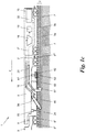
- FIG. 1a to 1c a rail vehicle 1 for renovating a track superstructure 2 is shown.
- the track superstructure 2 includes according to Fig. 3a a ballast bed 3, on (or partially in) which a track 4 consisting of sleepers 5, rails 6 and small iron lies.
- the track superstructure 2 rests on a track substructure 7, the so-called "planum”, made of compacted subsoil (ground).
- the renovation of the track superstructure 2 includes a replacement of the ballast bed 3 and the track 4, ie a replacement of the old ballast 3 ', the old sleepers 5' and the old rails 6 'with new ballast 3 ", new sleepers 5" and new rails 6 ".
- the rail vehicle 1 usually consists of several cars coupled to form a train (even if this is not mandatory) and the in the Figures 1a to 1c Components shown of the rail vehicle 1 are distributed to different cars according to their respective space and weight requirements.
- Fig. 1 shows an exemplary car division of the rail vehicle 1 into a central car 8 with three chassis 8 ', 8 ", 8'", with the car 8 optionally having a joint 9 at the location of the middle chassis 8 " Seen in the direction of travel F, one or more transport trolleys 10, 11 for depositing old sleepers 5 'and for stocking new sleepers 5 "are coupled at the front.
- the wagons 10, 11 are equipped with corresponding movable gantry cranes 12 for manipulating the old and new sleepers 5 ', 5 ", in particular to place the new sleepers 5" from the transport carriage 11 onto a conveyor belt 13 leading to the carriage 8 and the old sleepers 5' from lift off a conveyor belt 14 leading away from the carriage 8 and place it on the transport carriage 10.
- one (or more) wagons 15 for recycling old ballast 3 'from ballast bed 3 to new ballast 3 "and for storing and supplying new ballast 3" are coupled to the central carriage 8.
- the wagon (s) 15 contain one or more high-performance sieves 16, to which the old ballast 3 'is fed from the wagon 8 via conveyor belts 17, 18 and which sift out the upper and lower grains and discharge them into a waste container 19.
- the rail vehicle 1 can have further cars (not shown), such as locomotives, hydraulic units for driving the various devices of the rail vehicle 1, etc.
- the conveyor belts 17, 18, 20, 21 shown are only shown as examples and in part; it goes without saying that these can be divided into several successive conveyor belt sections, in particular at the articulation and coupling points of the carriages 8, 10, 11, 15, as is known in the art.
- the rail vehicle 1 optionally has a small iron releasing device 23 for mechanical releasing, separating, removing or the like. of the small iron, by means of which the old rails 6 'are attached to the old sleepers 5'.
- the small iron 24 can for example be screws, nuts, bolts, clamps, springs, etc., as known to those skilled in the art.
- the small iron release device 23 opens, separates or removes the small iron 24 in a destructive or non-destructive manner.
- the small iron loosening device 23 includes drills, rotary hammers, chisels, cutting torches, cutting discs, water jet cutters, Laser or the like. By means of which the small iron 24 is mechanically released, separated or destroyed when the rail vehicle 1 passes over it.
- the small iron 24 can also be automatically removed by the small iron release device 23 e.g. placed in the middle between the old rails 6 'and / or from an integrated receiving device, e.g. a gripper, a shovel, a magnet or the like, e.g. a magnetic conveyor belt (not shown), are collected and stored in a storage container.
- an integrated receiving device e.g. a gripper, a shovel, a magnet or the like, e.g. a magnetic conveyor belt (not shown)
- the rail vehicle 1 has a threading device 25 for the old rails 6 'in order to spread them outwards.
- the old rails 6 'spread outward by the threading device 25 are, for example, placed in a conventional manner laterally outside the original track 4 and dismantled in sections for removal.
- the threading device 25 is located as the first component in a central work area A of the rail vehicle 1, which is located between the two front chassis 8 ′ and 8 ′′ of the car 8.
- the rail vehicle 1 is optionally supported in the work area A by means of a drive caterpillar 26 on the old sleepers 5 ', which initially remain without rails.
- the drive caterpillar 26 generates propulsion for the rail vehicle 1 by rolling on the old rails 5 '.
- a removal device 27 for the old sleepers 5 ' is arranged downstream of the optional drive caterpillar 26.
- the removal device 27 grabs the old sleepers 5 'for example by means of a gripper 28 on the sleeper heads and places them on the conveyor belt 14, which leads to the carriage 10 with the old sleeper depository.
- ballast bed clearing device 29 removes the entire ballast bed 3 down to the subgrade 7, either only in a central area 30 ( Fig. 3a ) directly below track 4, so that ballast bed flanks 31 remain next to it for the time being, or over the entire width of ballast bed 3, ie including ballast bed flanks 31. It is also possible that ballast bed clearing device 29 clears so wide that it also clears the the flanks 31 adjoining edge paths 32 next to the gravel bed 3 clears or cleans.
- the ballast bed clearing device 29 can also dip slightly and in particular asymmetrically or obliquely into the subgrade 7 in order to remove it horizontally or in a wedge shape, ie with a subgrade surface 7 'inclined transversely to the direction of travel F.
- Such an inclined subgrade surface 7 ' serves to drain the track superstructure 2, so that rainwater which seeps through the ballast bed 3 and hits the compacted subgrade surface 7' is carried away transversely to the direction of travel F.
- the ballast bed clearing device 29 can, for example, be a clearing chain running transversely over the ballast bed 3, which in its rear area is guided obliquely upward over the conveyor belt 17, which conveys the old ballast 3 'to the recycling truck 15.
- Fig. 4 shows an alternative embodiment of the ballast bed clearing device 29 in the form of a pair of counter-rotating screw conveyors 34 which are mounted on one side on a carrier 33 of the rail vehicle 1 and which interact with lateral ploughshares, guide plates or blades 35 in order to move the central area 30 or the area 30 including the Flanks 31 or the area 30 including the flanks 31 and the edge areas 32 to clear.
- the screw conveyors 34 convey directly onto the conveyor belt 17 which has been pulled down to there.
- the conveyor belt 17 can be designed as a plastic conveyor belt.
- the lateral plowshares, guide plates or blades 35 can be mounted pivotably on the carrier 33, as shown at 36, in order to adjust the clearing width of the ballast bed clearing device 29.
- the screw conveyors 34 can also be mounted pivotably on the carrier 33 in order to optimally adapt their conveying effect to the opening angle of the shields 35.
- ballast bed clearing device 29 especially if it moves the ballast bed 3 over the central area 30 ( Fig. 3a ) including the flanks 31 and edge paths 32 clears - optionally a rolling device 38 for rolling a geotextile 39 onto the now exposed surface 7 'of the subgrade 7 downstream.
- the rail vehicle 1 has a ballast bed application device 40.
- An embodiment of the ballast bed application device 40 not according to the invention is shown in FIG Figure 1b shown, an embodiment of the invention in Fig. 2 .
- the ballast bed application device 40 is supplied with new ballast 3 ′′ from the recycling wagon 15, more precisely the output of the high-performance screen 16, optionally supplemented by new ballast 3 ′′ from the silo unit 22, via the conveyor belt 21.
- the ballast bed application device 40 is designed to apply the new ballast 3 ′′ in at least two layers, namely a first, lower ballast layer 3a and a second, overlying ballast layer 3b the first ballast layer 3a, a compacting device 42 for compacting the first ballast layer 3a, and then a second ballast application device 43 for applying the second ballast layer 3b.
- ballast bed application device 40 can also apply the new ballast 3 ′′ in more than two layers 3a, 3b and for this purpose can also have more than two ballast application devices 41, 43, between each of which there is a corresponding compacting device 42.
- the two ballast application devices 41 and 43 are conveyor belts or ballast trousers or chutes which are fed by a common hopper 44 are fed, which is fed from the conveyor belt 21 with new ballast 3 ".
- the ballast bed application device 40 can contain an optional unrolling device 45 for applying or unrolling a geotextile 46 on the upper side of the just compacted first gravel layer 3a.
- the ballast bed application device 40 applies the new ballast 3 ′′ in the two layers 3a and 3b over the same width of the track superstructure 2 that was previously cleared by the ballast bed clearing device 29, ie either over the middle area 30 or the area 30 plus the flanks 31.
- Fig. 2 shows an inventive.
- Embodiment of the two-stage ballast bed application device 40 in the form of a funnel 47 with a first outlet shaft 48, which forms the first ballast application device 41, and a second, downstream outlet shaft 49, which forms the second ballast application device 43.
- the funnel 47 is charged with new ballast 3 ′′ from the conveyor belt 21, the new ballast 3 ′′ being divided into the two outlet shafts 48, 49 by a central separating element 50 in the funnel 47.
- one (or more) screw conveyors 51 with an axis running transversely to the direction of travel F are arranged in the first ballast application device 41.
- the conveyor screw (s) 51 compacts / compacts the new ballast 3 ′′ emerging from the outlet shaft 48 through its conveying effect, so that the ballast layer 3a emerges immediately compressed.
- ballast bed application device 40 can be followed by a further compacting device (not shown) for compacting the upper ballast layer 3b as well.
- the ballast bed application device 40 can be designed to apply one or both of the ballast layers 3a, 3b with a wedge-shaped cross-section — seen transversely to the direction of travel F — as in FIG Figures 3b and 3c shown.
- the surface 7 'of the subgrade 7 is horizontal, while in the example of Figure 3c was removed in a wedge shape for drainage.
- the surface inclination of the ballast wedge of new ballast 3 ′′ resulting from the two layers 3a and 3b can even run in the opposite direction to the surface inclination of the subgrade 7.
- ballast wedge 3 increases the cant on the outside of the arch Rail 6 erected opposite the rail 6 on the inside of the arch. Track superelevations of 120 to 160 mm are possible with such a ballast bed application device 40. Only the first ballast layer 3a or only the second ballast layer 3b can be applied in a wedge shape or both ballast layers 3a, 3b.
- the wedge-shaped shape of the ballast layers 3a, 3b can be achieved by appropriate design of the outlet shafts of the ballast application devices 41, 43, for example by correspondingly wedge-shaped design of the outlet gaps that are located at the outlet of the outlet shaft 48 between the subgrade surface 7 'and the separating element 50 and on Exit of the outlet shaft 49 between the surface of the layer 3a and the shaft wall 47 result.
- the term “wedge-shaped” is also understood to mean a trapezoidal shape, such as that used in, for example Figures 3b and 3c is shown.
- ballast bed application device 40 can contain a transverse conveyor which conveys new ballast 3 ′′ to the wedge base of the ballast wedge in order to counteract the effect of gravity of the rail vehicle 1 inclined transversely to the direction of travel.
- the screw conveyor 51 can also be used if its conveying direction is selected such that it conveys the new ballast 3 ′′ that hits it in the direction of the outside of the arch, so that it is increasingly discharged from the outlet shaft 48 there.
- Such a screw conveyor 51 can be used for this purpose can also be arranged in the outlet shaft 49.
- Such transverse conveyors in the ballast application devices 41, 43 can, however, also be implemented in other ways, for example by conveyor belts, rakes, etc. circulating therein transversely to the direction of travel F.
- a depositing device 52 for depositing the new sleepers 5 ′′ on the new ballast bed 3 is arranged on the rail vehicle 1 after the ballast bed application device 40.
- the new sleeper depositing device 52 is fed from the new sleeper supply of the carriage 11 via the conveyor belt 13 and the gantry crane 12.
- the depositing device 52 contains, for example, a corresponding separating device (not shown) for precisely adjusted depositing of the new sleepers 5 ′′ occurring at the end of the conveyor belt 13.
- the rail vehicle 1 can optionally be equipped with a support ski 53, which slides on the newly deposited new sleepers 5 ′′ to support the rail vehicle 1 or rolls off by means of a caterpillar.
- new sleeper depositing device 52 and the optional support ski 53 there is a threading device 54 for new rails 6 "are provided, which had been prepared on the side of the track body, for example lashed there to form strands.
- the new rails 6" are spread out by the threading device 54 and placed on the new sleepers 5 ".
- an air conditioning device 54 'can optionally be arranged to bring the new rails 6 ′′ to the correct temperature, for example 16-22 ° C., so that they already have the correct preload in the installed position and for later welding
- the air-conditioning device 54 'can contain, for example, an inductive heating device and / or a cooling unit, for example water cooling.
- a subsequent small iron fastening device 55 automatically attaches the threaded new rails 6 ′′ to the new sleepers 5 ′′.
- the small iron fastening device 55 can be, for example, an automatic screwing, bolting, clamping or welding machine.
- the rail vehicle 1 contains a ballast bed flank clearing device 56 on each track side with a downstream ballast bed flank application device 57.
- the ballast bed flank clearing device 56 can For example, it can be a clearing chain which conveys the old ballast 3 ′ from the flanks 31 of the ballast bed 3, possibly together with residual material from the edge paths 32, onto the conveyor belt 18, which leads to the recycling carriage 15 leads.
- the ballast bed flank application device 57 is in turn charged with new ballast 3 ′′ from the recycling carriage 15 by the conveyor belt 20 in order to fill up the flanks 31 of the ballast bed 3.
- each ballast bed flank clearing device 56 here contains one (or two) counter-rotating conveyor screw (s) 58 mounted on one side on a carrier 57 of the rail vehicle 1, which are equipped with lateral plowshares , Guide plates or shields 59, 60 cooperate or cooperate in order to clear the flanks 31 and possibly also the edge regions 32.
- the screw conveyors 58 each convey on a conveyor belt 20, which can be designed as a plastic conveyor belt for the purpose of noise insulation.
- the plowshares, guide plates or blades 59, 60 can be pivotably articulated on the carrier 57 in order to adjust the clearing width of each gravel bed side clearing device 56.
- the middle shields 59 which serve to delimit the central area 30 and the flanks 31 of the ballast bed 3, can be fixed in the manner of cutting edges.
- the rail vehicle 1 has, following the optional components 55, 56 and 57, a tamping unit 61 with tamping picks 62 in order to tamp the new track 4 with the new ballast 3 ′′ in the new ballast bed 3.
- the tamping unit 61 can, as is known in the art , with a Track lifting and straightening unit 63 can be combined in order to correctly adjust track 4 in the new ballast bed 3.
- the tamping tines 62 of the tamping unit 61 preferably penetrate into the lower layer 3a if no geotextile 46 is used. In exceptional cases and when using a geotextile 46, the tamping tines 62 can only reach down into the upper layer 3b of the new track bed 3 and leave the compacted lower layer 3a and the optional geotextile 46 untouched. In the course of the track tamping with the tamping unit 61, further new ballast 3 ′′ can also be filled in, for example in order to also ball the sleeper heads of the new sleepers 5 ′′.
Landscapes
- Engineering & Computer Science (AREA)
- Architecture (AREA)
- Civil Engineering (AREA)
- Structural Engineering (AREA)
- Machines For Laying And Maintaining Railways (AREA)
Claims (19)
- Véhicule sur rails (1) pour la rénovation de la superstructure des voies, avec au moins deux châssis (8', 8", 8'") et, entre eux, une zone de travail (A) dans laquelle le véhicule sur rails (1) présente, le long de la direction de déplacement (F) successivement,
un dispositif de démontage (25) pour les anciens rails (6'),
un dispositif de retrait (27) pour les anciennes traverses (5'),
un dispositif de déblayage du lit de ballast (29),
un dispositif de mise en place du lit de ballast (40),
un dispositif de dépôt (52) pour des nouvelles traverses (5") et
un dispositif de montage (54) pour des nouveaux rails (6"),
où le dispositif de mise en place du lit de ballast (40) est conçu pour mettre en place du nouveau ballast (3") en au moins deux couches et comprend à cette fin successivement:un premier dispositif de mise en place de ballast (41) pour la mise en place d'une première couche de ballast (3a) inférieure,un dispositif de compactage pour le compactage de la première couche de ballast (3a), etun deuxième dispositif de mise en place de ballast (43) pour la mise en place d'une deuxième couche de ballast (3b) se situant au-dessus,caractérisé en ce que le dispositif de mise en place du lit de ballast (40) a la forme d'un entonnoir (47) avec un premier conduit de sortie (48) formant le premier dispositif de mise en place de ballast (41), un consécutif deuxième conduit de sortie (49) formant le deuxième dispositif de mise en place de ballast (43), et un élément de séparation (50) central dans l'entonnoir (47) pour la distribution du nouveau ballast (3") entre les deux conduits de sortie (48, 49),où le dispositif de compactage est formé par une ou plusieurs vis de transport (51) disposée/s dans le premier dispositif de mise en place de ballast (41) avec une axe/des axes s'étendant perpendiculairement par rapport à la direction de déplacement (F) et avec une direction de rotation inversée par rapport à la direction de déplacement (F), de sorte que la première couche de ballast (3a) inférieure est mise en place directement compactée. - Véhicule sur rails selon la revendication 1, caractérisé par une unité de bourrage (61), disposée après le dispositif de montage (54), laquelle est de préférence une unité combinée de levage de rail, d'orientation et de bourrage (61, 63).
- Véhicule sur rails selon la revendication 1 ou 2, caractérisé en ce qu'au moins un des dispositifs de mise en place de ballast (41, 43) est conçu pour mettre en place sa couche de ballast (3a, 3b) avec une section transversale en forme le coin.
- Véhicule sur rails selon la revendication 3, caractérisé en ce qu'au moins un des dispositifs de mise en place de ballast (41, 43) contient un transporteur transversal (51) pour l'aide a la mise en place de ballast plus accru au côté de base du coin.
- Véhicule sur rails selon l'une des revendications 1 à 4, caractérisé en ce que le dispositif de déblayage du lit de ballast (29) plonge dans la plate-forme (7) se situant en-dessous du lit de ballast (3) afin de décaper celle-ci en forme de coin.
- Véhicule sur rails selon l'une des revendications 1 à 5, caractérisé en ce qu'un dispositif de déroulage (45) pour un géotextile (46) est disposé entre le dispositif de compactage (42) et le deuxième dispositif de mise en place de ballast (43) .
- Véhicule sur rails selon l'une des revendications 1 à 6, caractérisé par un dispositif de détachement de petites ferrures (23) disposé avant le dispositif de démontage (25).
- Véhicule sur rails selon l'une des revendications 1 à 7, caractérisé par un dispositif de fixation de petites ferrures (55) disposé après le dispositif de montage (54).
- Véhicule sur rails selon l'une des revendications 1 à 8, caractérisé en ce que, dans la zone du dispositif de montage des nouveaux rails (54), un dispositif de climatisation (54') est prévu pour le préchauffage, et/ou le refroidissement, des nouveaux rails (6").
- Véhicule sur rails selon l'une des revendications 1 à 9, caractérisé en ce que le dispositif de déblayage du lit de ballast (29) est conçu pour déplayer également la structure de flancs (31) du lit de ballast (3) se situant à l'extérieur de la voie, éventuellement conjointement avec des dépôts sur la piste latérale (32) de la voie.
- Véhicule sur rails selon la revendication 10, caractérisé en ce qu'un autre dispositif de déroulage (38) pour le déroulage d'un autre géotextile (39) est disposé entre le dispositif de déblayage du lit de ballast (29) et le dispositif de mise en place du lit de ballast (40).
- Véhicule sur rails selon l'une des revendications 1 à 11, caractérisé en ce que le dispositif de déblayage du lit de ballast (29) est formé par une paire de vis de transport (34), marchant en sens contraires, chacune logée sur un seul côté.
- Véhicule sur rails selon l'une des revendications 1 à 12, caractérisé en ce qu'un dispositif de déblayage de flancs de lit de ballast (56), avec un dispositif de mise en place de flancs de lit de ballast (57) disposé après, est prévu sur chaque côté de la voie.
- Véhicule sur rails selon la revendication 13, caractérisé en ce que chaque dispositif de déblayage de flanc de lit de ballast (56) est formé par une ou deux vis de transport (58) marchant en sens contraires, chacune logée sur un seul côté.
- Véhicule sur rails selon la revendication 12 ou 14, caractérisé en ce que les vis de transport (34, 58) déchargent sur une bande transporteuse en matière plastique (17, 20) disposée après.
- Véhicule sur rails selon la revendication 12, 14 ou 15, caractérisé en ce qu'un soc de charrue, ou une tôle de guidage, ou un panneau de guidage (35, 59, 60), de préférence réglable en pivotant, est disposé latéralement par rapport à chaque vis de transport (34, 58).
- Véhicule sur rails selon l'une des revendications 1 à 16, caractérisé en ce qu'une chenille d'entraînement (26) est prévue entre le dispositif de démontage (25) et le dispositif de retrait (27).
- Véhicule sur rails selon l'une des revendications 1 à 17, caractérisé en ce qu'au moins un ski de soutien (53) est prévu entre le dispositif de dépôt (52) et le dispositif de montage (54).
- Véhicule sur rails selon l'une des revendications 1 à 18, caractérisé en ce que le dispositif de déblayage du lit de ballast (29) recycle ses déblais par des bandes transporteuses (17, 21) et une installation de tamisage (16) vers le dispositif de mise en place du lit de ballast (40).
Applications Claiming Priority (1)
| Application Number | Priority Date | Filing Date | Title |
|---|---|---|---|
| ATA50474/2017A AT520040B1 (de) | 2017-06-06 | 2017-06-06 | Schienenfahrzeug zur Gleisoberbausanierung |
Publications (2)
| Publication Number | Publication Date |
|---|---|
| EP3412827A1 EP3412827A1 (fr) | 2018-12-12 |
| EP3412827B1 true EP3412827B1 (fr) | 2020-08-26 |
Family
ID=62002548
Family Applications (1)
| Application Number | Title | Priority Date | Filing Date |
|---|---|---|---|
| EP18167517.4A Active EP3412827B1 (fr) | 2017-06-06 | 2018-04-16 | Véhicule ferroviaire destiné à l'assainissement de superstructure de voie |
Country Status (4)
| Country | Link |
|---|---|
| EP (1) | EP3412827B1 (fr) |
| AT (1) | AT520040B1 (fr) |
| DK (1) | DK3412827T3 (fr) |
| HU (1) | HUE052550T2 (fr) |
Families Citing this family (2)
| Publication number | Priority date | Publication date | Assignee | Title |
|---|---|---|---|---|
| AT522237B1 (de) * | 2019-03-14 | 2024-05-15 | Plasser & Theurer Export Von Bahnbaumaschinen Gmbh | Verfahren zum Verdichten eines Schotterbettes eines Gleises |
| CN112048950A (zh) * | 2020-09-18 | 2020-12-08 | 俞中毅 | 一种可以实现自动补充道碴的枕底道碴清筛机及使用方法 |
Family Cites Families (10)
| Publication number | Priority date | Publication date | Assignee | Title |
|---|---|---|---|---|
| AT375426B (de) * | 1982-09-20 | 1984-08-10 | Plasser Bahnbaumasch Franz | Foerder- bzw. raeumkettenanordnung fuer eine gleisbaumaschine |
| JPS59107604U (ja) * | 1982-12-28 | 1984-07-20 | 日本国有鉄道 | 線路側部バラストかき出し機 |
| AT384445B (de) * | 1986-02-12 | 1987-11-10 | Plasser Bahnbaumasch Franz | Fahrbare anlage zur erneuerung der schienen und schwellen eines gleises |
| DE69112729T2 (de) * | 1990-07-13 | 1996-05-02 | Scheuchzer Sa | Vorrichtung zur Auswechselung von Eisenbahnschienen. |
| AT3918U3 (de) * | 2000-07-13 | 2001-08-27 | Plasser Bahnbaumasch Franz | Maschine zur erneuerung eines gleises |
| PL2054552T3 (pl) * | 2006-08-25 | 2014-06-30 | Sersa Maschineller Gleisbau Ag | Sposób i zespół urządzeń do renowacji nasypu wykonanego z tłucznia |
| DE202008003589U1 (de) * | 2008-03-14 | 2009-07-30 | Wiebe Holding Gmbh & Co. Kg | Gleiswegsanierungsmaschine mit Tragschichtfräse |
| AT511698B1 (de) * | 2011-12-14 | 2013-02-15 | Plasser Bahnbaumasch Franz | Verfahren zur planumsanierung |
| AT513248B1 (de) * | 2012-12-11 | 2014-03-15 | Plasser Bahnbaumasch Franz | Verfahren und Maschine zur Reinigung von Schotter eines Gleises |
| AT14304U1 (de) * | 2014-05-13 | 2015-08-15 | Plasser & Theurer Export Von Bahnbaumaschinen Gmbh | Verfahren zur Erneuerung einer Schotterbettung eines Gleises |
-
2017
- 2017-06-06 AT ATA50474/2017A patent/AT520040B1/de active
-
2018
- 2018-04-16 EP EP18167517.4A patent/EP3412827B1/fr active Active
- 2018-04-16 HU HUE18167517A patent/HUE052550T2/hu unknown
- 2018-04-16 DK DK18167517.4T patent/DK3412827T3/da active
Non-Patent Citations (1)
| Title |
|---|
| None * |
Also Published As
| Publication number | Publication date |
|---|---|
| DK3412827T3 (da) | 2020-11-30 |
| AT520040A1 (de) | 2018-12-15 |
| HUE052550T2 (hu) | 2021-05-28 |
| EP3412827A1 (fr) | 2018-12-12 |
| AT520040B1 (de) | 2021-01-15 |
Similar Documents
| Publication | Publication Date | Title |
|---|---|---|
| EP0255564B1 (fr) | Machine pour remplacer ou rénover respectivement les rails et les traverses d'une voie existante | |
| EP0629744B1 (fr) | Procédé et installation pour l'assainissement de l'infrastructure du ballast d'une voie | |
| DD207014A5 (de) | Fahrbare anlage und verfahren zur kontinuierlich fortschreitenden sanierung des gleisunterbaues | |
| AT398097B (de) | Anlage zur herstellung einer planumschutzschichte | |
| DD256157A5 (de) | Fahrbare anlage der schotterbeseitigung eines gleises | |
| EP1253247B1 (fr) | Machine pour nettoyer le ballast d' une voie ferrée | |
| DD253268A5 (de) | Gleisstopfmaschine | |
| AT3879U2 (de) | Maschine zur erneuerung eines gleises | |
| DD253266A5 (de) | Fahrbare anlage zum reinigen und anschliessenden verdichten der schotterbettung von gleisen | |
| EP1253246A2 (fr) | Machine pour nettoyer le ballast d' une voie ferrée | |
| EP0408839A1 (fr) | Ensemble de machines déplaçable sur voie pour enlever, nettoyer et remettre en place le ballast d'une voie ferrée | |
| EP0609647B1 (fr) | Machine pour le renouvellement ou nettoyage d'un lit de ballast | |
| DE4441221B4 (de) | Maschinenanlage zur Behandlung der Schotterbettung eines Gleises | |
| AT3917U2 (de) | Maschine zur erneuerung eines gleises | |
| EP1253248B1 (fr) | Méthode et machine pour nettoyer le ballast | |
| EP3412827B1 (fr) | Véhicule ferroviaire destiné à l'assainissement de superstructure de voie | |
| EP1179634B1 (fr) | Machine de renouvellement d'une voie ferrée | |
| DD253267A5 (de) | Fahrbare anlage zur kontinuierlichen erneuerung der schienen und schwellen eines gleises | |
| DE202008003589U1 (de) | Gleiswegsanierungsmaschine mit Tragschichtfräse | |
| DE2557372A1 (de) | Fahrbare gleisbaumaschine, insbesondere weichenreinigungsmaschine | |
| EP2848736B1 (fr) | Train de travaux de chemin de fer pour retirer et installer du ballast et des tronçons assemblés de voie ferrée | |
| DE20107520U1 (de) | Reinigungsmaschine zur Reinigung der Schotterbettung eines Gleises | |
| EP0551835A1 (fr) | Dispositif pour la mise en place du sable ou du ballast entre la plate-forme et les rails d'une voie ferrée, et procédé pour remplacer la superstructure de la voie | |
| DE102006059639A1 (de) | Verfahren und Vorrichtung zum Herstellen oder Erneuern einer geschotterten Schienenfahrbahn | |
| DE4241742A1 (fr) |
Legal Events
| Date | Code | Title | Description |
|---|---|---|---|
| PUAI | Public reference made under article 153(3) epc to a published international application that has entered the european phase |
Free format text: ORIGINAL CODE: 0009012 |
|
| STAA | Information on the status of an ep patent application or granted ep patent |
Free format text: STATUS: THE APPLICATION HAS BEEN PUBLISHED |
|
| AK | Designated contracting states |
Kind code of ref document: A1 Designated state(s): AL AT BE BG CH CY CZ DE DK EE ES FI FR GB GR HR HU IE IS IT LI LT LU LV MC MK MT NL NO PL PT RO RS SE SI SK SM TR |
|
| AX | Request for extension of the european patent |
Extension state: BA ME |
|
| STAA | Information on the status of an ep patent application or granted ep patent |
Free format text: STATUS: REQUEST FOR EXAMINATION WAS MADE |
|
| STAA | Information on the status of an ep patent application or granted ep patent |
Free format text: STATUS: EXAMINATION IS IN PROGRESS |
|
| 17P | Request for examination filed |
Effective date: 20190611 |
|
| RBV | Designated contracting states (corrected) |
Designated state(s): AL AT BE BG CH CY CZ DE DK EE ES FI FR GB GR HR HU IE IS IT LI LT LU LV MC MK MT NL NO PL PT RO RS SE SI SK SM TR |
|
| 17Q | First examination report despatched |
Effective date: 20190712 |
|
| RAP1 | Party data changed (applicant data changed or rights of an application transferred) |
Owner name: SWIETELSKY AG |
|
| GRAP | Despatch of communication of intention to grant a patent |
Free format text: ORIGINAL CODE: EPIDOSNIGR1 |
|
| STAA | Information on the status of an ep patent application or granted ep patent |
Free format text: STATUS: GRANT OF PATENT IS INTENDED |
|
| INTG | Intention to grant announced |
Effective date: 20200316 |
|
| GRAJ | Information related to disapproval of communication of intention to grant by the applicant or resumption of examination proceedings by the epo deleted |
Free format text: ORIGINAL CODE: EPIDOSDIGR1 |
|
| STAA | Information on the status of an ep patent application or granted ep patent |
Free format text: STATUS: EXAMINATION IS IN PROGRESS |
|
| GRAR | Information related to intention to grant a patent recorded |
Free format text: ORIGINAL CODE: EPIDOSNIGR71 |
|
| GRAS | Grant fee paid |
Free format text: ORIGINAL CODE: EPIDOSNIGR3 |
|
| STAA | Information on the status of an ep patent application or granted ep patent |
Free format text: STATUS: GRANT OF PATENT IS INTENDED |
|
| GRAA | (expected) grant |
Free format text: ORIGINAL CODE: 0009210 |
|
| STAA | Information on the status of an ep patent application or granted ep patent |
Free format text: STATUS: THE PATENT HAS BEEN GRANTED |
|
| INTC | Intention to grant announced (deleted) | ||
| INTG | Intention to grant announced |
Effective date: 20200716 |
|
| RIN1 | Information on inventor provided before grant (corrected) |
Inventor name: GAL, PETER Inventor name: SCHAUER, NORBERT |
|
| AK | Designated contracting states |
Kind code of ref document: B1 Designated state(s): AL AT BE BG CH CY CZ DE DK EE ES FI FR GB GR HR HU IE IS IT LI LT LU LV MC MK MT NL NO PL PT RO RS SE SI SK SM TR |
|
| REG | Reference to a national code |
Ref country code: GB Ref legal event code: FG4D Free format text: NOT ENGLISH |
|
| REG | Reference to a national code |
Ref country code: CH Ref legal event code: EP |
|
| REG | Reference to a national code |
Ref country code: DE Ref legal event code: R096 Ref document number: 502018002261 Country of ref document: DE |
|
| REG | Reference to a national code |
Ref country code: AT Ref legal event code: REF Ref document number: 1306475 Country of ref document: AT Kind code of ref document: T Effective date: 20200915 |
|
| REG | Reference to a national code |
Ref country code: IE Ref legal event code: FG4D Free format text: LANGUAGE OF EP DOCUMENT: GERMAN |
|
| REG | Reference to a national code |
Ref country code: NL Ref legal event code: FP |
|
| REG | Reference to a national code |
Ref country code: DK Ref legal event code: T3 Effective date: 20201123 |
|
| REG | Reference to a national code |
Ref country code: SE Ref legal event code: TRGR |
|
| REG | Reference to a national code |
Ref country code: LT Ref legal event code: MG4D |
|
| REG | Reference to a national code |
Ref country code: SK Ref legal event code: T3 Ref document number: E 35589 Country of ref document: SK |
|
| PG25 | Lapsed in a contracting state [announced via postgrant information from national office to epo] |
Ref country code: LT Free format text: LAPSE BECAUSE OF FAILURE TO SUBMIT A TRANSLATION OF THE DESCRIPTION OR TO PAY THE FEE WITHIN THE PRESCRIBED TIME-LIMIT Effective date: 20200826 Ref country code: HR Free format text: LAPSE BECAUSE OF FAILURE TO SUBMIT A TRANSLATION OF THE DESCRIPTION OR TO PAY THE FEE WITHIN THE PRESCRIBED TIME-LIMIT Effective date: 20200826 Ref country code: BG Free format text: LAPSE BECAUSE OF FAILURE TO SUBMIT A TRANSLATION OF THE DESCRIPTION OR TO PAY THE FEE WITHIN THE PRESCRIBED TIME-LIMIT Effective date: 20201126 Ref country code: PT Free format text: LAPSE BECAUSE OF FAILURE TO SUBMIT A TRANSLATION OF THE DESCRIPTION OR TO PAY THE FEE WITHIN THE PRESCRIBED TIME-LIMIT Effective date: 20201228 Ref country code: FI Free format text: LAPSE BECAUSE OF FAILURE TO SUBMIT A TRANSLATION OF THE DESCRIPTION OR TO PAY THE FEE WITHIN THE PRESCRIBED TIME-LIMIT Effective date: 20200826 Ref country code: GR Free format text: LAPSE BECAUSE OF FAILURE TO SUBMIT A TRANSLATION OF THE DESCRIPTION OR TO PAY THE FEE WITHIN THE PRESCRIBED TIME-LIMIT Effective date: 20201127 |
|
| REG | Reference to a national code |
Ref country code: NO Ref legal event code: T2 Effective date: 20200826 |
|
| PG25 | Lapsed in a contracting state [announced via postgrant information from national office to epo] |
Ref country code: RS Free format text: LAPSE BECAUSE OF FAILURE TO SUBMIT A TRANSLATION OF THE DESCRIPTION OR TO PAY THE FEE WITHIN THE PRESCRIBED TIME-LIMIT Effective date: 20200826 Ref country code: LV Free format text: LAPSE BECAUSE OF FAILURE TO SUBMIT A TRANSLATION OF THE DESCRIPTION OR TO PAY THE FEE WITHIN THE PRESCRIBED TIME-LIMIT Effective date: 20200826 Ref country code: IS Free format text: LAPSE BECAUSE OF FAILURE TO SUBMIT A TRANSLATION OF THE DESCRIPTION OR TO PAY THE FEE WITHIN THE PRESCRIBED TIME-LIMIT Effective date: 20201226 |
|
| PG25 | Lapsed in a contracting state [announced via postgrant information from national office to epo] |
Ref country code: RO Free format text: LAPSE BECAUSE OF FAILURE TO SUBMIT A TRANSLATION OF THE DESCRIPTION OR TO PAY THE FEE WITHIN THE PRESCRIBED TIME-LIMIT Effective date: 20200826 Ref country code: EE Free format text: LAPSE BECAUSE OF FAILURE TO SUBMIT A TRANSLATION OF THE DESCRIPTION OR TO PAY THE FEE WITHIN THE PRESCRIBED TIME-LIMIT Effective date: 20200826 Ref country code: SM Free format text: LAPSE BECAUSE OF FAILURE TO SUBMIT A TRANSLATION OF THE DESCRIPTION OR TO PAY THE FEE WITHIN THE PRESCRIBED TIME-LIMIT Effective date: 20200826 |
|
| REG | Reference to a national code |
Ref country code: DE Ref legal event code: R097 Ref document number: 502018002261 Country of ref document: DE |
|
| REG | Reference to a national code |
Ref country code: HU Ref legal event code: AG4A Ref document number: E052550 Country of ref document: HU |
|
| PG25 | Lapsed in a contracting state [announced via postgrant information from national office to epo] |
Ref country code: AL Free format text: LAPSE BECAUSE OF FAILURE TO SUBMIT A TRANSLATION OF THE DESCRIPTION OR TO PAY THE FEE WITHIN THE PRESCRIBED TIME-LIMIT Effective date: 20200826 Ref country code: ES Free format text: LAPSE BECAUSE OF FAILURE TO SUBMIT A TRANSLATION OF THE DESCRIPTION OR TO PAY THE FEE WITHIN THE PRESCRIBED TIME-LIMIT Effective date: 20200826 |
|
| PLBE | No opposition filed within time limit |
Free format text: ORIGINAL CODE: 0009261 |
|
| STAA | Information on the status of an ep patent application or granted ep patent |
Free format text: STATUS: NO OPPOSITION FILED WITHIN TIME LIMIT |
|
| 26N | No opposition filed |
Effective date: 20210527 |
|
| PG25 | Lapsed in a contracting state [announced via postgrant information from national office to epo] |
Ref country code: SI Free format text: LAPSE BECAUSE OF FAILURE TO SUBMIT A TRANSLATION OF THE DESCRIPTION OR TO PAY THE FEE WITHIN THE PRESCRIBED TIME-LIMIT Effective date: 20200826 |
|
| PG25 | Lapsed in a contracting state [announced via postgrant information from national office to epo] |
Ref country code: MC Free format text: LAPSE BECAUSE OF FAILURE TO SUBMIT A TRANSLATION OF THE DESCRIPTION OR TO PAY THE FEE WITHIN THE PRESCRIBED TIME-LIMIT Effective date: 20200826 |
|
| PG25 | Lapsed in a contracting state [announced via postgrant information from national office to epo] |
Ref country code: CH Free format text: LAPSE BECAUSE OF NON-PAYMENT OF DUE FEES Effective date: 20210430 Ref country code: LI Free format text: LAPSE BECAUSE OF NON-PAYMENT OF DUE FEES Effective date: 20210430 |
|
| PG25 | Lapsed in a contracting state [announced via postgrant information from national office to epo] |
Ref country code: IE Free format text: LAPSE BECAUSE OF NON-PAYMENT OF DUE FEES Effective date: 20210416 |
|
| PG25 | Lapsed in a contracting state [announced via postgrant information from national office to epo] |
Ref country code: IS Free format text: LAPSE BECAUSE OF FAILURE TO SUBMIT A TRANSLATION OF THE DESCRIPTION OR TO PAY THE FEE WITHIN THE PRESCRIBED TIME-LIMIT Effective date: 20201226 |
|
| GBPC | Gb: european patent ceased through non-payment of renewal fee |
Effective date: 20220416 |
|
| PG25 | Lapsed in a contracting state [announced via postgrant information from national office to epo] |
Ref country code: GB Free format text: LAPSE BECAUSE OF NON-PAYMENT OF DUE FEES Effective date: 20220416 |
|
| PG25 | Lapsed in a contracting state [announced via postgrant information from national office to epo] |
Ref country code: CY Free format text: LAPSE BECAUSE OF FAILURE TO SUBMIT A TRANSLATION OF THE DESCRIPTION OR TO PAY THE FEE WITHIN THE PRESCRIBED TIME-LIMIT Effective date: 20200826 |
|
| PG25 | Lapsed in a contracting state [announced via postgrant information from national office to epo] |
Ref country code: MK Free format text: LAPSE BECAUSE OF FAILURE TO SUBMIT A TRANSLATION OF THE DESCRIPTION OR TO PAY THE FEE WITHIN THE PRESCRIBED TIME-LIMIT Effective date: 20200826 |
|
| PG25 | Lapsed in a contracting state [announced via postgrant information from national office to epo] |
Ref country code: MT Free format text: LAPSE BECAUSE OF FAILURE TO SUBMIT A TRANSLATION OF THE DESCRIPTION OR TO PAY THE FEE WITHIN THE PRESCRIBED TIME-LIMIT Effective date: 20200826 |
|
| PGFP | Annual fee paid to national office [announced via postgrant information from national office to epo] |
Ref country code: NL Payment date: 20250422 Year of fee payment: 8 |
|
| PGFP | Annual fee paid to national office [announced via postgrant information from national office to epo] |
Ref country code: LU Payment date: 20250417 Year of fee payment: 8 |
|
| PGFP | Annual fee paid to national office [announced via postgrant information from national office to epo] |
Ref country code: DE Payment date: 20250417 Year of fee payment: 8 |
|
| PGFP | Annual fee paid to national office [announced via postgrant information from national office to epo] |
Ref country code: DK Payment date: 20250423 Year of fee payment: 8 |
|
| PGFP | Annual fee paid to national office [announced via postgrant information from national office to epo] |
Ref country code: HU Payment date: 20250411 Year of fee payment: 8 Ref country code: NO Payment date: 20250422 Year of fee payment: 8 |
|
| PGFP | Annual fee paid to national office [announced via postgrant information from national office to epo] |
Ref country code: IT Payment date: 20250430 Year of fee payment: 8 Ref country code: BE Payment date: 20250422 Year of fee payment: 8 |
|
| PGFP | Annual fee paid to national office [announced via postgrant information from national office to epo] |
Ref country code: FR Payment date: 20250422 Year of fee payment: 8 |
|
| PGFP | Annual fee paid to national office [announced via postgrant information from national office to epo] |
Ref country code: AT Payment date: 20250327 Year of fee payment: 8 |
|
| PGFP | Annual fee paid to national office [announced via postgrant information from national office to epo] |
Ref country code: SK Payment date: 20250411 Year of fee payment: 8 |
|
| PGFP | Annual fee paid to national office [announced via postgrant information from national office to epo] |
Ref country code: CZ Payment date: 20250404 Year of fee payment: 8 |
|
| PGFP | Annual fee paid to national office [announced via postgrant information from national office to epo] |
Ref country code: SE Payment date: 20250423 Year of fee payment: 8 |
|
| PG25 | Lapsed in a contracting state [announced via postgrant information from national office to epo] |
Ref country code: TR Free format text: LAPSE BECAUSE OF FAILURE TO SUBMIT A TRANSLATION OF THE DESCRIPTION OR TO PAY THE FEE WITHIN THE PRESCRIBED TIME-LIMIT Effective date: 20200826 |
|
| PGFP | Annual fee paid to national office [announced via postgrant information from national office to epo] |
Ref country code: PL Payment date: 20260316 Year of fee payment: 9 |