EP3412838B1 - Radlader und radladersteuerungsverfahren - Google Patents
Radlader und radladersteuerungsverfahren Download PDFInfo
- Publication number
- EP3412838B1 EP3412838B1 EP17846112.5A EP17846112A EP3412838B1 EP 3412838 B1 EP3412838 B1 EP 3412838B1 EP 17846112 A EP17846112 A EP 17846112A EP 3412838 B1 EP3412838 B1 EP 3412838B1
- Authority
- EP
- European Patent Office
- Prior art keywords
- boom
- wheel loader
- sensor
- controller
- action
- Prior art date
- Legal status (The legal status is an assumption and is not a legal conclusion. Google has not performed a legal analysis and makes no representation as to the accuracy of the status listed.)
- Active
Links
Images


Classifications
-
- E—FIXED CONSTRUCTIONS
- E02—HYDRAULIC ENGINEERING; FOUNDATIONS; SOIL SHIFTING
- E02F—DREDGING; SOIL-SHIFTING
- E02F3/00—Dredgers; Soil-shifting machines
- E02F3/04—Dredgers; Soil-shifting machines mechanically-driven
- E02F3/28—Dredgers; Soil-shifting machines mechanically-driven with digging tools mounted on a dipper- or bucket-arm, i.e. there is either one arm or a pair of arms, e.g. dippers, buckets
- E02F3/36—Component parts
- E02F3/42—Drives for dippers, buckets, dipper-arms or bucket-arms
- E02F3/43—Control of dipper or bucket position; Control of sequence of drive operations
- E02F3/431—Control of dipper or bucket position; Control of sequence of drive operations for bucket-arms, front-end loaders, dumpers or the like
-
- E—FIXED CONSTRUCTIONS
- E02—HYDRAULIC ENGINEERING; FOUNDATIONS; SOIL SHIFTING
- E02F—DREDGING; SOIL-SHIFTING
- E02F3/00—Dredgers; Soil-shifting machines
- E02F3/04—Dredgers; Soil-shifting machines mechanically-driven
- E02F3/28—Dredgers; Soil-shifting machines mechanically-driven with digging tools mounted on a dipper- or bucket-arm, i.e. there is either one arm or a pair of arms, e.g. dippers, buckets
- E02F3/36—Component parts
- E02F3/42—Drives for dippers, buckets, dipper-arms or bucket-arms
- E02F3/422—Drive systems for bucket-arms, front-end loaders, dumpers or the like
-
- B—PERFORMING OPERATIONS; TRANSPORTING
- B60—VEHICLES IN GENERAL
- B60Q—ARRANGEMENT OF SIGNALLING OR LIGHTING DEVICES, THE MOUNTING OR SUPPORTING THEREOF OR CIRCUITS THEREFOR, FOR VEHICLES IN GENERAL
- B60Q5/00—Arrangement or adaptation of acoustic signal devices
- B60Q5/005—Arrangement or adaptation of acoustic signal devices automatically actuated
-
- B—PERFORMING OPERATIONS; TRANSPORTING
- B60—VEHICLES IN GENERAL
- B60Q—ARRANGEMENT OF SIGNALLING OR LIGHTING DEVICES, THE MOUNTING OR SUPPORTING THEREOF OR CIRCUITS THEREFOR, FOR VEHICLES IN GENERAL
- B60Q9/00—Arrangement or adaptation of signal devices not provided for in one of main groups B60Q1/00 - B60Q7/00, e.g. haptic signalling
- B60Q9/008—Arrangement or adaptation of signal devices not provided for in one of main groups B60Q1/00 - B60Q7/00, e.g. haptic signalling for anti-collision purposes
-
- E—FIXED CONSTRUCTIONS
- E02—HYDRAULIC ENGINEERING; FOUNDATIONS; SOIL SHIFTING
- E02F—DREDGING; SOIL-SHIFTING
- E02F3/00—Dredgers; Soil-shifting machines
- E02F3/04—Dredgers; Soil-shifting machines mechanically-driven
- E02F3/28—Dredgers; Soil-shifting machines mechanically-driven with digging tools mounted on a dipper- or bucket-arm, i.e. there is either one arm or a pair of arms, e.g. dippers, buckets
- E02F3/34—Dredgers; Soil-shifting machines mechanically-driven with digging tools mounted on a dipper- or bucket-arm, i.e. there is either one arm or a pair of arms, e.g. dippers, buckets with bucket-arms, i.e. a pair of arms, e.g. manufacturing processes, form, geometry, material of bucket-arms directly pivoted on the frames of tractors or self-propelled machines
-
- E—FIXED CONSTRUCTIONS
- E02—HYDRAULIC ENGINEERING; FOUNDATIONS; SOIL SHIFTING
- E02F—DREDGING; SOIL-SHIFTING
- E02F3/00—Dredgers; Soil-shifting machines
- E02F3/04—Dredgers; Soil-shifting machines mechanically-driven
- E02F3/28—Dredgers; Soil-shifting machines mechanically-driven with digging tools mounted on a dipper- or bucket-arm, i.e. there is either one arm or a pair of arms, e.g. dippers, buckets
- E02F3/36—Component parts
- E02F3/42—Drives for dippers, buckets, dipper-arms or bucket-arms
- E02F3/43—Control of dipper or bucket position; Control of sequence of drive operations
- E02F3/431—Control of dipper or bucket position; Control of sequence of drive operations for bucket-arms, front-end loaders, dumpers or the like
- E02F3/434—Control of dipper or bucket position; Control of sequence of drive operations for bucket-arms, front-end loaders, dumpers or the like providing automatic sequences of movements, e.g. automatic dumping or loading, automatic return-to-dig
-
- E—FIXED CONSTRUCTIONS
- E02—HYDRAULIC ENGINEERING; FOUNDATIONS; SOIL SHIFTING
- E02F—DREDGING; SOIL-SHIFTING
- E02F9/00—Component parts of dredgers or soil-shifting machines, not restricted to one of the kinds covered by groups E02F3/00 - E02F7/00
- E02F9/08—Superstructures; Supports for superstructures
- E02F9/0858—Arrangement of component parts installed on superstructures not otherwise provided for, e.g. electric components, fenders, air-conditioning units
-
- E—FIXED CONSTRUCTIONS
- E02—HYDRAULIC ENGINEERING; FOUNDATIONS; SOIL SHIFTING
- E02F—DREDGING; SOIL-SHIFTING
- E02F9/00—Component parts of dredgers or soil-shifting machines, not restricted to one of the kinds covered by groups E02F3/00 - E02F7/00
- E02F9/20—Drives; Control devices
- E02F9/2004—Control mechanisms, e.g. control levers
-
- E—FIXED CONSTRUCTIONS
- E02—HYDRAULIC ENGINEERING; FOUNDATIONS; SOIL SHIFTING
- E02F—DREDGING; SOIL-SHIFTING
- E02F9/00—Component parts of dredgers or soil-shifting machines, not restricted to one of the kinds covered by groups E02F3/00 - E02F7/00
- E02F9/20—Drives; Control devices
- E02F9/2025—Particular purposes of control systems not otherwise provided for
- E02F9/2033—Limiting the movement of frames or implements, e.g. to avoid collision between implements and the cabin
-
- E—FIXED CONSTRUCTIONS
- E02—HYDRAULIC ENGINEERING; FOUNDATIONS; SOIL SHIFTING
- E02F—DREDGING; SOIL-SHIFTING
- E02F9/00—Component parts of dredgers or soil-shifting machines, not restricted to one of the kinds covered by groups E02F3/00 - E02F7/00
- E02F9/24—Safety devices, e.g. for preventing overload
-
- E—FIXED CONSTRUCTIONS
- E02—HYDRAULIC ENGINEERING; FOUNDATIONS; SOIL SHIFTING
- E02F—DREDGING; SOIL-SHIFTING
- E02F9/00—Component parts of dredgers or soil-shifting machines, not restricted to one of the kinds covered by groups E02F3/00 - E02F7/00
- E02F9/26—Indicating devices
- E02F9/261—Surveying the work-site to be treated
- E02F9/262—Surveying the work-site to be treated with follow-up actions to control the work tool, e.g. controller
-
- E—FIXED CONSTRUCTIONS
- E02—HYDRAULIC ENGINEERING; FOUNDATIONS; SOIL SHIFTING
- E02F—DREDGING; SOIL-SHIFTING
- E02F9/00—Component parts of dredgers or soil-shifting machines, not restricted to one of the kinds covered by groups E02F3/00 - E02F7/00
- E02F9/26—Indicating devices
- E02F9/264—Sensors and their calibration for indicating the position of the work tool
- E02F9/265—Sensors and their calibration for indicating the position of the work tool with follow-up actions (e.g. control signals sent to actuate the work tool)
Definitions
- the present invention relates to a wheel loader and a method for controlling the wheel loader.
- a wheel loader that is an example of self-propelled work vehicles includes a traveling apparatus that causes the vehicle to travel, and a work implement that performs various operations/services including excavation.
- the traveling apparatus and the work implement are each driven by driving force from an engine.
- Japanese Patent Laying-Open No. 2008-303574 discloses a wheel loader including a video camera or a laser distance sensor disposed on a front wheel axle case.
- the video camera is configured to capture an image of a road surface forward of a position of a bucket, through a clearance below the bucket.
- the wheel loader also includes a display apparatus configured to display an image captured by the video camera or a distance measured by the laser distance sensor on a place where an operator on an operator's seat sees the image or the distance The operator thus monitors a status of a road surface below a work implement.
- Japanese Patent Laying-Open No. 10-88625 discloses an automatic excavator (e.g., a wheel loader) including a visual sensor constituted of two cameras.
- the visual sensor measures a distance from the automatic excavator to a target to be excavated or a dump truck, for the sake of automatic excavation.
- An operator of a wheel loader simultaneously actuates an accelerator pedal and a boom lever to load, on a bed of a dump truck, soil scooped by a bucket of a work implement.
- the wheel loader thus simultaneously performs fore traveling and boom-raising.
- Such a loading operation/service is also called "dump approach”.
- an operator needs to operate a wheel loader so as to prevent a leading end of a front wheel from colliding with a lateral side of a dump truck and so as to prevent a work implement (particularly, a lower end of a boom) from colliding with the lateral side of the dump truck (specifically, an upper portion of a vessel).
- a work implement particularly, a lower end of a boom
- the operator needs to implement the loading operation/service while checking on the upper and lower locations at the same time.
- the present disclosure has been made in view of the problem described above.
- the present disclosure provides a wheel loader that assists an operation by an operator in loading an excavated object such as excavated soil onto a loading target (e.g., a dump truck).
- the present disclosure also provides a method for controlling the wheel loader.
- a wheel loader assists an operation by an operator in loading an excavated object onto a loading target.
- a dump truck will be described as an example of a loading target onto which an excavated object is loaded; however, the loading target is not limited thereto, but may be a non-self-propelled loading target such as a soil container.
- Fig. 1 is a side view of a wheel loader 1 according to a first embodiment
- Fig. 2 is a top view of wheel loader 1.
- wheel loader 1 includes a main body 5, a work implement 30, wheels 3a and 3b, and an operator's cab 6. Wheel loader 1 is self-propelled in such a manner that wheels 3a and 3b are rotated. In addition, wheel loader 1 performs desired operations/services using work implement 30.
- Main body 5 includes a front frame 5a and a rear frame 5b. Front frame 5a and rear frame 5b are connected to each other by a center pin 81 so as to be swingable laterally.
- Steering cylinders 82 are provided in a pair so as to extend from front frame 5a to rear frame 5b.
- Each steering cylinder 82 is a hydraulic cylinder to be driven by hydraulic oil from a steering pump (not illustrated).
- Front frame 5a swings relative to rear frame 5b by expansion and contraction of steering cylinders 82. This action changes a traveling direction of wheel loader 1.
- Work implement 30 and a pair of front wheels 3a are mounted to front frame 5a.
- Work implement 30 is disposed forward of main body 5.
- Work implement 30 is driven by hydraulic oil from a hydraulic pump 119 (see Fig. 3 ).
- Work implement 30 includes a boom 31, a pair of lift cylinders 33, a bucket 32, a bell crank 34, a tilt cylinder 35, and a tilt rod 36 connecting a distal end of bell crank 34 to bucket 32.
- Boom 31 is rotatably supported by front frame 5a.
- Boom 31 has a proximal end (proximal end) mounted to front frame 5a by a boom pin 7 such that boom 31 is swingable.
- Each lift cylinder 33 has a first end mounted to front frame 5a.
- Each lift cylinder 33 has a second end mounted to boom 31.
- the second end of each lift cylinder 33 is mounted to a lower end of boom 31.
- Front frame 5a and boom 31 are connected to each other by lift cylinders 33.
- Boom 31 swings upward and downward about boom pin 7 by expansion and contraction of lift cylinders 33 using the hydraulic oil from hydraulic pump 119.
- Fig. 1 illustrates only one of lift cylinders 33.
- Bucket 32 is rotatably supported by a leading end of boom 31. Bucket 32 is swingably directed to a distal end of boom 31 by a bucket pin 39.
- Tilt cylinder 35 has a first end mounted to front frame 5a.
- Tilt cylinder 35 has a second end mounted to bell crank 34.
- Bell crank 34 and bucket 32 are connected to each other by a link apparatus (not illustrated).
- Front frame 5a and bucket 32 are connected to each other by tilt cylinder 35, bell crank 34, and the link apparatus.
- Bucket 32 swings upward and downward about bucket pin 39 by expansion and contraction of tilt cylinder 35 using the hydraulic oil from hydraulic pump 119.
- Operator's cab 6 and a pair of rear wheels 3b are mounted to rear frame 5b.
- Operator's cab 6 is mounted on main body 5.
- Operator's cab 6 includes, for example, a seat in which an operator sits, and devices for operations (to be described later).
- Wheel loader 1 further includes a sensor 40 configured to measure a distance between boom 31 and a dump truck as a loading target. Sensor 40 is disposed on boom 31. Sensor 40 therefore moves together with boom 31.
- sensor 40 is disposed at a predetermined position in boom 31.
- the predetermined position is closer to the proximal end of boom 31 than to the distal end of boom 31.
- Sensor 40 is disposed on the lower end of boom 31.
- Sensor 40 is disposed near boom pin 7.
- the phrase "lower end of boom 31" refers to the lower (ground side) half of boom 31, including a lower face of boom 31.
- sensor 40 measures a distance (hereinafter, also referred to as "distance D") between boom 31 and a vessel of the dump truck. Sensor 40 senses the lower end of boom 31. Sensor 40 may be any device for measuring a distance. Examples of sensor 40 may include various devices such as an ultrasonic sensor, a laser sensor, an infrared sensor, and a camera.
- Fig 3 is a perspective view of wheel loader 1.
- boom 31 is raised based on an operation by the operator, so that bucket 32 is also raised,
- the operator decreases a tilt angle (angle ⁇ in Fig. 14 ) of bucket 32 with an excavated object such as excavated soil loaded on the bucket.
- the excavated object is thus loaded onto the loading target such as the dump truck.
- Figs. 4(A) and 4(B) each illustrate a positional relationship between left boom 31 and sensor 40.
- sensor 40 is disposed on lower end 31a of boom 31.
- Sensor 40 includes a housing, and a lens 41 disposed in the housing at a position near the distal end of boom 31.
- lens 41 is disposed on the right side of left boom 31 (i.e., is disposed on left boom 31 at a position near right boom 31); however, the present disclosure is not limited to this configuration.
- lens 41 may be disposed on the left side of left boom 31.
- the sensor may be disposed on right boom 31.
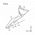
- Fig. 5 schematically illustrates a sensing area of sensor 40. As illustrated in Fig. 5 , sensor 40 is disposed such that an optical axis 48 of sensor 40 extends along boom 31.
- Sensor 40 senses an area covering lower end 31a of boom 31.
- Sensor 40 may sense an area closer to the distal end of boom 31 than to the proximal end of boom 31, in lower end 31a of boom 31.
- sensor 40 senses an area ranging from the position of the second end of each lift cylinder 33 mounted to boom 31 to the distal end of boom 31, in lower end 31a of boom 31.
- sensor 40 may sense a part of each area described above.
- Sensor 40 disposed as described above measures a distance between boom 31 and the dump truck as the loading target.
- Information acquired by sensor 40 is sent to a controller 110 ( Fig. 8 ) of wheel loader 1 and then is subjected to data processing in controller 110 as will be described later.
- Fig. 6 illustrates a typical operation by the operator in dump approach.
- the operator initiates acceleration in a section Q11.
- the operator presses an accelerator pedal (not illustrated)
- the operator actuates a boom control lever 122 ( Fig. 8 ) to raise boom 31 as will be described later.
- wheel loader 1 thus travels toward dump truck 900 while performing boom-raising
- the operator initiates acceleration in section Q11 for the purpose of supplying a satisfactory amount of oil to lift cylinders 33, rather than for the purpose of causing wheel loader 1 to travel.
- Increasing an engine speed ensures an output of hydraulic oil from the hydraulic pump. Accordingly, the operator still presses the accelerator pedal even when he or she presses a brake pedal to decrease a vehicle speed in section Q11.
- a section Q12 subsequent to section Q11 the operator ceases the acceleration and then initiates braking. Specifically, the operator presses the brake pedal (not illustrated) instead of the accelerator pedal. The operator thus brings wheel loader 1 to a stop in front of dump truck 900. Thereafter, the operator actuates a bucket control lever 123 ( Fig. 8 ) to load soil scooped by bucket 32 onto a bed of dump truck 900 as will be described later.
- a broken line La represents a path along which bucket 32 typically moves in the series of operations.
- Figs. 7(A) and 7(B) each illustrate a situation in which the operator does not raise boom 31 to a position where an excavated object is loadable onto vessel 901 of dump truck 900, in the dump approach.
- Fig. 7(A) illustrates the dump approach on the assumption that an output from sensor 40 is not utilized.
- Fig. 7(B) illustrates the dump approach on the assumption that an output from sensor 40 is utilized.
- Fig. 7(A) illustrates a comparative example for clarifying a feature of the damp approach in Fig. 7(B) .
- a broken line Lb represents a path of bucket 32.
- wheel loader 1 (specifically, controller 110) controls boom-raising as illustrated in Fig. 7(B) .
- Wheel loader 1 determines whether distance D to be measured by sensor 40 (i.e., the distance between boom 31 and dump truck 900) takes a value less than or equal to a threshold value. When wheel loader 1 determines that the value of distance D measured is less than or equal to the threshold value, then wheel loader 1 starts to raise boom 31. For example, wheel loader 1 does not raise boom 31 in a section Q21 during which the value of distance D measured is larger than the threshold value. When wheel loader 1 arrives at a section Q22 during which the value of distance D measured is less than or equal to the threshold value, then wheel loader 1 starts to raise boom 31.
- wheel loader 1 includes sensor 40 configured to measure distance D between boom 31 and dump truck 900. Controller 110 of wheel loader 1 causes wheel loader 1 to perform boom-raising on condition that distance D to be measured by sensor 40 when wheel loader 1 travels takes a value less than or equal to the threshold value.
- wheel loader 1 moves boom 31 away from vessel 901 before collision of boom 31 with vessel 901 in the dump approach. Wheel loader 1 accordingly avoids the collision of boom 31 with dump truck 900 even when the operator neglects to confirm the position of boom 31 because he or she pays excessive attention to the position of each front wheel 3a. Wheel loader 1 therefore assists the operation by the operator in the dump approach.
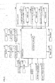
- Fig. 8 is a block diagram of a system configuration of wheel loader 1.
- wheel loader 1 includes boom 31, bucket 32, lift cylinders 33, tilt cylinder 35, sensor 40, controller 110, a boom angle sensor 112, a bucket angle sensor 113, an engine 118, hydraulic pump 119, a control lever 120, control valves 131 and 141, a monitor 151, and a speaker 152.
- Control lever 120 includes a fore/aft traveling switch control lever 121, boom control lever 122, bucket control lever 123, and vibrators 124, 125, and 126.
- Controller 110 includes a determination unit 1101.
- Controller 110 controls the overall actions of wheel loader 1. Controller 110 controls, for example, a rotation speed of engine 118, based on the actuation of the accelerator pedal. In addition, the controller receives a signal based on the actuation of control lever 120 by the operator, and then causes wheel loader 1 to perform an action in accordance with the actuation.
- Hydraulic pump 119 is driven by an output from engine 118. Hydraulic pump 119 supplies the hydraulic oil to lift cylinders 33 via control valve 131 such that boom 31 is driven. Boom 31 is raised or lowered by actuation of boom control lever 122 in operator's cab 6. Hydraulic pump 119 also supplies the hydraulic oil to tilt cylinder 35 via control valve 141 such that bucket 32 is driven. Bucket 32 is acted by actuation of bucket control lever 123 in operator's cab 6.
- Controller 110 successively receives results of sensing from sensor 40.
- determination unit 1101 of controller 110 determines whether distance D to be measured by sensor 40 takes a value less than or equal to threshold value Th.
- controller 110 starts to raise boom 31.
- Controller 110 receives a signal according to a boom angle from boom angle sensor 112. Controller 110 also receives a signal according to a tilt angle from bucket angle sensor 113. A description will be given of how to utilize signals (results of sensing) output from boom angle sensor 112 and bucket angle sensor 113, later.
- Controller 110 causes monitor 151 to display various images. Controller 110 causes speaker 152 to output a predetermined sound. A description will be given of how to utilize monitor 151 and speaker 152, later.
- Vibrator 124 is configured to vibrate fore/aft traveling switch control lever 121.
- Vibrator 125 is configured to vibrate boom control lever 122.
- Vibrator 126 is configured to vibrate bucket control lever 123. A description will be given of how to utilize vibrators 124 to 126, later.
- Fig. 9 is a flowchart of a processing flow in wheel loader 1.
- controller 110 determines whether wheel loader 1 is traveling forward.
- controller 110 determines whether distance D measured by sensor 40 takes a value less than or equal to threshold value Th.
- controller 110 determines that wheel loader 1 is not traveling forward (NO in step S2), the processing goes back to step S2.
- controller 110 determines that the value of distance D is less than or equal to threshold value Th (YES in step S4), then, in step S6, controller 110 starts to raise boom 31.
- controller 110 determines that the value of distance D is larger than threshold value Th (NO in step S4), the processing goes back to step S2.
- controller 110 determines whether distance D measured by sensor 40 takes a value less than or equal to threshold value Th.
- step S14 controller 110 stops boom 31 being raised.
- step S16 controller 110 determines whether wheel loader 1 is traveling forward.
- controller 110 determines that wheel loader 1 is traveling forward (YES in step S16)
- the processing goes back to step S4.
- controller 110 determines that wheel loader 1 is not traveling forward (NO in step S16)
- controller 110 determines whether an angle (a boom angle) of boom 31 is maximum. Specifically, controller 110 determines whether each of lift cylinders 33 has extended to its stroke end.
- controller 110 determines that the boom angle is maximum (YES in step S10), then, in step S12, controller 110 brings wheel loader 1 to a stop. Typically, controller 110 initiates braking even when the operator does not press the braking pedal. When controller 110 determines that the boom angle is not maximum (NO in step S10), the processing goes to step S8.
- controller 110 causes wheel loader 1 to raise boom 31 on condition that distance D takes a value less than or equal to threshold value Th.
- Wheel loader 1 may be configured to allow the operator to forcibly cease the control by controller 110. Examples of such an operation by the operator may include an operation to press down a predetermined button (not illustrated), an operation to actuate boom control lever 122 to lower boom 31, and an operation to shift fore/aft traveling switch control lever 121 from a fore traveling position to an aft traveling position. In wheel loader 1, the operator performs the operation to shift fore/aft traveling switch control lever 121 from the fore traveling position to the aft traveling position even when wheel loader 1 is traveling forward (i.e., is not stopping).
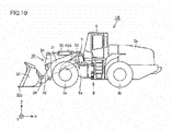
- Fig. 10 is a side view of wheel loader 1A according to the second embodiment.
- Fig. 11 is a top view of wheel loader 1A.
- Fig. 12 is a perspective view of wheel loader 1A.
- wheel loader 1A has a hardware configuration similar to the hardware configuration of wheel loader 1A, except for a sensor 40A provided instead of sensor 40.
- Sensor 40A is disposed on an upper face of a front frame 5a. Sensor 40A is disposed at a predetermined position that is closer to a position where a boom 31 is supported than to a front end 51 (see Fig. 13 ) of front frame 5a. Specifically, sensor 40A is disposed closer to a boom pin 7 than to the front end of front frame 5a.
- Sensor 40A is disposed between a position where left boom 31 is supported and a position where a tilt cylinder 35 is supported, as seen in top view in a Y direction illustrated in Fig 11 .
- Sensor 40A may be disposed between a position where right boom 31 is supported and the position where tilt cylinder 35 is supported, as seen in top view.
- Sensor 40A measures a distance D between boom 31 and dump truck 900 in dump approach, as in a manner similar to that of sensor 40. Specifically, sensor 40A measures distance D between boom 31 and vessel 901 of dump truck 900, as in a manner similar to that of sensor 40. Sensor 40A senses a lower end of boom 31 with boom 31 raised, as in a manner similar to that of sensor 40. Sensor 40A may be any device for measuring distance D. Examples of sensor 40A may include various devices such as an ultrasonic sensor, a laser sensor, an infrared sensor, and a camera.
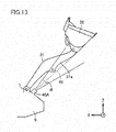
- Fig. 13 schematically illustrates a sensing area of sensor 40A.
- sensor 40A is disposed such that an optical axis 49 of sensor 40A approximately extends along boom 31 with boom 31 raised at an angle greater than or equal to a predetermined angle.
- the sensing area of sensor 40A is set in advance with a boom angle in the dump approach taken into consideration.
- Sensor 40A senses an area covering a lower end 31a of boom 31.
- Sensor 40A may sense an area closer to a distal end of boom 31 than to a proximal end of boom 31, in lower end 31a of boom 31.
- sensor 40A senses an area ranging from a position of a second end of each lift cylinder 33 mounted to boom 31 to the distal end of boom 31, in lower end 31a of boom 31.
- sensor 40A may sense a part of each area described above.
- Sensor 40A disposed as described above measures distance D between boom 31 and the dump truck as the loading target.
- Information acquired by sensor 40A is sent to a controller 110 of wheel loader 1A and then is subjected to data processing in controller 110.
- Controller 110 of wheel loader 1A operates like controller 110 of wheel loader 1. Specifically, controller 110 causes wheel loader 1 to perform a predetermined action for collision avoidance, that is, an action to raise boom 31 on condition that distance D to be measured by sensor 40A when wheel loader 1A travels takes a value less than or equal to a threshold value Th.
- a predetermined action for collision avoidance that is, an action to raise boom 31 on condition that distance D to be measured by sensor 40A when wheel loader 1A travels takes a value less than or equal to a threshold value Th.
- wheel loader 1A moves boom 31 away from vessel 901 before collision of boom 31 with vessel 901 in the dump approach.
- Wheel loader 1A therefore avoids the collision of boom 31 with dump truck 900 even when the operator neglects to confirm the position of boom 31 because he or she operates wheel loader 1A while directing his or her line of sight to front wheels 3a.
- controller 110 causes wheel loader 1 to perform the predetermined action, that is, the action to raise boom 31 on condition that distance D to be measured by sensor 40A when wheel loader 1A travels takes a value less than or equal to threshold value Th.
- the predetermined action is not limited to the action to raise boom 31.
- Controller 110 may cause speaker 152 to output a predetermined audible notification (audible alarm), in place of the control for raising boom 31.
- controller 110 may cause monitor 151 to display a predetermined warning.
- Controller 110 may send a command to each of vibrators 124 to 126 such that vibrators 124 to 126 start to vibrate.
- the vibrations of vibrators 124, 125, and 126 vibrate corresponding control levers 121, 122, and 123. This configuration also makes the operator aware of an abnormal state.
- Wheel loader 1, 1A may be configured to perform the action to raise boom 31, the output of the predetermined audible alarm from speaker 152, the display of the predetermined warning on monitor 151, and the vibrations of vibrators 124 to 126 in appropriate combination.
- Fig. 14 illustrates a tilt angle ⁇ of bucket 32. It should be noted that Fig. 14 illustrates wheel loader 1. As illustrated in Fig. 14 , since an excavated object such as soil is loaded on bucket 32 in the dump approach, the operator needs to set tilt angle ⁇ to be larger than a predetermined angle (hereinafter, also referred to as "angle ⁇ 1").
- wheel loader 1, 1A is not configured to always perform the predetermined action on condition that distance D takes a value less than or equal to threshold value Th, but may be configured to perform the predetermined action on condition that the tilt angle of bucket 32 is greater than or equal to predetermined angle ⁇ 1.
- wheel loader 1, 1A performs the predetermined action on condition that distance D takes a value less than or equal to threshold value Th.
- wheel loader 1, 1A does not perform the predetermined action on condition that the value of distance D is less than or equal to threshold value Th.
- wheel loader 1, 1A approaching dump truck 900 does not perform the predetermined action on condition that no excavated object is loaded on bucket 32.
- Fig. 15 illustrates how to level off an excavated object. It should be noted that Fig. 15 illustrates wheel loader 1. As illustrated in Fig. 15 , when the operator operates wheel loader 1 to load an excavated object onto vessel 901 of dump truck 900, the excavated object can be heaped on vessel 901 beyond the height of vessel 901. In such a case, the operator sets the tilt angle of bucket 32 to be less than or equal to a predetermined angle (hereinafter, referred to as "angle ⁇ 2") that is smaller than angle ⁇ 1. The operator then operates bucket 32 to drop the excavated object heaped beyond the upper side of vessel 901.
- angle ⁇ 2 a predetermined angle
- tilt angle ⁇ of bucket 32 is set at zero (i.e., a state in which a cutting edge 32a is horizontal to main body 5), and then the soil heaped beyond the upper side of vessel 901 is dropped onto the ground opposite from wheel loader 1, 1A across dump truck 900.
- controller 110 causes wheel loader 1 to stop the predetermined action, that is, boom-raising on condition that tilt angle ⁇ is less than or equal to angle ⁇ 2 that is smaller than angle ⁇ 1. This configuration allows the operator to level off the excavated object.
- controller 110 may be configured to cause wheel loader 1, 1A to stop the predetermined action after a transition of wheel loader 1, 1A from a fore traveling state to an aft traveling state. This configuration avoids execution of unnecessary control.
- a wheel loader for loading an excavated object onto a loading target includes: a front frame; a bucket; a boom having a distal end connected to the bucket, and a proximal end rotatably supported by the front frame; a sensor configured to measure a distance between the boom and the loading target, and a controller configured to control an action of the wheel loader.
- the controller causes the wheel loader to perform a predetermined action for collision avoidance on condition that a distance to be measured by the sensor when the wheel loader travels takes a value less than or equal to a threshold value
- the wheel loader traveling forward performs the predetermined action for collision avoidance before collision of the boom with the loading target.
- the wheel loader therefore avoids the collision of the boom with the loading target even when an operator neglects to confirm a position of the boom.
- the wheel loader thus assists an operation by the operator in loading the excavated object onto the loading target.
- the senor is disposed at one of a first position in the boom, the first position being closer to the proximal end of the boom than to the distal end of the boom, and a second position in the front frame, the second position being closer to a position where the boom is supported than to a front end of the front frame.
- the first position corresponds to a lower end of the boom.
- This configuration allows the sensor of the wheel loader to sense the lower end of the boom.
- the senor is disposed at the first position and is configured to sense an area covering a lower end of the boom, the area being closer to the distal end of the boom than to the proximal end of the boom.
- This configuration allows the wheel loader to measure the distance between the boom and the loading target.
- the wheel loader further includes a lift cylinder having one end mounted to a lower end of the boom, the lift cylinder being configured to drive the boom.
- the sensor is disposed at the first position and is configured to sense an area ranging from a position of the lift cylinder mounted to the boom to the distal end of the boom, in the lower end of the boom.
- This configuration allows the wheel loader to measure the distance between the boom and the loading target.
- the predetermined action corresponds to an action to raise the boom.
- This configuration allows the wheel loader traveling forward to move the boom away from the loading target before collision of the boom with the loading target. This configuration therefore allows the wheel loader to avoid the collision of the boom with the loading target even when the operator neglects to confirm the position of the boom.
- the predetermined action corresponds to an action to output a predetermined audible notification.
- This configuration allows the operator to perform an operation to avoid collision of the boom with the loading target in such a manner that the operator listens to the audible notification before the collision of the boom with the loading target.
- the wheel loader further includes a control lever configured to operate the wheel loader.
- the predetermined action corresponds to an action to vibrate the control lever
- This configuration allows the operator to perform the operation to avoid collision of the boom with the loading target in such a manner that the operator feels the vibration of the control lever before the collision of the boom with the loading target.
- the controller brings the wheel loader to a stop on condition that the boom is raised at a maximum angle by the predetermined action.
- This configuration prevents collision of the boom with the loading target in a situation in which the boom collides with the loading target even when the boom is retreated as much as possible.
- the controller causes the wheel loader to perform the predetermined action on condition that a tilt angle of the bucket takes a value greater than or equal to a first value.
- This configuration prevents the wheel loader approaching the loading target from performing the predetermined action for collision avoidance on condition that no excavated object is loaded on the bucket.
- the predetermined action corresponds to an action to raise the boom.
- the controller causes the wheel loader to stop the action to raise the boom on condition that the tilt angle takes a value less than or equal to a second value that is smaller than the first value.
- the controller causes the wheel loader to stop the predetermined action on condition that the controller receives a predetermined input based on an operation by the operator.
- the operator forcibly stops the control for raising the boom on condition that the distance between the boom and the loading target takes a value less than or equal to the threshold value.
- the predetermined action corresponds to an action to raise the boom.
- the operation by the operator corresponds to an operation to lower the boom.
- the wheel loader further includes a fore/aft traveling switch lever configured to switch between fore traveling of the wheel loader and aft traveling of the wheel loader.
- the operation by the operator corresponds to an operation to shift the fore/aft traveling switch lever from a fore traveling position to an aft traveling position.
- the fore/aft traveling switch lever switching operation allows a forcible stop of the control for raising the boom on condition that the distance between the boom and the loading target takes a value less than or equal to the threshold value.
- the controller causes the wheel loader to stop the predetermined action after a transition of the wheel loader from a fore traveling state to an aft traveling state.
- the controller causes the wheel loader in the aft traveling state to stop the action to raise the boom on condition that the distance between the boom and the loading target takes a value less than or equal to the threshold value.
- a method for controlling a wheel loader configured to load an excavated object onto a loading target includes the steps of: measuring a distance between a boom of the wheel loader and the loading target; determining that the distance measured takes a value less than or equal to a threshold value when the wheel loader travels, and causing the wheel loader to perform a predetermined action for collision avoidance on condition that the value of the distance measured is less than or equal to the threshold value.
- the wheel loader traveling forward performs the predetermined action for collision avoidance before collision of the boom with the loading target.
- the wheel loader therefore avoids the collision of the boom with the loading target even when the operator neglects to confirm the position of the boom.
- the wheel loader thus assists an operation by the operator in loading the excavated object onto the loading target.
Landscapes
- Engineering & Computer Science (AREA)
- Mining & Mineral Resources (AREA)
- Civil Engineering (AREA)
- General Engineering & Computer Science (AREA)
- Structural Engineering (AREA)
- Mechanical Engineering (AREA)
- Physics & Mathematics (AREA)
- Acoustics & Sound (AREA)
- Human Computer Interaction (AREA)
- Operation Control Of Excavators (AREA)
- Component Parts Of Construction Machinery (AREA)
Claims (15)
- Ein Radlader (1) zum Laden eines ausgehobenen Objekts zu einem Ladeziel,
der Radlader (1) weist auf:einen Vorderrahmen (5a);eine Schaufel (32);einen Ausleger (31) mit einem distalen Ende, das mit der Schaufel (32) verbunden ist, und einem nahen Ende, das drehbar durch den Vorderrahmen (5a) unterstützt ist,einen Sensor (40), der konfiguriert ist, um eine Distanz zwischen dem Ausleger (31) und dem Ladeziel zu messen, undeinen Controller (110), der konfiguriert ist, eine Aktion des Radladers (1) zu steuern,der Controller (110) bewirkt, dass der Radlader (1) eine vorbestimmte Aktion zum Vermeiden einer Kollision durchführt, unter einer Bedingung, dass eine Distanz die vom Sensor (40) gemessen wird, wenn der Radlader (1) fährt, einen Wert annimmt der kleiner oder gleich einem Schwellwert ist,dadurch gekennzeichnet, dassder Sensor (40) entweder an einer ersten Position in dem Ausleger (31) vorgesehen ist, wobei die erste Position näher an dem nahen Ende des Auslegers (31) vorgesehen ist als das distale Ende des Auslegers (31), oder an einer zweiten Position in dem Vorderrahmen (5a), wobei die zweite Position näher an einer Position ist an der der Ausleger (31) unterstützt ist als ein vorderes Ende des Vorderrahmens (5a). - Der Radlader (1) gemäß Anspruch 1, wobei
die erste Position einem unteren Ende des Auslegers (31) entspricht. - Der Radlader (1) gemäß Anspruch 1 oder 2, wobei
der Sensor (40) an der ersten Position vorgesehen ist und konfiguriert ist, um ein Gebiet zu erfassen, das ein unteres Ende des Auslegers (31) abdeckt, das Gebiet näher zu dem distalen Ende des Auslegers (31) ist als das nahe Ende des Auslegers (31). - Der Radlader (1) gemäß Anspruch 1 oder 2, weiter aufweisend:einen Liftzylinder (33) der mit einem Ende an einem unteren Ende des Auslegers (31) montiert ist, wobei der Liftzylinder (33) konfiguriert ist, um den Ausleger (31) anzutreiben,wobeider Sensor (40) an der ersten Position vorgesehen ist und konfiguriert ist, um ein Gebiet zwischen einer Position des Liftzylinders (33), der am Ausleger (31) montiert ist und dem distalen Ende des Auslegers (31) in dem unteren Ende des Auslegers (31) zu erfassen.
- Der Radlader (1) gemäß einem der Ansprüche 1 bis 4, wobei
die vorbestimmte Aktion einer Aktion entspricht, bei der der Ausleger (31) angehoben wird. - Der Radlader (1) gemäß einem der Ansprüche 1 bis 4, wobei
die vorbestimmte Aktion einer Aktion entspricht, bei der eine vorbestimmte hörbare Notiz ausgegeben wird. - Der Radlader (1) gemäß einem der Ansprüche 1 bis 4, weiter aufweisend:einen Steuerhebel (120), mit dem der Radlader (1) betätigt werden kann,wobeidie vorbestimmte Aktion einer Aktion entspricht, bei der der Kontrollhebel (120) vibriert.
- Der Radlader (1) gemäß Anspruch 5, wobei
der Controller (110) den Radlader (1) zu einem gestoppten Zustand bringt, bei dem der Ausleger (31) mit einem Maximalwinkel durch die vorbestimmten Aktion gehoben ist. - Der Radlader (1) gemäß einem der Ansprüche 1 bis 8, wobei
der Controller (110) bewirkt, dass der Radlader (1) die vorbestimmte Aktion unter der Bedingung ausführt, dass ein Neigungswinkel der Schaufel (32) einen Wert annimmt, der größer oder gleich einem ersten Wert ist. - Der Radlader (1) gemäß Anspruch 9, wobei
die vorbestimmte Aktion eine Aktion zum Anheben des Auslegers (31) entspricht, und
der Controller (110) bewirkt, dass der Radlader (1) die Aktion zum Anheben des Auslegers (31) stoppt, unter der Bedingung, dass der Neigungswinkel einen Wert annimmt kleiner oder gleich einem zweiten Wert, der kleiner als der erste Wert ist. - Der Radlader (1) gemäß einem der Ansprüche 1 bis 10, wobei
der Controller (110) bewirkt, dass der Radlader (1) die vorbestimmte Aktion stoppt, unter der Bedingung, dass der Controller (110) einen vorbestimmten Input erhält, basierend auf einer Betätigung des Bedieners. - Der Radlader (1) gemäß Anspruch 11, wobei
die vorbestimmte Aktion einer Aktion entspricht, bei der der Ausleger (31) angehoben wird und
die Operation des Bedieners einer Operation entspricht, bei der der Ausleger (31) gesenkt wird. - Der Radlader (1) gemäß Anspruch 11, weiter aufweisend:einen Vorwärts/Rückwärtsfahrhebel (121), der konfiguriert ist zwischen einer Vorwärtsfahrt des Radladers (1) und einer Rückwärtsfahrt des Radladers (1) zu schalten,wobeidie Bedienung des Operators einer Bedienung entspricht, bei dem der Vorwärts/ Rückwärtsfahrhebel (121) von einer Vorwärtsfahrposition zu einer Rückwärtsfahrposition geschalten wird.
- Der Radlader (1) gemäß einem der Ansprüche 1 bis 12, wobei
der Controller (110) bewirkt, dass der Radlader (1) nach einer Änderung des Radladers (1) vom Vorwärtsfahrzustand zum Rückwärtsfahrzustand die vorbestimmte Aktion stoppt. - Eine Methode zum Steuern eines Radladers (1), der konfiguriert ist, ein ausgehobenes Objekt auf ein Ladeziel zu laden,
die Methode weist die Schritte auf:Vorsehen eines Sensors (40) entweder an einer ersten Position eines Auslegers (31), wobei die erste Position näher an einem nahen Ende des Auslegers (31) als ein entferntes Ende des Auslegers (31) ist, oder an einer zweiten Position in einem Vorderrahmen (5a), wobei die zweite Position näher an einer Position ist an der der Ausleger (31) unterstützt ist als ein vorderes Ende des Vorderrahmens (5a),Messen einer Distanz zwischen dem Ausleger (31) des Radladers (1) und dem Ladeziel, Bestimmen, dass die gemessene Substanz einen Wert annimmt, der gleich oder weniger einem Schwellwert ist, wenn der Radlader (1) fährt, undBewirken, dass der Radlader (1) eine vorbestimmte Aktion zum Vermeiden einer Kollision unter der Bedingung durchführt, dass der Wert der gemessenen Distanz kleiner oder gleich dem Schwellwert ist.
Applications Claiming Priority (2)
| Application Number | Priority Date | Filing Date | Title |
|---|---|---|---|
| JP2016169498 | 2016-08-31 | ||
| PCT/JP2017/029271 WO2018043104A1 (ja) | 2016-08-31 | 2017-08-14 | ホイールローダおよびホイールローダの制御方法 |
Publications (3)
| Publication Number | Publication Date |
|---|---|
| EP3412838A1 EP3412838A1 (de) | 2018-12-12 |
| EP3412838A4 EP3412838A4 (de) | 2019-08-28 |
| EP3412838B1 true EP3412838B1 (de) | 2020-11-04 |
Family
ID=61300572
Family Applications (1)
| Application Number | Title | Priority Date | Filing Date |
|---|---|---|---|
| EP17846112.5A Active EP3412838B1 (de) | 2016-08-31 | 2017-08-14 | Radlader und radladersteuerungsverfahren |
Country Status (5)
| Country | Link |
|---|---|
| US (3) | US10815640B2 (de) |
| EP (1) | EP3412838B1 (de) |
| JP (1) | JP6914943B2 (de) |
| CN (1) | CN108779628B (de) |
| WO (1) | WO2018043104A1 (de) |
Families Citing this family (28)
| Publication number | Priority date | Publication date | Assignee | Title |
|---|---|---|---|---|
| US10570582B2 (en) * | 2016-11-23 | 2020-02-25 | Caterpillar Inc. | System and method for operating a material-handling machine |
| DE102017215379A1 (de) * | 2017-09-01 | 2019-03-07 | Robert Bosch Gmbh | Verfahren zur Ermittlung einer Kollisionsgefahr |
| WO2019116068A1 (en) * | 2017-12-14 | 2019-06-20 | Volvo Construction Equipment Ab | Method for alerting a person near a vehicle when said vehicle performs a movement and vehicle |
| JP7127313B2 (ja) * | 2018-03-19 | 2022-08-30 | コベルコ建機株式会社 | 建設機械 |
| JP6995687B2 (ja) * | 2018-04-27 | 2022-01-17 | 株式会社小松製作所 | 積込機械の制御装置及び積込機械の制御方法 |
| JP7121532B2 (ja) * | 2018-04-27 | 2022-08-18 | 株式会社小松製作所 | 積込機械の制御装置及び積込機械の制御方法 |
| US10883256B2 (en) * | 2018-05-25 | 2021-01-05 | Deere & Company | Object responsive control system for a work machine |
| US11280063B2 (en) * | 2018-06-19 | 2022-03-22 | Komatsu Ltd. | Work vehicle control system and work vehicle control method |
| JP2020165108A (ja) * | 2019-03-28 | 2020-10-08 | 日立建機株式会社 | 作業車両 |
| JP2020193503A (ja) * | 2019-05-29 | 2020-12-03 | ナブテスコ株式会社 | 作業機械の操縦支援システム、作業機械の操縦支援方法、操縦支援システムの保守支援方法、建設機械 |
| WO2021054436A1 (ja) | 2019-09-18 | 2021-03-25 | 住友重機械工業株式会社 | ショベル |
| JP7282644B2 (ja) * | 2019-09-26 | 2023-05-29 | 日立建機株式会社 | 制御システム |
| JP7306191B2 (ja) * | 2019-09-26 | 2023-07-11 | コベルコ建機株式会社 | 輸送車位置判定装置 |
| JP7283332B2 (ja) | 2019-09-26 | 2023-05-30 | コベルコ建機株式会社 | 容器計測システム |
| US11401684B2 (en) | 2020-03-31 | 2022-08-02 | Caterpillar Inc. | Perception-based alignment system and method for a loading machine |
| AU2020468174A1 (en) * | 2020-09-15 | 2023-03-02 | Sandvik Mining And Construction Oy | Mining machine with a support structure for measurement sensors |
| JP7523305B2 (ja) | 2020-09-30 | 2024-07-26 | 株式会社小松製作所 | 作業機械 |
| US11946230B2 (en) * | 2020-10-28 | 2024-04-02 | Deere & Company | Container load assist system and method for a work vehicle |
| CN116601362A (zh) * | 2020-12-23 | 2023-08-15 | 沃尔沃建筑设备公司 | 挖掘机和用于控制挖掘机的方法和装置 |
| US11987961B2 (en) | 2021-03-29 | 2024-05-21 | Joy Global Surface Mining Inc | Virtual field-based track protection for a mining machine |
| US11939748B2 (en) | 2021-03-29 | 2024-03-26 | Joy Global Surface Mining Inc | Virtual track model for a mining machine |
| US11879231B2 (en) | 2021-04-19 | 2024-01-23 | Deere & Company | System and method of selective automation of loading operation stages for self-propelled work vehicles |
| US12410589B2 (en) | 2021-08-26 | 2025-09-09 | Caterpillar Inc. | Methods and systems for implementing a lock-out command on lever machines |
| JP7569351B2 (ja) * | 2022-03-31 | 2024-10-17 | 日立建機株式会社 | 作業機械 |
| JPWO2024075670A1 (de) | 2022-10-03 | 2024-04-11 | ||
| DE102022213836A1 (de) * | 2022-12-19 | 2024-06-20 | Zf Cv Systems Global Gmbh | Mobile Arbeitsmaschine und Verfahren zur Steuerung einer Sicherheitsfunktion der mobilen Arbeitsmaschine |
| USD1086224S1 (en) * | 2023-05-26 | 2025-07-29 | Volvo Construction Equipment Ab | Wheel loader |
| EP4589078A1 (de) * | 2024-01-22 | 2025-07-23 | Sandvik Mining and Construction Oy | Mobile bergbaumaschine, verfahren zum automatischen deponieren einer last und steuerungssystem |
Family Cites Families (60)
| Publication number | Priority date | Publication date | Assignee | Title |
|---|---|---|---|---|
| JPH0535183Y2 (de) * | 1986-04-08 | 1993-09-07 | ||
| EP0369008B1 (de) * | 1988-05-24 | 1994-01-05 | Kabushiki Kaisha Komatsu Seisakusho | Automatisches getriebe für radhebevorrichtung |
| JP3154358B2 (ja) * | 1992-12-24 | 2001-04-09 | 株式会社小松製作所 | 自走式作業車両の制御装置 |
| JP3537099B2 (ja) * | 1993-07-16 | 2004-06-14 | 株式会社小松製作所 | 産業車両のバケット角制御装置 |
| US5528498A (en) * | 1994-06-20 | 1996-06-18 | Caterpillar Inc. | Laser referenced swing sensor |
| JP3441886B2 (ja) * | 1996-06-18 | 2003-09-02 | 日立建機株式会社 | 油圧建設機械の自動軌跡制御装置 |
| JP2867332B2 (ja) * | 1996-09-03 | 1999-03-08 | 株式会社レンタルのニッケン | 深掘り掘削機の運動規制機構 |
| JPH1088625A (ja) | 1996-09-13 | 1998-04-07 | Komatsu Ltd | 自動掘削機、自動掘削方法および自動積み込み方法 |
| US6108949A (en) * | 1997-12-19 | 2000-08-29 | Carnegie Mellon University | Method and apparatus for determining an excavation strategy |
| US6363632B1 (en) * | 1998-10-09 | 2002-04-02 | Carnegie Mellon University | System for autonomous excavation and truck loading |
| JP4082646B2 (ja) * | 1999-11-19 | 2008-04-30 | 株式会社小松製作所 | 排土板の前方監視装置付き車両 |
| AU2002344089B2 (en) | 2001-10-18 | 2006-06-22 | Hitachi Construction Machinery Co., Ltd. | Hydraulic shovel work amount detection apparatus, work amount detection method, work amount detection result display apparatus |
| JP2003184131A (ja) * | 2001-12-19 | 2003-07-03 | Hitachi Constr Mach Co Ltd | 建設機械の操作装置 |
| US6711838B2 (en) * | 2002-07-29 | 2004-03-30 | Caterpillar Inc | Method and apparatus for determining machine location |
| EP1539523B1 (de) | 2002-09-20 | 2006-05-03 | DaimlerChrysler AG | Verfahren und vorrichtung zur auslösung eines selbsttätigen notbremsvorgangs eines fahrzeugs |
| FI115678B (fi) * | 2003-03-25 | 2005-06-15 | Sandvik Tamrock Oy | Järjestely kaivosajoneuvon törmäyksenestoon |
| JP2006195877A (ja) | 2005-01-17 | 2006-07-27 | Hitachi Constr Mach Co Ltd | 作業機械 |
| JP2007023486A (ja) * | 2005-07-12 | 2007-02-01 | Shin Caterpillar Mitsubishi Ltd | 作業機械における接触回避制御装置 |
| JP2008133657A (ja) | 2006-11-28 | 2008-06-12 | Hitachi Constr Mach Co Ltd | 掘削・積込機械及び自動掘削方法 |
| JP2008144378A (ja) | 2006-12-06 | 2008-06-26 | Shin Caterpillar Mitsubishi Ltd | 遠隔操縦作業機の制御装置 |
| JP2008303574A (ja) | 2007-06-06 | 2008-12-18 | Hitachi Constr Mach Co Ltd | 作業機械 |
| US8386134B2 (en) * | 2007-09-28 | 2013-02-26 | Caterpillar Inc. | Machine to-machine communication system for payload control |
| JP5591104B2 (ja) * | 2008-03-21 | 2014-09-17 | 株式会社小松製作所 | 作業車両、作業車両の制御装置、及び作業車両の作動油量制御方法 |
| CN100582685C (zh) | 2008-03-27 | 2010-01-20 | 山西新元自动化仪表有限公司 | 装载机电子秤 |
| JP4948493B2 (ja) * | 2008-08-28 | 2012-06-06 | 日立建機株式会社 | 建設機械 |
| US9177486B2 (en) | 2009-09-29 | 2015-11-03 | Advanced Training System Llc | Shifter force detection |
| JP5503955B2 (ja) * | 2009-12-14 | 2014-05-28 | 日立建機株式会社 | 作業車両の変速制御装置 |
| WO2012157379A1 (ja) | 2011-05-13 | 2012-11-22 | 日立建機株式会社 | 作業機械の周囲監視装置 |
| US9545048B2 (en) * | 2011-08-15 | 2017-01-17 | Deere & Company | System for automated unloading of an agricultural material |
| EP2758605B1 (de) * | 2011-09-23 | 2016-12-14 | Volvo Construction Equipment AB | Verfahren zur auswahl einer angriffsposition für eine landwirtschaftliche maschine mit einer schaufel |
| KR20130055302A (ko) | 2011-11-18 | 2013-05-28 | 현대중공업 주식회사 | 전자유압식 라이드 컨트롤 시스템 및 방법 |
| US9206587B2 (en) * | 2012-03-16 | 2015-12-08 | Harnischfeger Technologies, Inc. | Automated control of dipper swing for a shovel |
| US8768583B2 (en) * | 2012-03-29 | 2014-07-01 | Harnischfeger Technologies, Inc. | Collision detection and mitigation systems and methods for a shovel |
| JP5529241B2 (ja) * | 2012-11-20 | 2014-06-25 | 株式会社小松製作所 | 作業機械および作業機械の作業量計測方法 |
| KR20150041935A (ko) | 2013-10-10 | 2015-04-20 | 현대중공업 주식회사 | 틸팅 제어장치를 갖춘 포크 부착형 휠 로더 |
| US9593469B2 (en) * | 2013-12-20 | 2017-03-14 | Cnh Industrial America Llc | System and method for controlling a work vehicle based on a monitored tip condition of the vehicle |
| CN105934686B (zh) * | 2014-01-30 | 2019-07-16 | 西门子工业公司 | 用于确定n+1维环境模型的方法和设备及采矿装置 |
| JP6342705B2 (ja) * | 2014-05-12 | 2018-06-13 | 古河ユニック株式会社 | 作業機用ブーム衝突回避装置 |
| JP5717923B1 (ja) * | 2014-05-30 | 2015-05-13 | 株式会社小松製作所 | 作業車両の制御方法、作業車両の制御装置及び作業車両 |
| US9809948B2 (en) * | 2014-05-30 | 2017-11-07 | Komatsu Ltd. | Work vehicle control method, work vehicle control device, and work vehicle |
| US20170121930A1 (en) * | 2014-06-02 | 2017-05-04 | Komatsu Ltd. | Construction machine control system, construction machine, and method of controlling construction machine |
| JP5944006B1 (ja) | 2014-07-30 | 2016-07-05 | 株式会社小松製作所 | 運搬車両、ダンプトラック、及び運搬車両の制御方法 |
| CN105611981B (zh) | 2014-07-30 | 2018-04-03 | 株式会社小松制作所 | 搬运车辆及搬运车辆的控制方法 |
| JP2016065422A (ja) * | 2014-09-26 | 2016-04-28 | 株式会社日立製作所 | 外界認識装置および外界認識装置を用いた掘削機械 |
| US10800406B2 (en) | 2014-12-26 | 2020-10-13 | Komatsu Ltd. | Mining machine, management system of mining machine, and management method of mining machine |
| CN204475392U (zh) * | 2014-12-30 | 2015-07-15 | 阿特拉斯工程机械有限公司 | 挖掘机驾驶室防碰装置 |
| JP6419585B2 (ja) * | 2015-01-13 | 2018-11-07 | 株式会社小松製作所 | 掘削機械、掘削機械の制御方法及び掘削システム |
| US9805618B2 (en) * | 2015-02-06 | 2017-10-31 | Caterpillar Inc. | Real time evaluation and coaching system |
| US9441348B1 (en) * | 2015-03-31 | 2016-09-13 | Caterpillar Inc. | Hydraulic system with operator skill level compensation |
| CN104890661B (zh) | 2015-06-30 | 2018-11-16 | 三一重机有限公司 | 一种精确测量制动距离的液压测试系统及工程机械 |
| US9938688B2 (en) | 2015-07-02 | 2018-04-10 | Caterpillar Inc. | Excavation system providing impact detection |
| US9850639B2 (en) | 2015-07-02 | 2017-12-26 | Caterpillar Inc. | Excavation system having velocity based work tool shake |
| US9587369B2 (en) * | 2015-07-02 | 2017-03-07 | Caterpillar Inc. | Excavation system having adaptive dig control |
| US9732502B2 (en) | 2015-07-02 | 2017-08-15 | Caterpillar Inc. | Excavation system providing impact detection |
| CN205296249U (zh) | 2015-10-13 | 2016-06-08 | 山东欧泰隆重工有限公司 | 一种新型四合一铲斗装载机 |
| US10094093B2 (en) * | 2015-11-16 | 2018-10-09 | Caterpillar Inc. | Machine onboard activity and behavior classification |
| JP6986832B2 (ja) * | 2016-08-26 | 2021-12-22 | 株式会社小松製作所 | ホイールローダおよびホイールローダの制御方法 |
| US10794046B2 (en) * | 2016-09-16 | 2020-10-06 | Hitachi Construction Machinery Co., Ltd. | Work machine |
| DE102017209695A1 (de) | 2017-06-08 | 2018-12-13 | Robert Bosch Gmbh | Verfahren zum Steuern einer Arbeitsbühne, Steuergerät und Neigungswinkelmesssystem für eine Arbeitsbühne |
| JP7038516B2 (ja) * | 2017-09-29 | 2022-03-18 | 日立建機株式会社 | ホイールローダ |
-
2017
- 2017-08-14 WO PCT/JP2017/029271 patent/WO2018043104A1/ja not_active Ceased
- 2017-08-14 CN CN201780016921.9A patent/CN108779628B/zh active Active
- 2017-08-14 JP JP2018537098A patent/JP6914943B2/ja active Active
- 2017-08-14 US US16/082,284 patent/US10815640B2/en active Active
- 2017-08-14 EP EP17846112.5A patent/EP3412838B1/de active Active
-
2020
- 2020-09-17 US US17/023,673 patent/US11674285B2/en active Active
-
2023
- 2023-05-01 US US18/141,646 patent/US12241221B2/en active Active
Non-Patent Citations (1)
| Title |
|---|
| None * |
Also Published As
| Publication number | Publication date |
|---|---|
| EP3412838A1 (de) | 2018-12-12 |
| JPWO2018043104A1 (ja) | 2019-06-24 |
| US10815640B2 (en) | 2020-10-27 |
| JP6914943B2 (ja) | 2021-08-04 |
| US20210032837A1 (en) | 2021-02-04 |
| WO2018043104A1 (ja) | 2018-03-08 |
| US12241221B2 (en) | 2025-03-04 |
| US20190093311A1 (en) | 2019-03-28 |
| EP3412838A4 (de) | 2019-08-28 |
| US11674285B2 (en) | 2023-06-13 |
| CN108779628B (zh) | 2021-06-08 |
| CN108779628A (zh) | 2018-11-09 |
| US20230257960A1 (en) | 2023-08-17 |
Similar Documents
| Publication | Publication Date | Title |
|---|---|---|
| US12241221B2 (en) | Wheel loader and method for controlling wheel loader | |
| EP3412837B1 (de) | Radlader und radladersteuerungsverfahren | |
| JP7450083B2 (ja) | 周辺監視システム及び周辺監視方法 | |
| EP3110146B1 (de) | Hinderniserkennungsvorrichtung für eine arbeitsmaschine | |
| CN110494613B (zh) | 工作机械 | |
| US10442442B2 (en) | Work vehicle periphery monitoring system and work vehicle periphery monitoring method | |
| JP2019163669A (ja) | 作業車両 | |
| CN114729524A (zh) | 路面状况监视系统、作业车辆、路面状况监视方法以及程序 | |
| JP4030051B2 (ja) | 作業車両の作業機制御方法及び作業機制御装置 | |
| JP2018114923A (ja) | 作業車 | |
| US20160236606A1 (en) | Method for controlling hoisting of an articulated machine | |
| EP4283052B1 (de) | Steuerungssystem für arbeitsmaschine und steuerungsverfahren für arbeitsmaschine | |
| JP7685965B2 (ja) | 作業機械の安全システム、作業機械、及びサーバ | |
| US12460379B2 (en) | Collision avoidance system and method for avoiding collision of work machine with obstacles | |
| JP2020165834A (ja) | 作業車両 | |
| JP7572887B2 (ja) | 作業機械の異常判定システム及び作業機械の異常判定方法 | |
| US12612767B2 (en) | Work machine abnormality determination system and work machine abnormality determination method | |
| JP2026000069A (ja) | 遠隔操作支援システム、作業車両の遠隔操作装置、および遠隔操作支援方法 | |
| JP2018114926A (ja) | 作業車 |
Legal Events
| Date | Code | Title | Description |
|---|---|---|---|
| STAA | Information on the status of an ep patent application or granted ep patent |
Free format text: STATUS: THE INTERNATIONAL PUBLICATION HAS BEEN MADE |
|
| PUAI | Public reference made under article 153(3) epc to a published international application that has entered the european phase |
Free format text: ORIGINAL CODE: 0009012 |
|
| STAA | Information on the status of an ep patent application or granted ep patent |
Free format text: STATUS: REQUEST FOR EXAMINATION WAS MADE |
|
| 17P | Request for examination filed |
Effective date: 20180904 |
|
| AK | Designated contracting states |
Kind code of ref document: A1 Designated state(s): AL AT BE BG CH CY CZ DE DK EE ES FI FR GB GR HR HU IE IS IT LI LT LU LV MC MK MT NL NO PL PT RO RS SE SI SK SM TR |
|
| AX | Request for extension of the european patent |
Extension state: BA ME |
|
| A4 | Supplementary search report drawn up and despatched |
Effective date: 20190729 |
|
| RIC1 | Information provided on ipc code assigned before grant |
Ipc: E02F 9/24 20060101AFI20190723BHEP Ipc: E02F 3/43 20060101ALI20190723BHEP Ipc: E02F 9/20 20060101ALI20190723BHEP Ipc: E02F 3/42 20060101ALI20190723BHEP Ipc: E02F 9/08 20060101ALI20190723BHEP Ipc: E02F 9/26 20060101ALI20190723BHEP |
|
| DAV | Request for validation of the european patent (deleted) | ||
| DAX | Request for extension of the european patent (deleted) | ||
| RIC1 | Information provided on ipc code assigned before grant |
Ipc: E02F 3/43 20060101ALI20200713BHEP Ipc: E02F 9/26 20060101ALI20200713BHEP Ipc: E02F 9/20 20060101ALI20200713BHEP Ipc: E02F 3/42 20060101ALI20200713BHEP Ipc: E02F 9/08 20060101ALI20200713BHEP Ipc: E02F 9/24 20060101AFI20200713BHEP |
|
| GRAP | Despatch of communication of intention to grant a patent |
Free format text: ORIGINAL CODE: EPIDOSNIGR1 |
|
| STAA | Information on the status of an ep patent application or granted ep patent |
Free format text: STATUS: GRANT OF PATENT IS INTENDED |
|
| INTG | Intention to grant announced |
Effective date: 20200826 |
|
| GRAS | Grant fee paid |
Free format text: ORIGINAL CODE: EPIDOSNIGR3 |
|
| GRAA | (expected) grant |
Free format text: ORIGINAL CODE: 0009210 |
|
| STAA | Information on the status of an ep patent application or granted ep patent |
Free format text: STATUS: THE PATENT HAS BEEN GRANTED |
|
| AK | Designated contracting states |
Kind code of ref document: B1 Designated state(s): AL AT BE BG CH CY CZ DE DK EE ES FI FR GB GR HR HU IE IS IT LI LT LU LV MC MK MT NL NO PL PT RO RS SE SI SK SM TR |
|
| REG | Reference to a national code |
Ref country code: GB Ref legal event code: FG4D |
|
| REG | Reference to a national code |
Ref country code: CH Ref legal event code: EP |
|
| REG | Reference to a national code |
Ref country code: AT Ref legal event code: REF Ref document number: 1330989 Country of ref document: AT Kind code of ref document: T Effective date: 20201115 |
|
| REG | Reference to a national code |
Ref country code: IE Ref legal event code: FG4D |
|
| REG | Reference to a national code |
Ref country code: DE Ref legal event code: R096 Ref document number: 602017027117 Country of ref document: DE |
|
| REG | Reference to a national code |
Ref country code: SE Ref legal event code: TRGR |
|
| REG | Reference to a national code |
Ref country code: NL Ref legal event code: MP Effective date: 20201104 |
|
| REG | Reference to a national code |
Ref country code: AT Ref legal event code: MK05 Ref document number: 1330989 Country of ref document: AT Kind code of ref document: T Effective date: 20201104 |
|
| PG25 | Lapsed in a contracting state [announced via postgrant information from national office to epo] |
Ref country code: GR Free format text: LAPSE BECAUSE OF FAILURE TO SUBMIT A TRANSLATION OF THE DESCRIPTION OR TO PAY THE FEE WITHIN THE PRESCRIBED TIME-LIMIT Effective date: 20210205 Ref country code: NO Free format text: LAPSE BECAUSE OF FAILURE TO SUBMIT A TRANSLATION OF THE DESCRIPTION OR TO PAY THE FEE WITHIN THE PRESCRIBED TIME-LIMIT Effective date: 20210204 Ref country code: RS Free format text: LAPSE BECAUSE OF FAILURE TO SUBMIT A TRANSLATION OF THE DESCRIPTION OR TO PAY THE FEE WITHIN THE PRESCRIBED TIME-LIMIT Effective date: 20201104 Ref country code: PT Free format text: LAPSE BECAUSE OF FAILURE TO SUBMIT A TRANSLATION OF THE DESCRIPTION OR TO PAY THE FEE WITHIN THE PRESCRIBED TIME-LIMIT Effective date: 20210304 Ref country code: FI Free format text: LAPSE BECAUSE OF FAILURE TO SUBMIT A TRANSLATION OF THE DESCRIPTION OR TO PAY THE FEE WITHIN THE PRESCRIBED TIME-LIMIT Effective date: 20201104 |
|
| PG25 | Lapsed in a contracting state [announced via postgrant information from national office to epo] |
Ref country code: BG Free format text: LAPSE BECAUSE OF FAILURE TO SUBMIT A TRANSLATION OF THE DESCRIPTION OR TO PAY THE FEE WITHIN THE PRESCRIBED TIME-LIMIT Effective date: 20210204 Ref country code: PL Free format text: LAPSE BECAUSE OF FAILURE TO SUBMIT A TRANSLATION OF THE DESCRIPTION OR TO PAY THE FEE WITHIN THE PRESCRIBED TIME-LIMIT Effective date: 20201104 Ref country code: LV Free format text: LAPSE BECAUSE OF FAILURE TO SUBMIT A TRANSLATION OF THE DESCRIPTION OR TO PAY THE FEE WITHIN THE PRESCRIBED TIME-LIMIT Effective date: 20201104 Ref country code: IS Free format text: LAPSE BECAUSE OF FAILURE TO SUBMIT A TRANSLATION OF THE DESCRIPTION OR TO PAY THE FEE WITHIN THE PRESCRIBED TIME-LIMIT Effective date: 20210304 Ref country code: AT Free format text: LAPSE BECAUSE OF FAILURE TO SUBMIT A TRANSLATION OF THE DESCRIPTION OR TO PAY THE FEE WITHIN THE PRESCRIBED TIME-LIMIT Effective date: 20201104 Ref country code: ES Free format text: LAPSE BECAUSE OF FAILURE TO SUBMIT A TRANSLATION OF THE DESCRIPTION OR TO PAY THE FEE WITHIN THE PRESCRIBED TIME-LIMIT Effective date: 20201104 |
|
| REG | Reference to a national code |
Ref country code: LT Ref legal event code: MG9D |
|
| PG25 | Lapsed in a contracting state [announced via postgrant information from national office to epo] |
Ref country code: HR Free format text: LAPSE BECAUSE OF FAILURE TO SUBMIT A TRANSLATION OF THE DESCRIPTION OR TO PAY THE FEE WITHIN THE PRESCRIBED TIME-LIMIT Effective date: 20201104 |
|
| PG25 | Lapsed in a contracting state [announced via postgrant information from national office to epo] |
Ref country code: EE Free format text: LAPSE BECAUSE OF FAILURE TO SUBMIT A TRANSLATION OF THE DESCRIPTION OR TO PAY THE FEE WITHIN THE PRESCRIBED TIME-LIMIT Effective date: 20201104 Ref country code: CZ Free format text: LAPSE BECAUSE OF FAILURE TO SUBMIT A TRANSLATION OF THE DESCRIPTION OR TO PAY THE FEE WITHIN THE PRESCRIBED TIME-LIMIT Effective date: 20201104 Ref country code: LT Free format text: LAPSE BECAUSE OF FAILURE TO SUBMIT A TRANSLATION OF THE DESCRIPTION OR TO PAY THE FEE WITHIN THE PRESCRIBED TIME-LIMIT Effective date: 20201104 Ref country code: SM Free format text: LAPSE BECAUSE OF FAILURE TO SUBMIT A TRANSLATION OF THE DESCRIPTION OR TO PAY THE FEE WITHIN THE PRESCRIBED TIME-LIMIT Effective date: 20201104 Ref country code: SK Free format text: LAPSE BECAUSE OF FAILURE TO SUBMIT A TRANSLATION OF THE DESCRIPTION OR TO PAY THE FEE WITHIN THE PRESCRIBED TIME-LIMIT Effective date: 20201104 Ref country code: RO Free format text: LAPSE BECAUSE OF FAILURE TO SUBMIT A TRANSLATION OF THE DESCRIPTION OR TO PAY THE FEE WITHIN THE PRESCRIBED TIME-LIMIT Effective date: 20201104 |
|
| REG | Reference to a national code |
Ref country code: DE Ref legal event code: R097 Ref document number: 602017027117 Country of ref document: DE |
|
| PG25 | Lapsed in a contracting state [announced via postgrant information from national office to epo] |
Ref country code: DK Free format text: LAPSE BECAUSE OF FAILURE TO SUBMIT A TRANSLATION OF THE DESCRIPTION OR TO PAY THE FEE WITHIN THE PRESCRIBED TIME-LIMIT Effective date: 20201104 |
|
| PLBE | No opposition filed within time limit |
Free format text: ORIGINAL CODE: 0009261 |
|
| STAA | Information on the status of an ep patent application or granted ep patent |
Free format text: STATUS: NO OPPOSITION FILED WITHIN TIME LIMIT |
|
| 26N | No opposition filed |
Effective date: 20210805 |
|
| PG25 | Lapsed in a contracting state [announced via postgrant information from national office to epo] |
Ref country code: NL Free format text: LAPSE BECAUSE OF FAILURE TO SUBMIT A TRANSLATION OF THE DESCRIPTION OR TO PAY THE FEE WITHIN THE PRESCRIBED TIME-LIMIT Effective date: 20201104 Ref country code: AL Free format text: LAPSE BECAUSE OF FAILURE TO SUBMIT A TRANSLATION OF THE DESCRIPTION OR TO PAY THE FEE WITHIN THE PRESCRIBED TIME-LIMIT Effective date: 20201104 Ref country code: IT Free format text: LAPSE BECAUSE OF FAILURE TO SUBMIT A TRANSLATION OF THE DESCRIPTION OR TO PAY THE FEE WITHIN THE PRESCRIBED TIME-LIMIT Effective date: 20201104 |
|
| PG25 | Lapsed in a contracting state [announced via postgrant information from national office to epo] |
Ref country code: SI Free format text: LAPSE BECAUSE OF FAILURE TO SUBMIT A TRANSLATION OF THE DESCRIPTION OR TO PAY THE FEE WITHIN THE PRESCRIBED TIME-LIMIT Effective date: 20201104 |
|
| REG | Reference to a national code |
Ref country code: CH Ref legal event code: PL |
|
| PG25 | Lapsed in a contracting state [announced via postgrant information from national office to epo] |
Ref country code: MC Free format text: LAPSE BECAUSE OF FAILURE TO SUBMIT A TRANSLATION OF THE DESCRIPTION OR TO PAY THE FEE WITHIN THE PRESCRIBED TIME-LIMIT Effective date: 20201104 |
|
| REG | Reference to a national code |
Ref country code: BE Ref legal event code: MM Effective date: 20210831 |
|
| GBPC | Gb: european patent ceased through non-payment of renewal fee |
Effective date: 20210814 |
|
| PG25 | Lapsed in a contracting state [announced via postgrant information from national office to epo] |
Ref country code: LI Free format text: LAPSE BECAUSE OF NON-PAYMENT OF DUE FEES Effective date: 20210831 Ref country code: CH Free format text: LAPSE BECAUSE OF NON-PAYMENT OF DUE FEES Effective date: 20210831 |
|
| PG25 | Lapsed in a contracting state [announced via postgrant information from national office to epo] |
Ref country code: IS Free format text: LAPSE BECAUSE OF FAILURE TO SUBMIT A TRANSLATION OF THE DESCRIPTION OR TO PAY THE FEE WITHIN THE PRESCRIBED TIME-LIMIT Effective date: 20210304 Ref country code: LU Free format text: LAPSE BECAUSE OF NON-PAYMENT OF DUE FEES Effective date: 20210814 |
|
| PG25 | Lapsed in a contracting state [announced via postgrant information from national office to epo] |
Ref country code: IE Free format text: LAPSE BECAUSE OF NON-PAYMENT OF DUE FEES Effective date: 20210814 Ref country code: GB Free format text: LAPSE BECAUSE OF NON-PAYMENT OF DUE FEES Effective date: 20210814 Ref country code: FR Free format text: LAPSE BECAUSE OF NON-PAYMENT OF DUE FEES Effective date: 20210831 Ref country code: BE Free format text: LAPSE BECAUSE OF NON-PAYMENT OF DUE FEES Effective date: 20210831 |
|
| PG25 | Lapsed in a contracting state [announced via postgrant information from national office to epo] |
Ref country code: CY Free format text: LAPSE BECAUSE OF FAILURE TO SUBMIT A TRANSLATION OF THE DESCRIPTION OR TO PAY THE FEE WITHIN THE PRESCRIBED TIME-LIMIT Effective date: 20201104 |
|
| PG25 | Lapsed in a contracting state [announced via postgrant information from national office to epo] |
Ref country code: HU Free format text: LAPSE BECAUSE OF FAILURE TO SUBMIT A TRANSLATION OF THE DESCRIPTION OR TO PAY THE FEE WITHIN THE PRESCRIBED TIME-LIMIT; INVALID AB INITIO Effective date: 20170814 |
|
| PG25 | Lapsed in a contracting state [announced via postgrant information from national office to epo] |
Ref country code: MK Free format text: LAPSE BECAUSE OF FAILURE TO SUBMIT A TRANSLATION OF THE DESCRIPTION OR TO PAY THE FEE WITHIN THE PRESCRIBED TIME-LIMIT Effective date: 20201104 |
|
| PG25 | Lapsed in a contracting state [announced via postgrant information from national office to epo] |
Ref country code: MT Free format text: LAPSE BECAUSE OF FAILURE TO SUBMIT A TRANSLATION OF THE DESCRIPTION OR TO PAY THE FEE WITHIN THE PRESCRIBED TIME-LIMIT Effective date: 20201104 |
|
| PGFP | Annual fee paid to national office [announced via postgrant information from national office to epo] |
Ref country code: DE Payment date: 20250702 Year of fee payment: 9 |
|
| PGFP | Annual fee paid to national office [announced via postgrant information from national office to epo] |
Ref country code: SE Payment date: 20250702 Year of fee payment: 9 |
|
| PG25 | Lapsed in a contracting state [announced via postgrant information from national office to epo] |
Ref country code: TR Free format text: LAPSE BECAUSE OF FAILURE TO SUBMIT A TRANSLATION OF THE DESCRIPTION OR TO PAY THE FEE WITHIN THE PRESCRIBED TIME-LIMIT Effective date: 20201104 |