EP3412859B1 - Rollladenkasten - Google Patents
Rollladenkasten Download PDFInfo
- Publication number
- EP3412859B1 EP3412859B1 EP18000034.1A EP18000034A EP3412859B1 EP 3412859 B1 EP3412859 B1 EP 3412859B1 EP 18000034 A EP18000034 A EP 18000034A EP 3412859 B1 EP3412859 B1 EP 3412859B1
- Authority
- EP
- European Patent Office
- Prior art keywords
- profile
- roller blind
- wall
- connection
- plaster
- Prior art date
- Legal status (The legal status is an assumption and is not a legal conclusion. Google has not performed a legal analysis and makes no representation as to the accuracy of the status listed.)
- Active
Links
Images

Classifications
-
- E—FIXED CONSTRUCTIONS
- E06—DOORS, WINDOWS, SHUTTERS, OR ROLLER BLINDS IN GENERAL; LADDERS
- E06B—FIXED OR MOVABLE CLOSURES FOR OPENINGS IN BUILDINGS, VEHICLES, FENCES OR LIKE ENCLOSURES IN GENERAL, e.g. DOORS, WINDOWS, BLINDS, GATES
- E06B9/00—Screening or protective devices for wall or similar openings, with or without operating or securing mechanisms; Closures of similar construction
- E06B9/02—Shutters, movable grilles, or other safety closing devices, e.g. against burglary
- E06B9/08—Roll-type closures
- E06B9/11—Roller shutters
- E06B9/17—Parts or details of roller shutters, e.g. suspension devices, shutter boxes, wicket doors, ventilation openings
- E06B9/17007—Shutter boxes; Details or component parts thereof
- E06B9/1703—Fixing of the box; External plastering of the box
-
- E—FIXED CONSTRUCTIONS
- E06—DOORS, WINDOWS, SHUTTERS, OR ROLLER BLINDS IN GENERAL; LADDERS
- E06B—FIXED OR MOVABLE CLOSURES FOR OPENINGS IN BUILDINGS, VEHICLES, FENCES OR LIKE ENCLOSURES IN GENERAL, e.g. DOORS, WINDOWS, BLINDS, GATES
- E06B9/00—Screening or protective devices for wall or similar openings, with or without operating or securing mechanisms; Closures of similar construction
- E06B9/02—Shutters, movable grilles, or other safety closing devices, e.g. against burglary
- E06B9/08—Roll-type closures
- E06B9/11—Roller shutters
- E06B9/17—Parts or details of roller shutters, e.g. suspension devices, shutter boxes, wicket doors, ventilation openings
- E06B2009/17069—Insulation
Definitions
- the invention relates to a roller shutter box with a base body in profile form made of stable plastic foam with a U-shaped or L-shaped cross-section open at the bottom, the downwardly open interior of the base body receiving the roller shutter winding on the side facing the building by a downwardly projecting one inner wall is limited.
- Roller shutter boxes hold a roller shutter wrap, the roller shutter of which is shut down on the outside of a window or door.
- the roller shutter box is fastened in a wall recess, which is located above the window / door.
- the depth of the roller shutter box must be adapted to the wall thickness and the depth of the wall recess so that the roller shutter box is flush on the outside.
- a clean end of the underside of the roller shutter box must be created with the wall plaster.
- the DE 20 2009 002 913 U1 discloses a roller shutter box made of foam material, which has a downwardly projecting inner jaws on the side facing the building. A thin supporting plate is arranged on the underside of the inner jaws.
- the DE 20 2017 104 158 U1 discloses a roller shutter box according to the preamble of claim 1.
- the object of the invention is to improve a roller shutter box of the type mentioned in such a way that the assembly and adjustment work in the wall recess is simplified and facilitated, with a secure and exact hold of the connection profile on the roller shutter box being ensured.
- a horizontal, plate-shaped end profile is fastened, the width of which corresponds to the width of the inner wall and the plaster, at the end of the end profile facing the building there is a plaster connection profile parallel to the longitudinal extension of the base body, and on that The end of the end profile facing the roller shutter winding is molded onto a locking profile parallel to the plaster connection profile, which is held in a snap-in manner on a parallel, horizontal aluminum profile which is held in the inner wall.
- the interior of the base body is delimited on the side facing away from the building by a first, downwardly projecting outer wall, the inner wall having a greater width or depth than that of the outer wall.
- the end profile is a hollow chamber plate made of plastic, so that the end profile can be easily shortened to the desired length with high stability and low weight.
- the plaster connection is facilitated if a fabric connection band for connection to the plaster is attached to the free inner end of the plaster connection profile.
- the roller shutter box is usually fastened in a wall recess above a window or a door and has a base body 1 in profile form made of stable plastic foam S (preferably foamed polystyrene).
- the basic body profile in the in Fig. 1 Design shown a U-shaped, downwardly open cross-section on with two downwardly projecting walls I, II, which form the U-legs and form a downwardly open interior 2 between them, which receives the roller shutter winding 3 with its winding housing 3a.
- the basic body profile thus extends parallel to the axis 4 of the roller shutter winding 3.
- a similar profile shape of the basic body is from the DE 10 2017 001 917 A evident.
- the inner wall I facing the building and deeply lying in the wall recess has a greater width (or depth) B1 than the width (depth) B2 of the outer wall II.
- the horizontal underside and thus the lower end of the inner wall I covered by an end profile 5, which extends over the width and length of the underside, and is formed by a plastic hollow chamber plate, the chambers of which run parallel to the longitudinal length of the roller shutter box and to the axis 4 of the winding 3.
- the end profile 5 is towards the building beyond the inside of the inner wall I and can be shortened in this above area according to the local conditions.
- a plaster connection profile 6 is fastened longitudinally, which consists of plastic and creates a clean plaster connection.
- a parallel fabric connection band for connection to the plaster is preferably fastened to the free inner end of the plaster connection profile 6.
- a locking profile 8 parallel to the plaster connection profile 6 is formed, which is held in a snap-in manner on a parallel, horizontal aluminum profile 7 which is held in the inner wall I.
- the aluminum profile 7 is held by the foam S of the base body.
- a further end profile 9 is fastened and on the underside of the base body the upper horizontal profile 10 of a window or a door frame is arranged. Furthermore, the interior 2 is closed on its underside by a horizontal inspection plate 11.
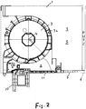
- the in the Fig. 2 differs from the first only in that the second, downwardly projecting outer wall II is missing, so that the base body 1 has an L-shaped cross section.
Landscapes
- Engineering & Computer Science (AREA)
- Structural Engineering (AREA)
- Architecture (AREA)
- Civil Engineering (AREA)
- Operating, Guiding And Securing Of Roll- Type Closing Members (AREA)
Description
- Die Erfindung betrifft einen Rollladenkasten mit einem Grundkörper in Profilform aus stabilem Kunststoffschaum mit U-förmigem oder L-förmigem, nach unten offenen Querschnitt, wobei der nach unten offene, den Rollladenwickel aufnehmende Innenraum des Grundkörpers auf der dem Gebäude zugewandten Seite durch eine nach unten ragende innere Wand begrenzt ist.
- Rollladenkästen nehmen einen Rollladenwickel auf, dessen Rollladen an der Außenseite eines Fensters oder einer Tür heruntergefahren wird. Hierbei ist der Rollladenkasten in einer Wandausnehmung befestigt, die sich oberhalb des Fensters/der Tür befindet. Dabei muss die Tiefe des Rollladenkastens der Wandstärke und der Tiefe der Wandausnehmung angepasst sein, damit der Rollladenkasten außen bündig abschließt. Ferner muss ein sauberer Abschluss der Unterseite des Rollladenkastens mit dem Wandputz geschaffen werden. Diese Anforderungen führen zu einem erheblichen Arbeits-, Material und Zeitaufwand.
- Die
DE 20 2009 002 913 U1 offenbart einen Rollladenkasten aus Schaumstoffmaterial, der auf der dem Gebäude zugewandten Seite eine nach unten ragende Innenbacken aufweist. An der Unterseite der Innenbacken ist eine dünne tragende Platte angeordnet. DieDE 20 2017 104 158 U1 offenbart einen Rollladenkasten gemäß dem Oberbegriff des Anspruchs 1. - Aufgabe der Erfindung ist es, einen Rollladenkasten der eingangs genannten Art so zu verbessern, dass die Montage- und Anpassarbeiten in der Wandausnehmung vereinfacht und erleichtert sind, wobei ein sicherer und exakter Halt des Anschlussprofils am Rollladenkasten gewährleistet ist.
- Diese Aufgabe wird erfindungsgemäß durch einen Rollladenkasten gemäß dem Anspruch 1 gelöst.
- An der Unterseite der inneren Wand ist ein waagerechtes, plattenförmiges Abschlussprofil befestigt, dessen Breite der Breite der inneren Wand und des Putzes entspricht, an dem, dem Gebäude zugewandten Ende des Abschlussprofils sitzt ein Putzanschlussprofil parallel zur Längserstreckung des Grundkörpers auf, und an dem, dem Rollladenwickel zugewandten Ende des Abschlussprofils ist ein zum Putzanschlussprofil paralleles Rastprofil angeformt, das an einem parallelen, waagerechten Aluminiumprofil einrastend gehalten ist, das in der inneren Wand gehalten ist.
- Die erfindungsgemäße Konstruktion bietet die Möglichkeit, die Kastentiefe flexibel innen nach der jeweiligen Wandstärke individuell anzupassen und mit einem Putzanschlussprofil einen sauberen Übergang von der Sturzunterseite zum Innenputz herzustellen. Mit dieser Rollladenkastenkonstruktion besteht die Möglichkeit, die Unterseite innen bis zur Sturzecke mit Abschlussprofilen in PVC zu schließen, mit dem Putzanschluss wandseitig abzudecken und eine Anbindung zum Putz herzustellen.
- Der Putzer braucht keine waagerechte Eckschutzschiene zu setzen.
- Der Putzanschluss erfolgt über das Profil, das mit eingeputzt wird.
- Der Rollladenkasten kann jeder Wandstärke individuell angepasst werden.
- Das untere Abschlussprofil ist in verschiedenen Breiten verfügbar, kann in der Breite auf die vorhandene Wandstärke zugeschnitten werden und wird mit dem Putzanschlussprofil nach innen abgedeckt.
- Ein sicherer und exakter Halt des Abschlussprofils am Rollladenkasten ist dadurch gegeben, dass an dem, dem Rollladenwickel zugewandten Ende des Abschlussprofils ein zum Putzanschlussprofil paralleles Rastprofil angeformt ist, das an einem parallelen, waagerechten Aluminiumprofil einrastend gehalten ist, das in der inneren Wand gehalten ist.
- Bei U-förmigem Querschnitt ist der Innenraum des Grundkörpers auf der dem Gebäude abgewandten Seite durch eine erste, nach unten ragende äußere Wand begrenzt, wobei die innere Wand eine größere Breite bzw. Tiefe aufweist als die der äußeren Wand.
- Vorzugsweise wird vorgeschlagen, dass das Abschlussprofil eine Hohlkammerplatte aus Kunststoff ist, so dass bei hoher Stabilität und geringem Gewicht das Abschlussprofil leicht auf die gewünschte Länge gekürzt werden kann.
- Die Putzanbindung wird erleichtert, wenn an dem freien inneren Ende des Putzanschlussprofils ein Gewebeanschlussband für die Verbindung mit dem Putz befestigt ist.
- Zwei Ausführungsbeispiele des erfindungsgemäßen Rollladenkastens sind in den Zeichnungen in senkrechten Querschnitten dargestellt. Es zeigen
- Fig. 1
- den Kastengrundkörper mit U-förmigem Querschnitt,
- Fig. 2
- den Kastengrundkörper mit L-förmigen Querschnitt.
- Der Rollladenkasten ist üblicherweise in einer Wandausnehmung oberhalb eines Fensters oder einer Tür befestigt und weist einen Grundkörper 1 in Profilform aus stabilem Kunststoffschaum S (vorzugsweise geschäumtes Polystyrol) auf. Hierbei weist das Grundkörperprofil in der in
Fig. 1 dargestellten Ausführung einen U-förmigen, nach unten offenen Querschnitt auf mit zwei nach unten ragenden Wänden I, II, die die U-Schenkel bilden und zwischen sich einen nach unten offenen Innenraum 2 bilden, der den Rollladenwickel 3 mit seinem Wickelgehäuse 3a aufnimmt. Das Grundkörperprofil erstreckt sich damit parallel zur Achse 4 des Rollladenwickels 3. Eine ähnliche Profilform des Grundkörpers ist aus derDE 10 2017 001 917 A ersichtlich. - Beim erfindungsgemäßen Rollladenkasten weist die dem Gebäude zugewandte und in der Wandausnehmung tief einliegende innere Wand I eine größere Breite (bzw. Tiefe) B1 auf als die Breite (Tiefe) B2 der äußeren Wand II. Hierbei ist die waagerechte Unterseite und damit das untere Ende der inneren Wand I durch ein Abschlussprofil 5 abgedeckt, das sich über die Breite und Länge der Unterseite erstreckt, und von einer Kunststoff-Hohlkammerplatte gebildet ist, deren Kammern parallel zur Rollladenkasten-Längserstreckung und zur Achse 4 des Wickels 3 verlaufen. Hierbei steht das Abschlussprofil 5 zum Gebäude hin über die Innenseite der inneren Wand I hinaus und kann in diesem vorstehenden Bereich entsprechend den örtlichen Gegebenheiten gekürzt werden.
- Auf dem freien Ende des Abschlussprofils 5 ist ein Putzanschlussprofil 6 längs befestigt, das aus Kunststoff besteht und einen sauberen Putzanschluss schafft. Vorzugsweise ist an dem freien inneren Ende des Putzanschlussprofils 6 ein paralleles Gewebeanschlussband für die Verbindung mit dem Putz befestigt.
- An dem, den Rollladenwickel zugewandten Ende des Abschlussprofils 5 ist ein zum Putzanschlussprofil 6 paralleles Rastprofil 8 angeformt, das an einem parallelen, waagerechten Aluminiumprofil 7 einrastend gehalten ist, das in der inneren Wand I gehalten ist. Hierbei ist das Aluminiumprofil 7 durch den Schaum S des Grundkörpers gehalten.
- An der Unterseite der äußeren Wand II ist ein weiteres Abschlussprofil 9 befestigt und an der Unterseite des Grundkörpers ist das obere waagerechte Profil 10 eines Fensters oder eines Türrahmens angeordnet. Ferner ist der Innenraum 2 an seiner Unterseite durch eine waagerechte Revisionsplatte 11 geschlossen.
- Die in der
Fig. 2 dargestellte zweite Ausführung unterscheidet sich von der ersten nur dadurch, dass die zweite, nach unten ragende äußere Wand II fehlt, so dass der Grundkörper 1 einen L-förmigen Querschnitt aufweist.
Claims (4)
- Rollladenkasten mit einem Grundkörper (1) in Profilform aus stabilem Kunststoffschaum mit U-förmigem oder L-förmigem, nach unten offenen Querschnitt, wobei der nach unten offene, den Rollladenwickel aufnehmende Innenraum (2) des Grundkörpers auf der dem Gebäude zugewandten Seite durch eine nach unten ragende innere Wand (I) begrenzt ist, wobei an der Unterseite der inneren Wand (I) ein waagerechtes, plattenförmiges Abschlussprofil (5) befestigt ist, und wobei an dem, dem Gebäude zugewandten Ende des Abschlussprofils (5) ein Putzanschlussprofil (6) parallel zur Längserstreckung des Grundkörpers aufsitzt, dadurch gekennzeichnet,- dass die Breite des Abschlussprofils (5) der Breite der inneren Wand (I) und eines Putzes entspricht, und- dass an dem, dem Rollladenwickel zugewandten Ende des Abschlussprofils (5) ein zum Putzanschlussprofil (6) paralleles Rastprofil angeformt ist, das an einem parallelen, waagerechten Aluminiumprofil (7) einrastend gehalten ist, das in der inneren Wand (I) gehalten ist.
- Rollladenkasten nach Anspruch 1, dadurch gekennzeichnet, dass bei U-förmigem Querschnitt der Innenraum (2) des Grundkörpers auf der dem Gebäude abgewandten Seite durch eine erste, nach unten ragende äußere Wand (II) begrenzt ist, wobei die innere Wand (I) eine größere Breite bzw. Tiefe (B1) aufweist als die (B2) der äußeren Wand.
- Rollladenkasten nach Anspruch 1 oder 2, dadurch gekennzeichnet, dass das Abschlussprofil (5) eine Hohlkammerplatte aus Kunststoff ist.
- Rollladenkasten nach einem der vorherigen Ansprüche, dadurch gekennzeichnet, dass an dem freien inneren Ende des Putzanschlussprofils (6) ein Gewebeanschlussband für die Verbindung mit dem Putz befestigt ist.
Priority Applications (1)
| Application Number | Priority Date | Filing Date | Title |
|---|---|---|---|
| EP18000034.1A EP3412859B1 (de) | 2018-01-17 | 2018-01-17 | Rollladenkasten |
Applications Claiming Priority (1)
| Application Number | Priority Date | Filing Date | Title |
|---|---|---|---|
| EP18000034.1A EP3412859B1 (de) | 2018-01-17 | 2018-01-17 | Rollladenkasten |
Publications (2)
| Publication Number | Publication Date |
|---|---|
| EP3412859A1 EP3412859A1 (de) | 2018-12-12 |
| EP3412859B1 true EP3412859B1 (de) | 2020-05-27 |
Family
ID=61007443
Family Applications (1)
| Application Number | Title | Priority Date | Filing Date |
|---|---|---|---|
| EP18000034.1A Active EP3412859B1 (de) | 2018-01-17 | 2018-01-17 | Rollladenkasten |
Country Status (1)
| Country | Link |
|---|---|
| EP (1) | EP3412859B1 (de) |
Family Cites Families (3)
| Publication number | Priority date | Publication date | Assignee | Title |
|---|---|---|---|---|
| DE202005007937U1 (de) * | 2005-05-17 | 2005-10-13 | Schmitz, Dirk | Rollladenkastensystem mit einem Rollladenkasten und wenigstens einem Putzträgerflächenelement |
| DE202008003147U1 (de) * | 2008-03-05 | 2008-06-26 | Kunststoffwerk Katzbach Gmbh & Co. Kg | Rollladenkasten |
| DE202017104158U1 (de) * | 2017-07-12 | 2017-08-04 | Kunststoffwerk Katzbach Gmbh & Co. Kg | Rollladenkasten aus einem Schaumkunststoffmaterial |
-
2018
- 2018-01-17 EP EP18000034.1A patent/EP3412859B1/de active Active
Non-Patent Citations (1)
| Title |
|---|
| None * |
Also Published As
| Publication number | Publication date |
|---|---|
| EP3412859A1 (de) | 2018-12-12 |
Similar Documents
| Publication | Publication Date | Title |
|---|---|---|
| EP0003042A1 (de) | Rahmenprofil für einen Schiebeflügel | |
| EP3438395B1 (de) | Fensterrahmensystem | |
| DE2715909A1 (de) | Rolladen-fensterelement | |
| EP2843179A1 (de) | Rollladenkastenbaugruppe, sowie Kastenwandprofil und Zusatzprofil dafür | |
| DE69404247T2 (de) | Rolladenkasten | |
| EP3412859A1 (de) | Rollladenkasten | |
| DE20200627U1 (de) | Flexibles Kastensystem | |
| DE2934940C2 (de) | Außenfenster zum Verdecken einer Öffnung in einer mit einer Außenverkleidung versehenen Gebäudewand | |
| DE2939028C2 (de) | Fertigbau-Wandelement | |
| DE19959736A1 (de) | Rolladen-Aufsatzkasten | |
| DE3346442C2 (de) | ||
| DE102013112644A1 (de) | Dämm- und Montageelement sowie Gebäudefenster oder Gebäudetür | |
| DE8622304U1 (de) | Rolladenkasten | |
| DE4240846A1 (de) | Tür | |
| DE2445285A1 (de) | Fenster | |
| DE2416567A1 (de) | Vorrichtung zur erneuerung von fenstern | |
| DE20308239U1 (de) | Profilelement | |
| DE2711469A1 (de) | Bauelement und zugehoerige halteleiste | |
| DE2425456C3 (de) | Kunststoffrahmen zum Verkleiden von alten Fenster- und Türstöcken | |
| EP0230998A2 (de) | Torblatt mit Belüftungsöffnungen | |
| CH663058A5 (de) | Aluminium-fensterbank. | |
| DE10011576A1 (de) | Fenster- oder Türrahmen für Container o. dgl. | |
| DE29811577U1 (de) | Wandkasten für Gebäudeaußenmauern | |
| DE3447960C2 (de) | ||
| DE19642422B4 (de) | Rolladenkasten für Rundbögen |
Legal Events
| Date | Code | Title | Description |
|---|---|---|---|
| PUAI | Public reference made under article 153(3) epc to a published international application that has entered the european phase |
Free format text: ORIGINAL CODE: 0009012 |
|
| STAA | Information on the status of an ep patent application or granted ep patent |
Free format text: STATUS: THE APPLICATION HAS BEEN PUBLISHED |
|
| AK | Designated contracting states |
Kind code of ref document: A1 Designated state(s): AL AT BE BG CH CY CZ DE DK EE ES FI FR GB GR HR HU IE IS IT LI LT LU LV MC MK MT NL NO PL PT RO RS SE SI SK SM TR |
|
| AX | Request for extension of the european patent |
Extension state: BA ME |
|
| STAA | Information on the status of an ep patent application or granted ep patent |
Free format text: STATUS: REQUEST FOR EXAMINATION WAS MADE |
|
| 17P | Request for examination filed |
Effective date: 20190121 |
|
| RBV | Designated contracting states (corrected) |
Designated state(s): AL AT BE BG CH CY CZ DE DK EE ES FI FR GB GR HR HU IE IS IT LI LT LU LV MC MK MT NL NO PL PT RO RS SE SI SK SM TR |
|
| GRAP | Despatch of communication of intention to grant a patent |
Free format text: ORIGINAL CODE: EPIDOSNIGR1 |
|
| STAA | Information on the status of an ep patent application or granted ep patent |
Free format text: STATUS: GRANT OF PATENT IS INTENDED |
|
| INTG | Intention to grant announced |
Effective date: 20200103 |
|
| GRAS | Grant fee paid |
Free format text: ORIGINAL CODE: EPIDOSNIGR3 |
|
| GRAA | (expected) grant |
Free format text: ORIGINAL CODE: 0009210 |
|
| STAA | Information on the status of an ep patent application or granted ep patent |
Free format text: STATUS: THE PATENT HAS BEEN GRANTED |
|
| AK | Designated contracting states |
Kind code of ref document: B1 Designated state(s): AL AT BE BG CH CY CZ DE DK EE ES FI FR GB GR HR HU IE IS IT LI LT LU LV MC MK MT NL NO PL PT RO RS SE SI SK SM TR |
|
| REG | Reference to a national code |
Ref country code: GB Ref legal event code: FG4D Free format text: NOT ENGLISH |
|
| REG | Reference to a national code |
Ref country code: CH Ref legal event code: EP |
|
| REG | Reference to a national code |
Ref country code: AT Ref legal event code: REF Ref document number: 1274726 Country of ref document: AT Kind code of ref document: T Effective date: 20200615 |
|
| REG | Reference to a national code |
Ref country code: DE Ref legal event code: R096 Ref document number: 502018001494 Country of ref document: DE |
|
| REG | Reference to a national code |
Ref country code: LT Ref legal event code: MG4D |
|
| PG25 | Lapsed in a contracting state [announced via postgrant information from national office to epo] |
Ref country code: SE Free format text: LAPSE BECAUSE OF FAILURE TO SUBMIT A TRANSLATION OF THE DESCRIPTION OR TO PAY THE FEE WITHIN THE PRESCRIBED TIME-LIMIT Effective date: 20200527 Ref country code: IS Free format text: LAPSE BECAUSE OF FAILURE TO SUBMIT A TRANSLATION OF THE DESCRIPTION OR TO PAY THE FEE WITHIN THE PRESCRIBED TIME-LIMIT Effective date: 20200927 Ref country code: NO Free format text: LAPSE BECAUSE OF FAILURE TO SUBMIT A TRANSLATION OF THE DESCRIPTION OR TO PAY THE FEE WITHIN THE PRESCRIBED TIME-LIMIT Effective date: 20200827 Ref country code: GR Free format text: LAPSE BECAUSE OF FAILURE TO SUBMIT A TRANSLATION OF THE DESCRIPTION OR TO PAY THE FEE WITHIN THE PRESCRIBED TIME-LIMIT Effective date: 20200828 Ref country code: FI Free format text: LAPSE BECAUSE OF FAILURE TO SUBMIT A TRANSLATION OF THE DESCRIPTION OR TO PAY THE FEE WITHIN THE PRESCRIBED TIME-LIMIT Effective date: 20200527 Ref country code: LT Free format text: LAPSE BECAUSE OF FAILURE TO SUBMIT A TRANSLATION OF THE DESCRIPTION OR TO PAY THE FEE WITHIN THE PRESCRIBED TIME-LIMIT Effective date: 20200527 Ref country code: PT Free format text: LAPSE BECAUSE OF FAILURE TO SUBMIT A TRANSLATION OF THE DESCRIPTION OR TO PAY THE FEE WITHIN THE PRESCRIBED TIME-LIMIT Effective date: 20200928 |
|
| REG | Reference to a national code |
Ref country code: NL Ref legal event code: MP Effective date: 20200527 |
|
| PG25 | Lapsed in a contracting state [announced via postgrant information from national office to epo] |
Ref country code: LV Free format text: LAPSE BECAUSE OF FAILURE TO SUBMIT A TRANSLATION OF THE DESCRIPTION OR TO PAY THE FEE WITHIN THE PRESCRIBED TIME-LIMIT Effective date: 20200527 Ref country code: HR Free format text: LAPSE BECAUSE OF FAILURE TO SUBMIT A TRANSLATION OF THE DESCRIPTION OR TO PAY THE FEE WITHIN THE PRESCRIBED TIME-LIMIT Effective date: 20200527 Ref country code: RS Free format text: LAPSE BECAUSE OF FAILURE TO SUBMIT A TRANSLATION OF THE DESCRIPTION OR TO PAY THE FEE WITHIN THE PRESCRIBED TIME-LIMIT Effective date: 20200527 Ref country code: BG Free format text: LAPSE BECAUSE OF FAILURE TO SUBMIT A TRANSLATION OF THE DESCRIPTION OR TO PAY THE FEE WITHIN THE PRESCRIBED TIME-LIMIT Effective date: 20200827 |
|
| PG25 | Lapsed in a contracting state [announced via postgrant information from national office to epo] |
Ref country code: NL Free format text: LAPSE BECAUSE OF FAILURE TO SUBMIT A TRANSLATION OF THE DESCRIPTION OR TO PAY THE FEE WITHIN THE PRESCRIBED TIME-LIMIT Effective date: 20200527 Ref country code: AL Free format text: LAPSE BECAUSE OF FAILURE TO SUBMIT A TRANSLATION OF THE DESCRIPTION OR TO PAY THE FEE WITHIN THE PRESCRIBED TIME-LIMIT Effective date: 20200527 |
|
| PG25 | Lapsed in a contracting state [announced via postgrant information from national office to epo] |
Ref country code: ES Free format text: LAPSE BECAUSE OF FAILURE TO SUBMIT A TRANSLATION OF THE DESCRIPTION OR TO PAY THE FEE WITHIN THE PRESCRIBED TIME-LIMIT Effective date: 20200527 Ref country code: SM Free format text: LAPSE BECAUSE OF FAILURE TO SUBMIT A TRANSLATION OF THE DESCRIPTION OR TO PAY THE FEE WITHIN THE PRESCRIBED TIME-LIMIT Effective date: 20200527 Ref country code: DK Free format text: LAPSE BECAUSE OF FAILURE TO SUBMIT A TRANSLATION OF THE DESCRIPTION OR TO PAY THE FEE WITHIN THE PRESCRIBED TIME-LIMIT Effective date: 20200527 Ref country code: EE Free format text: LAPSE BECAUSE OF FAILURE TO SUBMIT A TRANSLATION OF THE DESCRIPTION OR TO PAY THE FEE WITHIN THE PRESCRIBED TIME-LIMIT Effective date: 20200527 Ref country code: IT Free format text: LAPSE BECAUSE OF FAILURE TO SUBMIT A TRANSLATION OF THE DESCRIPTION OR TO PAY THE FEE WITHIN THE PRESCRIBED TIME-LIMIT Effective date: 20200527 Ref country code: CZ Free format text: LAPSE BECAUSE OF FAILURE TO SUBMIT A TRANSLATION OF THE DESCRIPTION OR TO PAY THE FEE WITHIN THE PRESCRIBED TIME-LIMIT Effective date: 20200527 Ref country code: RO Free format text: LAPSE BECAUSE OF FAILURE TO SUBMIT A TRANSLATION OF THE DESCRIPTION OR TO PAY THE FEE WITHIN THE PRESCRIBED TIME-LIMIT Effective date: 20200527 |
|
| PG25 | Lapsed in a contracting state [announced via postgrant information from national office to epo] |
Ref country code: SK Free format text: LAPSE BECAUSE OF FAILURE TO SUBMIT A TRANSLATION OF THE DESCRIPTION OR TO PAY THE FEE WITHIN THE PRESCRIBED TIME-LIMIT Effective date: 20200527 Ref country code: PL Free format text: LAPSE BECAUSE OF FAILURE TO SUBMIT A TRANSLATION OF THE DESCRIPTION OR TO PAY THE FEE WITHIN THE PRESCRIBED TIME-LIMIT Effective date: 20200527 |
|
| REG | Reference to a national code |
Ref country code: DE Ref legal event code: R097 Ref document number: 502018001494 Country of ref document: DE |
|
| PLBE | No opposition filed within time limit |
Free format text: ORIGINAL CODE: 0009261 |
|
| STAA | Information on the status of an ep patent application or granted ep patent |
Free format text: STATUS: NO OPPOSITION FILED WITHIN TIME LIMIT |
|
| 26N | No opposition filed |
Effective date: 20210302 |
|
| PG25 | Lapsed in a contracting state [announced via postgrant information from national office to epo] |
Ref country code: SI Free format text: LAPSE BECAUSE OF FAILURE TO SUBMIT A TRANSLATION OF THE DESCRIPTION OR TO PAY THE FEE WITHIN THE PRESCRIBED TIME-LIMIT Effective date: 20200527 |
|
| PG25 | Lapsed in a contracting state [announced via postgrant information from national office to epo] |
Ref country code: MC Free format text: LAPSE BECAUSE OF FAILURE TO SUBMIT A TRANSLATION OF THE DESCRIPTION OR TO PAY THE FEE WITHIN THE PRESCRIBED TIME-LIMIT Effective date: 20200527 |
|
| REG | Reference to a national code |
Ref country code: CH Ref legal event code: PL |
|
| PG25 | Lapsed in a contracting state [announced via postgrant information from national office to epo] |
Ref country code: LU Free format text: LAPSE BECAUSE OF NON-PAYMENT OF DUE FEES Effective date: 20210117 |
|
| REG | Reference to a national code |
Ref country code: BE Ref legal event code: MM Effective date: 20210131 |
|
| PG25 | Lapsed in a contracting state [announced via postgrant information from national office to epo] |
Ref country code: CH Free format text: LAPSE BECAUSE OF NON-PAYMENT OF DUE FEES Effective date: 20210131 Ref country code: LI Free format text: LAPSE BECAUSE OF NON-PAYMENT OF DUE FEES Effective date: 20210131 |
|
| PG25 | Lapsed in a contracting state [announced via postgrant information from national office to epo] |
Ref country code: IE Free format text: LAPSE BECAUSE OF NON-PAYMENT OF DUE FEES Effective date: 20210117 |
|
| PG25 | Lapsed in a contracting state [announced via postgrant information from national office to epo] |
Ref country code: BE Free format text: LAPSE BECAUSE OF NON-PAYMENT OF DUE FEES Effective date: 20210131 |
|
| GBPC | Gb: european patent ceased through non-payment of renewal fee |
Effective date: 20220117 |
|
| PG25 | Lapsed in a contracting state [announced via postgrant information from national office to epo] |
Ref country code: GB Free format text: LAPSE BECAUSE OF NON-PAYMENT OF DUE FEES Effective date: 20220117 |
|
| PG25 | Lapsed in a contracting state [announced via postgrant information from national office to epo] |
Ref country code: CY Free format text: LAPSE BECAUSE OF FAILURE TO SUBMIT A TRANSLATION OF THE DESCRIPTION OR TO PAY THE FEE WITHIN THE PRESCRIBED TIME-LIMIT Effective date: 20200527 |
|
| PG25 | Lapsed in a contracting state [announced via postgrant information from national office to epo] |
Ref country code: HU Free format text: LAPSE BECAUSE OF FAILURE TO SUBMIT A TRANSLATION OF THE DESCRIPTION OR TO PAY THE FEE WITHIN THE PRESCRIBED TIME-LIMIT; INVALID AB INITIO Effective date: 20180117 |
|
| REG | Reference to a national code |
Ref country code: AT Ref legal event code: MM01 Ref document number: 1274726 Country of ref document: AT Kind code of ref document: T Effective date: 20230117 |
|
| PG25 | Lapsed in a contracting state [announced via postgrant information from national office to epo] |
Ref country code: AT Free format text: LAPSE BECAUSE OF NON-PAYMENT OF DUE FEES Effective date: 20230117 |
|
| PG25 | Lapsed in a contracting state [announced via postgrant information from national office to epo] |
Ref country code: MK Free format text: LAPSE BECAUSE OF FAILURE TO SUBMIT A TRANSLATION OF THE DESCRIPTION OR TO PAY THE FEE WITHIN THE PRESCRIBED TIME-LIMIT Effective date: 20200527 Ref country code: AT Free format text: LAPSE BECAUSE OF NON-PAYMENT OF DUE FEES Effective date: 20230117 |
|
| PG25 | Lapsed in a contracting state [announced via postgrant information from national office to epo] |
Ref country code: MT Free format text: LAPSE BECAUSE OF FAILURE TO SUBMIT A TRANSLATION OF THE DESCRIPTION OR TO PAY THE FEE WITHIN THE PRESCRIBED TIME-LIMIT Effective date: 20200527 |
|
| PG25 | Lapsed in a contracting state [announced via postgrant information from national office to epo] |
Ref country code: TR Free format text: LAPSE BECAUSE OF FAILURE TO SUBMIT A TRANSLATION OF THE DESCRIPTION OR TO PAY THE FEE WITHIN THE PRESCRIBED TIME-LIMIT Effective date: 20200527 |
|
| PGFP | Annual fee paid to national office [announced via postgrant information from national office to epo] |
Ref country code: DE Payment date: 20260120 Year of fee payment: 9 |
|
| PGFP | Annual fee paid to national office [announced via postgrant information from national office to epo] |
Ref country code: AT Payment date: 20260410 Year of fee payment: 5 |
|
| PGFP | Annual fee paid to national office [announced via postgrant information from national office to epo] |
Ref country code: FR Payment date: 20260121 Year of fee payment: 9 |