EP3412865B1 - Système modulaire de fabrication d'une pompe à vis - Google Patents
Système modulaire de fabrication d'une pompe à vis Download PDFInfo
- Publication number
- EP3412865B1 EP3412865B1 EP18167759.2A EP18167759A EP3412865B1 EP 3412865 B1 EP3412865 B1 EP 3412865B1 EP 18167759 A EP18167759 A EP 18167759A EP 3412865 B1 EP3412865 B1 EP 3412865B1
- Authority
- EP
- European Patent Office
- Prior art keywords
- housing
- spindle
- running
- component
- pump
- Prior art date
- Legal status (The legal status is an assumption and is not a legal conclusion. Google has not performed a legal analysis and makes no representation as to the accuracy of the status listed.)
- Active
Links
Images



Classifications
-
- F—MECHANICAL ENGINEERING; LIGHTING; HEATING; WEAPONS; BLASTING
- F04—POSITIVE - DISPLACEMENT MACHINES FOR LIQUIDS; PUMPS FOR LIQUIDS OR ELASTIC FLUIDS
- F04C—ROTARY-PISTON, OR OSCILLATING-PISTON, POSITIVE-DISPLACEMENT MACHINES FOR LIQUIDS; ROTARY-PISTON, OR OSCILLATING-PISTON, POSITIVE-DISPLACEMENT PUMPS
- F04C2/00—Rotary-piston machines or pumps
- F04C2/08—Rotary-piston machines or pumps of intermeshing-engagement type, i.e. with engagement of co-operating members similar to that of toothed gearing
- F04C2/12—Rotary-piston machines or pumps of intermeshing-engagement type, i.e. with engagement of co-operating members similar to that of toothed gearing of other than internal-axis type
- F04C2/14—Rotary-piston machines or pumps of intermeshing-engagement type, i.e. with engagement of co-operating members similar to that of toothed gearing of other than internal-axis type with toothed rotary pistons
- F04C2/16—Rotary-piston machines or pumps of intermeshing-engagement type, i.e. with engagement of co-operating members similar to that of toothed gearing of other than internal-axis type with toothed rotary pistons with helical teeth, e.g. chevron-shaped, screw type
-
- F—MECHANICAL ENGINEERING; LIGHTING; HEATING; WEAPONS; BLASTING
- F04—POSITIVE - DISPLACEMENT MACHINES FOR LIQUIDS; PUMPS FOR LIQUIDS OR ELASTIC FLUIDS
- F04C—ROTARY-PISTON, OR OSCILLATING-PISTON, POSITIVE-DISPLACEMENT MACHINES FOR LIQUIDS; ROTARY-PISTON, OR OSCILLATING-PISTON, POSITIVE-DISPLACEMENT PUMPS
- F04C11/00—Combinations of two or more machines or pumps, each being of rotary-piston or oscillating-piston type; Pumping installations
- F04C11/001—Combinations of two or more machines or pumps, each being of rotary-piston or oscillating-piston type; Pumping installations of similar working principle
-
- F—MECHANICAL ENGINEERING; LIGHTING; HEATING; WEAPONS; BLASTING
- F04—POSITIVE - DISPLACEMENT MACHINES FOR LIQUIDS; PUMPS FOR LIQUIDS OR ELASTIC FLUIDS
- F04C—ROTARY-PISTON, OR OSCILLATING-PISTON, POSITIVE-DISPLACEMENT MACHINES FOR LIQUIDS; ROTARY-PISTON, OR OSCILLATING-PISTON, POSITIVE-DISPLACEMENT PUMPS
- F04C2240/00—Components
- F04C2240/20—Rotors
-
- F—MECHANICAL ENGINEERING; LIGHTING; HEATING; WEAPONS; BLASTING
- F04—POSITIVE - DISPLACEMENT MACHINES FOR LIQUIDS; PUMPS FOR LIQUIDS OR ELASTIC FLUIDS
- F04C—ROTARY-PISTON, OR OSCILLATING-PISTON, POSITIVE-DISPLACEMENT MACHINES FOR LIQUIDS; ROTARY-PISTON, OR OSCILLATING-PISTON, POSITIVE-DISPLACEMENT PUMPS
- F04C2240/00—Components
- F04C2240/30—Casings or housings
-
- F—MECHANICAL ENGINEERING; LIGHTING; HEATING; WEAPONS; BLASTING
- F04—POSITIVE - DISPLACEMENT MACHINES FOR LIQUIDS; PUMPS FOR LIQUIDS OR ELASTIC FLUIDS
- F04C—ROTARY-PISTON, OR OSCILLATING-PISTON, POSITIVE-DISPLACEMENT MACHINES FOR LIQUIDS; ROTARY-PISTON, OR OSCILLATING-PISTON, POSITIVE-DISPLACEMENT PUMPS
- F04C2240/00—Components
- F04C2240/70—Use of multiplicity of similar components; Modular construction
Definitions
- the invention relates to a modular system for producing a screw pump.
- Such screw spindle pumps are used, for example, to pump oils or other more or less lubricating liquids.
- a screw spindle pump consists of a housing and a drive spindle accommodated therein, which meshes with one or two running spindles accommodated on the housing side.
- the spindles form sealed chambers due to the interlocking thread flanks. If the drive spindle is rotated, the running spindles also rotate automatically. This means that the sucked liquid in the chambers is conveyed axially and continuously from the suction side to the pressure side of the pump and is released there via the outlet.
- the publication US2014/099225 A1 discloses a modular multistage screw pump.
- Such screw spindle pumps are known in different designs for specific pressure levels, for example low pressure, medium pressure, high pressure, ultra-high pressure, etc.
- the corresponding components are manufactured separately for each pressure level and designed in the required length. This means that a pump body of the appropriate length as well as appropriately sized drive and running spindles are manufactured for each pressure stage. Both the pump body and the spindles are made in one piece.
- the required overall length and thus the design of the screw spindle pump varies depending on the requirements with regard to the desired differential pressure, the viscosity of the fluid to be pumped, etc. Particularly with larger or longer pumps, the machining of the corresponding components becomes more difficult due to the increasing component length and thus the machining length, which Manufacturing such screw spindle pumps is complex.
- the invention is therefore based on the problem of specifying an improved screw spindle design.
- the modular system according to the invention for configuring a screw spindle pump makes it possible to produce a screw spindle pump with a selectable pump length solely from standardized components that are the same for all pump sizes that can be produced.
- the only non-modular pump component is the drive spindle, which must be manufactured as a one-piece component according to the desired pump size.
- the modular system includes a housing base component. This has the fluid inlet, i.e. the suction side, and forms a base pump chamber, which at the same time forms the smallest pump chamber of the smallest pump size that can be produced.
- the system further comprises a housing pressure component which forms the pressure chamber and which has a fluid outlet in order to release the suctioned and delivered fluid back out of the pump with the corresponding pump pressure.
- the drive spindle is mounted and sealed in this housing pressure component.
- the system includes a housing cover that can be arranged on the housing base component and which closes the housing component on this side (on the opposite side it is closed via the housing pressure component).
- the running spindle or spindles are usually supported hydrostatically on the housing cover for axial thrust compensation.
- the housing base component, the housing pressure component and the housing cover are the three components that, when it comes to the configuration of the housing, are installed in every pump size that can be manufactured.
- the system includes a plurality of identical intermediate housing components, which can be installed in any number between the housing base component and the housing pressure component. These intermediate housing components therefore extend the base pump chamber by the corresponding length of one or more additional pump chambers, depending on how many of these identical intermediate housing components are placed between the housing base component and the housing pressure component.
- each housing intermediate component has corresponding bores for receiving the continuous drive spindle and the running spindles.
- the smallest pump size is defined in its working length by the housing base component and the housing pressure component attached to it.
- the next larger pump size then has one between the housing base component and Housing pressure component placed on the housing intermediate component, so that the pump room is formed from the base pump room and an extending additional pump room.
- the next pump size is characterized by two intermediate housing components so that the pump chamber is defined by the basic pump chamber and two additional pump chambers that extend it. In this way, by continuously integrating additional intermediate housing components, the length of the pump housing can be continuously expanded, up to a maximum pump length, which is ultimately defined by the maximum producible length of the drive spindle, which is manufactured in one piece as described.
- the one or two running spindles are also constructed modularly from standardized running spindle elements.
- the system comprises a plurality of running spindle elements and, among these, one or two running spindle base elements that can be arranged in the housing base component.
- This or these barrel spindle base elements are the spindle elements to be used with every pump size.
- Their length is dimensioned according to the spindle bore length of the housing base component and, when installed, is arranged in the housing base component, i.e. the base pump room. With the smallest pump size, the or each running spindle is formed by only one running spindle base element.
- the respective running spindle must also be lengthened. This is done via a plurality of identical running spindle extension elements, which are each arranged in the housing intermediate component or components, depending on how many are arranged between the housing base component and the housing pressure component.
- the number of intermediate housing components corresponds to the number of running spindle extension elements per running spindle.
- the running spindle can also be modularly configured to any length corresponding to the length of the pump housing.
- the modular system according to the invention therefore consists of a series of standardized components, namely the standardized housing components and the standardized running spindle elements.
- Every pump that can be produced always has a housing base component, a housing cover, a housing pressure component and a running spindle base element as well as of course the corresponding one-piece drive spindle that is manufactured to suit pump types.
- the possibility of extending the pump is made possible via the standardized, identical housing intermediate components as well as the standardized, identical running spindle extension elements. This makes it possible to produce screw spindle pumps of different lengths and different performance, with only the drive spindle having to be manufactured in the appropriate length for each size.
- this modular system also offers other advantages, for example with regard to the production of the corresponding components or identical parts. This is because significantly shorter components or spindle elements have to be produced compared to the one-piece parts previously known in the prior art, so that part production is simplified. At the same time, the manufacturing quality of the pump produced remains high regardless of the component length, as only short, standardized parts can be manufactured.
- the design of very long pumps, e.g. B. possible for very high pressures regardless of production, and warehousing and parts management is considerably simplified, as only the short, standardized parts, of which a large number can be produced in stock, have to be kept in stock.
- the division of the housing components and the running spindle elements is identical. This means that the parting planes of the housing components and the parting planes of the running spindle elements coincide. This applies regardless of whether the pump consists of the housing base component, the housing pressure component and only one intermediate housing component, or whether a plurality Such intermediate housing components and inevitably a plurality of running spindle extension elements are installed.
- This division identity has advantages with regard to the hydrostatic sliding bearing of the running spindle elements in the housing components.
- the running spindle elements are hydrostatically mounted at a small distance of just a few micrometers, i.e. they are slide-mounted on the bore wall of the respective housing component via a lubricating film.
- the parting plane of the running spindle elements also lies in this parting plane area.
- Appropriate measures on the part of the running spindle element configuration can ensure that the running spindle elements do not come into direct contact with the housing wall in this area, but that there is always a hydrodynamic sliding bearing.
- the running spindle extension elements and the running spindle base element(s) merely lie against one another with their flat end faces. This means that the spindle elements are not firmly connected to one another, but simply rest against one another axially, i.e. they are infinitesimally radially movable relative to one another. There is no need for a connection since the running spindle elements are in engagement with the thread of the drive spindle with their thread flanks and they are carried along here.
- the specific spindle element position can be adjusted exactly in relation to the respective bore wall of the respective housing component, after, if necessary, a minimal compensation in the micrometer range, if necessary. is possible.
- the intermediate housing components have axial through holes with a front screw head recess and axial ones in an arrangement distributed around the circumference Have threaded holes, the through holes and the threaded holes being provided in an alternating arrangement.
- This hole pattern makes it possible to connect the intermediate housing components, which are to be arranged in a correspondingly rotated position relative to one another, to one another and also to connect them to the housing base component and the housing pressure component.
- the corresponding connecting screws are passed through the through holes with the front screw head recess through the one intermediate housing component and screwed into the front axial threaded holes of the adjacent intermediate housing element. In this way, any number of intermediate housing elements can be integrated and connected to one another.
- threaded holes also makes it possible for corresponding connecting screws, which are guided through the housing pressure component, to be screwed into the adjacent intermediate housing component.
- connecting screws of the intermediate housing element adjacent to the housing base component, guided through the corresponding through holes, can be screwed into corresponding threaded holes in the housing base component.
- the housing pressure component itself can preferably consist of two housing pressure component elements that are axially connected or connectable to one another via screw connections. As stated, on the one hand, the pressure chamber and fluid outlet are provided in the housing pressure component, but on the other hand, the storage and sealing of the drive spindle is also implemented. The design of these different functional sections is easier if the housing pressure component is designed to be modular and consists of these two standardized housing pressure component elements that are identical for all sizes.
- housing pressure component for connection to the housing base component in the case of the smallest pump size or an adjacent housing intermediate element are optionally designed with front screw head recesses. This is possible with a one-piece design of the housing pressure component.
- the housing pressure component is also designed modularly from two housing pressure component elements
- a corresponding bore configuration with through holes and threaded holes in the corresponding housing pressure component elements is also suitable in this case.
- only through holes are preferably formed on the axially outer housing pressure component element, which are optionally formed with front screw head recesses, and on the axially inner housing pressure component element, in an arrangement distributed around the circumference, axial through holes with a front screw head recess and axial threaded holes are formed, the through holes and the threaded holes in are provided in an alternating arrangement.
- this configuration makes it possible to connect the axially terminal housing pressure component element with the adjacent second housing pressure component element.
- the connecting screws are passed through the through holes provided in the outer housing pressure component element and screwed into the threaded hole of the adjacent housing pressure component element.
- additional axial through-holes with a front-side screw head recess are provided.
- the connecting screws are guided through these through holes for connection to the housing base component or the adjacent housing intermediate element, which are screwed into the threaded holes there.
- a distributed, alternating arrangement of threaded holes and through holes is useful.
- the housing base component for its part, is only provided with threaded holes on both axial end faces. On the one hand, these make it possible to attach the Housing cover, which has corresponding through holes, through which corresponding connecting screws are passed, which are screwed into the threaded holes of the housing base component. From the other side, the connecting screws, which pass through either the housing pressure component or the internal housing pressure component element, or which pass through the adjacent housing intermediate element, are screwed in.
- the length of the running spindle base elements is expediently greater than the length of the running spindle extension elements.
- the housing base component forms the base pump chamber; it must be dimensioned accordingly long since the fluid inlet is also provided on it. In contrast, the intermediate housing elements and the additional pump rooms formed via them are somewhat shorter.
- the ends of the running spindle base elements arranged adjacent to the housing cover are accommodated in compensating sleeves which serve to compensate for an axial thrust.
- a usually hydrostatic axial thrust compensation takes place in the running spindle base element, for which purpose the corresponding compensating sleeves are provided, which are placed on the ends of the running spindle base elements and run with their sleeve end surfaces adjacent to the housing cover.
- the invention also relates to a pump manufactured using a modular system of the type described.
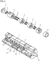
- Fig. 1 shows a modular system 1 according to the invention, the central parts of which are shown individually. The required connecting screws and the respective size-specific drive spindle are not shown.
- the modular system 1 comprises a housing cover 2, two compensating sleeves 3 (the screw spindle pumps that can be produced according to the invention have two running spindles in the example shown), a housing base component 4, two running spindle base elements 5, four intermediate housing elements 6, eight running spindle extension elements 7 and two housing pressure components 8 forming housing pressure component elements 9, 10.
- the housing base component 4, the housing intermediate elements 6 and the housing pressure component elements 9, 10 have corresponding bores on the one hand, to accommodate the drive spindle, not shown, and to store and seal it in the case of the housing pressure component 8, and to accommodate the corresponding running spindles, formed from the running spindle base elements 5 and the running spindle extension elements 7.
- the housing base component 4 has a fluid inlet 11 and forms a base pump space.
- the housing pressure component 8 has a fluid outlet 12 on the housing pressure component element 9. It also forms a pressure chamber with the housing pressure component element 9, which communicates with the fluid outlet 12.
- the intermediate housing components 6 and the running spindle extension elements 7 are identical to one another. This and the fact that for every pump size that can be produced using the modular system 1, the housing cover 2, the housing base element 4 and the housing pressure component or the housing pressure component elements 9 and 10 must always be installed, means that any pump size can be produced from corresponding identical parts.
- Fig. 2 - 5 show various from the modular system 1 according to Fig. 1 Pumps that can be produced, with the same reference numbers being used for the same components.
- Fig. 2 shows a pump 13 according to the invention in the shortest design.
- a drive spindle 14 which is the only component to be manufactured individually for each size, this consists of the housing cover 2, the housing base component 4, the two housing pressure component elements 9, 10 as well as the two running spindle base elements 5 and the two compensating sleeves 3.
- the running spindle base elements 5 are exclusively in the housing base element 4 recorded.
- the division between the housing base element 4 and the housing pressure element 8 or housing pressure element 9 is selected so that the running spindle base elements 5 end exactly at the division or parting plane.
- a connecting screw 15 which serves to connect the housing pressure component element 10 to the housing pressure component element 9.
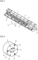
- the housing pressure component element 10 has a corresponding through hole 16 with a screw head receptacle 17, while the housing pressure component element 9 has a corresponding threaded hole 18 into which the connecting screw 15 is screwed.
- three such screw connections are implemented around the circumference.
- This view also shows the corresponding through holes 23, which pass through the housing cover 2, into which corresponding connecting screws (not shown) are inserted, which are screwed into corresponding threaded holes on the end face of the housing base element 4, also not shown.
- Fig. 3 shows a second pump 13 that can be produced from the modular system 1 in a next pump size.
- This pump 13 also consists of the housing cover 2, the housing base component 4, the two housing pressure component elements 9, 10 and the two running spindle elements 5 and the compensating sleeves 3.
- an intermediate housing component 6 is placed here between the housing base component 4 and the housing pressure component element 9, in which two running spindle extension elements 7 are also accommodated, only one of which is visible here.
- the running spindle base element 5 and the running spindle extension element 7 only lie against one another with their axial, flat end faces; they are not connected to one another. However, they are taken along in a manner known per se via the engagement of the corresponding thread flanks with the thread flanks of the drive spindle 15.
- a connecting screw 24 via which the intermediate housing component 6 is connected to the housing base component 4.
- a connecting screw 24 via which the intermediate housing component 6 is connected to the housing base component 4.
- several through holes 25 are formed with corresponding screw head receptacles 26, while the threaded holes 22 are formed on the front side of the housing base component 4, as already described.
- the corresponding connecting screws 24 are screwed into these.
- threaded holes 27 are also provided as blind holes (this applies to all threaded holes). These threaded holes 27 serve to accommodate connecting screws 19, as already mentioned Fig. 7 were described, and as they are also in Fig. 8 are shown as an example where the housing pressure component element 9 is connected to an intermediate housing component 6 via these connecting screws 19. The connecting screws 19 are screwed into the corresponding threaded holes 27, through which the component connection takes place.
- the next larger expansion stage of the pump 13 that can be produced from the modular system according to the invention shows Fig. 4 .
- the identical components are there as in pump 13 Fig. 3 provided, in addition, a further intermediate housing component 6 and two further running spindle extension elements 7 are provided here. This means that the entire pump room was again extended with the additional pump room realized by means of an intermediate housing component 6 in conjunction with the running spindle extension elements 7.
- connecting screws 28 are used, which pass through the one intermediate housing component 6 in the through holes 25 and which are recessed with their screw heads in the screw head receptacles 26.
- the connecting screws 28 are screwed into the corresponding blind threaded holes 27 on the adjacent intermediate housing element 6.
- the two intermediate housing components 6 are rotated by 180 ° relative to each other, so that the through holes 25 of one intermediate housing component 6 are aligned with the threaded holes 27 of the other intermediate housing component 6. This is possible due to the division of the through holes 25 and the threaded holes 27 by 120°.
- the division of the housing components i.e. the division of the housing base component 4 as well as the housing intermediate components 6 and the housing pressure component element 9 and the corresponding division levels the running spindle elements, i.e. the running spindle base element and the two running spindle extension elements 7, are identical or the corresponding dividing planes coincide.
- Fig. 5 finally shows a partial sectional view of a pump 13 according to the invention, starting from the modular system according to Fig. 1 maximum expansion level that can be produced.
- the same components are used as for the pump Fig. 4 as well as two additional intermediate housing components 6 and four additional running spindle additional elements 7 are provided.
- the pump room is extended by two additional additional pump rooms, formed via the additional intermediate housing elements 6, so that a maximum pump room consisting of the basic pump room and four additional pump rooms results.
- This pump 13 is the most powerful pump that provides the highest pressure, based on the in Fig. 1 number of parts shown. Theoretically, the pump can of course be extended as required, so that longer pumps can also be used Fig. 5 shown can be produced with the system according to the invention.
- the intermediate housing components 6 are in turn connected to one another via corresponding connecting screws 28, see also the view according to Fig. 8 , which shows a different cutting plane.
- the respective drive spindle 14 is the only component to be manufactured individually for the respective pump size. This is because it is a one-piece spindle, while the respective running spindles all consist modularly of the running spindle base elements 5 and the running spindle extension elements 7. As already mentioned, the running spindle base and extension elements 5, 7 are not connected to one another, rather their flat end faces merely lie against one another in order to ensure hydrodynamic sliding bearings exclusively within the respective one To enable housing section and to avoid any friction problems in the area of component transitions or parting lines.
Landscapes
- Engineering & Computer Science (AREA)
- Mechanical Engineering (AREA)
- General Engineering & Computer Science (AREA)
- Details And Applications Of Rotary Liquid Pumps (AREA)
- Rotary Pumps (AREA)
- Reciprocating Pumps (AREA)
- Structures Of Non-Positive Displacement Pumps (AREA)
Claims (10)
- Système modulaire de fabrication d'une pompe à vis (13) comprenant un carter ainsi qu'une broche d'entraînement (14) logée dans celui-ci et une, deux ou plus de deux broches mobiles (5, 7) s'engrenant avec celle-ci, comprenant :- une pluralité de composants de carter- - comprenant un composant de base de carter (4) présentant une entrée de fluide (11) et servant à la formation d'une chambre de pompe de base,- - un composant de pression de carter (8) présentant une sortie de fluide (12), supportant la broche d'entraînement (14) et servant à la formation d'une chambre de pression,- - un couvercle de carter (2) pouvant être agencé sur la partie de base de carter (4) et servant à l'appui d'une, des deux ou de toutes les broche(s) mobile(s),- - ainsi que des composants intermédiaires de carter (6) identiques, qui peuvent être agencés en un nombre quelconque entre le composant de base de carter (4) et le composant de pression de carter (8) et forment respectivement une chambre de pompe supplémentaire,- - la chambre de pompe de base et une ou plusieurs chambres de pompe supplémentaires se complétant pour former une chambre de pompe commune,- une pluralité d'éléments de broche mobile- - comprenant un, deux ou plus de deux éléments de base de broche mobile (5) pouvant être agencés dans le composant de base de carter (4)- - ainsi que des éléments de prolongement de broche mobile (7) identiques pouvant être agencés dans les composants intermédiaires de carter (6),- - un élément de base de broche mobile (5) et un ou plusieurs éléments de prolongement de broche mobile (7) se complétant pour former une broche mobile devant être agencée dans la chambre de pompe.
- Système modulaire selon la revendication 1, caractérisé en ce que la division du composant de base de carter (4) et des composants intermédiaires de carter (6) ainsi que des éléments de broche mobile (5, 7) est identique.
- Système modulaire selon la revendication 1 ou 2, caractérisé en ce que les éléments de prolongement de broche mobile (7) et le ou les éléments de base de broche mobile (5) s'appuient seulement les uns contre les autres par leurs côtés frontaux plans.
- Système modulaire selon l'une des revendications précédentes, caractérisé en ce qu'au moins les composants intermédiaires de carter (6) présentent des alésages traversants axiaux (25) dans l'agencement réparti autour de la périphérie, lesquels sont dotés d'un évidement de tête de vis (26) frontal, ainsi que des alésages filetés axiaux (27), les alésages traversants (25) et les alésages filetés (27) étant prévus dans un agencement en alternance les uns par rapport aux autres.
- Système modulaire selon l'une des revendications précédentes, caractérisé en ce que le composant de pression de carter (8) est constitué de deux éléments de composant de pression de carter axiaux (9, 10) reliés ou pouvant être reliés l'un à l'autre par le biais de liaisons vissées (15).
- Système modulaire selon l'une des revendications précédentes, caractérisé en ce que seulement des alésages traversants (16), éventuellement dotés d'évidements de tête de vis (17) frontaux sont formés sur le composant de pression de carter (8), ou en ce que seulement des alésages traversants (16), éventuellement dotés d'évidements de tête de vis (17) frontaux sont formés sur l'élément de composant de pression de carter (10) axialement extérieur et des alésages traversants axiaux (20) dotés d'un évidement de tête de vis (21) frontal ainsi que des alésages filetés axiaux (18) sont formés sur l'élément de composant de pression de carter (9) axialement intérieur dans un agencement réparti autour de la périphérie, les alésages traversants (20) et les alésages filetés (18) étant prévus dans un agencement en alternance les uns par rapport aux autres.
- Système modulaire selon l'une des revendications précédentes, caractérisé en ce que le composant de base de carter (4) présente des alésages filetés (22) sur les deux côtés frontaux axiaux.
- Système modulaire selon l'une des revendications précédentes, caractérisé en ce que la longueur des éléments de base de broche mobile (5) est supérieure à la longueur des éléments de prolongement de broche mobile (7) .
- Système modulaire selon l'une des revendications précédentes, caractérisé en ce que l'extrémité ou les extrémités des éléments de base de broche mobile (5) agencée(s) de manière adjacente au couvercle de carter (2) est/sont logée(s) dans des manchons de compensation (3) servant à la compensation d'une poussée axiale.
- Pompe, fabriquée à l'aide d'un système modulaire (1) selon l'une des revendications précédentes.
Applications Claiming Priority (1)
| Application Number | Priority Date | Filing Date | Title |
|---|---|---|---|
| DE102017112743.7A DE102017112743B3 (de) | 2017-06-09 | 2017-06-09 | Modulares System zur Herstellung einer Schraubenspindelpumpe |
Publications (2)
| Publication Number | Publication Date |
|---|---|
| EP3412865A1 EP3412865A1 (fr) | 2018-12-12 |
| EP3412865B1 true EP3412865B1 (fr) | 2023-10-25 |
Family
ID=62063308
Family Applications (1)
| Application Number | Title | Priority Date | Filing Date |
|---|---|---|---|
| EP18167759.2A Active EP3412865B1 (fr) | 2017-06-09 | 2018-04-17 | Système modulaire de fabrication d'une pompe à vis |
Country Status (6)
| Country | Link |
|---|---|
| US (1) | US10947970B2 (fr) |
| EP (1) | EP3412865B1 (fr) |
| CN (1) | CN109026675B (fr) |
| DE (1) | DE102017112743B3 (fr) |
| ES (1) | ES2966118T3 (fr) |
| PL (1) | PL3412865T3 (fr) |
Families Citing this family (8)
| Publication number | Priority date | Publication date | Assignee | Title |
|---|---|---|---|---|
| DE102019128602B3 (de) * | 2019-10-23 | 2021-02-11 | Leistritz Pumpen Gmbh | Schraubenspindelpumpe |
| CN112081741A (zh) * | 2020-09-17 | 2020-12-15 | 湖南机油泵股份有限公司 | 一种将泵体和泵盖适用到不同流量规格机油泵上的方法 |
| US12510071B2 (en) * | 2020-11-25 | 2025-12-30 | Advancing Pump Technology Corp. | Rotary gear pump with a centered drive gear |
| DE102020133555A1 (de) * | 2020-12-15 | 2022-06-15 | Leistritz Pumpen Gmbh | Schraubenspindelpumpe |
| DE102021133114A1 (de) * | 2021-12-14 | 2023-06-15 | Leistritz Pumpen Gmbh | Schraubenspindelpumpe |
| EP4474650B1 (fr) | 2023-06-09 | 2026-03-25 | Illinois Tool Works Inc. | Pompe à vis et ses composants |
| US12533995B2 (en) | 2023-08-31 | 2026-01-27 | Illinois Tool Works Inc. | Battery electric vehicle temperature-regulation system |
| US20250270993A1 (en) * | 2024-02-27 | 2025-08-28 | Roper Pump Company Llc | Modular expansion assembly for gear pump |
Citations (2)
| Publication number | Priority date | Publication date | Assignee | Title |
|---|---|---|---|---|
| US6413065B1 (en) * | 1998-09-09 | 2002-07-02 | Pradeep Dass | Modular downhole multiphase pump |
| US20140099225A1 (en) * | 2011-05-20 | 2014-04-10 | Bp Exploration Operating Company Limited | Pump |
Family Cites Families (11)
| Publication number | Priority date | Publication date | Assignee | Title |
|---|---|---|---|---|
| FR2755478B1 (fr) * | 1996-11-06 | 1999-01-15 | Georges Briere Sa | Pompe volumetrique pour liquides visqueux, notamment pour melasses et masses cuites d'origine sucriere, comportant des rotors a lobes helicoidaux alternativement droits et gauches |
| CA2282231C (fr) * | 1999-03-30 | 2005-08-30 | Pradeep Dass | Pompe modulaire multiphase de fond |
| DE102005025816B4 (de) | 2005-06-02 | 2010-06-02 | Joh. Heinr. Bornemann Gmbh | Schraubenspindelpumpe |
| US20070248480A1 (en) * | 2006-04-20 | 2007-10-25 | Viking Pump, Inc. | Multiple Section External Gear Pump With the Internal Manifold |
| CN101187367A (zh) * | 2006-12-27 | 2008-05-28 | 中国海洋石油总公司 | 井下双螺杆泵系统 |
| CN202065172U (zh) * | 2011-05-16 | 2011-12-07 | 李飞明 | 双吸式潜油电动双螺杆泵 |
| DE102013101164B4 (de) | 2013-02-06 | 2016-03-24 | Leistritz Pumpen Gmbh | Schraubenspindelpumpe |
| CN103075336A (zh) | 2013-02-23 | 2013-05-01 | 赵润波 | 自止推单螺杆泵系统 |
| WO2017194508A1 (fr) * | 2016-05-10 | 2017-11-16 | Klaus Union Gmbh & Co. Kg | Pompe à broches hélicoïdales |
| DE202016102499U1 (de) * | 2016-05-10 | 2016-07-12 | Klaus Union Gmbh & Co. Kg | Schraubenspindelpumpe |
| JP6376197B2 (ja) * | 2016-09-30 | 2018-08-22 | ダイキン工業株式会社 | 歯車ポンプ又は歯車モータ |
-
2017
- 2017-06-09 DE DE102017112743.7A patent/DE102017112743B3/de not_active Expired - Fee Related
-
2018
- 2018-04-17 EP EP18167759.2A patent/EP3412865B1/fr active Active
- 2018-04-17 ES ES18167759T patent/ES2966118T3/es active Active
- 2018-04-17 PL PL18167759.2T patent/PL3412865T3/pl unknown
- 2018-06-05 CN CN201810570176.9A patent/CN109026675B/zh active Active
- 2018-06-05 US US15/997,969 patent/US10947970B2/en active Active
Patent Citations (2)
| Publication number | Priority date | Publication date | Assignee | Title |
|---|---|---|---|---|
| US6413065B1 (en) * | 1998-09-09 | 2002-07-02 | Pradeep Dass | Modular downhole multiphase pump |
| US20140099225A1 (en) * | 2011-05-20 | 2014-04-10 | Bp Exploration Operating Company Limited | Pump |
Also Published As
| Publication number | Publication date |
|---|---|
| BR102018009496A8 (pt) | 2023-01-31 |
| PL3412865T3 (pl) | 2024-03-11 |
| US20180355864A1 (en) | 2018-12-13 |
| ES2966118T3 (es) | 2024-04-18 |
| CN109026675B (zh) | 2021-01-01 |
| DE102017112743B3 (de) | 2018-10-25 |
| US10947970B2 (en) | 2021-03-16 |
| EP3412865A1 (fr) | 2018-12-12 |
| BR102018009496A2 (pt) | 2019-01-22 |
| CN109026675A (zh) | 2018-12-18 |
Similar Documents
| Publication | Publication Date | Title |
|---|---|---|
| EP3412865B1 (fr) | Système modulaire de fabrication d'une pompe à vis | |
| EP3460180B1 (fr) | Pompe à vis | |
| EP3913187B1 (fr) | Pompe à vis | |
| EP2916007B1 (fr) | Pompe à vis | |
| EP1646812A1 (fr) | Arbre a guide d'huile | |
| DE102011002904B4 (de) | Anordnung eines Getriebes und eines Anbaumoduls | |
| DE102017214264A1 (de) | Pumpengehäuse für eine gerotor-pumpe und gerotor-pumpe | |
| EP2672119B1 (fr) | Machine à roue dentée dotée d'un tourillon logé de façon hydrodynamique et hydrostatique | |
| DE102018204051B4 (de) | Planetenradträger für ein Umlaufrädergetriebe und Baureihe von Umlaufrädergetrieben | |
| DE102010051316A1 (de) | Vakuumpumpe | |
| DE102005030307B4 (de) | Kurbelwellenhauptlager und Massenausgleichsgetriebelager | |
| DE102012207010A1 (de) | Abgasturbolader mit einem zwei Radiallager aufweisenden Lagergehäuse | |
| EP3234389B1 (fr) | Élément d'accouplement et dispositif d'accouplement pour la transmission axiale de couple et ensemble de lamelles pour de tels éléments d'accouplement | |
| DE102015217169A1 (de) | Hydrauliksystem für ein Automatikgetriebe | |
| WO2004025124A1 (fr) | Stator pour pompe a vis sans fin excentrique | |
| DE102013226449B4 (de) | Spanlos gefertigte Ölkanäle in einem geteilten Rotor für einen hydraulischen Nockenwellenversteller | |
| DE102017203281A1 (de) | Anschlussplatte, Hydromaschine mit Anschlussplatte, sowie hydrostatische Einheit mit Hydromaschine und hydraulischem Anbauteil | |
| EP0508132B1 (fr) | Distributeur à tiroir | |
| WO2023174888A1 (fr) | Pompe à huile pour un véhicule automobile | |
| DE102017108744A1 (de) | Dichtungseinheit | |
| DE102017200418A1 (de) | Ventilbaugruppe zur Zweikreis-Summierung | |
| DE202018106607U1 (de) | Progressivverteiler mit optimierten Schmiermittelkanälen und redundanter Schmiermittelversorgung | |
| DE102012209906A1 (de) | Lagerelement | |
| DE102007052748A1 (de) | Radialkolbenpumpe mit einem prismatischem Grundkörper für ein Kraftstoffeinspritzsystem | |
| EP0628725A2 (fr) | Pompe à engrenages |
Legal Events
| Date | Code | Title | Description |
|---|---|---|---|
| PUAI | Public reference made under article 153(3) epc to a published international application that has entered the european phase |
Free format text: ORIGINAL CODE: 0009012 |
|
| STAA | Information on the status of an ep patent application or granted ep patent |
Free format text: STATUS: THE APPLICATION HAS BEEN PUBLISHED |
|
| AK | Designated contracting states |
Kind code of ref document: A1 Designated state(s): AL AT BE BG CH CY CZ DE DK EE ES FI FR GB GR HR HU IE IS IT LI LT LU LV MC MK MT NL NO PL PT RO RS SE SI SK SM TR |
|
| AX | Request for extension of the european patent |
Extension state: BA ME |
|
| STAA | Information on the status of an ep patent application or granted ep patent |
Free format text: STATUS: REQUEST FOR EXAMINATION WAS MADE |
|
| 17P | Request for examination filed |
Effective date: 20181214 |
|
| RBV | Designated contracting states (corrected) |
Designated state(s): AL AT BE BG CH CY CZ DE DK EE ES FI FR GB GR HR HU IE IS IT LI LT LU LV MC MK MT NL NO PL PT RO RS SE SI SK SM TR |
|
| STAA | Information on the status of an ep patent application or granted ep patent |
Free format text: STATUS: EXAMINATION IS IN PROGRESS |
|
| 17Q | First examination report despatched |
Effective date: 20211102 |
|
| P01 | Opt-out of the competence of the unified patent court (upc) registered |
Effective date: 20230506 |
|
| GRAP | Despatch of communication of intention to grant a patent |
Free format text: ORIGINAL CODE: EPIDOSNIGR1 |
|
| STAA | Information on the status of an ep patent application or granted ep patent |
Free format text: STATUS: GRANT OF PATENT IS INTENDED |
|
| INTG | Intention to grant announced |
Effective date: 20230707 |
|
| RAP3 | Party data changed (applicant data changed or rights of an application transferred) |
Owner name: LEISTRITZ PUMPEN GMBH |
|
| GRAS | Grant fee paid |
Free format text: ORIGINAL CODE: EPIDOSNIGR3 |
|
| GRAA | (expected) grant |
Free format text: ORIGINAL CODE: 0009210 |
|
| STAA | Information on the status of an ep patent application or granted ep patent |
Free format text: STATUS: THE PATENT HAS BEEN GRANTED |
|
| AK | Designated contracting states |
Kind code of ref document: B1 Designated state(s): AL AT BE BG CH CY CZ DE DK EE ES FI FR GB GR HR HU IE IS IT LI LT LU LV MC MK MT NL NO PL PT RO RS SE SI SK SM TR |
|
| REG | Reference to a national code |
Ref country code: GB Ref legal event code: FG4D Free format text: NOT ENGLISH |
|
| REG | Reference to a national code |
Ref country code: CH Ref legal event code: EP |
|
| REG | Reference to a national code |
Ref country code: DE Ref legal event code: R096 Ref document number: 502018013495 Country of ref document: DE |
|
| REG | Reference to a national code |
Ref country code: IE Ref legal event code: FG4D Free format text: LANGUAGE OF EP DOCUMENT: GERMAN |
|
| REG | Reference to a national code |
Ref country code: SE Ref legal event code: TRGR |
|
| REG | Reference to a national code |
Ref country code: NL Ref legal event code: FP |
|
| REG | Reference to a national code |
Ref country code: LT Ref legal event code: MG9D |
|
| PG25 | Lapsed in a contracting state [announced via postgrant information from national office to epo] |
Ref country code: GR Free format text: LAPSE BECAUSE OF FAILURE TO SUBMIT A TRANSLATION OF THE DESCRIPTION OR TO PAY THE FEE WITHIN THE PRESCRIBED TIME-LIMIT Effective date: 20240126 |
|
| PG25 | Lapsed in a contracting state [announced via postgrant information from national office to epo] |
Ref country code: IS Free format text: LAPSE BECAUSE OF FAILURE TO SUBMIT A TRANSLATION OF THE DESCRIPTION OR TO PAY THE FEE WITHIN THE PRESCRIBED TIME-LIMIT Effective date: 20240225 |
|
| PG25 | Lapsed in a contracting state [announced via postgrant information from national office to epo] |
Ref country code: LT Free format text: LAPSE BECAUSE OF FAILURE TO SUBMIT A TRANSLATION OF THE DESCRIPTION OR TO PAY THE FEE WITHIN THE PRESCRIBED TIME-LIMIT Effective date: 20231025 |
|
| REG | Reference to a national code |
Ref country code: ES Ref legal event code: FG2A Ref document number: 2966118 Country of ref document: ES Kind code of ref document: T3 Effective date: 20240418 |
|
| PG25 | Lapsed in a contracting state [announced via postgrant information from national office to epo] |
Ref country code: LT Free format text: LAPSE BECAUSE OF FAILURE TO SUBMIT A TRANSLATION OF THE DESCRIPTION OR TO PAY THE FEE WITHIN THE PRESCRIBED TIME-LIMIT Effective date: 20231025 Ref country code: IS Free format text: LAPSE BECAUSE OF FAILURE TO SUBMIT A TRANSLATION OF THE DESCRIPTION OR TO PAY THE FEE WITHIN THE PRESCRIBED TIME-LIMIT Effective date: 20240225 Ref country code: GR Free format text: LAPSE BECAUSE OF FAILURE TO SUBMIT A TRANSLATION OF THE DESCRIPTION OR TO PAY THE FEE WITHIN THE PRESCRIBED TIME-LIMIT Effective date: 20240126 Ref country code: BG Free format text: LAPSE BECAUSE OF FAILURE TO SUBMIT A TRANSLATION OF THE DESCRIPTION OR TO PAY THE FEE WITHIN THE PRESCRIBED TIME-LIMIT Effective date: 20240125 Ref country code: PT Free format text: LAPSE BECAUSE OF FAILURE TO SUBMIT A TRANSLATION OF THE DESCRIPTION OR TO PAY THE FEE WITHIN THE PRESCRIBED TIME-LIMIT Effective date: 20240226 |
|
| PG25 | Lapsed in a contracting state [announced via postgrant information from national office to epo] |
Ref country code: RS Free format text: LAPSE BECAUSE OF FAILURE TO SUBMIT A TRANSLATION OF THE DESCRIPTION OR TO PAY THE FEE WITHIN THE PRESCRIBED TIME-LIMIT Effective date: 20231025 Ref country code: NO Free format text: LAPSE BECAUSE OF FAILURE TO SUBMIT A TRANSLATION OF THE DESCRIPTION OR TO PAY THE FEE WITHIN THE PRESCRIBED TIME-LIMIT Effective date: 20240125 Ref country code: LV Free format text: LAPSE BECAUSE OF FAILURE TO SUBMIT A TRANSLATION OF THE DESCRIPTION OR TO PAY THE FEE WITHIN THE PRESCRIBED TIME-LIMIT Effective date: 20231025 Ref country code: HR Free format text: LAPSE BECAUSE OF FAILURE TO SUBMIT A TRANSLATION OF THE DESCRIPTION OR TO PAY THE FEE WITHIN THE PRESCRIBED TIME-LIMIT Effective date: 20231025 |
|
| PG25 | Lapsed in a contracting state [announced via postgrant information from national office to epo] |
Ref country code: DK Free format text: LAPSE BECAUSE OF FAILURE TO SUBMIT A TRANSLATION OF THE DESCRIPTION OR TO PAY THE FEE WITHIN THE PRESCRIBED TIME-LIMIT Effective date: 20231025 |
|
| PG25 | Lapsed in a contracting state [announced via postgrant information from national office to epo] |
Ref country code: CZ Free format text: LAPSE BECAUSE OF FAILURE TO SUBMIT A TRANSLATION OF THE DESCRIPTION OR TO PAY THE FEE WITHIN THE PRESCRIBED TIME-LIMIT Effective date: 20231025 |
|
| REG | Reference to a national code |
Ref country code: DE Ref legal event code: R097 Ref document number: 502018013495 Country of ref document: DE |
|
| PG25 | Lapsed in a contracting state [announced via postgrant information from national office to epo] |
Ref country code: SK Free format text: LAPSE BECAUSE OF FAILURE TO SUBMIT A TRANSLATION OF THE DESCRIPTION OR TO PAY THE FEE WITHIN THE PRESCRIBED TIME-LIMIT Effective date: 20231025 |
|
| PG25 | Lapsed in a contracting state [announced via postgrant information from national office to epo] |
Ref country code: SM Free format text: LAPSE BECAUSE OF FAILURE TO SUBMIT A TRANSLATION OF THE DESCRIPTION OR TO PAY THE FEE WITHIN THE PRESCRIBED TIME-LIMIT Effective date: 20231025 Ref country code: SK Free format text: LAPSE BECAUSE OF FAILURE TO SUBMIT A TRANSLATION OF THE DESCRIPTION OR TO PAY THE FEE WITHIN THE PRESCRIBED TIME-LIMIT Effective date: 20231025 Ref country code: RO Free format text: LAPSE BECAUSE OF FAILURE TO SUBMIT A TRANSLATION OF THE DESCRIPTION OR TO PAY THE FEE WITHIN THE PRESCRIBED TIME-LIMIT Effective date: 20231025 Ref country code: EE Free format text: LAPSE BECAUSE OF FAILURE TO SUBMIT A TRANSLATION OF THE DESCRIPTION OR TO PAY THE FEE WITHIN THE PRESCRIBED TIME-LIMIT Effective date: 20231025 Ref country code: DK Free format text: LAPSE BECAUSE OF FAILURE TO SUBMIT A TRANSLATION OF THE DESCRIPTION OR TO PAY THE FEE WITHIN THE PRESCRIBED TIME-LIMIT Effective date: 20231025 Ref country code: CZ Free format text: LAPSE BECAUSE OF FAILURE TO SUBMIT A TRANSLATION OF THE DESCRIPTION OR TO PAY THE FEE WITHIN THE PRESCRIBED TIME-LIMIT Effective date: 20231025 |
|
| PLBE | No opposition filed within time limit |
Free format text: ORIGINAL CODE: 0009261 |
|
| STAA | Information on the status of an ep patent application or granted ep patent |
Free format text: STATUS: NO OPPOSITION FILED WITHIN TIME LIMIT |
|
| 26N | No opposition filed |
Effective date: 20240726 |
|
| PG25 | Lapsed in a contracting state [announced via postgrant information from national office to epo] |
Ref country code: SI Free format text: LAPSE BECAUSE OF FAILURE TO SUBMIT A TRANSLATION OF THE DESCRIPTION OR TO PAY THE FEE WITHIN THE PRESCRIBED TIME-LIMIT Effective date: 20231025 |
|
| PG25 | Lapsed in a contracting state [announced via postgrant information from national office to epo] |
Ref country code: SI Free format text: LAPSE BECAUSE OF FAILURE TO SUBMIT A TRANSLATION OF THE DESCRIPTION OR TO PAY THE FEE WITHIN THE PRESCRIBED TIME-LIMIT Effective date: 20231025 |
|
| PG25 | Lapsed in a contracting state [announced via postgrant information from national office to epo] |
Ref country code: MC Free format text: LAPSE BECAUSE OF FAILURE TO SUBMIT A TRANSLATION OF THE DESCRIPTION OR TO PAY THE FEE WITHIN THE PRESCRIBED TIME-LIMIT Effective date: 20231025 |
|
| PG25 | Lapsed in a contracting state [announced via postgrant information from national office to epo] |
Ref country code: MC Free format text: LAPSE BECAUSE OF FAILURE TO SUBMIT A TRANSLATION OF THE DESCRIPTION OR TO PAY THE FEE WITHIN THE PRESCRIBED TIME-LIMIT Effective date: 20231025 |
|
| PG25 | Lapsed in a contracting state [announced via postgrant information from national office to epo] |
Ref country code: LU Free format text: LAPSE BECAUSE OF NON-PAYMENT OF DUE FEES Effective date: 20240417 |
|
| REG | Reference to a national code |
Ref country code: BE Ref legal event code: MM Effective date: 20240430 |
|
| PG25 | Lapsed in a contracting state [announced via postgrant information from national office to epo] |
Ref country code: LU Free format text: LAPSE BECAUSE OF NON-PAYMENT OF DUE FEES Effective date: 20240417 |
|
| PG25 | Lapsed in a contracting state [announced via postgrant information from national office to epo] |
Ref country code: BE Free format text: LAPSE BECAUSE OF NON-PAYMENT OF DUE FEES Effective date: 20240430 |
|
| PG25 | Lapsed in a contracting state [announced via postgrant information from national office to epo] |
Ref country code: BE Free format text: LAPSE BECAUSE OF NON-PAYMENT OF DUE FEES Effective date: 20240430 |
|
| PG25 | Lapsed in a contracting state [announced via postgrant information from national office to epo] |
Ref country code: IE Free format text: LAPSE BECAUSE OF NON-PAYMENT OF DUE FEES Effective date: 20240417 |
|
| PGFP | Annual fee paid to national office [announced via postgrant information from national office to epo] |
Ref country code: NL Payment date: 20250422 Year of fee payment: 8 |
|
| PGFP | Annual fee paid to national office [announced via postgrant information from national office to epo] |
Ref country code: PL Payment date: 20250404 Year of fee payment: 8 Ref country code: DE Payment date: 20250408 Year of fee payment: 8 |
|
| PGFP | Annual fee paid to national office [announced via postgrant information from national office to epo] |
Ref country code: ES Payment date: 20250519 Year of fee payment: 8 |
|
| PGFP | Annual fee paid to national office [announced via postgrant information from national office to epo] |
Ref country code: IT Payment date: 20250430 Year of fee payment: 8 |
|
| PGFP | Annual fee paid to national office [announced via postgrant information from national office to epo] |
Ref country code: FR Payment date: 20250422 Year of fee payment: 8 |
|
| PGFP | Annual fee paid to national office [announced via postgrant information from national office to epo] |
Ref country code: CH Payment date: 20250501 Year of fee payment: 8 |
|
| PGFP | Annual fee paid to national office [announced via postgrant information from national office to epo] |
Ref country code: AT Payment date: 20250416 Year of fee payment: 8 |
|
| PGFP | Annual fee paid to national office [announced via postgrant information from national office to epo] |
Ref country code: SE Payment date: 20250423 Year of fee payment: 8 |
|
| PG25 | Lapsed in a contracting state [announced via postgrant information from national office to epo] |
Ref country code: CY Free format text: LAPSE BECAUSE OF FAILURE TO SUBMIT A TRANSLATION OF THE DESCRIPTION OR TO PAY THE FEE WITHIN THE PRESCRIBED TIME-LIMIT; INVALID AB INITIO Effective date: 20180417 |
|
| PG25 | Lapsed in a contracting state [announced via postgrant information from national office to epo] |
Ref country code: HU Free format text: LAPSE BECAUSE OF FAILURE TO SUBMIT A TRANSLATION OF THE DESCRIPTION OR TO PAY THE FEE WITHIN THE PRESCRIBED TIME-LIMIT; INVALID AB INITIO Effective date: 20180417 |
|
| PG25 | Lapsed in a contracting state [announced via postgrant information from national office to epo] |
Ref country code: FI Free format text: LAPSE BECAUSE OF FAILURE TO SUBMIT A TRANSLATION OF THE DESCRIPTION OR TO PAY THE FEE WITHIN THE PRESCRIBED TIME-LIMIT Effective date: 20231025 |
|
| PGFP | Annual fee paid to national office [announced via postgrant information from national office to epo] |
Ref country code: GB Payment date: 20260324 Year of fee payment: 9 |