EP3412867B1 - Gekühlte gasturbinenschaufel - Google Patents
Gekühlte gasturbinenschaufel Download PDFInfo
- Publication number
- EP3412867B1 EP3412867B1 EP17174866.8A EP17174866A EP3412867B1 EP 3412867 B1 EP3412867 B1 EP 3412867B1 EP 17174866 A EP17174866 A EP 17174866A EP 3412867 B1 EP3412867 B1 EP 3412867B1
- Authority
- EP
- European Patent Office
- Prior art keywords
- cooling
- suction side
- pressure side
- chamber
- inlet
- Prior art date
- Legal status (The legal status is an assumption and is not a legal conclusion. Google has not performed a legal analysis and makes no representation as to the accuracy of the status listed.)
- Active
Links
Images



Classifications
-
- F—MECHANICAL ENGINEERING; LIGHTING; HEATING; WEAPONS; BLASTING
- F01—MACHINES OR ENGINES IN GENERAL; ENGINE PLANTS IN GENERAL; STEAM ENGINES
- F01D—NON-POSITIVE DISPLACEMENT MACHINES OR ENGINES, e.g. STEAM TURBINES
- F01D5/00—Blades; Blade-carrying members; Heating, heat-insulating, cooling or antivibration means on the blades or the members
- F01D5/12—Blades
- F01D5/14—Form or construction
- F01D5/18—Hollow blades, i.e. blades with cooling or heating channels or cavities; Heating, heat-insulating or cooling means on blades
- F01D5/187—Convection cooling
-
- F—MECHANICAL ENGINEERING; LIGHTING; HEATING; WEAPONS; BLASTING
- F01—MACHINES OR ENGINES IN GENERAL; ENGINE PLANTS IN GENERAL; STEAM ENGINES
- F01D—NON-POSITIVE DISPLACEMENT MACHINES OR ENGINES, e.g. STEAM TURBINES
- F01D5/00—Blades; Blade-carrying members; Heating, heat-insulating, cooling or antivibration means on the blades or the members
- F01D5/12—Blades
- F01D5/14—Form or construction
- F01D5/18—Hollow blades, i.e. blades with cooling or heating channels or cavities; Heating, heat-insulating or cooling means on blades
- F01D5/186—Film cooling
-
- F—MECHANICAL ENGINEERING; LIGHTING; HEATING; WEAPONS; BLASTING
- F05—INDEXING SCHEMES RELATING TO ENGINES OR PUMPS IN VARIOUS SUBCLASSES OF CLASSES F01-F04
- F05D—INDEXING SCHEME FOR ASPECTS RELATING TO NON-POSITIVE-DISPLACEMENT MACHINES OR ENGINES, GAS-TURBINES OR JET-PROPULSION PLANTS
- F05D2260/00—Function
- F05D2260/20—Heat transfer, e.g. cooling
- F05D2260/221—Improvement of heat transfer
- F05D2260/2214—Improvement of heat transfer by increasing the heat transfer surface
- F05D2260/22141—Improvement of heat transfer by increasing the heat transfer surface using fins or ribs
Definitions
- the present invention relates to a blade for a gas turbine and to an electric power production plant comprising said blade.
- the present invention relates to an improved cooling of the blades of a gas turbine.
- the electric power production plant is connected to an electrical grid.
- the blades of gas turbines are constantly exposed to a hot gas flow coming from the combustion chamber.
- the temperature of the hot gas flowing in the gas turbine affects the performance of the plant.
- performances of the plant increase with an increasing temperature of the hot gas flowing inside the turbine.
- the increase of the temperature of the hot gas flowing in the gas turbine is limited by the thermal resistance of the material constituting the blades.
- the object of the present invention is therefore to provide a blade having an optimized cooling system, capable of improving the thermal resistance of the blades, allowing a further increase of the temperature of the gases flowing in the gas turbine and reducing the thermodynamic losses thus consequently improving the plant performances.
- the cooling fluid is heated as it travels through the suction side cooling path and then released through the suction side discharge arrangement which is close to the leading edge. In this way an heated cooling fluid is discharged in the hot has working fluid flow reducing thermodynamic losses.
- the suction side cooling path comprises a plurality of suction side cooling chambers in fluidic discharge chamber comprising the suction side discharge arrangement.
- the airfoil has a base and a tip; the plurality of suction side cooling chambers extending substantially along a direction going from the base toward the tip.
- at least one suction side cooling chamber is provided with at least one turbulator. In this way the cooling efficiency of the suction side cooling path is improved.
- the pressure side cooling path comprises a plurality of pressure side cooling chambers which are in fluidic communication and arranged side by side between the inner wall and the outer wall along the pressure side; wherein the plurality of pressure side cooling chambers comprises a pressure side inlet chamber, which is the pressure side cooling chamber closest to the leading edge, and at least one pressure side discharge chamber, which is the pressure side cooling chamber closest to the trailing edge; the pressure side inlet chamber comprising the pressure side inlet and the pressure side discharge chamber comprises at least one pressure side discharge arrangement.
- the cooling arrangement comprises a leading edge cooling path, which comprises an inner central cooling chamber defined by the inner wall and a leading edge cooling chamber arranged between the inner wall and the outer wall at the leading edge; the inner central cooling chamber being in fluidic communication with the leading edge cooling chamber; the leading edge cooling path comprising at least one leading edge inlet and at least one leading edge discharge arrangement; the leading edge discharge arrangement being arranged closer to the leading edge than the leading edge inlet.
- the cooling arrangement comprises a trailing edge cooling path which is defined by a trailing edge cooling chamber arranged between the suction side inlet of suction side cooling path and the trailing edge.
- the trailing edge cooling path comprises at least one trailing edge inlet and at least one trailing edge discharge arrangement; the trailing edge discharge arrangement being arranged on the pressure side and configured to direct the flow toward the trailing edge.
- the present invention relates to a plant for electric power production comprising at least one gas turbine, which extends along a longitudinal axis and comprises at least one row of blades circumferentially spaced and extending radially outwardly from a respective supporting disc of the gas turbine; at least one of the blades of the row being of the type claimed in anyone of the claims 1-7.
- the plant comprises at least one compressor which is connected to the gas turbine by a suction line configured to draw cooling air from the compressor and supply it to the cooling arrangement of the at least one blade.
- reference numeral 1 indicates a gas turbine plant for electrical energy production comprising a compressor 3, a combustor 4, a gas turbine 5 and a generator 7, which transforms the mechanical power supplied by turbine 5 into electrical power to be supplied to an electrical grid 8, connected to the generator 7 via a switch 9.
- plant 1 to be of the combined cycle type and including, in addition to the gas turbine 5 and generator 7, also a steam turbine.
- the gas turbine 5 extends along a longitudinal axis A and is provided with a shaft 10 (also extending along axis A) to which compressor 3 and generator 7 are also connected.
- Gas turbine 5 comprises an expansion channel 12 wherein the hot gas working fluid coming from the combustor 4 flows in a direction D.
- the expansion channel 12 has a section which radially increases along the axis A in the direction D.
- each stage 13 comprises a row of fixed blades and a row of rotating blades (not illustrated in figure 1 ). Each row comprises circumferentially spaced blades extending radially outwardly from a respective supporting disc.
- blade 15 is a rotating blade, but it is clear that the present invention can also be applied to stator blades.
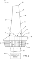
- the blade 15 comprises a root 17, an airfoil 18 and a platform 20.
- the root 17 is configured to be coupled to a supporting disc (not illustrated in the accompanying figures) of the gas turbine 5.
- the disc has a plurality of axial seats, which are circumferentially spaced and engaged by respective roots 17 of the rotating blades 15.
- the airfoil 18 extends from the root 17 and is provided with base 21 coupled to the root 17 and a tip 22 which, in use, is radially opposite to the base 21.
- the airfoil 18 is completely housed in the expansion channel 12 and defines the aerodynamic profile of the rotating blade 15.
- the airfoil 18 has a concave pressure side 24 (better visible in figures 3 and 4 ) and a convex suction side 25, which, in use, extend axially between a leading edge 27 and a trailing edge 28 and radially between the base 21 and the tip 22.
- the leading edge 27 is arranged upstream of the trailing edge 28 along the direction D of the hot working fluid in the expansion channel 12.
- the platform 20 is arranged between the root 17 and the airfoil 18.
- Blade 15 is provided with a cooling arrangement 29.
- the cooling arrangement 29 comprise a plurality of feeding channels 30 made in the root 17 and a plurality of cooling paths 31 (not illustrated in figure 2 and better visible in figures 3 and 4 ) made in the airfoil 18.
- the feeding channels 30 are supplied with a cooling fluid coming from a cooling fluid source 32.
- the cooling fluid source 32 is a portion of the compressor 3.
- a suction line 33 dedicated to the suction of cooling air from the compressor 3 and connected to the gas turbine 5 is shown.
- each feeding channel 30 is coupled to a respective cooling path 31.
- each feeding channels can be coupled to more than one cooling path.
- the feeding channels 30 are four and the cooling paths 31 are four.
- the cooling arrangement 29 comprises a suction side cooling path 31a mainly dedicated to the cooling of the suction side 25, a pressure side cooling path 31b mainly dedicated to the cooling of the pressure side 24, a leading edge cooling path 31c mainly dedicated to the cooling of the leading edge 27 and a trailing edge cooling path 31d mainly dedicated to the cooling of the trailing edge 28.
- a dashed line is used to schematically indicate the cooling path 31a
- a dashed-dotted line is used to schematically indicate the pressure side cooling path 31b
- a dotted line is used to schematically indicate the leading edge cooling path 31c
- a solid line is used to schematically indicate the trailing edge cooling path 31d.
- the airfoil 18 comprises an outer wall 35 and an inner wall 36.
- the outer wall 35 defines at least in part the aerodynamic profile of the blade 15 and has an external face 37 which, in use, is arranged in contact with the hot gas working fluid flowing in the expansion channel 12.
- the inner wall 36 is enclosed by the outer wall 35 and may have cooling and structural functions.
- the inner wall 36 defines an inner central cooling chamber 38, through which, in use, the cooling fluid coming from a respective feeding channel 30 flows as will be detailed in the following.
- the suction side cooling path 31a is defined between the inner wall 36 and the outer wall 35 and extends at least partially along the suction side 25.
- the suction side cooling path 31a comprises at least one inlet 40 (better visible in figure 2 ) and at least one discharge arrangement 41.
- the inlet 40 being arranged closer to the trailing edge 28 than the discharge arrangement 41.
- the suction side cooling path 31a comprises one inlet 40, which is defined by an aperture located at the base 21 of the airfoil 18 and in fluidic communication with the respective feeding channel 30 of the root 17.
- the suction side cooling path 31a comprises one discharge arrangement 41 which will be described in detail later.
- the suction side cooling path 31a comprises a plurality of suction side cooling chambers 42 which are in fluidic communication and arranged side by side between the inner wall 36 and the outer wall 35 along the suction side 25.
- Each of the suction side cooling chambers 42 extends substantially along a direction going from the base 21 toward the tip 22.
- the plurality of suction side cooling chambers 42 comprises a suction side inlet chamber 42a, which is the suction side cooling chamber 42 closest to the trailing edge 28, and a suction side discharge chamber 42b, which is the suction side cooling chamber 42 closest to the leading edge 27.
- the suction side inlet chamber 42a comprises the inlet 40 and the suction side discharge chamber 42b comprises the discharge arrangement 41.
- the suction side cooling path 31a comprises three suction side cooling chambers 42. In other words, between the suction side inlet chamber 42a and the suction side discharge chamber 42b only one suction side intermediate chamber 42c is arranged.
- the cooling fluid coming from the respective feeding channel 30 of the root 17 flows along the suction side inlet chamber 41a, along the suction side intermediate chamber 42c along the suction side discharge chamber 42b and exits through the discharge arrangement 41 of the suction side discharge chamber 42b.
- the flow of the cooling fluid along the suction side cooling path 31a is a counter-current flow with respect to the flow of the hot gas working fluid in the expansion channel 12 having direction D.
- the pressure side cooling path 31b is defined between the inner wall 36 and the outer wall 35 and extends at least partially along the pressure side 24.
- the pressure side cooling path 31b comprises at least one inlet 44 (better visible in figure 2 ) and at least one discharge arrangement 45.
- the discharge arrangement 45 being arranged closer to the trailing edge 28 than the inlet 44.
- the pressure side cooling path 31b comprises one inlet 44, which is defined by an aperture located at the base 21 of the airfoil 18 and in fluidic communication with the respective feeding channel 30 of the root 17.
- the pressure side cooling path 31b comprises two discharge arrangements 45, which will be described in detail later.
- the pressure side cooling path 31b comprises a plurality of pressure side cooling chambers 47 which are in fluidic communication and arranged side by side between the inner wall 36 and the outer wall 35 along the pressure side 24.
- Each of the pressure side cooling chambers 47 extends substantially along a direction going from the base 21 toward the tip 22.
- the plurality of pressure side cooling chambers 47 comprises a pressure side inlet chamber 47a, which is the pressure side cooling chamber 47 closest to the leading edge 27, and at least one pressure side discharge chamber 47b, which is the pressure side cooling chamber 47 closest to the trailing edge 28.
- the pressure side inlet chamber 47a comprises the inlet 44 and the pressure side discharge chamber 47b comprises at least one discharge arrangement 45.
- the pressure side cooling path 31b comprises three pressure side cooling chambers 47: one pressure side inlet chamber 47a and two subsequent discharge chambers 47b, each of which is provided with at least one discharge arrangement 45.
- the cooling fluid coming from the respective feeding channel 30 of the root 17 flows along the pressure side inlet chamber 47a, along the pressure side discharge chamber 47b adjacent to the pressure side inlet chamber 47a and along the pressure side discharge chamber 47b closest to the trailing edge 28 and exits through the two discharge arrangements 45 of the pressure side discharge chambers 47b.
- the flow of the cooling fluid along the pressure side cooling path 31b is a co-current flow with respect to the flow of the hot gas working fluid in the expansion channel 12 having direction D.
- the leading edge cooling path 31c is defined by the inner central cooling chamber 38 and by a leading edge cooling chamber 49 arranged between the inner wall 36 and the outer wall 35 at the leading edge 27.
- the inner central cooling chamber 38 being in fluidic communication with the leading edge cooling chamber 49 by at least one connecting aperture 50.
- the inner central cooling chamber 38 and the leading edge cooling chamber 49 extend substantially along a direction going from the base 21 toward the tip 22.
- the leading edge cooling path 31c comprising at least one inlet 51 (better visible in figure 2 ) and at least one discharge arrangement 53.
- the discharge arrangement 53 being arranged closer to the leading edge 27 than the inlet 51.
- the leading edge cooling path 31c comprises one inlet 51, which is defined by an aperture located at the base 21 of the airfoil 18 and in fluidic communication with the respective feeding channel 30 of the root 17.
- the leading edge cooling path 31c comprises a plurality of discharge arrangements 53, which will be described in detail later.
- the discharge arrangements 53 are at least three: at least one discharge arrangement 53 directed toward the leading edge 27, at least one discharge arrangement 53 directed toward the suction side 25 and at least one discharge arrangement 53 directed toward the pressure side 24.
- leading edge cooling chamber 49 comprises the discharge arrangements 53, while the inner central cooling chamber 38 comprises the inlet 51.
- the cooling fluid coming from the respective feeding channel 30 of the root 17 flows along the inner central cooling chamber 38, through the connecting aperture 50, along leading edge cooling chamber 49 and exits through the discharge arrangements 53 of the leading edge cooling chamber 49.
- the flow of the cooling fluid along the leading edge cooling path 31c is a co-current flow with respect to the flow of the hot gas working fluid in the expansion channel 12 having direction D.
- the trailing edge cooling path 31d is defined by a trailing edge cooling chamber 55 arranged between the inlet 40 of suction side cooling path 31a and the trailing edge 28.
- the trailing edge cooling chamber 55 extends substantially along a direction going from the base 21 toward the tip 22.
- the trailing edge cooling path 31d comprises at least one inlet 57 (better visible in figure 2 ) and at least one discharge arrangement 58.
- the discharge arrangement 58 being arranged on the pressure side 24 and configured to direct the flow toward the trailing edge 28.
- the trailing edge cooling path 31d comprises one inlet 57, which is defined by an aperture located at the base 21 of the airfoil 18 and in fluidic communication with the respective feeding channel 30 of the root 17.
- trailing edge cooling path 31d comprises one discharge arrangement 58, which will be described in detail later.
- the trailing edge cooling chamber 55 comprises the discharge arrangements 58 and the inlet 57.
- the cooling fluid coming from the respective feeding channel 30 of the root 17 flows along the trailing edge cooling chamber 55 and exits through the discharge arrangement 58 toward the trailing edge 28.
- suction side cooling chambers 42, the pressure side cooling chambers 47, the leading edge cooling chamber 49 and the trailing edge cooling chamber 55 can be optionally provided with at least one turbulator in order to improve the cooling effect.
- suction side cooling chambers 42, the pressure side cooling chambers 47 and the trailing edge cooling chamber 55 may comprise turbulators defined by ribs which project from at least one internal face of the respective chamber and are angled with respect to the direction of the cooling fluid inside the chamber.
- turbulators project from three adjacent internal faces of the respective chamber.
- the leading edge cooling chamber 49 may comprise a plurality of turbulators defined by ribs projecting from at least one internal face of the leading edge cooling chamber 49. Said ribs have a trapezoidal-shaped section. Preferably said turbulators are arranged staggered with respect to the inlet holes of the cooling arrangements 53 at least on the two internal faces of the leading edge cooling chamber 49 which are respectively closest to the pressure side 24 and to the suction side 25.
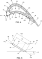
- the discharging arrangement 41 of the suction side cooling path 31a, the discharge arrangements 45 of the pressure side cooling path 31b, the discharge arrangements 53 of the leading edge cooling path 31c and the discharge arrangement 58 of the trailing edge cooling path 31d have all the structure illustrated in figures 5 and 6 .
- At least one of the discharge arrangement 41 45 53 58 have the structure illustrated in figures 5 and 6 .
- Discharge arrangement 45 extends through the outer wall 35 from the respective internal face of the pressure side discharge cooling chamber 47b to the external face 37 of the outer wall 35.
- the discharge arrangement 45 comprises a plurality of inlet holes 60, an outlet common slot 61 and a plurality of connecting channels 63, each of which is configured to connect a respective hole 60 with the outlet common slot 61.
- the inlet holes 60 are identical to each other.
- the connecting channels 63 are identical to each other.
- the connecting channels 63 are diverging toward the outlet common slot 61.
- the connecting channels 63 have a passage area which gradually increases toward the outlet common slot 61.
- the increase of the passage area starts from an inlet section 65 of the connecting channels 63 and ends at an outlet section 66 of the connecting channels 63.
- the inlet section 65 of each connecting channel 63 being in contact with the respective inlet hole 60 and the outlet section 66 of each connecting channel 63 being in contact with the outlet common slot 61.
- the passage area of the inlet holes 60 is constant.
- the passage area of the inlet hole 60 is smaller than the passage area of the inlet section 65 of the respective connecting channels 63.
- the passage area of the inlet section 65 of the respective connecting channels 63 is 10-20% greater than the passage area of the inlet hole 60.
- the area ratio between inlet section 65 and outlet section 66 of the connecting channels 63 is comprised between 3,5 to 5.
- the inlet holes 60 are substantially aligned along a direction F on the respective internal face of the pressure side discharge cooling chamber 47b.
- the inlet holes 60 are arranged equally spaced from each other.
- the outlet common slot 61 is substantially aligned along a direction parallel to direction F.
- Direction F is substantially a straight line extending from the base 21 to tip 22 of the airfoil 18.
- the discharge arrangement 45 extends along a main axis G which is inclined with respect to the external face 37 of the outer wall with an angle ⁇ .
- the inlet holes 60 and the connecting channels 63 and the outlet common slot 61 extends along said main axis G as shown in the cross section of figure 5 .
- the depth DH of the inlet holes 60 is 10-20% of the total depth Dtot of the outer wall 35; wherein both depth DH and depth Dtot are measured along the main axis G.
- the depth DC of the connecting channels 63 is 50%-70% of the total depth Dtot of the outer wall 35; wherein both depth DC and depth Dtot are measured along the main axis G.
- Depth DS of the outlet common slot 61 is 20-30% of the total depth Dtot of the outer wall 35; wherein both depth DS and depth Dtot are measured along the main axis G.
- the angle ⁇ of inclination and the total depth of the outer wall 35 measured along the main axis G can be different for each one of the discharge arrangements 41 45 53 58.
- the angle ⁇ of discharge arrangement 58 is equal or greater than the angle ⁇ of discharge arrangement 45.
- the cooling fluid coming from the respective pressure side discharge cooling chamber 47b is divided by the plurality of inlet holes 60, flows into the respective connecting channels 63 and joins at the outlet common slot 61.
- a single wide and homogenous flow of cooling fluid exits from the outlet common slot 61 as indicated also by the arrow in figure 6 .
- outlet common slot 61 improves the film cooling efficiency as the external face 37 of the outer wall 35 is lapped by a cooling flow which is wide and homogeneous.
- FIG 7 a further embodiment of the discharge arrangement 145 is illustrated.
- the same reference numbers used for the cooling arrangement 45 of figures 5 and 6 are used also in figure 7 for indicating similar or identical parts.
- the discharge arrangement 145 comprises at least two discharge groups 146
- the discharge arrangement 145 comprises three discharge groups 146.
- Each discharge group 146 comprises a plurality of inlet holes 160, an outlet common slot 161 and a plurality of connecting channels 163, each of which is configured to connect a respective hole 160 with the outlet common slot 161.
- each connecting channel 163 have an inlet section 165 and an outlet section 166; the inlet section 165 of each connecting channel 163 being in contact with the respective inlet hole 160 and the outlet section 166 of each connecting channel 163 being in contact with the outlet common slot 161.
- the passage area of each inlet hole 160 is preferably smaller than the passage area of the inlet section 165 of the respective connecting channels 163 analogously to the embodiment illustrated in figure 6 .
- each discharge group 146 comprises a three inlet holes 160, an outlet common slot 161 and three connecting channels 163, each of which is configured to connect a respective hole 160 with the outlet common slot 161.
- the inlet holes 160 of each group 146 are equally spaced one from the other.
- the discharge groups 146 are spaced one from the other. Preferably the discharge groups 146 are equally spaced one from the other.
- cooling fluid coming from the respective pressure side discharge cooling chamber 47b is divided by the plurality of inlet holes 160, flows into the respective connecting channels 163 and joins at the outlet common slots 161.
- three homogenous flows of cooling fluid exits from the outlet common slots 161 as indicated also by the arrows in figure 7 .
Landscapes
- Engineering & Computer Science (AREA)
- Mechanical Engineering (AREA)
- General Engineering & Computer Science (AREA)
- Turbine Rotor Nozzle Sealing (AREA)
Claims (9)
- Schaufel für eine Gasturbine (5), umfassend:ein Schaufelprofil (18), das eine Vorderkante (27), eine Hinterkante (28), eine Druckseite (24) und eine Saugseite (25) aufweist;wobei das Schaufelprofil (18) eine Außenwand (35) und eine Innenwand (36), die im Wesentlichen von der Außenwand (35) umschlossen wird, umfasst;und eine Kühlanordnung (29), die einen Saugseiten-Kühlpfad (31a) umfasst, der mindestens teilweise entlang der Saugseite (25) zwischen der Außenwand (35) und der Innenwand (36) definiert ist;wobei der Saugseiten-Kühlpfad (31a) mindestens einen Saugseiten-Einlass (40) und mindestens eine Saugseiten-Auslassanordnung (41) aufweist, die sich durch die Außenwand (35) erstreckt; wobei der Saugseiten-Einlass (40) näher an der Hinterkante (28) als die Saugseiten-Auslassanordnung (41) angeordnet ist;wobei die Kühlanordnung (29) einen Hinterkanten-Kühlpfad (31d) umfasst, der durch eine Hinterkanten-Kühlkammer (55) definiert ist, die zwischen dem Saugseiten-Einlass (40) des Saugseiten-Kühlpfads (31a) und der Hinterkante (28) angeordnet ist; wobei der Hinterkanten-Kühlpfad (31d) mindestens einen Hinterkanten-Einlass (57) und mindestens eine Hinterkanten-Auslassanordnung (58) umfasst; wobei die Hinterkanten-Auslassanordnung (58) auf der Druckseite (24) angeordnet und dazu konfiguriert ist, die Strömung zur Hinterkante (28) hin zu leiten;dadurch gekennzeichnet, dass die Saugseiten-Auslassanordnung (41) eine Mehrzahl von Einlassöffnungen (60; 160), mindestens einen gemeinsamen Auslassschlitz (61; 161) und eine Mehrzahl von Verbindungskanälen (63; 163) umfasst, von denen jeder dazu konfiguriert ist, eine Öffnung (60; 160) jeweils mit dem gemeinsamen Auslassschlitz (61; 161) zu verbinden.
- Schaufel gemäß Anspruch 1, wobei der Saugseiten-Kühlpfad (31a) eine Mehrzahl von Saugseiten-Kühlkammern (42) in Fluidkommunikation und nebeneinander angeordnet umfasst; wobei die Mehrzahl von Saugseiten-Kühlkammern (42) eine Saugseiten-Einlasskammer (42a), die die Saugseiten-Kühlkammer ist, die der Hinterkante (28) am nächsten liegt, und eine Saugseiten-Auslasskammer (42b) umfasst, die die Saugseiten-Kühlkammer ist, die der Vorderkante (27) am nächsten liegt; wobei die Saugseiten-Einlasskammer (42a) den Saugseiten-Einlass (40) umfasst und die Saugseiten-Auslasskammer (42b) die Saugseiten-Auslassanordnung (41) umfasst.
- Schaufel gemäß Anspruch 2, wobei das Schaufelprofil (18) eine Basis (21) und eine Spitze (22) hat; wobei sich die Mehrzahl von Saugseiten-Kühlkammern (42) im Wesentlichen entlang einer Richtung erstreckt, die von der Basis (21) zur Spitze (22) hin geht.
- Schaufel gemäß Anspruch 2 oder 3, wobei mindestens eine Saugseiten-Kühlkammer (42) mit mindestens einem Turbulator ausgestattet ist.
- Schaufel gemäß einem der vorhergehenden Ansprüche, wobei die Kühlanordnung (29) einen Druckseiten-Kühlpfad (31b) umfasst, der zwischen der Innenwand (36) und der Außenwand (35) definiert ist und sich mindestens teilweise entlang der Druckseite (24) erstreckt; wobei der Druckseiten-Kühlpfad (31b) mindestens einen Druckseiten-Einlass (44) und mindestens eine Druckseiten-Auslassanordnung (45) umfasst; wobei die Druckseiten-Auslassanordnung (45) näher an der Hinterkante (28) als der Druckseiten-Einlass (44) angeordnet ist.
- Schaufel gemäß Anspruch 5, wobei der Druckseiten-Kühlpfad (31b) eine Mehrzahl von Druckseiten-Kühlkammern (47) umfasst, die in Fluidkommunikation und nebeneinander zwischen der Innenwand (36) und der Außenwand (35) entlang der Druckseite (24) angeordnet sind; wobei die Mehrzahl von Druckseiten-Kühlkammern (47) eine Druckseiten-Einlasskammer (47a), die die Druckseiten-Kühlkammer (47) ist, die der Vorderkante (27) am nächsten liegt, und mindestens eine Druckseiten-Auslasskammer (47b) umfasst, die die Druckseiten-Kühlkammer (47) ist, die der Hinterkante (28) am nächsten liegt; wobei die Druckseiten-Einlasskammer (47a) den Druckseiten-Einlass (44) umfasst und die Druckseiten-Auslasskammer (47b) mindestens eine Druckseiten-Auslassanordnung (45) umfasst.
- Schaufel gemäß einem der vorhergehenden Ansprüche, wobei die Kühlanordnung (29) einen Vorderkanten-Kühlpfad (31c) umfasst, der eine innere mittige Kühlkammer (38) umfasst, die durch die Innenwand (36) und eine Vorderkanten-Kühlkammer (49) definiert ist, die zwischen der Innenwand (36) und der Außenwand (35) an der Vorderkante (27) angeordnet ist; wobei die innere mittige Kühlkammer (38) in Fluidkommunikation mit der Vorderkanten-Kühlkammer (49) ist; wobei der Vorderkanten-Kühlpfad (31c) mindestens einen Vorderkanten-Einlass (51) und mindestens eine Vorderkanten-Auslassanordnung (53) umfasst; wobei die Vorderkanten-Auslassanordnung (53) näher an der Vorderkante (27) als der Vorderkanten-Einlass (51) angeordnet ist.
- Anlage zur Produktion elektrischen Stroms, umfassend mindestens eine Gasturbine (5), die sich entlang einer Längsachse (A) erstreckt und mindestens eine Reihe von Schaufeln (15) umfasst, die in Umfangsrichtung beabstandet sind und sich von einer jeweiligen Trägerscheibe der Gasturbine (5) radial nach außen erstrecken; wobei mindestens eine der Schaufeln (15) der Reihe der Art ist, die in einem der vorhergehenden Ansprüche beansprucht ist.
- Anlage gemäß Anspruch 8, umfassend mindestens einen Kompressor (3), der mit der Gasturbine (5) über eine Saugleitung (33) verbunden ist, die dazu konfiguriert ist, Kühlluft von dem Kompressor (3) zu beziehen und sie der Kühlanordnung (29) der mindestens einen Schaufel (15) zuzuführen.
Priority Applications (3)
| Application Number | Priority Date | Filing Date | Title |
|---|---|---|---|
| EP17174866.8A EP3412867B8 (de) | 2017-06-07 | 2017-06-07 | Gekühlte gasturbinenschaufel |
| CN202610946180.5A CN122504510A (zh) | 2017-06-07 | 2018-06-07 | 用于燃气涡轮的叶片和包括所述叶片的电力生成设备 |
| CN201810580811.1A CN108999646A (zh) | 2017-06-07 | 2018-06-07 | 用于燃气涡轮的叶片和包括所述叶片的电力生成设备 |
Applications Claiming Priority (1)
| Application Number | Priority Date | Filing Date | Title |
|---|---|---|---|
| EP17174866.8A EP3412867B8 (de) | 2017-06-07 | 2017-06-07 | Gekühlte gasturbinenschaufel |
Publications (3)
| Publication Number | Publication Date |
|---|---|
| EP3412867A1 EP3412867A1 (de) | 2018-12-12 |
| EP3412867B1 true EP3412867B1 (de) | 2024-01-03 |
| EP3412867B8 EP3412867B8 (de) | 2024-02-14 |
Family
ID=59030843
Family Applications (1)
| Application Number | Title | Priority Date | Filing Date |
|---|---|---|---|
| EP17174866.8A Active EP3412867B8 (de) | 2017-06-07 | 2017-06-07 | Gekühlte gasturbinenschaufel |
Country Status (2)
| Country | Link |
|---|---|
| EP (1) | EP3412867B8 (de) |
| CN (2) | CN122504510A (de) |
Families Citing this family (1)
| Publication number | Priority date | Publication date | Assignee | Title |
|---|---|---|---|---|
| US10787932B2 (en) * | 2018-07-13 | 2020-09-29 | Honeywell International Inc. | Turbine blade with dust tolerant cooling system |
Citations (2)
| Publication number | Priority date | Publication date | Assignee | Title |
|---|---|---|---|---|
| US4303374A (en) * | 1978-12-15 | 1981-12-01 | General Electric Company | Film cooled airfoil body |
| US7563073B1 (en) * | 2006-10-10 | 2009-07-21 | Florida Turbine Technologies, Inc. | Turbine blade with film cooling slot |
Family Cites Families (9)
| Publication number | Priority date | Publication date | Assignee | Title |
|---|---|---|---|---|
| JPS55114806A (en) * | 1979-02-27 | 1980-09-04 | Hitachi Ltd | Gas turbine blade |
| FR2829174B1 (fr) * | 2001-08-28 | 2006-01-20 | Snecma Moteurs | Perfectionnement apportes aux circuits de refroidissement pour aube de turbine a gaz |
| US6981846B2 (en) * | 2003-03-12 | 2006-01-03 | Florida Turbine Technologies, Inc. | Vortex cooling of turbine blades |
| US7862299B1 (en) * | 2007-03-21 | 2011-01-04 | Florida Turbine Technologies, Inc. | Two piece hollow turbine blade with serpentine cooling circuits |
| EP2107215B1 (de) | 2008-03-31 | 2013-10-23 | Alstom Technology Ltd | Gasturbinenschaufel |
| US8066483B1 (en) * | 2008-12-18 | 2011-11-29 | Florida Turbine Technologies, Inc. | Turbine airfoil with non-parallel pin fins |
| US8366392B1 (en) * | 2009-05-06 | 2013-02-05 | Florida Turbine Technologies, Inc. | Composite air cooled turbine rotor blade |
| US8585365B1 (en) * | 2010-04-13 | 2013-11-19 | Florida Turbine Technologies, Inc. | Turbine blade with triple pass serpentine cooling |
| CN106593543B (zh) * | 2016-11-28 | 2018-04-17 | 西北工业大学 | 一种用于涡轮叶片的拱型凹槽气膜冷却结构 |
-
2017
- 2017-06-07 EP EP17174866.8A patent/EP3412867B8/de active Active
-
2018
- 2018-06-07 CN CN202610946180.5A patent/CN122504510A/zh active Pending
- 2018-06-07 CN CN201810580811.1A patent/CN108999646A/zh active Pending
Patent Citations (2)
| Publication number | Priority date | Publication date | Assignee | Title |
|---|---|---|---|---|
| US4303374A (en) * | 1978-12-15 | 1981-12-01 | General Electric Company | Film cooled airfoil body |
| US7563073B1 (en) * | 2006-10-10 | 2009-07-21 | Florida Turbine Technologies, Inc. | Turbine blade with film cooling slot |
Also Published As
| Publication number | Publication date |
|---|---|
| CN122504510A (zh) | 2026-08-04 |
| EP3412867A1 (de) | 2018-12-12 |
| CN108999646A (zh) | 2018-12-14 |
| EP3412867B8 (de) | 2024-02-14 |
Similar Documents
| Publication | Publication Date | Title |
|---|---|---|
| US8182223B2 (en) | Turbine blade cooling | |
| US8858159B2 (en) | Gas turbine engine component having wavy cooling channels with pedestals | |
| US8011881B1 (en) | Turbine vane with serpentine cooling | |
| CA2668605C (en) | Crossflow turbine airfoil | |
| CN1987055B (zh) | 平衡冷却的涡轮机喷嘴 | |
| JP5503140B2 (ja) | 発散型タービンノズル | |
| US9004866B2 (en) | Turbine blade incorporating trailing edge cooling design | |
| EP3155233B1 (de) | Gasturbinenmotor mit rotorzentrierungs- und -kühlsystem in einem abgasdiffusor | |
| EP1022435B1 (de) | Interner Kühlkreislauf für eine Gasturbinenschaufel | |
| JP6650687B2 (ja) | ロータブレード冷却 | |
| US9810070B2 (en) | Turbine rotor blade for a turbine section of a gas turbine | |
| JP5948436B2 (ja) | 翼冷却回路 | |
| CN114961878A (zh) | 改进的涡轮叶片冷却系统 | |
| US20150184538A1 (en) | Interior cooling circuits in turbine blades | |
| KR20160037093A (ko) | 가스 터빈의 터빈 블레이드를 위한 냉각 기구 | |
| CN106150561B (zh) | 涡轮翼型件扰流器布置 | |
| CN106988791A (zh) | 具有内带和外带冷却的涡轮喷嘴 | |
| CN105937410A (zh) | 涡轮转子叶片 | |
| US9759071B2 (en) | Structural configurations and cooling circuits in turbine blades | |
| US8079811B1 (en) | Turbine blade with multi-impingement cooled squealer tip | |
| RU2514818C1 (ru) | Охлаждаемая турбина | |
| EP3412866B1 (de) | Gekühlte gasturbinenschaufel | |
| JP6598999B2 (ja) | 軸方向隔壁を特徴とする後縁冷却を備えるタービン翼 | |
| US10774664B2 (en) | Plenum for cooling turbine flowpath components and blades | |
| EP3412867A1 (de) | Gekühlte gasturbinenschaufel |
Legal Events
| Date | Code | Title | Description |
|---|---|---|---|
| PUAI | Public reference made under article 153(3) epc to a published international application that has entered the european phase |
Free format text: ORIGINAL CODE: 0009012 |
|
| STAA | Information on the status of an ep patent application or granted ep patent |
Free format text: STATUS: THE APPLICATION HAS BEEN PUBLISHED |
|
| AK | Designated contracting states |
Kind code of ref document: A1 Designated state(s): AL AT BE BG CH CY CZ DE DK EE ES FI FR GB GR HR HU IE IS IT LI LT LU LV MC MK MT NL NO PL PT RO RS SE SI SK SM TR |
|
| AX | Request for extension of the european patent |
Extension state: BA ME |
|
| STAA | Information on the status of an ep patent application or granted ep patent |
Free format text: STATUS: REQUEST FOR EXAMINATION WAS MADE |
|
| 17P | Request for examination filed |
Effective date: 20190611 |
|
| RBV | Designated contracting states (corrected) |
Designated state(s): AL AT BE BG CH CY CZ DE DK EE ES FI FR GB GR HR HU IE IS IT LI LT LU LV MC MK MT NL NO PL PT RO RS SE SI SK SM TR |
|
| STAA | Information on the status of an ep patent application or granted ep patent |
Free format text: STATUS: EXAMINATION IS IN PROGRESS |
|
| 17Q | First examination report despatched |
Effective date: 20200821 |
|
| GRAP | Despatch of communication of intention to grant a patent |
Free format text: ORIGINAL CODE: EPIDOSNIGR1 |
|
| STAA | Information on the status of an ep patent application or granted ep patent |
Free format text: STATUS: GRANT OF PATENT IS INTENDED |
|
| INTG | Intention to grant announced |
Effective date: 20230725 |
|
| GRAS | Grant fee paid |
Free format text: ORIGINAL CODE: EPIDOSNIGR3 |
|
| GRAA | (expected) grant |
Free format text: ORIGINAL CODE: 0009210 |
|
| STAA | Information on the status of an ep patent application or granted ep patent |
Free format text: STATUS: THE PATENT HAS BEEN GRANTED |
|
| AK | Designated contracting states |
Kind code of ref document: B1 Designated state(s): AL AT BE BG CH CY CZ DE DK EE ES FI FR GB GR HR HU IE IS IT LI LT LU LV MC MK MT NL NO PL PT RO RS SE SI SK SM TR |
|
| REG | Reference to a national code |
Ref country code: GB Ref legal event code: FG4D |
|
| REG | Reference to a national code |
Ref country code: CH Ref legal event code: EP |
|
| RAP4 | Party data changed (patent owner data changed or rights of a patent transferred) |
Owner name: ANSALDO ENERGIA SWITZERLAND AG |
|
| REG | Reference to a national code |
Ref country code: DE Ref legal event code: R096 Ref document number: 602017078061 Country of ref document: DE |
|
| REG | Reference to a national code |
Ref country code: IE Ref legal event code: FG4D Ref country code: CH Ref legal event code: PK Free format text: BERICHTIGUNG B8 |
|
| REG | Reference to a national code |
Ref country code: LT Ref legal event code: MG9D |
|
| PG25 | Lapsed in a contracting state [announced via postgrant information from national office to epo] |
Ref country code: ES Free format text: LAPSE BECAUSE OF FAILURE TO SUBMIT A TRANSLATION OF THE DESCRIPTION OR TO PAY THE FEE WITHIN THE PRESCRIBED TIME-LIMIT Effective date: 20240103 |
|
| PG25 | Lapsed in a contracting state [announced via postgrant information from national office to epo] |
Ref country code: ES Free format text: LAPSE BECAUSE OF FAILURE TO SUBMIT A TRANSLATION OF THE DESCRIPTION OR TO PAY THE FEE WITHIN THE PRESCRIBED TIME-LIMIT Effective date: 20240103 |
|
| REG | Reference to a national code |
Ref country code: NL Ref legal event code: MP Effective date: 20240103 |
|
| P01 | Opt-out of the competence of the unified patent court (upc) registered |
Effective date: 20240430 |
|
| REG | Reference to a national code |
Ref country code: AT Ref legal event code: MK05 Ref document number: 1646989 Country of ref document: AT Kind code of ref document: T Effective date: 20240103 |
|
| PG25 | Lapsed in a contracting state [announced via postgrant information from national office to epo] |
Ref country code: NL Free format text: LAPSE BECAUSE OF FAILURE TO SUBMIT A TRANSLATION OF THE DESCRIPTION OR TO PAY THE FEE WITHIN THE PRESCRIBED TIME-LIMIT Effective date: 20240103 |
|
| PG25 | Lapsed in a contracting state [announced via postgrant information from national office to epo] |
Ref country code: NL Free format text: LAPSE BECAUSE OF FAILURE TO SUBMIT A TRANSLATION OF THE DESCRIPTION OR TO PAY THE FEE WITHIN THE PRESCRIBED TIME-LIMIT Effective date: 20240103 |
|
| PG25 | Lapsed in a contracting state [announced via postgrant information from national office to epo] |
Ref country code: IS Free format text: LAPSE BECAUSE OF FAILURE TO SUBMIT A TRANSLATION OF THE DESCRIPTION OR TO PAY THE FEE WITHIN THE PRESCRIBED TIME-LIMIT Effective date: 20240503 |
|
| PG25 | Lapsed in a contracting state [announced via postgrant information from national office to epo] |
Ref country code: LT Free format text: LAPSE BECAUSE OF FAILURE TO SUBMIT A TRANSLATION OF THE DESCRIPTION OR TO PAY THE FEE WITHIN THE PRESCRIBED TIME-LIMIT Effective date: 20240103 |
|
| PG25 | Lapsed in a contracting state [announced via postgrant information from national office to epo] |
Ref country code: GR Free format text: LAPSE BECAUSE OF FAILURE TO SUBMIT A TRANSLATION OF THE DESCRIPTION OR TO PAY THE FEE WITHIN THE PRESCRIBED TIME-LIMIT Effective date: 20240404 |
|
| PG25 | Lapsed in a contracting state [announced via postgrant information from national office to epo] |
Ref country code: RS Free format text: LAPSE BECAUSE OF FAILURE TO SUBMIT A TRANSLATION OF THE DESCRIPTION OR TO PAY THE FEE WITHIN THE PRESCRIBED TIME-LIMIT Effective date: 20240403 Ref country code: HR Free format text: LAPSE BECAUSE OF FAILURE TO SUBMIT A TRANSLATION OF THE DESCRIPTION OR TO PAY THE FEE WITHIN THE PRESCRIBED TIME-LIMIT Effective date: 20240103 |
|
| PG25 | Lapsed in a contracting state [announced via postgrant information from national office to epo] |
Ref country code: AT Free format text: LAPSE BECAUSE OF FAILURE TO SUBMIT A TRANSLATION OF THE DESCRIPTION OR TO PAY THE FEE WITHIN THE PRESCRIBED TIME-LIMIT Effective date: 20240103 |
|
| PG25 | Lapsed in a contracting state [announced via postgrant information from national office to epo] |
Ref country code: RS Free format text: LAPSE BECAUSE OF FAILURE TO SUBMIT A TRANSLATION OF THE DESCRIPTION OR TO PAY THE FEE WITHIN THE PRESCRIBED TIME-LIMIT Effective date: 20240403 Ref country code: NO Free format text: LAPSE BECAUSE OF FAILURE TO SUBMIT A TRANSLATION OF THE DESCRIPTION OR TO PAY THE FEE WITHIN THE PRESCRIBED TIME-LIMIT Effective date: 20240403 Ref country code: LT Free format text: LAPSE BECAUSE OF FAILURE TO SUBMIT A TRANSLATION OF THE DESCRIPTION OR TO PAY THE FEE WITHIN THE PRESCRIBED TIME-LIMIT Effective date: 20240103 Ref country code: IS Free format text: LAPSE BECAUSE OF FAILURE TO SUBMIT A TRANSLATION OF THE DESCRIPTION OR TO PAY THE FEE WITHIN THE PRESCRIBED TIME-LIMIT Effective date: 20240503 Ref country code: HR Free format text: LAPSE BECAUSE OF FAILURE TO SUBMIT A TRANSLATION OF THE DESCRIPTION OR TO PAY THE FEE WITHIN THE PRESCRIBED TIME-LIMIT Effective date: 20240103 Ref country code: GR Free format text: LAPSE BECAUSE OF FAILURE TO SUBMIT A TRANSLATION OF THE DESCRIPTION OR TO PAY THE FEE WITHIN THE PRESCRIBED TIME-LIMIT Effective date: 20240404 Ref country code: BG Free format text: LAPSE BECAUSE OF FAILURE TO SUBMIT A TRANSLATION OF THE DESCRIPTION OR TO PAY THE FEE WITHIN THE PRESCRIBED TIME-LIMIT Effective date: 20240103 Ref country code: AT Free format text: LAPSE BECAUSE OF FAILURE TO SUBMIT A TRANSLATION OF THE DESCRIPTION OR TO PAY THE FEE WITHIN THE PRESCRIBED TIME-LIMIT Effective date: 20240103 |
|
| PG25 | Lapsed in a contracting state [announced via postgrant information from national office to epo] |
Ref country code: PL Free format text: LAPSE BECAUSE OF FAILURE TO SUBMIT A TRANSLATION OF THE DESCRIPTION OR TO PAY THE FEE WITHIN THE PRESCRIBED TIME-LIMIT Effective date: 20240103 Ref country code: PT Free format text: LAPSE BECAUSE OF FAILURE TO SUBMIT A TRANSLATION OF THE DESCRIPTION OR TO PAY THE FEE WITHIN THE PRESCRIBED TIME-LIMIT Effective date: 20240503 |
|
| PG25 | Lapsed in a contracting state [announced via postgrant information from national office to epo] |
Ref country code: SE Free format text: LAPSE BECAUSE OF FAILURE TO SUBMIT A TRANSLATION OF THE DESCRIPTION OR TO PAY THE FEE WITHIN THE PRESCRIBED TIME-LIMIT Effective date: 20240103 Ref country code: PT Free format text: LAPSE BECAUSE OF FAILURE TO SUBMIT A TRANSLATION OF THE DESCRIPTION OR TO PAY THE FEE WITHIN THE PRESCRIBED TIME-LIMIT Effective date: 20240503 Ref country code: PL Free format text: LAPSE BECAUSE OF FAILURE TO SUBMIT A TRANSLATION OF THE DESCRIPTION OR TO PAY THE FEE WITHIN THE PRESCRIBED TIME-LIMIT Effective date: 20240103 Ref country code: LV Free format text: LAPSE BECAUSE OF FAILURE TO SUBMIT A TRANSLATION OF THE DESCRIPTION OR TO PAY THE FEE WITHIN THE PRESCRIBED TIME-LIMIT Effective date: 20240103 |
|
| REG | Reference to a national code |
Ref country code: DE Ref legal event code: R097 Ref document number: 602017078061 Country of ref document: DE |
|
| PG25 | Lapsed in a contracting state [announced via postgrant information from national office to epo] |
Ref country code: DK Free format text: LAPSE BECAUSE OF FAILURE TO SUBMIT A TRANSLATION OF THE DESCRIPTION OR TO PAY THE FEE WITHIN THE PRESCRIBED TIME-LIMIT Effective date: 20240103 |
|
| PG25 | Lapsed in a contracting state [announced via postgrant information from national office to epo] |
Ref country code: SM Free format text: LAPSE BECAUSE OF FAILURE TO SUBMIT A TRANSLATION OF THE DESCRIPTION OR TO PAY THE FEE WITHIN THE PRESCRIBED TIME-LIMIT Effective date: 20240103 |
|
| PG25 | Lapsed in a contracting state [announced via postgrant information from national office to epo] |
Ref country code: EE Free format text: LAPSE BECAUSE OF FAILURE TO SUBMIT A TRANSLATION OF THE DESCRIPTION OR TO PAY THE FEE WITHIN THE PRESCRIBED TIME-LIMIT Effective date: 20240103 Ref country code: CZ Free format text: LAPSE BECAUSE OF FAILURE TO SUBMIT A TRANSLATION OF THE DESCRIPTION OR TO PAY THE FEE WITHIN THE PRESCRIBED TIME-LIMIT Effective date: 20240103 |
|
| PG25 | Lapsed in a contracting state [announced via postgrant information from national office to epo] |
Ref country code: SK Free format text: LAPSE BECAUSE OF FAILURE TO SUBMIT A TRANSLATION OF THE DESCRIPTION OR TO PAY THE FEE WITHIN THE PRESCRIBED TIME-LIMIT Effective date: 20240103 |
|
| PG25 | Lapsed in a contracting state [announced via postgrant information from national office to epo] |
Ref country code: SM Free format text: LAPSE BECAUSE OF FAILURE TO SUBMIT A TRANSLATION OF THE DESCRIPTION OR TO PAY THE FEE WITHIN THE PRESCRIBED TIME-LIMIT Effective date: 20240103 Ref country code: SK Free format text: LAPSE BECAUSE OF FAILURE TO SUBMIT A TRANSLATION OF THE DESCRIPTION OR TO PAY THE FEE WITHIN THE PRESCRIBED TIME-LIMIT Effective date: 20240103 Ref country code: RO Free format text: LAPSE BECAUSE OF FAILURE TO SUBMIT A TRANSLATION OF THE DESCRIPTION OR TO PAY THE FEE WITHIN THE PRESCRIBED TIME-LIMIT Effective date: 20240103 Ref country code: EE Free format text: LAPSE BECAUSE OF FAILURE TO SUBMIT A TRANSLATION OF THE DESCRIPTION OR TO PAY THE FEE WITHIN THE PRESCRIBED TIME-LIMIT Effective date: 20240103 Ref country code: DK Free format text: LAPSE BECAUSE OF FAILURE TO SUBMIT A TRANSLATION OF THE DESCRIPTION OR TO PAY THE FEE WITHIN THE PRESCRIBED TIME-LIMIT Effective date: 20240103 Ref country code: CZ Free format text: LAPSE BECAUSE OF FAILURE TO SUBMIT A TRANSLATION OF THE DESCRIPTION OR TO PAY THE FEE WITHIN THE PRESCRIBED TIME-LIMIT Effective date: 20240103 |
|
| PLBE | No opposition filed within time limit |
Free format text: ORIGINAL CODE: 0009261 |
|
| STAA | Information on the status of an ep patent application or granted ep patent |
Free format text: STATUS: NO OPPOSITION FILED WITHIN TIME LIMIT |
|
| 26N | No opposition filed |
Effective date: 20241007 |
|
| PG25 | Lapsed in a contracting state [announced via postgrant information from national office to epo] |
Ref country code: MC Free format text: LAPSE BECAUSE OF FAILURE TO SUBMIT A TRANSLATION OF THE DESCRIPTION OR TO PAY THE FEE WITHIN THE PRESCRIBED TIME-LIMIT Effective date: 20240103 |
|
| REG | Reference to a national code |
Ref country code: CH Ref legal event code: PL |
|
| PG25 | Lapsed in a contracting state [announced via postgrant information from national office to epo] |
Ref country code: LU Free format text: LAPSE BECAUSE OF NON-PAYMENT OF DUE FEES Effective date: 20240607 |
|
| GBPC | Gb: european patent ceased through non-payment of renewal fee |
Effective date: 20240607 |
|
| PG25 | Lapsed in a contracting state [announced via postgrant information from national office to epo] |
Ref country code: IE Free format text: LAPSE BECAUSE OF NON-PAYMENT OF DUE FEES Effective date: 20240607 |
|
| PG25 | Lapsed in a contracting state [announced via postgrant information from national office to epo] |
Ref country code: SI Free format text: LAPSE BECAUSE OF FAILURE TO SUBMIT A TRANSLATION OF THE DESCRIPTION OR TO PAY THE FEE WITHIN THE PRESCRIBED TIME-LIMIT Effective date: 20240103 Ref country code: BE Free format text: LAPSE BECAUSE OF NON-PAYMENT OF DUE FEES Effective date: 20240630 Ref country code: CH Free format text: LAPSE BECAUSE OF NON-PAYMENT OF DUE FEES Effective date: 20240630 |
|
| PG25 | Lapsed in a contracting state [announced via postgrant information from national office to epo] |
Ref country code: FR Free format text: LAPSE BECAUSE OF NON-PAYMENT OF DUE FEES Effective date: 20240630 |
|
| PG25 | Lapsed in a contracting state [announced via postgrant information from national office to epo] |
Ref country code: GB Free format text: LAPSE BECAUSE OF NON-PAYMENT OF DUE FEES Effective date: 20240607 |
|
| REG | Reference to a national code |
Ref country code: BE Ref legal event code: MM Effective date: 20240630 |
|
| PG25 | Lapsed in a contracting state [announced via postgrant information from national office to epo] |
Ref country code: FI Free format text: LAPSE BECAUSE OF FAILURE TO SUBMIT A TRANSLATION OF THE DESCRIPTION OR TO PAY THE FEE WITHIN THE PRESCRIBED TIME-LIMIT Effective date: 20240103 |
|
| PGFP | Annual fee paid to national office [announced via postgrant information from national office to epo] |
Ref country code: IT Payment date: 20250630 Year of fee payment: 9 |
|
| PG25 | Lapsed in a contracting state [announced via postgrant information from national office to epo] |
Ref country code: CY Free format text: LAPSE BECAUSE OF FAILURE TO SUBMIT A TRANSLATION OF THE DESCRIPTION OR TO PAY THE FEE WITHIN THE PRESCRIBED TIME-LIMIT; INVALID AB INITIO Effective date: 20170607 |
|
| PG25 | Lapsed in a contracting state [announced via postgrant information from national office to epo] |
Ref country code: HU Free format text: LAPSE BECAUSE OF FAILURE TO SUBMIT A TRANSLATION OF THE DESCRIPTION OR TO PAY THE FEE WITHIN THE PRESCRIBED TIME-LIMIT; INVALID AB INITIO Effective date: 20170607 |
|
| PG25 | Lapsed in a contracting state [announced via postgrant information from national office to epo] |
Ref country code: TR Free format text: LAPSE BECAUSE OF FAILURE TO SUBMIT A TRANSLATION OF THE DESCRIPTION OR TO PAY THE FEE WITHIN THE PRESCRIBED TIME-LIMIT Effective date: 20240103 |
|
| PGFP | Annual fee paid to national office [announced via postgrant information from national office to epo] |
Ref country code: DE Payment date: 20260623 Year of fee payment: 10 |