EP3412869A1 - Turbomaschinenrotorschaufel - Google Patents
Turbomaschinenrotorschaufel Download PDFInfo
- Publication number
- EP3412869A1 EP3412869A1 EP18175502.6A EP18175502A EP3412869A1 EP 3412869 A1 EP3412869 A1 EP 3412869A1 EP 18175502 A EP18175502 A EP 18175502A EP 3412869 A1 EP3412869 A1 EP 3412869A1
- Authority
- EP
- European Patent Office
- Prior art keywords
- rotor blade
- outlet
- tip shroud
- airfoil
- outlet aperture
- Prior art date
- Legal status (The legal status is an assumption and is not a legal conclusion. Google has not performed a legal analysis and makes no representation as to the accuracy of the status listed.)
- Granted
Links
Images




Classifications
-
- F—MECHANICAL ENGINEERING; LIGHTING; HEATING; WEAPONS; BLASTING
- F01—MACHINES OR ENGINES IN GENERAL; ENGINE PLANTS IN GENERAL; STEAM ENGINES
- F01D—NON-POSITIVE DISPLACEMENT MACHINES OR ENGINES, e.g. STEAM TURBINES
- F01D5/00—Blades; Blade-carrying members; Heating, heat-insulating, cooling or antivibration means on the blades or the members
- F01D5/12—Blades
- F01D5/14—Form or construction
- F01D5/18—Hollow blades, i.e. blades with cooling or heating channels or cavities; Heating, heat-insulating or cooling means on blades
- F01D5/187—Convection cooling
-
- F—MECHANICAL ENGINEERING; LIGHTING; HEATING; WEAPONS; BLASTING
- F01—MACHINES OR ENGINES IN GENERAL; ENGINE PLANTS IN GENERAL; STEAM ENGINES
- F01D—NON-POSITIVE DISPLACEMENT MACHINES OR ENGINES, e.g. STEAM TURBINES
- F01D5/00—Blades; Blade-carrying members; Heating, heat-insulating, cooling or antivibration means on the blades or the members
- F01D5/12—Blades
- F01D5/14—Form or construction
- F01D5/18—Hollow blades, i.e. blades with cooling or heating channels or cavities; Heating, heat-insulating or cooling means on blades
- F01D5/187—Convection cooling
- F01D5/188—Convection cooling with an insert in the blade cavity to guide the cooling fluid, e.g. forming a separation wall
- F01D5/189—Convection cooling with an insert in the blade cavity to guide the cooling fluid, e.g. forming a separation wall the insert having a tubular cross-section, e.g. airfoil shape
-
- F—MECHANICAL ENGINEERING; LIGHTING; HEATING; WEAPONS; BLASTING
- F01—MACHINES OR ENGINES IN GENERAL; ENGINE PLANTS IN GENERAL; STEAM ENGINES
- F01D—NON-POSITIVE DISPLACEMENT MACHINES OR ENGINES, e.g. STEAM TURBINES
- F01D5/00—Blades; Blade-carrying members; Heating, heat-insulating, cooling or antivibration means on the blades or the members
- F01D5/12—Blades
- F01D5/14—Form or construction
- F01D5/20—Specially-shaped blade tips to seal space between tips and stator
-
- F—MECHANICAL ENGINEERING; LIGHTING; HEATING; WEAPONS; BLASTING
- F01—MACHINES OR ENGINES IN GENERAL; ENGINE PLANTS IN GENERAL; STEAM ENGINES
- F01D—NON-POSITIVE DISPLACEMENT MACHINES OR ENGINES, e.g. STEAM TURBINES
- F01D5/00—Blades; Blade-carrying members; Heating, heat-insulating, cooling or antivibration means on the blades or the members
- F01D5/12—Blades
- F01D5/22—Blade-to-blade connections, e.g. for damping vibrations
- F01D5/225—Blade-to-blade connections, e.g. for damping vibrations by shrouding
-
- F—MECHANICAL ENGINEERING; LIGHTING; HEATING; WEAPONS; BLASTING
- F05—INDEXING SCHEMES RELATING TO ENGINES OR PUMPS IN VARIOUS SUBCLASSES OF CLASSES F01-F04
- F05D—INDEXING SCHEME FOR ASPECTS RELATING TO NON-POSITIVE-DISPLACEMENT MACHINES OR ENGINES, GAS-TURBINES OR JET-PROPULSION PLANTS
- F05D2220/00—Application
- F05D2220/30—Application in turbines
- F05D2220/32—Application in turbines in gas turbines
-
- F—MECHANICAL ENGINEERING; LIGHTING; HEATING; WEAPONS; BLASTING
- F05—INDEXING SCHEMES RELATING TO ENGINES OR PUMPS IN VARIOUS SUBCLASSES OF CLASSES F01-F04
- F05D—INDEXING SCHEME FOR ASPECTS RELATING TO NON-POSITIVE-DISPLACEMENT MACHINES OR ENGINES, GAS-TURBINES OR JET-PROPULSION PLANTS
- F05D2240/00—Components
- F05D2240/80—Platforms for stationary or moving blades
- F05D2240/81—Cooled platforms
-
- F—MECHANICAL ENGINEERING; LIGHTING; HEATING; WEAPONS; BLASTING
- F05—INDEXING SCHEMES RELATING TO ENGINES OR PUMPS IN VARIOUS SUBCLASSES OF CLASSES F01-F04
- F05D—INDEXING SCHEME FOR ASPECTS RELATING TO NON-POSITIVE-DISPLACEMENT MACHINES OR ENGINES, GAS-TURBINES OR JET-PROPULSION PLANTS
- F05D2250/00—Geometry
- F05D2250/30—Arrangement of components
- F05D2250/31—Arrangement of components according to the direction of their main axis or their axis of rotation
- F05D2250/314—Arrangement of components according to the direction of their main axis or their axis of rotation the axes being inclined in relation to each other
-
- F—MECHANICAL ENGINEERING; LIGHTING; HEATING; WEAPONS; BLASTING
- F05—INDEXING SCHEMES RELATING TO ENGINES OR PUMPS IN VARIOUS SUBCLASSES OF CLASSES F01-F04
- F05D—INDEXING SCHEME FOR ASPECTS RELATING TO NON-POSITIVE-DISPLACEMENT MACHINES OR ENGINES, GAS-TURBINES OR JET-PROPULSION PLANTS
- F05D2250/00—Geometry
- F05D2250/50—Inlet or outlet
- F05D2250/52—Outlet
-
- F—MECHANICAL ENGINEERING; LIGHTING; HEATING; WEAPONS; BLASTING
- F05—INDEXING SCHEMES RELATING TO ENGINES OR PUMPS IN VARIOUS SUBCLASSES OF CLASSES F01-F04
- F05D—INDEXING SCHEME FOR ASPECTS RELATING TO NON-POSITIVE-DISPLACEMENT MACHINES OR ENGINES, GAS-TURBINES OR JET-PROPULSION PLANTS
- F05D2260/00—Function
- F05D2260/20—Heat transfer, e.g. cooling
- F05D2260/201—Heat transfer, e.g. cooling by impingement of a fluid
Definitions
- the present disclosure generally relates to turbomachines. More particularly, the present disclosure relates to rotor blades for turbomachines.
- a gas turbine engine generally includes a compressor section, a combustion section, a turbine section, and an exhaust section.
- the compressor section progressively increases the pressure of a working fluid entering the gas turbine engine and supplies this compressed working fluid to the combustion section.
- the compressed working fluid and a fuel e.g., natural gas
- the combustion gases flow from the combustion section into the turbine section where they expand to produce work.
- expansion of the combustion gases in the turbine section may rotate a rotor shaft connected, e.g., to a generator to produce electricity.
- the combustion gases then exit the gas turbine via the exhaust section.
- the turbine section generally includes a plurality of rotor blades.
- Each rotor blade includes an airfoil positioned within the flow of the combustion gases.
- the rotor blades extract kinetic energy and/or thermal energy from the combustion gases flowing through the turbine section.
- Certain rotor blades may include a tip shroud coupled to the radially outer end of the airfoil. The tip shroud reduces the amount of combustion gases leaking past the rotor blade. A fillet may transition between the airfoil and the tip shroud.
- the rotor blades generally operate in extremely high temperature environments.
- the airfoils and tip shrouds of rotor blades may define various passages, cavities, and apertures through which cooling fluid may flow.
- conventional configurations of the various passages, cavities, and apertures may limit the service life of the rotor blades and require expensive and time consuming manufacturing processes. Further, in some cases, such conventional configurations may result in disturbance of the hot gas flow, resulting in reduced aerodynamic performance.
- a rotor blade for a turbomachine includes an airfoil defining at least one cooling passage, the airfoil further defining a camber line extending from a leading edge to a trailing edge.
- the rotor blade further includes a tip shroud coupled to the airfoil, the tip shroud and the airfoil defining a core fluidly coupled to the at least one cooling passage, the core including a plurality of outlet apertures, each of the plurality of outlet apertures including an opening defined in an exterior surface of the tip shroud.
- a first outlet aperture of the plurality of outlet apertures is oriented to exhaust cooling fluid through the opening of the first outlet aperture in a direction that is within 15 degrees of parallel to the camber line at the trailing edge.
- a second outlet aperture of the plurality of outlet apertures is oriented to exhaust cooling fluid through the opening of the second outlet aperture in a direction that is greater than 15 degrees from parallel to the camber line at the trailing edge.
- a rotor blade for a turbomachine includes an airfoil defining at least one cooling passage, the airfoil further defining a camber line extending from a leading edge to a trailing edge.
- the rotor blade further includes a tip shroud coupled to the airfoil, the tip shroud including a pressure side face, a suction side face, a leading edge face, and a trailing edge face, the tip shroud and the airfoil defining a core fluidly coupled to the at least one cooling passage, the core including a plurality of outlet apertures, each of the plurality of outlet apertures including an opening defined in an exterior surface of the tip shroud.
- the opening of a first outlet aperture of the plurality of outlet apertures is defined in the trailing edge face and the opening of a second outlet aperture of the plurality of outlet apertures is defined in one of the pressure side face, the suction side face, or the leading edge face.
- the first outlet aperture is oriented to exhaust cooling fluid through the opening of the first outlet aperture in a direction that is within 15 degrees of parallel to the camber line at the trailing edge.
- the second outlet aperture is oriented to exhaust cooling fluid through the opening of the second outlet aperture in a direction that is greater than 15 degrees from parallel to the camber line at the trailing edge.
- turbomachine including, but not limited to, aviation gas turbines (e.g., turbofans, etc.), steam turbines, and marine gas turbines.
- FIG. 1 schematically illustrates a gas turbine engine 10.
- gas turbine engine 10 of the present disclosure need not be a gas turbine engine, but rather may be any suitable turbomachine, such as a steam turbine engine or other suitable engine.
- the gas turbine engine 10 may include an inlet section 12, a compressor section 14, a combustion section 16, a turbine section 18, and an exhaust section 20.
- the compressor section 14 and turbine section 18 may be coupled by a shaft 22.
- the shaft 22 may be a single shaft or a plurality of shaft segments coupled together to form the shaft 22.
- the turbine section 18 may generally include a rotor shaft 24 having a plurality of rotor disks 26 (one of which is shown) and a plurality of rotor blades 28 extending radially outward from and being interconnected to the rotor disk 26. Each rotor disk 26, in turn, may be coupled to a portion of the rotor shaft 24 that extends through the turbine section 18.
- the turbine section 18 further includes an outer casing 30 that circumferentially surrounds the rotor shaft 24 and the rotor blades 28, thereby at least partially defining a hot gas path 32 through the turbine section 18.
- air or another working fluid flows through the inlet section 12 and into the compressor section 14, where the air is progressively compressed to provide pressurized air to the combustors (not shown) in the combustion section 16.
- the pressurized air mixes with fuel and burns within each combustor to produce combustion gases 34.
- the combustion gases 34 flow along the hot gas path 32 from the combustion section 16 into the turbine section 18.
- the rotor blades 28 extract kinetic and/or thermal energy from the combustion gases 34, thereby causing the rotor shaft 24 to rotate.
- the mechanical rotational energy of the rotor shaft 24 may then be used to power the compressor section 14 and/or to generate electricity.
- the combustion gases 34 exiting the turbine section 18 may then be exhausted from the gas turbine engine 10 via the exhaust section 20.
- FIG. 2 is a view of an exemplary rotor blade 100, which may be incorporated into the turbine section 18 of the gas turbine engine 10 in place of the rotor blade 28.
- the rotor blade 100 defines an axial direction A, a radial direction R, and a circumferential direction C.
- the axial direction A extends parallel to an axial centerline 102 of the shaft 24 ( FIG. 1 )
- the radial direction R extends generally orthogonal to the axial centerline 102
- the circumferential direction C extends generally concentrically around the axial centerline 102.
- the rotor blade 100 may also be incorporated into the compressor section 14 of the gas turbine engine 10 ( FIG. 1 ).
- the rotor blade 100 may include a dovetail 104, a shank portion 106, and a platform 108. More specifically, the dovetail 104 secures the rotor blade 100 to the rotor disk 26 ( FIG. 1 ).
- the shank portion 106 couples to and extends radially outward from the dovetail 104.
- the platform 108 couples to and extends radially outward from the shank portion 106.
- the platform 108 includes a radially outer surface 110, which generally serves as a radially inward flow boundary for the combustion gases 34 flowing through the hot gas path 32 of the turbine section 18 ( FIG. 1 ).
- the dovetail 104, shank portion 106, and platform 108 may define an intake port 112, which permits cooling fluid (e.g., bleed air from the compressor section 14) to enter the rotor blade 100.
- the dovetail 104 is an axial entry fir tree-type dovetail.
- the dovetail 104 may be any suitable type of dovetail.
- the dovetail 104, shank portion 106, and/or platform 108 may have any suitable configurations.
- the rotor blade 100 further includes an airfoil 114.
- the airfoil 114 extends radially outward from the radially outer surface 110 of the platform 108 to a tip shroud 116.
- the airfoil 114 couples to the platform 108 at a root 118 (i.e., the intersection between the airfoil 114 and the platform 108).
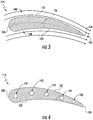
- the airfoil 114 includes a pressure side surface 120 and an opposing suction side surface 122 ( FIG. 3 ).
- the pressure side surface 120 and the suction side surface 122 are joined together or interconnected at a leading edge 124 of the airfoil 114, which is oriented into the flow of combustion gases 34 ( FIG.
- the pressure side surface 120 and the suction side surface 122 are also joined together or interconnected at a trailing edge 126 of the airfoil 114 spaced downstream from the leading edge 124.
- the pressure side surface 120 and the suction side surface 122 are continuous about the leading edge 124 and the trailing edge 126.
- the pressure side surface 120 is generally concave, and the suction side surface 122 is generally convex.
- the airfoil 114 defines a span 128 extending from the root 118 to the tip shroud 116.
- the root 118 is positioned at zero percent of the span 128, and the tip shroud 116 is positioned at one hundred percent of the span 128.
- zero percent of the span 128 is identified by 130, and one hundred percent of the span 128 is identified by 132.
- ninety percent of the span 126 is identified by 134.
- Other positions along the span 128 may be defined as well.
- the airfoil 114 defines a camber line 136. More specifically, the camber line 136 extends from the leading edge 124 to the trailing edge 126. The camber line 136 is also positioned between and equidistant from the pressure side surface 120 and the suction side surface 122. As shown, the airfoil 114 and, more generally, the rotor blade 100 include a pressure side 138 positioned on one side of the camber line 136 and a suction side 140 positioned on the other side of the camber line 136.
- the airfoil 114 may partially define a plurality of cooling passages 142 extending therethrough. In the embodiment shown, the airfoil 114 partially defines five cooling passages 142. In alternate embodiments, however, the airfoil 114 may define more or fewer cooling passages 142.
- the cooling passages 142 extend radially outward from the intake port 112 through the airfoil 114 to the tip shroud 116. In this respect, cooling fluid may flow through the cooling passages 142 from the intake port 112 to the tip shroud 116.
- the rotor blade 100 includes the tip shroud 116.
- the tip shroud 116 couples to the radially outer end of the airfoil 114 and generally defines the radially outermost portion of the rotor blade 100.
- the tip shroud 116 reduces the amount of the combustion gases 34 ( FIG. 1 ) that escape past the rotor blade 100.
- the tip shroud 116 includes a side surface 144 which includes one or more non-radial faces of the tip shroud 116 as discussed herein.
- the tip shroud 116 further includes a radially outer surface 146 and a radially inner surface 148 ( FIG. 6 ). In the embodiment shown in FIG.
- the tip shroud 116 includes a seal rail 152 extending radially outwardly from the radially outer surface 148.
- a seal rail 152 may include more seal rails 152 (e.g., two seal rails 152, three seal rails 152, etc.) or no seal rails 152 at all.
- the side surface 144 includes one or more non-radial faces of the tip shroud 116.
- These non-radial faces may include, for example, a leading edge face 170, a trailing edge face 172, a pressure side face 174, and/or a suction side face 176.
- the leading edge face 170 generally faces the hot gas path 32 and thus is impacted by combustion gases 34 traveling past the blade 100.
- the trailing edge face 172 is generally opposite the leading edge face 170 along the axial direction A.
- the pressure side face 174 and suction side face 176 are generally opposite each other along the circumferential direction C.
- a pressure side face 174 may face the suction side face 176 of a neighboring blade 100, and the suction side face 176 may face the pressure side face 174 of a neighboring blade 100, in a circumferential array of blades 100 in a stage.
- the tip shroud 116 defines various passages, chambers, and apertures to facilitate cooling thereof.
- the seal rail 152 shown in FIG. 2 is omitted from FIG. 5 for clarity.
- the tip shroud 116 defines a central plenum 154.
- the central plenum 154 is fluidly coupled to the cooling passages 142.
- the tip shroud 116 also defines a main body cavity 156.
- One or more cross-over apertures 158 defined by the tip shroud 116 may fluidly couple the central plenum 154 to the main body cavity 156.
- the tip shroud 116 defines one or more outlet apertures 160 that fluidly couple the main body cavity 156 to the hot gas path 32 ( FIG.
- the tip shroud 116 may define any suitable configuration of passages, chambers, and/or apertures.
- the central plenum 154, the main body cavity 156, the cross-over apertures 158, and the outlet apertures 160 may collectively be referred to as a core 162.
- cooling fluid flows through the passages, cavities, and apertures described above to cool the tip shroud 116. More specifically, cooling fluid (e.g., bleed air from the compressor section 14) enters the rotor blade 100 through the intake port 112 ( FIG. 2 ). At least a portion of this cooling flows through the cooling passages 142 and into the central plenum 154 in the tip shroud 116. The cooling fluid then flows from the central plenum 154 through the cross-over apertures 158 into main body cavity 156. While flowing through the main body cavity 156, the cooling fluid convectively cools the various walls of the tip shroud 116. The cooling fluid may then exit the main body cavity 156 through the outlet apertures 160 and flow into the hot gas path 32 ( FIG. 1 ).
- cooling fluid e.g., bleed air from the compressor section 14
- the tip shroud 116 may define a plurality of outlet apertures 160.
- Each outlet aperture 160 may fluidly couple the body cavity 156 to the hot gas path 32, and thus be in fluid communication with and between the body cavity 156 and hot gas path 32. More specifically, cooling fluid may flow from the body cavity 156 through each outlet aperture 160 and be exhausted from each outlet aperture 160 into the hot gas path 32.
- Each outlet aperture 160 may, for example, extend between the body cavity 156 and an opening 161 of the outlet aperture 160 that is defined in an exterior surface of the tip shroud 116. Such exterior surface may be a non-radial face of the side surface 144, the radially outer surface 146, or the radially inner surface 148. Accordingly, cooling fluid in the body cavity 156 may flow from the body cavity 156 into and through each outlet aperture 160, and be exhausted from the outlet aperture 160 through the opening 161 thereof into the hot gas path 32.
- one or more of the outlet apertures 160 may have a particularly advantageous positioning which facilitate improved turbomachine 10 performance.
- cooling fluid exhausted through openings 161' of such outlet apertures 160' may be oriented with the hot gas path 32 direction of flow. Accordingly, such cooling fluid may supply additional thrust. Additionally, such orientation may reduce disturbances in the hot gas path 32 due to such exhausted cooling fluid interacting with the combustion gases 34, such as at various transverse angles, etc. Accordingly, improved aerodynamic performance is facilitated.
- each such one or more first outlet apertures 160' may be oriented to exhaust cooling fluid 180 through the opening 161' thereof in a direction 182 that is within 15 degrees from parallel to the camber line 136 at the trailing edge 126 (i.e. between and including 15 degrees from parallel to the camber line 136 at the trailing edge 126 and parallel to the camber line 136 at the trailing edge 126).
- each such one or more first outlet apertures 160' may be oriented to exhaust cooling fluid 180 through the opening 161' thereof in a direction 182 that is within 10 degrees of parallel to the camber line 136 at the trailing edge 126, such as within 5 degrees of parallel to the camber line 136 at the trailing edge 126, such as parallel to the camber line 136 at the trailing edge 126.
- Such direction 182 may be defined in a top view plane defined partially by the axial direction A and as illustrated in FIG. 5 .
- Angle 184 as illustrated in FIG. 5 , may define such orientation of the direction 182 relative to the camber line 136.
- openings 161' may be defined in exterior surfaces of the tip shroud 116.
- such exterior surface 161' for the first outlet apertures 160' may be a non-radial face.
- such non-radial face may be the trailing edge face 172.
- openings 161' may be defined in other non-radial faces or, for example, the radially outer surface 146 or radially inner surface 148.
- cooling fluid 180 exhausted from first outlet apertures 160' through openings 161' thereof are oriented with the hot gas path 32 direction as the combustion gases 34 flow past the trailing edge 126.
- additional cooling flow 180 may be exhausted through openings 161 of other outlet apertures 160 different from the first outlet apertures 160'.
- the plurality of outlet apertures 160 may further include one or more second outlet apertures 160", and cooling fluid 180 may be exhausted through openings 161" thereof.
- cooling fluid 180 may be exhausted through openings 161" thereof.
- only a portion of the cooling fluid 180 is thus exhausted from first outlet apertures 160' as discussed above, while another portion of the cooling fluid 180 being exhausted from second outlet apertures 160" can be utilized for other purposes.
- some of the cooling fluid 180 being exhausted from second outlet apertures 160" can be utilized for further cooling of the tip shroud 116.
- some of the cooling fluid 180 being exhausted from second outlet apertures 160" can be utilized for impingement cooling of faces of neighboring blades 100, as discussed above.
- each such one or more second outlet apertures 160" may be oriented to exhaust cooling fluid 180 through the opening 161" thereof in a direction 192 that is greater than 15 degrees from parallel to the camber line 136 at the trailing edge 126. Further, in some embodiments, one or more of the second outlet apertures 160" may be oriented to exhaust cooling fluid 180 through the opening 161" thereof in a direction 192 that is greater than 30 degrees from parallel to the camber line 136 at the trailing edge 126, such as greater than 50 degrees from parallel to the camber line 136 at the trailing edge.
- Such direction 192 may be defined in a top view plane defined partially by the axial direction A and as illustrated in FIG. 5 . Angle 184, as illustrated in FIG. 5 , may define such orientation of the direction 192 relative to the camber line 136.
- openings 161" may be defined in exterior surfaces of the tip shroud 116.
- such exterior surface 161" for one or more of the second outlet apertures 160" may be a non-radial face.
- such non-radial face for one or more second outlet apertures 160" may be the leading edge face 170.
- such non-radial face for one or more second outlet apertures 160" may be the pressure side face 174 and/or suction side face 176.
- openings 161" for one or more of the second outlet apertures 160" may be defined in other non-radial faces or, for example, the radially outer surface 146 or radially inner surface 148.
Landscapes
- Engineering & Computer Science (AREA)
- Mechanical Engineering (AREA)
- General Engineering & Computer Science (AREA)
- Turbine Rotor Nozzle Sealing (AREA)
- Chemical & Material Sciences (AREA)
- Combustion & Propulsion (AREA)
- Physics & Mathematics (AREA)
- Fluid Mechanics (AREA)
Applications Claiming Priority (1)
| Application Number | Priority Date | Filing Date | Title |
|---|---|---|---|
| US15/615,876 US10502069B2 (en) | 2017-06-07 | 2017-06-07 | Turbomachine rotor blade |
Publications (2)
| Publication Number | Publication Date |
|---|---|
| EP3412869A1 true EP3412869A1 (de) | 2018-12-12 |
| EP3412869B1 EP3412869B1 (de) | 2021-04-07 |
Family
ID=62495681
Family Applications (1)
| Application Number | Title | Priority Date | Filing Date |
|---|---|---|---|
| EP18175502.6A Active EP3412869B1 (de) | 2017-06-07 | 2018-06-01 | Turbomaschinenrotorschaufel |
Country Status (5)
| Country | Link |
|---|---|
| US (1) | US10502069B2 (de) |
| EP (1) | EP3412869B1 (de) |
| JP (1) | JP7271093B2 (de) |
| KR (1) | KR102699389B1 (de) |
| CN (1) | CN108999647B (de) |
Cited By (1)
| Publication number | Priority date | Publication date | Assignee | Title |
|---|---|---|---|---|
| EP3832071A1 (de) * | 2019-12-04 | 2021-06-09 | Raytheon Technologies Corporation | Strömungspfadkomponente einer gasturbine mit vektorisierten kühlströmungslöchern |
Families Citing this family (1)
| Publication number | Priority date | Publication date | Assignee | Title |
|---|---|---|---|---|
| US11225872B2 (en) * | 2019-11-05 | 2022-01-18 | General Electric Company | Turbine blade with tip shroud cooling passage |
Citations (4)
| Publication number | Priority date | Publication date | Assignee | Title |
|---|---|---|---|---|
| WO1994011616A1 (de) * | 1992-11-19 | 1994-05-26 | Bmw Rolls-Royce Gmbh | Kühlung des deckbandes einer turbinenschaufel |
| GB2298246A (en) * | 1995-02-23 | 1996-08-28 | Bmw Rolls Royce Gmbh | Turbine-blad-tip-sealing arrangement comprising a shroud band |
| US20020150474A1 (en) * | 2001-04-16 | 2002-10-17 | Balkcum J. Tyson | Thin walled cooled hollow tip shroud |
| US6761534B1 (en) * | 1999-04-05 | 2004-07-13 | General Electric Company | Cooling circuit for a gas turbine bucket and tip shroud |
Family Cites Families (29)
| Publication number | Priority date | Publication date | Assignee | Title |
|---|---|---|---|---|
| GB1423833A (en) | 1972-04-20 | 1976-02-04 | Rolls Royce | Rotor blades for fluid flow machines |
| GB1426049A (en) * | 1972-10-21 | 1976-02-25 | Rolls Royce | Rotor blade for a gas turbine engine |
| FR2275975A5 (fr) | 1973-03-20 | 1976-01-16 | Snecma | Perfectionnements au refroidissement d'aubes de turbines a gaz |
| GB1519449A (en) * | 1975-11-10 | 1978-07-26 | Rolls Royce | Gas turbine engine |
| GB1514613A (en) * | 1976-04-08 | 1978-06-14 | Rolls Royce | Blade or vane for a gas turbine engine |
| JPH10266803A (ja) * | 1997-03-25 | 1998-10-06 | Mitsubishi Heavy Ind Ltd | ガスタービン冷却動翼 |
| JPH1113402A (ja) * | 1997-06-23 | 1999-01-19 | Mitsubishi Heavy Ind Ltd | ガスタービン冷却翼チップシュラウド |
| JP3510467B2 (ja) * | 1998-01-13 | 2004-03-29 | 三菱重工業株式会社 | ガスタービンの動翼 |
| EP1041247B1 (de) * | 1999-04-01 | 2012-08-01 | General Electric Company | Gasturbinenschaufel mit einem offenen Kühlkreislauf |
| US6932571B2 (en) * | 2003-02-05 | 2005-08-23 | United Technologies Corporation | Microcircuit cooling for a turbine blade tip |
| EP1591626A1 (de) * | 2004-04-30 | 2005-11-02 | Alstom Technology Ltd | Schaufel für Gasturbine |
| EP1789654B1 (de) * | 2004-09-16 | 2017-08-23 | General Electric Technology GmbH | Strömungsmaschinenschaufel mit fluidisch gekühltem deckband |
| US7413406B2 (en) * | 2006-02-15 | 2008-08-19 | United Technologies Corporation | Turbine blade with radial cooling channels |
| US7686581B2 (en) * | 2006-06-07 | 2010-03-30 | General Electric Company | Serpentine cooling circuit and method for cooling tip shroud |
| US7946817B2 (en) * | 2008-01-10 | 2011-05-24 | General Electric Company | Turbine blade tip shroud |
| US7946816B2 (en) * | 2008-01-10 | 2011-05-24 | General Electric Company | Turbine blade tip shroud |
| US8057177B2 (en) * | 2008-01-10 | 2011-11-15 | General Electric Company | Turbine blade tip shroud |
| US8348612B2 (en) * | 2008-01-10 | 2013-01-08 | General Electric Company | Turbine blade tip shroud |
| US8096772B2 (en) * | 2009-03-20 | 2012-01-17 | Siemens Energy, Inc. | Turbine vane for a gas turbine engine having serpentine cooling channels within the inner endwall |
| US8684692B2 (en) * | 2010-02-05 | 2014-04-01 | Siemens Energy, Inc. | Cooled snubber structure for turbine blades |
| US8672613B2 (en) * | 2010-08-31 | 2014-03-18 | General Electric Company | Components with conformal curved film holes and methods of manufacture |
| US9022736B2 (en) * | 2011-02-15 | 2015-05-05 | Siemens Energy, Inc. | Integrated axial and tangential serpentine cooling circuit in a turbine airfoil |
| JP5868609B2 (ja) | 2011-04-18 | 2016-02-24 | 三菱重工業株式会社 | ガスタービン動翼及びその製造方法 |
| JP5916294B2 (ja) * | 2011-04-18 | 2016-05-11 | 三菱重工業株式会社 | ガスタービン動翼及びその製造方法 |
| US9127560B2 (en) * | 2011-12-01 | 2015-09-08 | General Electric Company | Cooled turbine blade and method for cooling a turbine blade |
| EP2607629A1 (de) | 2011-12-22 | 2013-06-26 | Alstom Technology Ltd | Turbinenschaufel mit Deckband und Kühlluftauslassöffnung an der Schaufelspitze und zugehöriges Herstellungsverfahren |
| US11230935B2 (en) * | 2015-09-18 | 2022-01-25 | General Electric Company | Stator component cooling |
| US9885243B2 (en) * | 2015-10-27 | 2018-02-06 | General Electric Company | Turbine bucket having outlet path in shroud |
| US10215028B2 (en) * | 2016-03-07 | 2019-02-26 | Rolls-Royce North American Technologies Inc. | Turbine blade with heat shield |
-
2017
- 2017-06-07 US US15/615,876 patent/US10502069B2/en active Active
-
2018
- 2018-05-31 JP JP2018104177A patent/JP7271093B2/ja active Active
- 2018-06-01 EP EP18175502.6A patent/EP3412869B1/de active Active
- 2018-06-05 KR KR1020180064720A patent/KR102699389B1/ko active Active
- 2018-06-07 CN CN201810580848.4A patent/CN108999647B/zh active Active
Patent Citations (4)
| Publication number | Priority date | Publication date | Assignee | Title |
|---|---|---|---|---|
| WO1994011616A1 (de) * | 1992-11-19 | 1994-05-26 | Bmw Rolls-Royce Gmbh | Kühlung des deckbandes einer turbinenschaufel |
| GB2298246A (en) * | 1995-02-23 | 1996-08-28 | Bmw Rolls Royce Gmbh | Turbine-blad-tip-sealing arrangement comprising a shroud band |
| US6761534B1 (en) * | 1999-04-05 | 2004-07-13 | General Electric Company | Cooling circuit for a gas turbine bucket and tip shroud |
| US20020150474A1 (en) * | 2001-04-16 | 2002-10-17 | Balkcum J. Tyson | Thin walled cooled hollow tip shroud |
Cited By (2)
| Publication number | Priority date | Publication date | Assignee | Title |
|---|---|---|---|---|
| EP3832071A1 (de) * | 2019-12-04 | 2021-06-09 | Raytheon Technologies Corporation | Strömungspfadkomponente einer gasturbine mit vektorisierten kühlströmungslöchern |
| US11415020B2 (en) | 2019-12-04 | 2022-08-16 | Raytheon Technologies Corporation | Gas turbine engine flowpath component including vectored cooling flow holes |
Also Published As
| Publication number | Publication date |
|---|---|
| CN108999647A (zh) | 2018-12-14 |
| KR102699389B1 (ko) | 2024-08-28 |
| CN108999647B (zh) | 2022-08-02 |
| US10502069B2 (en) | 2019-12-10 |
| KR20180133805A (ko) | 2018-12-17 |
| JP7271093B2 (ja) | 2023-05-11 |
| US20180355729A1 (en) | 2018-12-13 |
| JP2019023462A (ja) | 2019-02-14 |
| EP3412869B1 (de) | 2021-04-07 |
Similar Documents
| Publication | Publication Date | Title |
|---|---|---|
| US10107108B2 (en) | Rotor blade having a flared tip | |
| US10830082B2 (en) | Systems including rotor blade tips and circumferentially grooved shrouds | |
| EP3415719B1 (de) | Kühlstruktur einer turbomaschinenschaufel | |
| EP3088674A1 (de) | Rotorblatt und zugehörige gasturbine | |
| US20170234142A1 (en) | Rotor Blade Trailing Edge Cooling | |
| US10301943B2 (en) | Turbomachine rotor blade | |
| EP3203024A1 (de) | Laufschaufel und zugehörige gasturbine | |
| EP3249162B1 (de) | Laufschaufel und zugehöriges gasturbinensystem | |
| EP3885532B1 (de) | Turbinenlaufschaufel mit kühlkreislauf | |
| EP3418496B1 (de) | Turbomaschinenrotorschaufel | |
| EP3412869B1 (de) | Turbomaschinenrotorschaufel | |
| US10494932B2 (en) | Turbomachine rotor blade cooling passage | |
| US10472974B2 (en) | Turbomachine rotor blade | |
| US10590777B2 (en) | Turbomachine rotor blade | |
| US11629601B2 (en) | Turbomachine rotor blade with a cooling circuit having an offset rib | |
| US10577945B2 (en) | Turbomachine rotor blade | |
| US20170122111A1 (en) | Turbine airfoil internal core profile | |
| US20190003320A1 (en) | Turbomachine rotor blade | |
| US10746029B2 (en) | Turbomachine rotor blade tip shroud cavity | |
| US10633979B2 (en) | Turbomachine rotor blade pocket | |
| US20180216474A1 (en) | Turbomachine Blade Cooling Cavity |
Legal Events
| Date | Code | Title | Description |
|---|---|---|---|
| PUAI | Public reference made under article 153(3) epc to a published international application that has entered the european phase |
Free format text: ORIGINAL CODE: 0009012 |
|
| STAA | Information on the status of an ep patent application or granted ep patent |
Free format text: STATUS: THE APPLICATION HAS BEEN PUBLISHED |
|
| AK | Designated contracting states |
Kind code of ref document: A1 Designated state(s): AL AT BE BG CH CY CZ DE DK EE ES FI FR GB GR HR HU IE IS IT LI LT LU LV MC MK MT NL NO PL PT RO RS SE SI SK SM TR |
|
| AX | Request for extension of the european patent |
Extension state: BA ME |
|
| STAA | Information on the status of an ep patent application or granted ep patent |
Free format text: STATUS: REQUEST FOR EXAMINATION WAS MADE |
|
| 17P | Request for examination filed |
Effective date: 20190607 |
|
| RBV | Designated contracting states (corrected) |
Designated state(s): AL AT BE BG CH CY CZ DE DK EE ES FI FR GB GR HR HU IE IS IT LI LT LU LV MC MK MT NL NO PL PT RO RS SE SI SK SM TR |
|
| RIC1 | Information provided on ipc code assigned before grant |
Ipc: F01D 5/18 20060101AFI20200918BHEP Ipc: F01D 5/22 20060101ALI20200918BHEP |
|
| GRAP | Despatch of communication of intention to grant a patent |
Free format text: ORIGINAL CODE: EPIDOSNIGR1 |
|
| STAA | Information on the status of an ep patent application or granted ep patent |
Free format text: STATUS: GRANT OF PATENT IS INTENDED |
|
| INTG | Intention to grant announced |
Effective date: 20201109 |
|
| GRAS | Grant fee paid |
Free format text: ORIGINAL CODE: EPIDOSNIGR3 |
|
| GRAA | (expected) grant |
Free format text: ORIGINAL CODE: 0009210 |
|
| STAA | Information on the status of an ep patent application or granted ep patent |
Free format text: STATUS: THE PATENT HAS BEEN GRANTED |
|
| AK | Designated contracting states |
Kind code of ref document: B1 Designated state(s): AL AT BE BG CH CY CZ DE DK EE ES FI FR GB GR HR HU IE IS IT LI LT LU LV MC MK MT NL NO PL PT RO RS SE SI SK SM TR |
|
| REG | Reference to a national code |
Ref country code: GB Ref legal event code: FG4D |
|
| REG | Reference to a national code |
Ref country code: AT Ref legal event code: REF Ref document number: 1379930 Country of ref document: AT Kind code of ref document: T Effective date: 20210415 Ref country code: CH Ref legal event code: EP |
|
| REG | Reference to a national code |
Ref country code: DE Ref legal event code: R096 Ref document number: 602018015006 Country of ref document: DE |
|
| REG | Reference to a national code |
Ref country code: IE Ref legal event code: FG4D |
|
| REG | Reference to a national code |
Ref country code: LT Ref legal event code: MG9D |
|
| REG | Reference to a national code |
Ref country code: NL Ref legal event code: MP Effective date: 20210407 Ref country code: AT Ref legal event code: MK05 Ref document number: 1379930 Country of ref document: AT Kind code of ref document: T Effective date: 20210407 |
|
| PG25 | Lapsed in a contracting state [announced via postgrant information from national office to epo] |
Ref country code: FI Free format text: LAPSE BECAUSE OF FAILURE TO SUBMIT A TRANSLATION OF THE DESCRIPTION OR TO PAY THE FEE WITHIN THE PRESCRIBED TIME-LIMIT Effective date: 20210407 Ref country code: HR Free format text: LAPSE BECAUSE OF FAILURE TO SUBMIT A TRANSLATION OF THE DESCRIPTION OR TO PAY THE FEE WITHIN THE PRESCRIBED TIME-LIMIT Effective date: 20210407 Ref country code: LT Free format text: LAPSE BECAUSE OF FAILURE TO SUBMIT A TRANSLATION OF THE DESCRIPTION OR TO PAY THE FEE WITHIN THE PRESCRIBED TIME-LIMIT Effective date: 20210407 Ref country code: AT Free format text: LAPSE BECAUSE OF FAILURE TO SUBMIT A TRANSLATION OF THE DESCRIPTION OR TO PAY THE FEE WITHIN THE PRESCRIBED TIME-LIMIT Effective date: 20210407 Ref country code: BG Free format text: LAPSE BECAUSE OF FAILURE TO SUBMIT A TRANSLATION OF THE DESCRIPTION OR TO PAY THE FEE WITHIN THE PRESCRIBED TIME-LIMIT Effective date: 20210707 Ref country code: NL Free format text: LAPSE BECAUSE OF FAILURE TO SUBMIT A TRANSLATION OF THE DESCRIPTION OR TO PAY THE FEE WITHIN THE PRESCRIBED TIME-LIMIT Effective date: 20210407 |
|
| PG25 | Lapsed in a contracting state [announced via postgrant information from national office to epo] |
Ref country code: IS Free format text: LAPSE BECAUSE OF FAILURE TO SUBMIT A TRANSLATION OF THE DESCRIPTION OR TO PAY THE FEE WITHIN THE PRESCRIBED TIME-LIMIT Effective date: 20210807 Ref country code: GR Free format text: LAPSE BECAUSE OF FAILURE TO SUBMIT A TRANSLATION OF THE DESCRIPTION OR TO PAY THE FEE WITHIN THE PRESCRIBED TIME-LIMIT Effective date: 20210708 Ref country code: SE Free format text: LAPSE BECAUSE OF FAILURE TO SUBMIT A TRANSLATION OF THE DESCRIPTION OR TO PAY THE FEE WITHIN THE PRESCRIBED TIME-LIMIT Effective date: 20210407 Ref country code: RS Free format text: LAPSE BECAUSE OF FAILURE TO SUBMIT A TRANSLATION OF THE DESCRIPTION OR TO PAY THE FEE WITHIN THE PRESCRIBED TIME-LIMIT Effective date: 20210407 Ref country code: PL Free format text: LAPSE BECAUSE OF FAILURE TO SUBMIT A TRANSLATION OF THE DESCRIPTION OR TO PAY THE FEE WITHIN THE PRESCRIBED TIME-LIMIT Effective date: 20210407 Ref country code: LV Free format text: LAPSE BECAUSE OF FAILURE TO SUBMIT A TRANSLATION OF THE DESCRIPTION OR TO PAY THE FEE WITHIN THE PRESCRIBED TIME-LIMIT Effective date: 20210407 Ref country code: PT Free format text: LAPSE BECAUSE OF FAILURE TO SUBMIT A TRANSLATION OF THE DESCRIPTION OR TO PAY THE FEE WITHIN THE PRESCRIBED TIME-LIMIT Effective date: 20210809 Ref country code: NO Free format text: LAPSE BECAUSE OF FAILURE TO SUBMIT A TRANSLATION OF THE DESCRIPTION OR TO PAY THE FEE WITHIN THE PRESCRIBED TIME-LIMIT Effective date: 20210707 |
|
| REG | Reference to a national code |
Ref country code: DE Ref legal event code: R097 Ref document number: 602018015006 Country of ref document: DE |
|
| PG25 | Lapsed in a contracting state [announced via postgrant information from national office to epo] |
Ref country code: SK Free format text: LAPSE BECAUSE OF FAILURE TO SUBMIT A TRANSLATION OF THE DESCRIPTION OR TO PAY THE FEE WITHIN THE PRESCRIBED TIME-LIMIT Effective date: 20210407 Ref country code: SM Free format text: LAPSE BECAUSE OF FAILURE TO SUBMIT A TRANSLATION OF THE DESCRIPTION OR TO PAY THE FEE WITHIN THE PRESCRIBED TIME-LIMIT Effective date: 20210407 Ref country code: EE Free format text: LAPSE BECAUSE OF FAILURE TO SUBMIT A TRANSLATION OF THE DESCRIPTION OR TO PAY THE FEE WITHIN THE PRESCRIBED TIME-LIMIT Effective date: 20210407 Ref country code: ES Free format text: LAPSE BECAUSE OF FAILURE TO SUBMIT A TRANSLATION OF THE DESCRIPTION OR TO PAY THE FEE WITHIN THE PRESCRIBED TIME-LIMIT Effective date: 20210407 Ref country code: DK Free format text: LAPSE BECAUSE OF FAILURE TO SUBMIT A TRANSLATION OF THE DESCRIPTION OR TO PAY THE FEE WITHIN THE PRESCRIBED TIME-LIMIT Effective date: 20210407 Ref country code: CZ Free format text: LAPSE BECAUSE OF FAILURE TO SUBMIT A TRANSLATION OF THE DESCRIPTION OR TO PAY THE FEE WITHIN THE PRESCRIBED TIME-LIMIT Effective date: 20210407 Ref country code: MC Free format text: LAPSE BECAUSE OF FAILURE TO SUBMIT A TRANSLATION OF THE DESCRIPTION OR TO PAY THE FEE WITHIN THE PRESCRIBED TIME-LIMIT Effective date: 20210407 Ref country code: RO Free format text: LAPSE BECAUSE OF FAILURE TO SUBMIT A TRANSLATION OF THE DESCRIPTION OR TO PAY THE FEE WITHIN THE PRESCRIBED TIME-LIMIT Effective date: 20210407 |
|
| REG | Reference to a national code |
Ref country code: CH Ref legal event code: PL |
|
| PLBE | No opposition filed within time limit |
Free format text: ORIGINAL CODE: 0009261 |
|
| STAA | Information on the status of an ep patent application or granted ep patent |
Free format text: STATUS: NO OPPOSITION FILED WITHIN TIME LIMIT |
|
| REG | Reference to a national code |
Ref country code: BE Ref legal event code: MM Effective date: 20210630 |
|
| 26N | No opposition filed |
Effective date: 20220110 |
|
| PG25 | Lapsed in a contracting state [announced via postgrant information from national office to epo] |
Ref country code: LU Free format text: LAPSE BECAUSE OF NON-PAYMENT OF DUE FEES Effective date: 20210601 |
|
| PG25 | Lapsed in a contracting state [announced via postgrant information from national office to epo] |
Ref country code: LI Free format text: LAPSE BECAUSE OF NON-PAYMENT OF DUE FEES Effective date: 20210630 Ref country code: IE Free format text: LAPSE BECAUSE OF NON-PAYMENT OF DUE FEES Effective date: 20210601 Ref country code: CH Free format text: LAPSE BECAUSE OF NON-PAYMENT OF DUE FEES Effective date: 20210630 |
|
| PG25 | Lapsed in a contracting state [announced via postgrant information from national office to epo] |
Ref country code: IS Free format text: LAPSE BECAUSE OF FAILURE TO SUBMIT A TRANSLATION OF THE DESCRIPTION OR TO PAY THE FEE WITHIN THE PRESCRIBED TIME-LIMIT Effective date: 20210807 Ref country code: FR Free format text: LAPSE BECAUSE OF NON-PAYMENT OF DUE FEES Effective date: 20210607 Ref country code: AL Free format text: LAPSE BECAUSE OF FAILURE TO SUBMIT A TRANSLATION OF THE DESCRIPTION OR TO PAY THE FEE WITHIN THE PRESCRIBED TIME-LIMIT Effective date: 20210407 |
|
| PG25 | Lapsed in a contracting state [announced via postgrant information from national office to epo] |
Ref country code: BE Free format text: LAPSE BECAUSE OF NON-PAYMENT OF DUE FEES Effective date: 20210630 |
|
| GBPC | Gb: european patent ceased through non-payment of renewal fee |
Effective date: 20220601 |
|
| PG25 | Lapsed in a contracting state [announced via postgrant information from national office to epo] |
Ref country code: GB Free format text: LAPSE BECAUSE OF NON-PAYMENT OF DUE FEES Effective date: 20220601 |
|
| PG25 | Lapsed in a contracting state [announced via postgrant information from national office to epo] |
Ref country code: CY Free format text: LAPSE BECAUSE OF FAILURE TO SUBMIT A TRANSLATION OF THE DESCRIPTION OR TO PAY THE FEE WITHIN THE PRESCRIBED TIME-LIMIT Effective date: 20210407 |
|
| PG25 | Lapsed in a contracting state [announced via postgrant information from national office to epo] |
Ref country code: HU Free format text: LAPSE BECAUSE OF FAILURE TO SUBMIT A TRANSLATION OF THE DESCRIPTION OR TO PAY THE FEE WITHIN THE PRESCRIBED TIME-LIMIT; INVALID AB INITIO Effective date: 20180601 |
|
| REG | Reference to a national code |
Ref country code: DE Ref legal event code: R081 Ref document number: 602018015006 Country of ref document: DE Owner name: GENERAL ELECTRIC TECHNOLOGY GMBH, CH Free format text: FORMER OWNER: GENERAL ELECTRIC COMPANY, SCHENECTADY, NY, US |
|
| PG25 | Lapsed in a contracting state [announced via postgrant information from national office to epo] |
Ref country code: MK Free format text: LAPSE BECAUSE OF FAILURE TO SUBMIT A TRANSLATION OF THE DESCRIPTION OR TO PAY THE FEE WITHIN THE PRESCRIBED TIME-LIMIT Effective date: 20210407 |
|
| PG25 | Lapsed in a contracting state [announced via postgrant information from national office to epo] |
Ref country code: MT Free format text: LAPSE BECAUSE OF FAILURE TO SUBMIT A TRANSLATION OF THE DESCRIPTION OR TO PAY THE FEE WITHIN THE PRESCRIBED TIME-LIMIT Effective date: 20210407 |
|
| PGFP | Annual fee paid to national office [announced via postgrant information from national office to epo] |
Ref country code: DE Payment date: 20250520 Year of fee payment: 8 |
|
| PGFP | Annual fee paid to national office [announced via postgrant information from national office to epo] |
Ref country code: IT Payment date: 20250520 Year of fee payment: 8 |
|
| PG25 | Lapsed in a contracting state [announced via postgrant information from national office to epo] |
Ref country code: TR Free format text: LAPSE BECAUSE OF FAILURE TO SUBMIT A TRANSLATION OF THE DESCRIPTION OR TO PAY THE FEE WITHIN THE PRESCRIBED TIME-LIMIT Effective date: 20210407 |