EP3412870B1 - Extrémité d'aube de turbine comportant des trous de purge oblongues - Google Patents
Extrémité d'aube de turbine comportant des trous de purge oblongues Download PDFInfo
- Publication number
- EP3412870B1 EP3412870B1 EP18174121.6A EP18174121A EP3412870B1 EP 3412870 B1 EP3412870 B1 EP 3412870B1 EP 18174121 A EP18174121 A EP 18174121A EP 3412870 B1 EP3412870 B1 EP 3412870B1
- Authority
- EP
- European Patent Office
- Prior art keywords
- opening
- dimension
- tip
- turbine
- turbine blade
- Prior art date
- Legal status (The legal status is an assumption and is not a legal conclusion. Google has not performed a legal analysis and makes no representation as to the accuracy of the status listed.)
- Active
Links
Images




Classifications
-
- F—MECHANICAL ENGINEERING; LIGHTING; HEATING; WEAPONS; BLASTING
- F01—MACHINES OR ENGINES IN GENERAL; ENGINE PLANTS IN GENERAL; STEAM ENGINES
- F01D—NON-POSITIVE DISPLACEMENT MACHINES OR ENGINES, e.g. STEAM TURBINES
- F01D5/00—Blades; Blade-carrying members; Heating, heat-insulating, cooling or antivibration means on the blades or the members
- F01D5/12—Blades
- F01D5/14—Form or construction
- F01D5/20—Specially-shaped blade tips to seal space between tips and stator
-
- F—MECHANICAL ENGINEERING; LIGHTING; HEATING; WEAPONS; BLASTING
- F01—MACHINES OR ENGINES IN GENERAL; ENGINE PLANTS IN GENERAL; STEAM ENGINES
- F01D—NON-POSITIVE DISPLACEMENT MACHINES OR ENGINES, e.g. STEAM TURBINES
- F01D5/00—Blades; Blade-carrying members; Heating, heat-insulating, cooling or antivibration means on the blades or the members
- F01D5/12—Blades
- F01D5/14—Form or construction
- F01D5/147—Construction, i.e. structural features, e.g. of weight-saving hollow blades
-
- F—MECHANICAL ENGINEERING; LIGHTING; HEATING; WEAPONS; BLASTING
- F01—MACHINES OR ENGINES IN GENERAL; ENGINE PLANTS IN GENERAL; STEAM ENGINES
- F01D—NON-POSITIVE DISPLACEMENT MACHINES OR ENGINES, e.g. STEAM TURBINES
- F01D5/00—Blades; Blade-carrying members; Heating, heat-insulating, cooling or antivibration means on the blades or the members
- F01D5/12—Blades
- F01D5/14—Form or construction
- F01D5/18—Hollow blades, i.e. blades with cooling or heating channels or cavities; Heating, heat-insulating or cooling means on blades
- F01D5/187—Convection cooling
-
- F—MECHANICAL ENGINEERING; LIGHTING; HEATING; WEAPONS; BLASTING
- F01—MACHINES OR ENGINES IN GENERAL; ENGINE PLANTS IN GENERAL; STEAM ENGINES
- F01D—NON-POSITIVE DISPLACEMENT MACHINES OR ENGINES, e.g. STEAM TURBINES
- F01D5/00—Blades; Blade-carrying members; Heating, heat-insulating, cooling or antivibration means on the blades or the members
- F01D5/12—Blades
- F01D5/14—Form or construction
- F01D5/18—Hollow blades, i.e. blades with cooling or heating channels or cavities; Heating, heat-insulating or cooling means on blades
-
- F—MECHANICAL ENGINEERING; LIGHTING; HEATING; WEAPONS; BLASTING
- F05—INDEXING SCHEMES RELATING TO ENGINES OR PUMPS IN VARIOUS SUBCLASSES OF CLASSES F01-F04
- F05D—INDEXING SCHEME FOR ASPECTS RELATING TO NON-POSITIVE-DISPLACEMENT MACHINES OR ENGINES, GAS-TURBINES OR JET-PROPULSION PLANTS
- F05D2240/00—Components
- F05D2240/20—Rotors
- F05D2240/30—Characteristics of rotor blades, i.e. of any element transforming dynamic fluid energy to or from rotational energy and being attached to a rotor
- F05D2240/307—Characteristics of rotor blades, i.e. of any element transforming dynamic fluid energy to or from rotational energy and being attached to a rotor related to the tip of a rotor blade
-
- F—MECHANICAL ENGINEERING; LIGHTING; HEATING; WEAPONS; BLASTING
- F05—INDEXING SCHEMES RELATING TO ENGINES OR PUMPS IN VARIOUS SUBCLASSES OF CLASSES F01-F04
- F05D—INDEXING SCHEME FOR ASPECTS RELATING TO NON-POSITIVE-DISPLACEMENT MACHINES OR ENGINES, GAS-TURBINES OR JET-PROPULSION PLANTS
- F05D2250/00—Geometry
- F05D2250/10—Two-dimensional
- F05D2250/12—Two-dimensional rectangular
-
- F—MECHANICAL ENGINEERING; LIGHTING; HEATING; WEAPONS; BLASTING
- F05—INDEXING SCHEMES RELATING TO ENGINES OR PUMPS IN VARIOUS SUBCLASSES OF CLASSES F01-F04
- F05D—INDEXING SCHEME FOR ASPECTS RELATING TO NON-POSITIVE-DISPLACEMENT MACHINES OR ENGINES, GAS-TURBINES OR JET-PROPULSION PLANTS
- F05D2250/00—Geometry
- F05D2250/10—Two-dimensional
- F05D2250/14—Two-dimensional elliptical
-
- Y—GENERAL TAGGING OF NEW TECHNOLOGICAL DEVELOPMENTS; GENERAL TAGGING OF CROSS-SECTIONAL TECHNOLOGIES SPANNING OVER SEVERAL SECTIONS OF THE IPC; TECHNICAL SUBJECTS COVERED BY FORMER USPC CROSS-REFERENCE ART COLLECTIONS [XRACs] AND DIGESTS
- Y02—TECHNOLOGIES OR APPLICATIONS FOR MITIGATION OR ADAPTATION AGAINST CLIMATE CHANGE
- Y02T—CLIMATE CHANGE MITIGATION TECHNOLOGIES RELATED TO TRANSPORTATION
- Y02T50/00—Aeronautics or air transport
- Y02T50/60—Efficient propulsion technologies, e.g. for aircraft
Definitions
- the present disclosure relates generally to components of gas turbine engines and, more specifically, to turbine blades including tip walls with oblong openings.
- a gas turbine engine typically includes a fan section, a compressor section, a combustor section, and a turbine section. Air entering the compressor section is compressed and delivered into the combustion section where it is mixed with fuel and ignited to generate a high-speed exhaust gas flow. The high-speed exhaust gas flow expands through the turbine section to drive the compressor and the fan section.
- the compressor section and/or the turbine section may include rotatable blades and stationary vanes.
- a blade outer air seal (BOAS) may be mounted within the engine casing, and positioned in close proximity to the outermost tips of the rotatable blades. Space between the BOAS and the blade tips may be maintained to avoid the blade tips rubbing against the BOAS due to the expansion of the blade relative to the BOAS.
- the efficiency of the gas turbine engine may be undesirably affected by having a large tip clearance between the blade tips and the BOAS, as the hot gas flow may leak through the space between the blade tip and the BOAS.
- US 7597539 B1 discloses a turbine blade having a squealer tip including a trailing edge tip rail and angled cooling holes.
- US 5864949 A discloses a cavity located adjacent a tip surface discharge port of an internal cooling passage of an airfoil of a turbine blade of a gas turbine engine.
- US 2016/230564 A1 discloses a turbine blade including a platform, an airfoil tip and an airfoil section between the platform and the airfoil tip.
- EP 31389979 A1 discloses a rotor blade for a turbine of a gas turbine system including an airfoil, a tip and a rail gap.
- EP 3009600 A1 discloses an airfoil for a gas turbine engine including pressure and suction walls that are joined to provide an airfoil that has a tip with a film cooling hole.
- a turbine blade as claimed in claim 1 is provided.
- proximal refers to a direction inward, or generally, towards the reference component.
- a first component that is "radially outward" of a second component means that the first component is positioned at a greater distance away from the engine central longitudinal axis than the second component.
- a first component that is “radially inward” of a second component means that the first component is positioned closer to the engine central longitudinal axis than the second component.
- a first component that is radially inward of a second component rotates through a circumferentially shorter path than the second component.
- the terminology “radially outward” and “radially inward” may also be used relative to references other than the engine central longitudinal axis.
- Gas turbine engine 20 may be a two-spool turbofan that generally incorporates a fan section 22, a compressor section 24, a combustor section 26, and a turbine section 28.
- Alternative engines may include, for example, an augmentor section among other systems or features.
- fan section 22 can drive coolant (e.g., air) along a path of bypass airflow B while compressor section 24 can drive coolant along a core flowpath C for compression and communication into combustor section 26 then expansion through turbine section 28.
- coolant e.g., air
- compressor section 24 can drive coolant along a core flowpath C for compression and communication into combustor section 26 then expansion through turbine section 28.
- Gas turbine engine 20 may generally comprise a low speed spool 30 and a high speed spool 32 mounted for rotation about an engine central longitudinal axis A-A' relative to an engine static structure 36 (also referred to as an engine casing structure) via several bearing systems 38, 38-1, and 38-2.
- Engine central longitudinal axis A-A' is oriented in the z direction on the provided xyz axes. It should be understood that various bearing systems 38 at various locations may alternatively or additionally be provided, including for example, bearing system 38, bearing system 38-1, and bearing system 38-2.
- Low speed spool 30 may generally comprise an inner shaft 40 that interconnects a fan 42, a low pressure compressor 44, and a low pressure turbine 46.
- Inner shaft 40 may be connected to fan 42 through a geared architecture 48 that can drive fan 42 at a lower speed than low speed spool 30.
- Geared architecture 48 may comprise a gear assembly 60 enclosed within a gear housing 62.
- Gear assembly 60 couples inner shaft 40 to a rotating fan structure.
- High speed spool 32 may comprise an outer shaft 50 that interconnects a high pressure compressor 52 and high pressure turbine 54. As used herein, a "high pressure" compressor or turbine experiences a higher pressure than a corresponding "low pressure” compressor or turbine.
- a combustor 56 may be located between high pressure compressor 52 and high pressure turbine 54.
- a mid-turbine frame 57 of engine casing structure 36 may be located generally between high pressure turbine 54 and low pressure turbine 46.
- Mid-turbine frame 57 may support one or more bearing systems 38 in turbine section 28.
- Inner shaft 40 and outer shaft 50 may be concentric and rotate via bearing systems 38 about the engine central longitudinal axis A-A', which is collinear with their longitudinal axes.
- the core airflow C may be compressed by low pressure compressor 44 then high pressure compressor 52, mixed and burned with fuel in combustor 56, then expanded over high pressure turbine 54 and low pressure turbine 46.
- Turbines 46, 54 rotationally drive the respective low speed spool 30 and high speed spool 32 in response to the expansion.
- Gas turbine engine 20 may be, for example, a high-bypass ratio geared aircraft engine. In various embodiments, the bypass ratio of gas turbine engine 20 may be greater than about six (6). In various embodiments, the bypass ratio of gas turbine engine 20 may be greater than ten (10).
- geared architecture 48 may be an epicyclic gear train, such as a star gear system (sun gear in meshing engagement with a plurality of star gears supported by a carrier and in meshing engagement with a ring gear) or other gear system. Geared architecture 48 may have a gear reduction ratio of greater than about 2.3 and low pressure turbine 46 may have a pressure ratio that is greater than about five (5). In various embodiments, the bypass ratio of gas turbine engine 20 is greater than about ten (10:1).
- the diameter of fan 42 may be significantly larger than that of the low pressure compressor 44, and the low pressure turbine 46 may have a pressure ratio that is greater than about five (5:1).
- Low pressure turbine 46 pressure ratio may be measured prior to inlet of low pressure turbine 46 as related to the pressure at the outlet of low pressure turbine 46 prior to an exhaust nozzle.
- a gas turbine engine may comprise an industrial gas turbine (IGT) or a geared aircraft engine, such as a geared turbofan, or non-geared aircraft engine, such as a turbofan, or may comprise any gas turbine engine as desired.
- IGT industrial gas turbine
- a geared aircraft engine such as a geared turbofan
- non-geared aircraft engine such as a turbofan
- Each of the compressor section 24 and the turbine section 28 may include alternating rows of rotor assemblies and vane assemblies (shown schematically) that carry airfoils that extend into the core flow path C.
- the rotor assemblies in the turbine section 28 may carry a plurality of rotating blades 100
- each vane assembly may carry a plurality of stationary vanes 27 that extend into the core flow path C.
- the blades 100 of the rotor assemblies in the turbine section create or extract energy (in the form of pressure) from the core airflow that is communicated through the gas turbine engine 20 along the core flow path C.
- the vanes 27 of the vane assemblies direct the core airflow to the blades 100 to either add or extract energy.
- Various components of a gas turbine engine 20, including but not limited to the blades 100 and the vanes 27 of the compressor section 24 and the turbine section 28, may be subjected to repetitive thermal cycling under widely ranging temperatures and pressures.
- the hardware of the turbine section 28 is particularly subjected to relatively extreme operating conditions. Therefore, some components may require internal cooling circuits for cooling the parts during engine operation.
- Turbine blades of the present disclosure may include oblong openings formed in the tip of the turbine blade.
- the oblong openings may be positioned with a longer dimension of the openings extending generally from a leading edge toward a trailing edge.
- the oblong shape of the openings may cool and protect a greater area of the blade, as compared to circular-shaped openings of the same surface area.
- the oblong shape of the openings may also decrease gas leakage over the blade tip, which may lead to increased engine efficiency.
- FIG. 2 is a perspective of a turbine rotor section 110 of gas turbine engine 20 in FIG. 1 , as viewed forward to aft.
- the turbine rotor section 110 includes a blade outer air seal (BOAS) 120 surrounding a turbine rotor assembly 130.
- Turbine rotor assembly 130 may comprise a blade ring 132, a turbine disk 134, and a plurality of blades 100. Blades 100 may be coupled to turbine disk 134.
- BOAS 120 may be configured as a cylindrical shroud and may be disposed concentric to turbine rotor assembly 130.
- a radial gap (i.e., a blade running clearance) may be located between an outermost diameter of turbine rotor assembly 130 and BOAS 120 (i.e., between a tip end of blades 100 and a radially inward surface of BOAS 120).
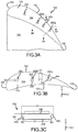
- FIGs. 3A and 3B illustrate a perspective pressure side view and a plan view, respectively, of a turbine blade 100 having oblong openings, in accordance with an illustrative non-claimed example.
- Blade 100 comprises a pressure side wall 150 (also referred to as a pressure side), a suction side wall 152 (also referred to as a suction side) opposite the pressure side wall 150, and a tip wall 154 (also referred to as a blade tip) extending between the pressure side wall 150 and the suction side wall 152.
- pressure side wall 150 may be concave and suction side wall 152 may be convex.
- Blade 100 further comprises a leading edge 156 and a trailing edge 158 opposite the leading edge 156.
- Leading edge 156 may be oriented forward of trailing edge 158.
- a radially outward surface 155 of tip wall 154 may extend between leading edge 156 and trailing edge 158 and between pressure side 150 and suction side 152.
- Tip wall 154 and surface 155 may be oriented radially inward of BOAS 120, with momentary reference to FIG. 2 , and away from engine central longitudinal axis A-A', with momentary reference to FIG. 1 .
- Openings 200 may be formed in tip wall 154 using any suitable manner. Openings 200 may be formed during the manufacturing of blade 100.
- manufacturing blade 100 may comprise forming a ceramic core and then pouring a metal around the ceramic core. Rods may be placed in the mold when the ceramic core is formed, and the ceramic core may harden with the rods attached therein. The rods may hold the ceramic core in place while the metal, which will ultimately form the blade, is poured. The rods tend to prevent the ceramic core from moving during application of the metal. Preventing movement of the ceramic core tends to increase wall thickness precision and wall thickness accuracy when forming blades 100. Once the metal cools and/or hardens, the ceramic core and rods are removed by leaching, leaving the metal blade.
- a location of openings 200 corresponds to the location of the rods in the ceramic core
- a shape of openings 200 corresponds to the shape of the rods.
- FIG. 3C illustrates an opening 200.
- Opening 200 (and the rods that form openings 200) is oblong.
- a first dimension D1 of opening 200 according to the present invention is greater than a second dimension D2 of opening 200.
- a ratio of dimension D1 to dimension D2 may be between 1.5:1 and 15:1.
- a ratio of dimension D1 to dimension D2 may be between 2:1 and 10:1.
- Opening 200 may comprise a first semi-circular end 202 and a second semi-circular end 204 opposite first semi-circular end 202.
- First semi-circular end 202 may have a radius R1.
- Second semi-circular end 204 may have a radius R2.
- radius R1 may be equal to radius R2.
- a first sidewall 206 and a second sidewall 208 may connect semi-circular ends 202 and 204.
- First sidewall 206 may be parallel to second sidewall 208.
- Sidewall 206 may include a length L1 that extends from first semi-circular end 202 to second semi-circular end 204.
- Sidewall 208 may include a length L2 that extends from first semi-circular end 202 to second semi-circular end 204.
- Length L1 of sidewall 206 may be equal to length L2 of sidewall 208.
- a ratio of length L1 to radius R1 may be between 1:1 and 28:1.
- a ratio of length L1 to radius R1 may be between 2:1 and 18:1.
- openings 200 may be positioned in tip wall 154 with the greater dimension D1 of opening 200 oriented in a direction extending from leading edge 156 toward trailing edge 158, and with the smaller dimension D2 of opening 200 oriented in a direction extending from pressure side 150 toward suction side 152.
- the oblong shape of openings 200 as compared to openings having a circular shape (i.e., openings having equal dimensions in the pressure side to suction side direction and in the leading edge to trailing edge direction), may provide increased blade cooling and increased engine efficiency.
- a cooling flow e.g., a cooling airstream
- the cooling gas may then be pushed aft due to the hot gas path flow.
- the cooling flow expelled from openings 200 may extend to the internal surface of BOAS 120, with momentary reference to FIG. 2 , and may block hot gasses flowing from pressure side 150 to suction side 152 over blade tip 154.
- the oblong shape of openings 200 tends to create a larger effective blockage, as compared to circular openings of the same surface area as measured along surface 155.
- the larger effective blockage tends to reduce an amount of hot gas flow, or leakage, over blade tip 154.
- openings 200 with a greater dimension D1 may be disposed in areas of tip wall 154 that are more susceptible to hot gas flow leakage or areas that may provide more efficient blocking of hot gas flow over blade tip 154.
- a ratio of dimension D1 to dimension D2 may be greater in openings 200 that are proximate to leading edge 156, as compared to openings 200 that are proximate to trailing edge 158.
- a ratio of dimension D1 to dimension D2 may be greater in openings 200 that are proximate to pressure side 150, as compared to openings 200 that are proximate to suction side 152.
- Hot gas flow that leaks over blade tip 154 tends to have an associated performance penalty because the leaked hot gas flow does not provide as much work to turbine blades 100 as hot gas flow that does not go over the blade tips.
- the oblong shape of openings 200 may increase an aerodynamic efficiency of gas turbine engine 20 ( FIG. 1 ) as the air flow from openings 200 decreases hot gas flow leakage over tip wall 154 and/or reduces a leakage of hot gas flow over blade tips 154.
- the cooling airflow expelled from oblong openings 200 may cover more area between the leading edge and trailing edge of blade 100, as compared to the airflow expelled from circular-shaped openings of the same surface area. The larger coverage area may block more hot gas flow and/or reduce an amount of hot gas flow leaking over blade tips 154.
- Oblong openings 200 may also provide improved cooling of blade 100.
- the cooling flow from openings 200 may create a cooling film over tip wall 154 (i.e., a cooling air flow covering portions of tip wall 154).
- the cooling film formed by oblong openings 200 tends to provide a greater coverage area and protect a greater surface area of tip wall 154 from the hot combustion gases, as compared to the cooling film formed by circular openings of the same surface area. Cooling and/or protecting a greater surface area of tip wall 154 from hot gasses may decrease thermal heat load of blades 100 and may increase a total life of blades 100.
- each opening 200 may be about an equal distance away from suction side 152. As used here "about an equal distance” means ⁇ 1.0 millimeter (mm). In various embodiments, a first opening 200a may be a greater distance from suction side 152 than a second opening 200b. In accordance with the present invention, openings 200 comprise a constant a cross-sectional area through the tip wall 154.
- Openings 200 vary in surface area.
- openings 200 with greater surface area are formed in thicker portions of tip wall 154.
- tip wall 154 may vary in thickness due to, for example, variance in the radial length of an internal chamber 215 within blade 100.
- a first portion 154a of tip wall 154 may have a thickness 217 extending from internal chamber 215 to surface 155
- a second portion 154b of tip wall 154 has a thickness 219 extending from internal chamber 215 to surface 155 that is less than thickness 217.
- First opening 200a is formed in first portion 154a and has a greater area than a second opening 200b formed in second portion 154b. Disposing openings with greater area in, or close to, thicker portions of tip wall 154 may increase cooling of blade 100.
- FIGs. 4A and 4B illustrate a perspective pressure side view and a perspective radially inward view, respectively, of a blade 300 having a squealer pocket and oblong openings, in accordance with an illustrative non-claimed example.
- Blade 300 comprises a pressure side wall 350 (also referred to as a pressure side), a suction side wall 352 (also referred to as a suction side) opposite the pressure side wall 350, and a tip wall 354 (also referred to as a blade tip) extending between and coupling the pressure side wall 350 and the suction side wall 352.
- pressure side wall 350 may be concave and suction side wall 352 may be convex.
- Blade 300 further comprises a leading edge 356 and a trailing edge 358 opposite the leading edge 356.
- Leading edge 356 may be oriented forward trailing edge 358.
- Blade tip 354 may be oriented radially outward. Stated another way, with momentary reference to FIG. 2 , blade 300 may be included in turbine rotor assembly 130 and blade tip 354 may radially inward relative to BOAS 120. Stated yet another way, blade tip 354 may be oriented away from engine central longitudinal axis A-A', with momentary reference to FIG. 1 .
- tip wall 354 comprises a squealer or semi-squealer tip having a tip pocket 310 (also referred to as a squealer tip pocket).
- Tip pocket 310 may comprise a recessed area formed in tip wall 354.
- a surface 312 of tip pocket 310 is recessed with respect to a radially outward surface 355 of tip wall 354.
- a thermal barrier coating may be disposed in tip pocket 310.
- a plurality of oblong openings 360 may be formed in tip wall 354 and in tip pocket 310. Openings 360 may be formed and/or positioned in tip wall 354 and tip pocket 310 with the greater dimension D1 of openings 360 oriented in a direction extending from leading edge 356 toward trailing edge 358 and the smaller dimension D2 of opening 360 oriented in direction extending from pressure side 350 toward suction side 352.
- Blade 300 and/or gas turbine engine 20 benefits from blocking a greater amount hot gas flow (i.e., reducing hot gas leakage over tip wall 354), since a great number of openings 360 may and openings 360 with greater surface area are located in tip wall 354 (i.e., outside tip pocket 310).
- openings 360 with a greater dimension D1 may be disposed in areas of tip wall and/or tip pocket 310 that are more susceptible to hot gas flow leakage and/or in areas that may provide more efficient blocking of hot gas flow over blade tip 354.
- a ratio of dimension D1 to dimension D2 may be greater in openings 360 that are proximate to leading edge 356, as compared to a ratio of dimension D1 to dimension D2 in openings 360 that are proximate to trailing edge 358.
- a ratio of dimension D1 to dimension D2 may be greater in openings 360 that are proximate to pressure side 350, as compared to a ratio of dimension D1 to dimension D2 in openings 360 that are proximate to suction side 352.
- Hot gas flow that leaks over blade tip 354 tends to have an associated performance penalty because the leaked hot gas flow does not provide as much work to turbine blades 300 as hot gas flow that does not go over the blade tips.
- the oblong shape of openings 360 may increase an aerodynamic efficiency of gas turbine engine 20 ( FIG. 1 ) as the air flow from openings 200 covers a greater leading edge to trailing edge distance and may block more hot gas flow and/or reduce an amount of hot gas flow leaking over blade tips 354.
- openings 360 with a greater dimension D1 may be disposed in areas of tip wall 354 and/or tip pocket 310 that would benefit from increased cooling.
- a ratio of dimension D1 to dimension D2 may be greater in openings 360 that are proximate to thicker portions of tip wall 354, as compared to openings 360 that are proximate to thinner portions of tip wall 354.
- the cooling film formed from oblong openings 360 tends to provide a greater coverage area and/or protect a greater surface area of tip wall 354 from the hot combustion gases, as compared to the cooling film formed by circular-shaped openings of the same surface area. Cooling and/or protecting a greater surface area of tip wall 354 from hot gasses tends to decrease thermal load of blades 300 and may increase a total life of blades 300.
- FIGs. 6A, 6B, 6C, 6D, and 6E illustrate oblong openings, in accordance with various embodiments of the present invention.
- FIG. 6A shows an oblong opening 400 comprising an oval shape (i.e., an oval-shaped cross-section).
- a dimension D4 of openings 400 is greater than a dimension D5 of openings 400.
- One or more openings 400 may be formed in a tip wall similar to openings 200 of FIG. 3A , and in a tip pocket, similar to openings 360 of FIG. 4A . Openings 400 are positioned with the greater dimension D4 oriented from the leading edge of the blade toward the trailing edge of the blade.
- FIG. 6B shows an oblong opening 402 having a figure-eight shape (i.e., a figure-eight-shaped cross-section).
- a dimension D6 of openings 402 is greater than a dimension D7 of openings 402.
- One or more openings 402 may be formed in a tip wall, similar to openings 200 of FIG. 3A , and in a tip pocket, similar to openings 360 of FIG. 4A . Openings 402 are positioned with the greater dimension D6 oriented from the leading edge of the blade toward the trailing edge of the blade.
- FIG. 6C shows an oblong opening 404 having a hexagonal shape (i.e., a hexagon-shaped cross-section).
- a dimension D8 of openings 404 is greater than a dimension D9 of openings 404.
- a fillet 406 may be formed in one or more of the corners of openings 404.
- One or more openings 404 may be formed in a tip wall, similar to openings 200 of FIG. 3A , and in a tip pocket, similar to openings 360 of FIG. 4A . Openings 404 are positioned with the greater dimension D8 oriented from the leading edge of the blade toward the trailing edge of the blade.
- FIG. 6D shows an oblong opening 408 having an decagonal shape (i.e., an decagon-shaped cross-section).
- a dimension D10 of openings 408 is greater than a dimension D11 of openings 408.
- a filet 410 may be formed in one or more of the corners of openings 408.
- One or more openings 408 may be formed in a tip wall, similar to openings 200 of FIG. 3A , and in a tip pocket, similar to openings 360 of FIG. 4A . Openings 408 are positioned with the greater dimension D10 oriented from the leading edge of the blade toward the trailing edge of the blade.
- FIG. 6E shows an oblong opening 412 having a diamond shape (i.e., a diamond-shaped cross-section).
- a dimension D12 of openings 412 is greater than a dimension D13 of openings 412.
- a fillet 414 may be formed in one or more of the corners of openings 412.
- One or more openings 412 may be formed in a tip wall, similar to openings 200 of FIG. 3A , and in a tip pocket, similar to openings 360 of FIG. 4A . Openings 412 are positioned with the greater dimension D12 oriented from the leading edge of the blade toward the trailing edge of the blade.
- the openings illustrated in FIG. 3C , and FIGs. 6A-6E are provided as examples of oblong openings, it should be understood that any shape opening comprising a first dimension greater than a second dimension may be formed in a tip wall and tip pocket
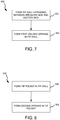
- FIG. 7 illustrates a method 500 of making a turbine blade, in accordance with an illustrative non-claimed example.
- Method 500 may comprise forming a tip wall extending from a pressure side of the turbine blade to a suction side of the turbine blade (step 502), and forming a first opening in the tip wall (step 504).
- the first opening comprises a first dimension and a second dimension less than the first dimension.
- the first dimension is oriented in a direction extending from a leading edge of the turbine blade to a trailing edge of the turbine blade.
- step 502 includes forming tip wall 154 extending from pressure side 150 to suction side 152 of blade 100.
- Step 504 comprises forming a first opening 200a in tip wall 154.
- First opening 200a comprises first dimension D1 and second dimension D2.
- Dimension D1 is oriented in a direction extending from leading edge 156 to trailing edge 158.
- method 500 further comprises forming a tip pocket in the tip wall (step 506), and forming a second opening in the tip pocket (step 508).
- Step 508 includes forming opening 360 in tip pocket 310.
Landscapes
- Engineering & Computer Science (AREA)
- Mechanical Engineering (AREA)
- General Engineering & Computer Science (AREA)
- Architecture (AREA)
- Turbine Rotor Nozzle Sealing (AREA)
Claims (8)
- Aube de turbine (100) pour un moteur à turbine à gaz (20), l'aube de turbine (100) comportant
une paroi côté pression (150) ;
une paroi côté aspiration (152) opposée à la paroi côté pression ;
une paroi d'extrémité (154) s'étendant entre la paroi côté pression (150) et la paroi côté aspiration (152) et comportant une première ouverture (200a) et une seconde ouverture (200b), dans laquelle une première dimension (D1) de la première ouverture est supérieure à une seconde dimension (D2) de la première ouverture, et dans laquelle la première dimension (D1) est orientée dans une direction s'étendant depuis un bord d'attaque (156) de l'aube de turbine (100) vers un bord de fuite (158) de l'aube de turbine ; et
une poche d'extrémité (310) formée dans la paroi d'extrémité (154) ;
caractérisée en ce que la seconde ouverture (200b) est située dans la poche d'extrémité (310) et la première ouverture (200a) est située à l'extérieur de la poche d'extrémité ;
en ce qu'une zone transversale de la première ouverture (200a) est constante à travers la paroi d'extrémité (154) ; et
en ce qu'une première zone de surface de la première ouverture (200a) est supérieure à une seconde zone de surface de la seconde ouverture (200b), et la première ouverture est formée dans une partie plus épaisse de la paroi d'extrémité (154) par rapport à la seconde ouverture. - Aube de turbine selon la revendication 1, dans laquelle la première ouverture (200a) comporte :une première extrémité semi-circulaire (202) ayant un premier rayon (R1) ;une seconde extrémité semi-circulaire (204) opposée à la première extrémité semi-circulaire ;une première paroi latérale (206) s'étendant depuis la première extrémité semi-circulaire vers la seconde extrémité semi-circulaire ; etune seconde paroi latérale (208) parallèle à la première paroi latérale (206) et s'étendant depuis la première extrémité semi-circulaire vers la seconde extrémité semi-circulaire.
- Aube de turbine selon la revendication 2, dans laquelle un rapport d'une longueur de la première paroi latérale (206) au premier rayon (R1) est compris entre 1:1 et 28:1.
- Aube de turbine selon la revendication 1, 2 ou 3, dans laquelle une première dimension (D1) de la seconde ouverture (200b) est supérieure à une seconde dimension (D2) de la seconde ouverture, la première dimension (D1) étant orientée dans une direction s'étendant depuis le bord d'attaque (156) de l'aube de turbine (100) vers le bord de fuite (158) de l'aube de turbine, et dans laquelle un rapport de la première dimension (D1) de la première ouverture (200a) à la seconde dimension (D2) de la première ouverture est supérieur à un rapport de la première dimension (D1) de la seconde ouverture (200b) à la seconde dimension (D2) de la seconde ouverture ; et
dans laquelle la première ouverture (200a) est située plus près du bord d'attaque (156) de l'aube de turbine (100) par rapport à la seconde ouverture (200b) et/ou dans laquelle la première ouverture (200a) est située plus près de la paroi côté pression (150) de l'aube de turbine (100) par rapport à la seconde ouverture (200b). - Moteur à turbine à gaz (20), comportant :une turbine comportant un ensemble rotor de turbine (130), l'ensemble rotor de turbine comportant :un disque de turbine (134), etl'aube de turbine (100) selon l'une quelconque des revendications 1 à 4 couplée au disque de turbine ; etun joint d'étanchéité à l'air extérieur d'aube (BOAS) (120) disposé autour de l'ensemble rotor de turbine (130).
- Moteur à turbine à gaz selon la revendication 5,
dans lequel la première ouverture (200a) dirige un écoulement d'air depuis l'aube de turbine (100) vers le BOAS (120). - Moteur à turbine à gaz selon la revendication 5 ou 6, dans lequel un rapport de la première dimension (D1) de la première ouverture (200a) à la seconde dimension (D2) de la première ouverture est compris entre 1,5:1 et 15:1.
- Procédé de fabrication d'une aube de turbine (100), comportant :la formation d'une paroi d'extrémité (154) s'étendant entre un côté pression (150) de l'aube de turbine et un côté aspiration (152) de l'aube de turbine ;la formation d'une poche d'extrémité (310) dans la paroi d'extrémité (154) ;la formation d'une première ouverture (200a) dans la paroi d'extrémité (154) à l'extérieur de la poche d'extrémité, la première ouverture comportant une première dimension (D1) et une seconde dimension (D2) inférieure à la première dimension, dans lequel la première dimension (D1) est orientée dans une direction s'étendant depuis un bord d'attaque (156) de l'aube de turbine (100) vers un bord de fuite (158) de l'aube de turbine, et dans lequel une zone transversale de la première ouverture (200a) est constante à travers la paroi d'extrémité (154) ; etla formation d'une seconde ouverture (200b) dans la paroi d'extrémité (154) dans la poche d'extrémité, dans lequel une première zone de surface de la première ouverture (200a) est supérieure à une seconde zone de surface de la seconde ouverture (200b), et dans lequel la première ouverture (200a) est formée dans une partie plus épaisse de la paroi d'extrémité (154) par rapport à la seconde ouverture (200b).
Applications Claiming Priority (1)
| Application Number | Priority Date | Filing Date | Title |
|---|---|---|---|
| US15/613,923 US10533428B2 (en) | 2017-06-05 | 2017-06-05 | Oblong purge holes |
Publications (2)
| Publication Number | Publication Date |
|---|---|
| EP3412870A1 EP3412870A1 (fr) | 2018-12-12 |
| EP3412870B1 true EP3412870B1 (fr) | 2021-04-07 |
Family
ID=62386026
Family Applications (1)
| Application Number | Title | Priority Date | Filing Date |
|---|---|---|---|
| EP18174121.6A Active EP3412870B1 (fr) | 2017-06-05 | 2018-05-24 | Extrémité d'aube de turbine comportant des trous de purge oblongues |
Country Status (2)
| Country | Link |
|---|---|
| US (1) | US10533428B2 (fr) |
| EP (1) | EP3412870B1 (fr) |
Families Citing this family (5)
| Publication number | Priority date | Publication date | Assignee | Title |
|---|---|---|---|---|
| CN109356884A (zh) * | 2018-12-21 | 2019-02-19 | 大连海事大学 | 一种具有仿生顶室的压气机动叶 |
| US11149550B2 (en) | 2019-02-07 | 2021-10-19 | Raytheon Technologies Corporation | Blade neck transition |
| US10871074B2 (en) * | 2019-02-28 | 2020-12-22 | Raytheon Technologies Corporation | Blade/vane cooling passages |
| US11053803B2 (en) * | 2019-06-26 | 2021-07-06 | Raytheon Technologies Corporation | Airfoils and core assemblies for gas turbine engines and methods of manufacture |
| IT202100000296A1 (it) * | 2021-01-08 | 2022-07-08 | Gen Electric | Motore a turbine con paletta avente un insieme di fossette |
Family Cites Families (16)
| Publication number | Priority date | Publication date | Assignee | Title |
|---|---|---|---|---|
| GB827289A (en) | 1955-10-26 | 1960-02-03 | Wiggin & Co Ltd Henry | Improvements relating to hollow turbine or compressor blades |
| US3045328A (en) | 1956-05-08 | 1962-07-24 | Int Nickel Co | Manufacture of hollow turbine blades |
| US4606701A (en) * | 1981-09-02 | 1986-08-19 | Westinghouse Electric Corp. | Tip structure for a cooled turbine rotor blade |
| US5864949A (en) * | 1992-10-27 | 1999-02-02 | United Technologies Corporation | Tip seal and anti-contamination for turbine blades |
| US5927946A (en) * | 1997-09-29 | 1999-07-27 | General Electric Company | Turbine blade having recuperative trailing edge tip cooling |
| US6190129B1 (en) * | 1998-12-21 | 2001-02-20 | General Electric Company | Tapered tip-rib turbine blade |
| US20030021684A1 (en) | 2001-07-24 | 2003-01-30 | Downs James P. | Turbine blade tip cooling construction |
| US6652235B1 (en) * | 2002-05-31 | 2003-11-25 | General Electric Company | Method and apparatus for reducing turbine blade tip region temperatures |
| US7597539B1 (en) | 2006-09-27 | 2009-10-06 | Florida Turbine Technologies, Inc. | Turbine blade with vortex cooled end tip rail |
| US8469666B1 (en) * | 2008-08-21 | 2013-06-25 | Florida Turbine Technologies, Inc. | Turbine blade tip portion with trenched cooling holes |
| US8186965B2 (en) * | 2009-05-27 | 2012-05-29 | General Electric Company | Recovery tip turbine blade |
| US9085988B2 (en) | 2010-12-24 | 2015-07-21 | Rolls-Royce North American Technologies, Inc. | Gas turbine engine flow path member |
| US20160102561A1 (en) | 2014-10-14 | 2016-04-14 | United Technologies Corporation | Gas turbine engine turbine blade tip cooling |
| US9995147B2 (en) | 2015-02-11 | 2018-06-12 | United Technologies Corporation | Blade tip cooling arrangement |
| US10107108B2 (en) * | 2015-04-29 | 2018-10-23 | General Electric Company | Rotor blade having a flared tip |
| US20170058680A1 (en) * | 2015-09-02 | 2017-03-02 | General Electric Company | Configurations for turbine rotor blade tips |
-
2017
- 2017-06-05 US US15/613,923 patent/US10533428B2/en active Active
-
2018
- 2018-05-24 EP EP18174121.6A patent/EP3412870B1/fr active Active
Non-Patent Citations (1)
| Title |
|---|
| None * |
Also Published As
| Publication number | Publication date |
|---|---|
| US20180347379A1 (en) | 2018-12-06 |
| EP3412870A1 (fr) | 2018-12-12 |
| US10533428B2 (en) | 2020-01-14 |
Similar Documents
| Publication | Publication Date | Title |
|---|---|---|
| EP3650657B1 (fr) | Ensemble d'étanchéité avec plaque d'étanchéité d'impact | |
| EP2954168B1 (fr) | Pièce de turbine à gaz comportant un turbulateur incurvé | |
| US11624322B2 (en) | Hourglass airfoil cooling configuration | |
| EP3091184B1 (fr) | Refroidissement du bord d'attaque d'une aube de turbine | |
| EP3477058B1 (fr) | Circuit de refroidissement de profil aérodynamique | |
| EP2877709B1 (fr) | Joint d'étanchéité vis-à-vis de l'air externe de pale pour une turbine à gaz | |
| EP3412870A1 (fr) | Extrémité d'aube de turbine comportant des trous de purge oblongues | |
| US9394915B2 (en) | Seal land for static structure of a gas turbine engine | |
| US10794194B2 (en) | Staggered core printout | |
| US20150354372A1 (en) | Gas turbine engine component with angled aperture impingement | |
| EP3054093B1 (fr) | Agencement de nervures décalées | |
| EP3181828B1 (fr) | Joint d'air extérieur d'aube doté de bouclier d'air intégré | |
| EP3477053B1 (fr) | Circuit de refroidissement de profil aérodynamique d'une turbine á gaz et procédé de fabrication | |
| EP3957824B1 (fr) | Dispositif tandem de disque de rotor et moteur à turbine à gaz associé | |
| US12065945B2 (en) | Internally cooled turbine blade | |
| EP3575552B1 (fr) | Canal en u optimisé coriolis avec refroidissement de la plateforme | |
| WO2014105547A1 (fr) | Élément de turbine à gaz présentant une ouverture de réduction côté aspiration |
Legal Events
| Date | Code | Title | Description |
|---|---|---|---|
| PUAI | Public reference made under article 153(3) epc to a published international application that has entered the european phase |
Free format text: ORIGINAL CODE: 0009012 |
|
| STAA | Information on the status of an ep patent application or granted ep patent |
Free format text: STATUS: THE APPLICATION HAS BEEN PUBLISHED |
|
| AK | Designated contracting states |
Kind code of ref document: A1 Designated state(s): AL AT BE BG CH CY CZ DE DK EE ES FI FR GB GR HR HU IE IS IT LI LT LU LV MC MK MT NL NO PL PT RO RS SE SI SK SM TR |
|
| AX | Request for extension of the european patent |
Extension state: BA ME |
|
| STAA | Information on the status of an ep patent application or granted ep patent |
Free format text: STATUS: REQUEST FOR EXAMINATION WAS MADE |
|
| 17P | Request for examination filed |
Effective date: 20190612 |
|
| RBV | Designated contracting states (corrected) |
Designated state(s): AL AT BE BG CH CY CZ DE DK EE ES FI FR GB GR HR HU IE IS IT LI LT LU LV MC MK MT NL NO PL PT RO RS SE SI SK SM TR |
|
| STAA | Information on the status of an ep patent application or granted ep patent |
Free format text: STATUS: EXAMINATION IS IN PROGRESS |
|
| 17Q | First examination report despatched |
Effective date: 20200131 |
|
| GRAP | Despatch of communication of intention to grant a patent |
Free format text: ORIGINAL CODE: EPIDOSNIGR1 |
|
| STAA | Information on the status of an ep patent application or granted ep patent |
Free format text: STATUS: GRANT OF PATENT IS INTENDED |
|
| INTG | Intention to grant announced |
Effective date: 20200706 |
|
| GRAJ | Information related to disapproval of communication of intention to grant by the applicant or resumption of examination proceedings by the epo deleted |
Free format text: ORIGINAL CODE: EPIDOSDIGR1 |
|
| STAA | Information on the status of an ep patent application or granted ep patent |
Free format text: STATUS: EXAMINATION IS IN PROGRESS |
|
| GRAP | Despatch of communication of intention to grant a patent |
Free format text: ORIGINAL CODE: EPIDOSNIGR1 |
|
| STAA | Information on the status of an ep patent application or granted ep patent |
Free format text: STATUS: GRANT OF PATENT IS INTENDED |
|
| INTC | Intention to grant announced (deleted) | ||
| INTG | Intention to grant announced |
Effective date: 20201209 |
|
| GRAS | Grant fee paid |
Free format text: ORIGINAL CODE: EPIDOSNIGR3 |
|
| GRAA | (expected) grant |
Free format text: ORIGINAL CODE: 0009210 |
|
| STAA | Information on the status of an ep patent application or granted ep patent |
Free format text: STATUS: THE PATENT HAS BEEN GRANTED |
|
| RAP1 | Party data changed (applicant data changed or rights of an application transferred) |
Owner name: RAYTHEON TECHNOLOGIES CORPORATION |
|
| AK | Designated contracting states |
Kind code of ref document: B1 Designated state(s): AL AT BE BG CH CY CZ DE DK EE ES FI FR GB GR HR HU IE IS IT LI LT LU LV MC MK MT NL NO PL PT RO RS SE SI SK SM TR |
|
| REG | Reference to a national code |
Ref country code: GB Ref legal event code: FG4D |
|
| REG | Reference to a national code |
Ref country code: AT Ref legal event code: REF Ref document number: 1379931 Country of ref document: AT Kind code of ref document: T Effective date: 20210415 Ref country code: CH Ref legal event code: EP |
|
| REG | Reference to a national code |
Ref country code: DE Ref legal event code: R096 Ref document number: 602018015000 Country of ref document: DE |
|
| REG | Reference to a national code |
Ref country code: IE Ref legal event code: FG4D |
|
| REG | Reference to a national code |
Ref country code: LT Ref legal event code: MG9D |
|
| REG | Reference to a national code |
Ref country code: NL Ref legal event code: MP Effective date: 20210407 Ref country code: AT Ref legal event code: MK05 Ref document number: 1379931 Country of ref document: AT Kind code of ref document: T Effective date: 20210407 |
|
| PG25 | Lapsed in a contracting state [announced via postgrant information from national office to epo] |
Ref country code: FI Free format text: LAPSE BECAUSE OF FAILURE TO SUBMIT A TRANSLATION OF THE DESCRIPTION OR TO PAY THE FEE WITHIN THE PRESCRIBED TIME-LIMIT Effective date: 20210407 Ref country code: HR Free format text: LAPSE BECAUSE OF FAILURE TO SUBMIT A TRANSLATION OF THE DESCRIPTION OR TO PAY THE FEE WITHIN THE PRESCRIBED TIME-LIMIT Effective date: 20210407 Ref country code: LT Free format text: LAPSE BECAUSE OF FAILURE TO SUBMIT A TRANSLATION OF THE DESCRIPTION OR TO PAY THE FEE WITHIN THE PRESCRIBED TIME-LIMIT Effective date: 20210407 Ref country code: NL Free format text: LAPSE BECAUSE OF FAILURE TO SUBMIT A TRANSLATION OF THE DESCRIPTION OR TO PAY THE FEE WITHIN THE PRESCRIBED TIME-LIMIT Effective date: 20210407 Ref country code: BG Free format text: LAPSE BECAUSE OF FAILURE TO SUBMIT A TRANSLATION OF THE DESCRIPTION OR TO PAY THE FEE WITHIN THE PRESCRIBED TIME-LIMIT Effective date: 20210707 Ref country code: AT Free format text: LAPSE BECAUSE OF FAILURE TO SUBMIT A TRANSLATION OF THE DESCRIPTION OR TO PAY THE FEE WITHIN THE PRESCRIBED TIME-LIMIT Effective date: 20210407 |
|
| PG25 | Lapsed in a contracting state [announced via postgrant information from national office to epo] |
Ref country code: IS Free format text: LAPSE BECAUSE OF FAILURE TO SUBMIT A TRANSLATION OF THE DESCRIPTION OR TO PAY THE FEE WITHIN THE PRESCRIBED TIME-LIMIT Effective date: 20210807 Ref country code: GR Free format text: LAPSE BECAUSE OF FAILURE TO SUBMIT A TRANSLATION OF THE DESCRIPTION OR TO PAY THE FEE WITHIN THE PRESCRIBED TIME-LIMIT Effective date: 20210708 Ref country code: PL Free format text: LAPSE BECAUSE OF FAILURE TO SUBMIT A TRANSLATION OF THE DESCRIPTION OR TO PAY THE FEE WITHIN THE PRESCRIBED TIME-LIMIT Effective date: 20210407 Ref country code: LV Free format text: LAPSE BECAUSE OF FAILURE TO SUBMIT A TRANSLATION OF THE DESCRIPTION OR TO PAY THE FEE WITHIN THE PRESCRIBED TIME-LIMIT Effective date: 20210407 Ref country code: NO Free format text: LAPSE BECAUSE OF FAILURE TO SUBMIT A TRANSLATION OF THE DESCRIPTION OR TO PAY THE FEE WITHIN THE PRESCRIBED TIME-LIMIT Effective date: 20210707 Ref country code: PT Free format text: LAPSE BECAUSE OF FAILURE TO SUBMIT A TRANSLATION OF THE DESCRIPTION OR TO PAY THE FEE WITHIN THE PRESCRIBED TIME-LIMIT Effective date: 20210809 Ref country code: SE Free format text: LAPSE BECAUSE OF FAILURE TO SUBMIT A TRANSLATION OF THE DESCRIPTION OR TO PAY THE FEE WITHIN THE PRESCRIBED TIME-LIMIT Effective date: 20210407 Ref country code: RS Free format text: LAPSE BECAUSE OF FAILURE TO SUBMIT A TRANSLATION OF THE DESCRIPTION OR TO PAY THE FEE WITHIN THE PRESCRIBED TIME-LIMIT Effective date: 20210407 |
|
| REG | Reference to a national code |
Ref country code: CH Ref legal event code: PL |
|
| REG | Reference to a national code |
Ref country code: DE Ref legal event code: R097 Ref document number: 602018015000 Country of ref document: DE |
|
| PG25 | Lapsed in a contracting state [announced via postgrant information from national office to epo] |
Ref country code: CH Free format text: LAPSE BECAUSE OF NON-PAYMENT OF DUE FEES Effective date: 20210531 Ref country code: CZ Free format text: LAPSE BECAUSE OF FAILURE TO SUBMIT A TRANSLATION OF THE DESCRIPTION OR TO PAY THE FEE WITHIN THE PRESCRIBED TIME-LIMIT Effective date: 20210407 Ref country code: DK Free format text: LAPSE BECAUSE OF FAILURE TO SUBMIT A TRANSLATION OF THE DESCRIPTION OR TO PAY THE FEE WITHIN THE PRESCRIBED TIME-LIMIT Effective date: 20210407 Ref country code: LU Free format text: LAPSE BECAUSE OF NON-PAYMENT OF DUE FEES Effective date: 20210524 Ref country code: MC Free format text: LAPSE BECAUSE OF FAILURE TO SUBMIT A TRANSLATION OF THE DESCRIPTION OR TO PAY THE FEE WITHIN THE PRESCRIBED TIME-LIMIT Effective date: 20210407 Ref country code: LI Free format text: LAPSE BECAUSE OF NON-PAYMENT OF DUE FEES Effective date: 20210531 Ref country code: RO Free format text: LAPSE BECAUSE OF FAILURE TO SUBMIT A TRANSLATION OF THE DESCRIPTION OR TO PAY THE FEE WITHIN THE PRESCRIBED TIME-LIMIT Effective date: 20210407 Ref country code: SM Free format text: LAPSE BECAUSE OF FAILURE TO SUBMIT A TRANSLATION OF THE DESCRIPTION OR TO PAY THE FEE WITHIN THE PRESCRIBED TIME-LIMIT Effective date: 20210407 Ref country code: SK Free format text: LAPSE BECAUSE OF FAILURE TO SUBMIT A TRANSLATION OF THE DESCRIPTION OR TO PAY THE FEE WITHIN THE PRESCRIBED TIME-LIMIT Effective date: 20210407 Ref country code: ES Free format text: LAPSE BECAUSE OF FAILURE TO SUBMIT A TRANSLATION OF THE DESCRIPTION OR TO PAY THE FEE WITHIN THE PRESCRIBED TIME-LIMIT Effective date: 20210407 Ref country code: EE Free format text: LAPSE BECAUSE OF FAILURE TO SUBMIT A TRANSLATION OF THE DESCRIPTION OR TO PAY THE FEE WITHIN THE PRESCRIBED TIME-LIMIT Effective date: 20210407 |
|
| REG | Reference to a national code |
Ref country code: BE Ref legal event code: MM Effective date: 20210531 |
|
| PLBE | No opposition filed within time limit |
Free format text: ORIGINAL CODE: 0009261 |
|
| STAA | Information on the status of an ep patent application or granted ep patent |
Free format text: STATUS: NO OPPOSITION FILED WITHIN TIME LIMIT |
|
| 26N | No opposition filed |
Effective date: 20220110 |
|
| PG25 | Lapsed in a contracting state [announced via postgrant information from national office to epo] |
Ref country code: IE Free format text: LAPSE BECAUSE OF NON-PAYMENT OF DUE FEES Effective date: 20210524 |
|
| PG25 | Lapsed in a contracting state [announced via postgrant information from national office to epo] |
Ref country code: IS Free format text: LAPSE BECAUSE OF FAILURE TO SUBMIT A TRANSLATION OF THE DESCRIPTION OR TO PAY THE FEE WITHIN THE PRESCRIBED TIME-LIMIT Effective date: 20210807 Ref country code: AL Free format text: LAPSE BECAUSE OF FAILURE TO SUBMIT A TRANSLATION OF THE DESCRIPTION OR TO PAY THE FEE WITHIN THE PRESCRIBED TIME-LIMIT Effective date: 20210407 |
|
| PG25 | Lapsed in a contracting state [announced via postgrant information from national office to epo] |
Ref country code: IT Free format text: LAPSE BECAUSE OF FAILURE TO SUBMIT A TRANSLATION OF THE DESCRIPTION OR TO PAY THE FEE WITHIN THE PRESCRIBED TIME-LIMIT Effective date: 20210407 Ref country code: BE Free format text: LAPSE BECAUSE OF NON-PAYMENT OF DUE FEES Effective date: 20210531 |
|
| P01 | Opt-out of the competence of the unified patent court (upc) registered |
Effective date: 20230521 |
|
| PG25 | Lapsed in a contracting state [announced via postgrant information from national office to epo] |
Ref country code: CY Free format text: LAPSE BECAUSE OF FAILURE TO SUBMIT A TRANSLATION OF THE DESCRIPTION OR TO PAY THE FEE WITHIN THE PRESCRIBED TIME-LIMIT Effective date: 20210407 |
|
| PG25 | Lapsed in a contracting state [announced via postgrant information from national office to epo] |
Ref country code: HU Free format text: LAPSE BECAUSE OF FAILURE TO SUBMIT A TRANSLATION OF THE DESCRIPTION OR TO PAY THE FEE WITHIN THE PRESCRIBED TIME-LIMIT; INVALID AB INITIO Effective date: 20180524 |
|
| PG25 | Lapsed in a contracting state [announced via postgrant information from national office to epo] |
Ref country code: MK Free format text: LAPSE BECAUSE OF FAILURE TO SUBMIT A TRANSLATION OF THE DESCRIPTION OR TO PAY THE FEE WITHIN THE PRESCRIBED TIME-LIMIT Effective date: 20210407 |
|
| PG25 | Lapsed in a contracting state [announced via postgrant information from national office to epo] |
Ref country code: MT Free format text: LAPSE BECAUSE OF FAILURE TO SUBMIT A TRANSLATION OF THE DESCRIPTION OR TO PAY THE FEE WITHIN THE PRESCRIBED TIME-LIMIT Effective date: 20210407 |
|
| PGFP | Annual fee paid to national office [announced via postgrant information from national office to epo] |
Ref country code: DE Payment date: 20250423 Year of fee payment: 8 |
|
| PGFP | Annual fee paid to national office [announced via postgrant information from national office to epo] |
Ref country code: GB Payment date: 20250423 Year of fee payment: 8 |
|
| PGFP | Annual fee paid to national office [announced via postgrant information from national office to epo] |
Ref country code: FR Payment date: 20250423 Year of fee payment: 8 |
|
| REG | Reference to a national code |
Ref country code: DE Ref legal event code: R081 Ref document number: 602018015000 Country of ref document: DE Owner name: RTX CORPORATION (N.D.GES.D. STAATES DELAWARE),, US Free format text: FORMER OWNER: RAYTHEON TECHNOLOGIES CORPORATION, FARMINGTON, CT, US |
|
| PG25 | Lapsed in a contracting state [announced via postgrant information from national office to epo] |
Ref country code: TR Free format text: LAPSE BECAUSE OF FAILURE TO SUBMIT A TRANSLATION OF THE DESCRIPTION OR TO PAY THE FEE WITHIN THE PRESCRIBED TIME-LIMIT Effective date: 20210407 |