EP3412879A1 - Dispositif de post-traitement de gaz d'échappement d'un moteur à combustion interne - Google Patents
Dispositif de post-traitement de gaz d'échappement d'un moteur à combustion interne Download PDFInfo
- Publication number
- EP3412879A1 EP3412879A1 EP18170326.5A EP18170326A EP3412879A1 EP 3412879 A1 EP3412879 A1 EP 3412879A1 EP 18170326 A EP18170326 A EP 18170326A EP 3412879 A1 EP3412879 A1 EP 3412879A1
- Authority
- EP
- European Patent Office
- Prior art keywords
- housing shell
- leg
- housing
- exhaust
- centering
- Prior art date
- Legal status (The legal status is an assumption and is not a legal conclusion. Google has not performed a legal analysis and makes no representation as to the accuracy of the status listed.)
- Granted
Links
Images


Classifications
-
- F—MECHANICAL ENGINEERING; LIGHTING; HEATING; WEAPONS; BLASTING
- F01—MACHINES OR ENGINES IN GENERAL; ENGINE PLANTS IN GENERAL; STEAM ENGINES
- F01N—GAS-FLOW SILENCERS OR EXHAUST APPARATUS FOR MACHINES OR ENGINES IN GENERAL; GAS-FLOW SILENCERS OR EXHAUST APPARATUS FOR INTERNAL-COMBUSTION ENGINES
- F01N3/00—Exhaust or silencing apparatus having means for purifying, rendering innocuous, or otherwise treating exhaust
- F01N3/02—Exhaust or silencing apparatus having means for purifying, rendering innocuous, or otherwise treating exhaust for cooling, or for removing solid constituents of, exhaust
-
- F—MECHANICAL ENGINEERING; LIGHTING; HEATING; WEAPONS; BLASTING
- F01—MACHINES OR ENGINES IN GENERAL; ENGINE PLANTS IN GENERAL; STEAM ENGINES
- F01N—GAS-FLOW SILENCERS OR EXHAUST APPARATUS FOR MACHINES OR ENGINES IN GENERAL; GAS-FLOW SILENCERS OR EXHAUST APPARATUS FOR INTERNAL-COMBUSTION ENGINES
- F01N13/00—Exhaust or silencing apparatus characterised by constructional features
- F01N13/009—Exhaust or silencing apparatus characterised by constructional features having two or more separate purifying devices arranged in series
- F01N13/0097—Exhaust or silencing apparatus characterised by constructional features having two or more separate purifying devices arranged in series the purifying devices are arranged in a single housing
-
- F—MECHANICAL ENGINEERING; LIGHTING; HEATING; WEAPONS; BLASTING
- F01—MACHINES OR ENGINES IN GENERAL; ENGINE PLANTS IN GENERAL; STEAM ENGINES
- F01N—GAS-FLOW SILENCERS OR EXHAUST APPARATUS FOR MACHINES OR ENGINES IN GENERAL; GAS-FLOW SILENCERS OR EXHAUST APPARATUS FOR INTERNAL-COMBUSTION ENGINES
- F01N13/00—Exhaust or silencing apparatus characterised by constructional features
- F01N13/18—Construction facilitating manufacture, assembly, or disassembly
- F01N13/1838—Construction facilitating manufacture, assembly, or disassembly characterised by the type of connection between parts of exhaust or silencing apparatus, e.g. between housing and tubes, between tubes and baffles
-
- F—MECHANICAL ENGINEERING; LIGHTING; HEATING; WEAPONS; BLASTING
- F01—MACHINES OR ENGINES IN GENERAL; ENGINE PLANTS IN GENERAL; STEAM ENGINES
- F01N—GAS-FLOW SILENCERS OR EXHAUST APPARATUS FOR MACHINES OR ENGINES IN GENERAL; GAS-FLOW SILENCERS OR EXHAUST APPARATUS FOR INTERNAL-COMBUSTION ENGINES
- F01N13/00—Exhaust or silencing apparatus characterised by constructional features
- F01N13/18—Construction facilitating manufacture, assembly, or disassembly
- F01N13/1888—Construction facilitating manufacture, assembly, or disassembly the housing of the assembly consisting of two or more parts, e.g. two half-shells
-
- F—MECHANICAL ENGINEERING; LIGHTING; HEATING; WEAPONS; BLASTING
- F16—ENGINEERING ELEMENTS AND UNITS; GENERAL MEASURES FOR PRODUCING AND MAINTAINING EFFECTIVE FUNCTIONING OF MACHINES OR INSTALLATIONS; THERMAL INSULATION IN GENERAL
- F16L—PIPES; JOINTS OR FITTINGS FOR PIPES; SUPPORTS FOR PIPES, CABLES OR PROTECTIVE TUBING; MEANS FOR THERMAL INSULATION IN GENERAL
- F16L23/00—Flanged joints
- F16L23/04—Flanged joints the flanges being connected by members tensioned in the radial plane
-
- F—MECHANICAL ENGINEERING; LIGHTING; HEATING; WEAPONS; BLASTING
- F01—MACHINES OR ENGINES IN GENERAL; ENGINE PLANTS IN GENERAL; STEAM ENGINES
- F01N—GAS-FLOW SILENCERS OR EXHAUST APPARATUS FOR MACHINES OR ENGINES IN GENERAL; GAS-FLOW SILENCERS OR EXHAUST APPARATUS FOR INTERNAL-COMBUSTION ENGINES
- F01N2450/00—Methods or apparatus for fitting, inserting or repairing different elements
- F01N2450/18—Methods or apparatus for fitting, inserting or repairing different elements by using quick-active type locking mechanisms, e.g. clips
-
- F—MECHANICAL ENGINEERING; LIGHTING; HEATING; WEAPONS; BLASTING
- F01—MACHINES OR ENGINES IN GENERAL; ENGINE PLANTS IN GENERAL; STEAM ENGINES
- F01N—GAS-FLOW SILENCERS OR EXHAUST APPARATUS FOR MACHINES OR ENGINES IN GENERAL; GAS-FLOW SILENCERS OR EXHAUST APPARATUS FOR INTERNAL-COMBUSTION ENGINES
- F01N2450/00—Methods or apparatus for fitting, inserting or repairing different elements
- F01N2450/30—Removable or rechangeable blocks or cartridges, e.g. for filters
-
- Y—GENERAL TAGGING OF NEW TECHNOLOGICAL DEVELOPMENTS; GENERAL TAGGING OF CROSS-SECTIONAL TECHNOLOGIES SPANNING OVER SEVERAL SECTIONS OF THE IPC; TECHNICAL SUBJECTS COVERED BY FORMER USPC CROSS-REFERENCE ART COLLECTIONS [XRACs] AND DIGESTS
- Y02—TECHNOLOGIES OR APPLICATIONS FOR MITIGATION OR ADAPTATION AGAINST CLIMATE CHANGE
- Y02A—TECHNOLOGIES FOR ADAPTATION TO CLIMATE CHANGE
- Y02A50/00—TECHNOLOGIES FOR ADAPTATION TO CLIMATE CHANGE in human health protection, e.g. against extreme weather
- Y02A50/20—Air quality improvement or preservation, e.g. vehicle emission control or emission reduction by using catalytic converters
-
- Y—GENERAL TAGGING OF NEW TECHNOLOGICAL DEVELOPMENTS; GENERAL TAGGING OF CROSS-SECTIONAL TECHNOLOGIES SPANNING OVER SEVERAL SECTIONS OF THE IPC; TECHNICAL SUBJECTS COVERED BY FORMER USPC CROSS-REFERENCE ART COLLECTIONS [XRACs] AND DIGESTS
- Y02—TECHNOLOGIES OR APPLICATIONS FOR MITIGATION OR ADAPTATION AGAINST CLIMATE CHANGE
- Y02T—CLIMATE CHANGE MITIGATION TECHNOLOGIES RELATED TO TRANSPORTATION
- Y02T10/00—Road transport of goods or passengers
- Y02T10/10—Internal combustion engine [ICE] based vehicles
- Y02T10/12—Improving ICE efficiencies
Definitions
- the invention is based on an exhaust gas aftertreatment device of an internal combustion engine of a motor vehicle, which at least partially frees an exhaust gas flow introduced via an inlet opening from pollutants and then via an outlet opening into the atmosphere and which has a housing with a plurality of housing shells, according to the preamble of claim 1.
- the invention also relates to a motor vehicle with an internal combustion engine and with at least one such exhaust gas treatment device according to claim 22.
- Housing shells such exhaust aftertreatment device usually live muffler, soot filter and / or catalysts such as an oxidation catalyst and / or a reduction catalyst.
- the vibration load of the exhaust aftertreatment device plays an important role in operation, since such vibrations can lead to deformation loads and thus to premature fatigue, especially in the housing of the exhaust aftertreatment device.
- the invention is based on the object, an exhaust aftertreatment device of the type mentioned in such a way that it has a longer life. Likewise, a motor vehicle to be provided with such an exhaust aftertreatment device.
- the invention is based on an exhaust gas aftertreatment device of an internal combustion engine of a motor vehicle, which at least partially frees an exhaust gas flow introduced via an inlet opening from pollutants and then via an outlet opening into the atmosphere and which has a housing with a plurality of housing shells, wherein at least a first of the housing shells Housing shell is connected to at least one second housing shell by at least one releasable connection, the releasable connection comprises at least one centering ring, via which the housing shells in a Mounting plane contact each other indirectly, the at least one centering ring is a separate from the housing shells separate component having at least one centering an inner Zentrierkragen, one ends of the housing shells intermediate central portion and an outer centering collar, the inner Zentrierkragen on a radially inner peripheral surface of the first housing shell and the outer centering collar is provided on a radially outer circumferential surface of the second housing shell for abutment, or the inner centering collar is provided on a radially inner peripheral surface of
- a housing shell is understood to mean any housing component of the housing of the exhaust aftertreatment device which at least partially houses or absorbs any assembly or component of the exhaust aftertreatment device that affects the quality and / or quantity of the exhaust stream, particularly with respect to pollutants therein and / or by which any other function influencing the exhaust gas flow is exerted, eg a directional control of the exhaust stream (swirl generation, flow deflection) or mixes it with additives such as urea solution or sound attenuation of the sound generated by the exhaust stream.
- the first housing shell and the second housing shell may be formed integrally or also in several parts.
- the at least one centering ring is a separate component from the housing shells, requires a simple construction and assembly, since the centering ring does not have to be connected to a housing shell, for example by welding, but only by inserting the inner centering collar can be mounted in a housing shell and transverse plug of another housing shell.
- the first housing shell and the second housing shell are centered by means of at least one centering against each other and, for example, with clamping means connected to each other, wherein the centering allows a relative movement of the housing shells in the mounting plane of the housing shells.
- the peripheral recess or peripheral boundary of the outer centering allows the housing shells for mounting and dismounting of the housing or for replacing the first housing shell against a new first housing shell along the mounting plane and in particular without displacement perpendicular to the mounting plane can be moved relative to each other, for example by a End of a housing shell, on whose outer peripheral surface an outer centering collar abuts through the peripheral recess is pulled along along the mounting plane.
- the circumferentially limited outer centering collar is sufficient to center the housing shells in the installed position against each other.
- the mounting plane is therefore defined as a plane along which or parallel to which the first housing shell and the second housing shell are movable relative to each other, even if the at least one centering ring is already mounted on the first housing shell and on the second housing shell. If then the ends of the housing shells are additionally overlapped by a clamping means, results in a relatively rigid connection of the housing shells.
- the invention provides that the second housing shell has a cross-sectionally U-shaped cross-section with two legs connecting a crosspiece, a first leg and a second leg.
- the two legs protrude, for example, vertically away from the ends of the crosspiece.
- the abutting surfaces and flow connections between the transverse web and the first leg and between the transverse web and the second leg preferably lie in a plane which is perpendicular to a central axis of the first housing shell.
- the first housing shell is held between the first and the second leg of the second housing shell by two releasable connections, namely a first releasable connection and a second detachable connection.
- first centering ring is then a part of the first releasable connection and the second centering ring is a part of the second detachable connection.
- the first centering ring and the second centering ring each have a circular cross-section, wherein the outer centering collar extends in each case to at most over half the circumference of the respective centering ring.
- the first housing shell also preferably has a cylindrical cross-section.
- the inner centering collar can extend over the entire circumference of the respective centering ring and, viewed in the circumferential direction, can be provided with circumferential gaps or be formed without circumferential gaps. Without circumferential gaps means that the inner centering collar rotates completely without interruption.
- the inner centering collar may be formed only in sections and in particular also have peripheral gaps.
- a seal is provided in each case between the middle section of a centering ring and an end of the first housing shell facing toward the middle section, and between the middle section of the centering ring and an end of the second housing shell facing the middle section.
- the first leg of the second housing shell may have a first connecting piece arranged perpendicularly to a first mounting plane and provided with at least one first flow opening and the second leg of the second housing shell having a second connecting piece arranged perpendicularly to a second mounting plane and provided with at least one second flow opening ,
- the two nozzles are, for example, each cylindrical with a circular cross-section and arranged coaxially with each other, with their flow openings facing each other.
- their free, each other For example, ends have an identical diameter. The diameter is at least in the region of the free ends of the nozzle, for example, identical to the diameter of the first end of the first housing shell and the second end of the first housing shell.
- the diameter in the region of the free end of the first nozzle could for example be different with respect to the diameter in the region of the free end of the second nozzle, in which case the diameter in the region of the first end of the first housing shell with respect to the diameter in the range the second end of the first housing shell is different in size, because the free end of the first nozzle is connected to the first end of the first housing shell and the free end of the second nozzle to the second end of the first housing shell.
- the first housing shell is preferably held at its two ends in relation to the two nozzles coaxially in the second housing shell.
- the two mounting planes are preferably parallel to each other.
- the central portions of the centering rings are preferably arranged perpendicular to the central axis of the nozzle or the first housing shell and in the mounting planes, while the inner centering collar and the outer centering collar, for example, cylindrical and coaxial with respect to the central axis.
- the first centering ring between a free end of the first nozzle and a first end of the first housing shell and the second centering ring between a second end of the first housing shell and a free end of the second nozzle of the second housing shell can then be arranged.
- the releasable connections may comprise two clamping means, of which a first clamping means the free end of the first nozzle and the first end of the first housing shell and a second clamping means the free end of the second nozzle and the second end of the first housing shell against each other clamps and thereby fixed on the one hand the position of the ends intermediate centering rings and on the other hand, the ends in each case connects to each other.
- the free end of the first nozzle, the first end of the first housing shell, the second end of the first housing shell and the free end of the second nozzle of the second housing shell each have at least one circle descriptive and outwardly projecting curl or curl.
- the middle section of a centering ring can then extend substantially in the assembly plane and contact these curls or curls indirectly or directly in the manner of a line.
- the provided with flanges or curls at the end housing shells are also combined with each other in an advantageous manner in the manner of a modular system with each other, because the contact surfaces are each formed identically and in each case a line contact is given.
- a centering ring also serves as a seal carrier.
- the preferably flat or straight middle sections of the centering rings can essentially run in the mounting planes and contact on both sides at least one flanging or curving line-like directly or indirectly via the seals. Due to the line contact in the contact area between the seals and the curls or flanges, a sealing edge forms, which seals better due to the relatively high pressure along the contact line as is the case for a flat contact.
- the formation of a sealing edge is particularly advantageous when using elastic seals, because due to the higher pressure in the sealing gap smaller clamping forces are sufficient.
- sealing elements can be used cheap, commercial molded gaskets such as flat gaskets.
- the crimps or curls can then contact the flat or straight central portion of a centering ring along a line and are simple and cheap way to produce by rolling. In addition, they are relatively insensitive to mechanical effects because of their high structural rigidity or dimensional stability. Furthermore, the position of the contact line is not important for the sealing function, so that the connection according to the invention is fault-tolerant. This is particularly advantageous in exhaust aftertreatment devices which, due to their production, have relatively large tolerances. In addition, because of the line contact an extremely small contact surface between the housing shells and the center portions of the centering rings is present, so that due to the reduced contact surface is less likely that the components stick together due to contact corrosion and difficult or impossible to solve each other.
- the crimps or curls fulfill a multiple function by on the one hand ensure the already mentioned above, advantageous line contact, act as sealing surfaces and increase the dimensional stability of the ends of the housing shells.
- the releasable connection comprises a clamping means with frusto-conical cross-section, which clamps the flanges or curls by attack against each other.
- a tension band with frusto-conical cross-section are stretched against each other.
- first leg of the second housing shell and the first housing shell and between the first housing shell and the second Leg of the second housing shell each have at least one exhaust gas flow connection.
- transverse web of the second housing shell and the first leg of the second housing shell and between the transverse web of the second housing shell and the second leg of the second housing shell each have at least one exhaust gas flow connection.
- the transverse web and the two legs of the second housing shell made of sheet steel and are welded together.
- the first housing shell houses at least one diesel particulate filter (DPF) and the second housing shell seen in the flow direction of the exhaust stream at least one oxidation catalyst (DOC), a mixing device for introducing a reducing agent in the exhaust stream and at least one reduction catalyst (SCR).
- DPF diesel particulate filter
- DOC oxidation catalyst
- SCR reduction catalyst
- the oxidation catalyst (DOC) in the first leg, the mixing device in the second leg and in the transverse web and the reduction catalyst (SCR) may be housed in the transverse web.
- the transverse web may comprise two mutually separate transverse web floods, wherein a part of the mixing device is arranged in a first transverse web flow and the reduction catalyst is arranged in a second transverse web flow arranged parallel to the first transverse web flow.
- the exhaust gas inlet opening and the exhaust gas outlet opening may be formed in the second housing shell, wherein the exhaust gas inlet opening is formed, for example, in the first leg and the exhaust gas outlet opening in the second leg of the second housing shell.
- the second housing shell may comprise at least one fastening means for attachment to a frame or a supporting structure of the vehicle.
- a particularly rigid embodiment of the exhaust aftertreatment device is obtained when a first attachment means is formed on a side facing away from the first housing shell surface of the first leg of the second housing shell and a second attachment means on a side facing away from the first housing shell surface of the second leg of the second housing shell. Then, the exhaust aftertreatment device is attached to the frame or to the supporting structure of the motor vehicle two-way and two-sided.
- At least one fold or bead can also be formed in a jacket wall in the area of at least one end of a housing shell such that the jacket wall is elastically deformable in this area. This allows for tolerance compensation when e.g. there is a small angular or axial error between the connected ends of the first housing shell and the second housing shell.
- the invention also relates to an internal combustion engine and to at least one exhaust aftertreatment device described above.
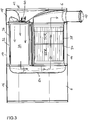
- an exhaust aftertreatment device 1 comprises a housing 2 with, for example, a cylindrical first housing shell 4 which houses or receives, for example, a particulate filter DPF and with a second housing shell 6, in which an exhaust gas inlet opening 8 for introducing uncleaned exhaust gases originating from a diesel internal combustion engine of a motor vehicle
- Exhaust outlet 10 has for discharging the pollutants at least partially purified exhaust gases from the exhaust aftertreatment device 1 in the atmosphere.
- the second housing shell 6 houses, for example, an oxidation catalytic converter (DOC) in the flow direction of the exhaust gas flow, a mixing device 12 for introducing a reducing agent into the exhaust gas flow and at least one reduction catalytic converter (SCR).
- DOC oxidation catalytic converter
- SCR reduction catalytic converter
- the second housing shell 6 has a cross-sectionally U-shaped cross-section with two transverse webs 14 connecting legs, a first leg 16 and a second leg 18, wherein the two Legs 16, 18 protrude, for example, perpendicularly from the ends of the crosspiece.
- the first housing shell 4 is releasably held between the first leg 16 and the second leg 18 of the second housing shell 2 by two releasable connections, a first releasable connection 20 and a second releasable connection 22. Especially by means of Figure 4 the U-shaped cross section of the second housing shell 6 is clearly visible.
- the oxidation catalyst (DOC) in the first leg 16 the mixing device 12 may be partially housed in the second leg 18 and partially in the transverse web 14 and the reduction catalyst (SCR) in the transverse web 14.
- the housing shells 4, 6 are preferably made of sheet steel, wherein in the second housing shell 6 of the transverse web 14 with the two legs 16, 18 is preferably welded.
- another cohesive or non-detachable connection or a detachable connection between the transverse web 14 and the two legs 16, 18 may be provided, for example a screw connection.
- a first fastening means 24, for example in the form of a mounting bracket is on a side facing away from the first housing shell 4 side surface 26 of the first leg 16 of the second housing shell 6 and a second fastening means 28, for example, also in the form of a mounting bracket on one of the first housing shell 4 away facing side surface 30 of the second leg 18 of the second housing shell 6 attached, for example by welding.
- the transverse web 14 may have two mutually separate transverse web floods, wherein in a first transverse web flow 32 a part of the
- transverse web flow 34 of the reduction catalyst SCR is arranged.
- the two transverse web floods 32, 34 each have, for example, in each case an inner housing shell 36, 38, which are then arranged and held within the transverse web 14.
- the mixing device 12 has an injection device 40 for injecting urea solution into the exhaust gas flow, which is here introduced, for example, from the outside into an opening 42 provided for this purpose in the second leg 18 and coaxial with the first transverse web flow 32 ( Fig.2 ) to inject the urea solution in a formed in the first cross-flow flood 32 mixing section 44 along which takes place a mixing of the injected urea solution with the exhaust gas stream.
- an injection device 40 for injecting urea solution into the exhaust gas flow which is here introduced, for example, from the outside into an opening 42 provided for this purpose in the second leg 18 and coaxial with the first transverse web flow 32 ( Fig.2 ) to inject the urea solution in a formed in the first cross-flow flood 32 mixing section 44 along which takes place a mixing of the injected urea solution with the exhaust gas stream.
- the second leg 18 may preferably be arranged swirl-forming agent, for example in the form of flow-conducting blades, which put the exhaust gas flow before entering the mixing section 44 in
- the exhaust gas flow introduced into the housing 2 through the exhaust gas inlet opening 8 in the first leg 16 is first guided through the oxidation catalyst DOC, which is arranged, for example, in the first leg 16 of the second housing shell 6. Subsequently, the partially purified exhaust gas flow passes via a flow connection from a free end 46 of the first leg 16 into a first end 48 of the first housing shell 4, in which, for example, the particle filter DPF is accommodated. This ensures filtering of particles flowing in the exhaust gas flow.
- the further purified exhaust gas flow passes through a further flow connection between a second end 50 of the first housing shell 4 and a free end of the second leg 18 of the second housing shell 6 in the second leg 18 and is deflected within the second leg 18 by approximately 90 degrees,
- swirl generating device to be added to spin before the swirled exhaust gas stream enters an inlet end of the first transverse flute 32 of the transverse web 14, in which the mixing section 44 is arranged.
- the urea solution which is preferably injected centrally and axially via the injection device 40 into the mixing section 44, then mixes with the exhaust gas stream which is offset in a twist.
- FIG. 3 shows the mixed with the urea solution exhaust gas flow then via an outlet end of the first cross-flow flood 32 in a deflecting shell 54 within the first leg 16, where the exhaust gas flow is deflected twice by about 90 degrees and introduced into an inlet end of the second cross-flow flood 34, in which the reduction catalyst SCR is housed. After at least partial removal of nitrogen oxides from the exhaust gas flow through the reduction catalyst SCR by means of selective catalytic reduction, this is introduced into an inlet end of the second leg 18 of the second housing shell 6 and from there into the exhaust gas outlet opening 10.
- the abutting surfaces and flow connections between the transverse web 14 and the two transverse web floods 32, 34 and the first leg 16 and between the transverse web 14 and the two transverse web floods 32, 34 and the second leg 18 are each preferably in a plane which is perpendicular to a Center axis 56 of the first housing shell 4 is.
- Figure 4 shows the situation in which the first housing shell 4 is pulled out of the second housing shell 6 after a release of the two detachable connections 20, 22. It can also be seen that the first leg 16 of the second housing shell 6 a first arranged perpendicular to its leg center plane and provided with at least a first flow opening 58 and the second leg 18 of the second housing shell 6 a second perpendicular to its leg center plane arranged with a second port 62 have provided nozzle 64.
- the two sockets 60, 64 are each formed cylindrically with a circular cross section and are arranged coaxially with respect to the central axis 56 of the first housing shell, wherein the two flow openings 58, 62 face each other.
- the free, mutually facing ends 46, 52 of the two sockets 60, 64 have an identical diameter. Furthermore, the diameters are at least in the region of the free ends 46, 52 of the two sockets 60, 64, for example, identical to the diameter of the first end 48 of the first housing shell 4 and the second end 50 of the first housing shell 4.
- the diameter in the region of the free End 46 of the first nozzle 60 also be different, for example, with respect to the diameter in the region of the free end 52 of the second nozzle 64, in which case the diameter in the region of the first end 48 of the first housing shell 4 with respect to the diameter in the region of the second End 50 of the first housing shell 4 is different in size because the free end 46 of the first port 60 is connected to the first end 48 of the first housing shell 4 and the free end 52 of the second port 64 to the second end 50 of the first housing shell 4.
- the first housing shell 4 is preferably held coaxially in the second housing shell 6 at its two ends 48, 50 with respect to the two sockets 60, 64.
- the free end 46 of the first socket 60, the first end 48 of the first housing shell 4, the second end 50 of the first housing shell 4 and the free end 52 of the second port 64 of the second housing shell 6 each have at least one descriptive circle and after radially outwardly projecting curl 66 or curl on.
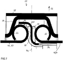
- Figure 7 shows a cross section of the first centering ring 68 in the region of the indirect impact of the free end 46 of the first nozzle 60 with the first end 48th the first housing shell 4 in an upper part in the drawing.
- the cross section of the first centering ring 68 in the region of the second end 50 of the first housing shell 4 and the free end 52 of the second nozzle 64 is then symmetrical with respect to a central plane perpendicular to the central axis 56 between the two sockets 60, 64th
- the two centering rings 68, 79 contact then the two housing shells 4, 6 in mounting planes 72, 74 indirectly.
- the two centering rings 68, 70 of the housing shells 4, 6 separate and separate component.
- FIG.10 is representative of the second centering ring 70 of the first centering ring 68 shown because the two centering rings 68, 70 are constructed identically.
- Each of the two centering rings 68, 70 has an inner centering collar 76, a middle section 78 and an outer centering collar 80.
- the inner Zentrierkragen 76 may extend over the entire circumference of the centering ring 68, 70 and be formed, for example, without circumferential gaps. Alternatively, circumferential gaps can also be present in the circumferential direction. Alternatively, the inner Zentrierkragen 80 seen in the circumferential direction may be formed only in sections and in particular also have circumferential gaps.
- the central portion 78 of the centering rings 68, 70 is preferably arranged in a plane perpendicular to the central axis 56 of the sockets 60, 64 and the first housing shell 4, while the inner Zentrierkragen 76 and the outer Zentrierkragen 80 each formed as a cylindrical collars and coaxial with respect to this center axis 56 are.
- the seals 82 are formed, for example, as flat gaskets, so that they are arranged tangentially to the circular peripheral surfaces of the flanges or curls 66 and therefore contact them on both sides linear.
- releasable connections 20, 22 are also conceivable without intermediate seals 82, in which the middle sections 78 of the centering rings 68, 70 respectively contact the curls or curls 66 directly.
- the two detachable connections 20, 22 therefore each contain one in 8 to Fig.10
- the outer centering collar 80 has such a circumferential recess 84 that for assembly and disassembly purposes, the first housing shell 4 and the second housing shell 6 relative to each other along the mounting planes 72, 74 are movable and detachable from each other and can be joined again.
- the outer centering collar 80 extends with respect to the entire circumference of a centering ring 68, 70 to at most over half the circumference of the respective centering ring 68, 70.
- the outer centering collar 80 extends over an angle of 180 degrees, as shown Figure 8 evident. Alternatively, it could also extend over a smaller angle than 180 degrees, for example over 160 degrees.
- the circumferential recess 84 or peripheral boundary of the outer centering collar 80 allows the two housing shells 4, 6 for mounting and dismounting the housing or for replacing the first housing shell 4 against a new first housing shell 4 along the mounting planes 72, 74 and in particular without displacement perpendicular to the mounting planes 72, 74 or without displacement along the central axis 56 can be moved relative to each other by, for example, the first housing shell 4 together with the first centering ring 68 and the second centering ring 70, the inner Zentrierkrägen 76 yes circumferentially on the radially inner peripheral surface of the first housing shell rest in the in Figure 4 and in Figure 7 pulled out by the arrow 86 direction out of the second housing shell 6 along the Montagebenen72, 74.
- the mounting planes 72, 74 are therefore defined as planes along which or parallel to which the first housing shell 4 and the second housing shell 6 are movable relative to each other, even if the two centering rings 68, 70 are already mounted.
- an outer centering collar 80 for mounting and for releasing the associated releasable connection 20, 22 has a circumferential recess 84 of such a size that a contacted by him housing shell 4 and 6 in the respective mounting plane 72, 74 can be moved freely in the direction ofmonsaus principleung 84, without the housing shell 4 and 6 for this purpose in the axial direction, ie perpendicular to the mounting plane 72nd , 74 would have to be moved.
- the two centering rings 68, 70 must be installed in a rotational position in which their circumferential recesses 84 are substantially aligned in the axial direction and have a desired assembly or disassembly direction.
- the two releasable connection 20, 22 additionally each comprise a clamping means 88 with a frusto-conical cross-section, which the crimps or curls 66 on the one hand at the free end 46 of the first nozzle and at the first end 48 of the first housing shell 4 and on the other hand at the free end 52nd of the second sleeve 64 and at the second end 50 of the first housing shell 4 by overlapping against each other.
- a clamping band 88 is used with frusto-conical cross-section.
- the first detachable connection 20 therefore ensures a tight flow connection between the first leg 16 of the second housing shell 6 and the first housing shell 4 and the second releasable connection 22 a tight flow connection between the first housing shell 4 and the second leg 18 of the second housing shell 6, wherein only by a release of the two clamping bands 88, a withdrawal of the first housing shell 4 from the second housing shell is made possible, as in Figure 4 is shown.
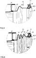
- Fig.5 and Fig.6 As can be seen, in the jacket walls in the region of the ends 46, 52, for example, the neck 60, 64 at least one fold or bead 90 may be formed such that these ends 46, 52 are elastically deformable. This allows a tolerance compensation, if, for example, angle or axis error between the first housing shell 4 and the nozzle 60, 64 are present.
- first housing shell 4 and the second housing shell 6 house, include or can accommodate any assemblies and elements of an exhaust aftertreatment device 1 and that the above-described assignment or placement of components and elements of the exhaust aftertreatment device 1 to or in the respective housing shells 4, 6 is purely exemplary.
Landscapes
- Engineering & Computer Science (AREA)
- General Engineering & Computer Science (AREA)
- Mechanical Engineering (AREA)
- Chemical & Material Sciences (AREA)
- Combustion & Propulsion (AREA)
- Exhaust Gas After Treatment (AREA)
Applications Claiming Priority (1)
| Application Number | Priority Date | Filing Date | Title |
|---|---|---|---|
| DE102017005356.1A DE102017005356A1 (de) | 2017-06-07 | 2017-06-07 | Abgasnachbehandlungsvorrichtung einer Brennkraftmaschine eines Kraftfahrzeugs |
Publications (2)
| Publication Number | Publication Date |
|---|---|
| EP3412879A1 true EP3412879A1 (fr) | 2018-12-12 |
| EP3412879B1 EP3412879B1 (fr) | 2020-03-11 |
Family
ID=62104174
Family Applications (1)
| Application Number | Title | Priority Date | Filing Date |
|---|---|---|---|
| EP18170326.5A Active EP3412879B1 (fr) | 2017-06-07 | 2018-05-02 | Dispositif de post-traitement de gaz d'échappement d'un moteur à combustion interne d'un véhicule automobile |
Country Status (2)
| Country | Link |
|---|---|
| EP (1) | EP3412879B1 (fr) |
| DE (1) | DE102017005356A1 (fr) |
Cited By (4)
| Publication number | Priority date | Publication date | Assignee | Title |
|---|---|---|---|---|
| EP3792463A1 (fr) * | 2019-09-16 | 2021-03-17 | Roth Technik Austria Gesellschaft Mit Beschränkter Haftung | Dispositif de traitement des gaz d'échappement pourvu d'agencements de traitement des gaz d'échappement échangeables par libération d'un composé soluble non destructif |
| WO2022162212A1 (fr) * | 2021-02-01 | 2022-08-04 | Dinex A/S | Système de traitement de gaz d'échappement compact avec filtre en état de service |
| US20230193891A1 (en) * | 2021-12-16 | 2023-06-22 | Shigeru Murata | Flange connection structure and diaphragm pump |
| EP4372215A3 (fr) * | 2022-11-21 | 2024-07-10 | HD Hyundai Infracore Co., Ltd. | Appareil de purification de gaz d'échappement et engin de construction le comprenant |
Citations (3)
| Publication number | Priority date | Publication date | Assignee | Title |
|---|---|---|---|---|
| DE10243644A1 (de) | 2002-09-19 | 2004-04-08 | Roth-Technik Austria Ges.M.B.H. | Lösbare Verbindung von Profilbauteilen |
| DE202005001616U1 (de) * | 2005-02-01 | 2005-05-25 | Roth-Technik Austria Ges.M.B.H. | Lösbare Verbindung von Profilbauteilen mit Zentrierringen |
| WO2008030639A2 (fr) * | 2006-09-07 | 2008-03-13 | Cummins Filtration Ip, Inc. | Ensemble de post-traitement d'échappement accessible pour l'entretien |
-
2017
- 2017-06-07 DE DE102017005356.1A patent/DE102017005356A1/de not_active Withdrawn
-
2018
- 2018-05-02 EP EP18170326.5A patent/EP3412879B1/fr active Active
Patent Citations (4)
| Publication number | Priority date | Publication date | Assignee | Title |
|---|---|---|---|---|
| DE10243644A1 (de) | 2002-09-19 | 2004-04-08 | Roth-Technik Austria Ges.M.B.H. | Lösbare Verbindung von Profilbauteilen |
| DE202005001616U1 (de) * | 2005-02-01 | 2005-05-25 | Roth-Technik Austria Ges.M.B.H. | Lösbare Verbindung von Profilbauteilen mit Zentrierringen |
| EP1686303A1 (fr) | 2005-02-01 | 2006-08-02 | ROTH-TECHNIK AUSTRIA Gesellschaft m.b.H. | Raccord démontable pour éléments profilés avec anneau de centrage |
| WO2008030639A2 (fr) * | 2006-09-07 | 2008-03-13 | Cummins Filtration Ip, Inc. | Ensemble de post-traitement d'échappement accessible pour l'entretien |
Cited By (8)
| Publication number | Priority date | Publication date | Assignee | Title |
|---|---|---|---|---|
| EP3792463A1 (fr) * | 2019-09-16 | 2021-03-17 | Roth Technik Austria Gesellschaft Mit Beschränkter Haftung | Dispositif de traitement des gaz d'échappement pourvu d'agencements de traitement des gaz d'échappement échangeables par libération d'un composé soluble non destructif |
| WO2022162212A1 (fr) * | 2021-02-01 | 2022-08-04 | Dinex A/S | Système de traitement de gaz d'échappement compact avec filtre en état de service |
| CN116783373A (zh) * | 2021-02-01 | 2023-09-19 | 迪耐斯集团 | 具有可维修过滤器的紧凑型废气处理系统 |
| US12104513B2 (en) | 2021-02-01 | 2024-10-01 | Dinex A/S | Compact exhaust gas treatment system with serviceable filter |
| US20230193891A1 (en) * | 2021-12-16 | 2023-06-22 | Shigeru Murata | Flange connection structure and diaphragm pump |
| US12123408B2 (en) * | 2021-12-16 | 2024-10-22 | Shigeru Murata | Flange connection structure and diaphragm pump |
| EP4372215A3 (fr) * | 2022-11-21 | 2024-07-10 | HD Hyundai Infracore Co., Ltd. | Appareil de purification de gaz d'échappement et engin de construction le comprenant |
| US12410738B2 (en) | 2022-11-21 | 2025-09-09 | Hd Hyundai Infracore Co., Ltd. | Exhaust gas purification apparatus and construction machinery including the same |
Also Published As
| Publication number | Publication date |
|---|---|
| EP3412879B1 (fr) | 2020-03-11 |
| DE102017005356A1 (de) | 2018-12-13 |
Similar Documents
| Publication | Publication Date | Title |
|---|---|---|
| DE102011077156B4 (de) | Abgasanlage und Injektionsmodul | |
| EP2233709B1 (fr) | Dispositif de traitement de gaz d'échappement | |
| EP2535535B1 (fr) | Mélangeur statique | |
| EP3412879B1 (fr) | Dispositif de post-traitement de gaz d'échappement d'un moteur à combustion interne d'un véhicule automobile | |
| EP2161423A1 (fr) | Installation de gaz d'échappement pour véhicules diesel dotés d'un catalyseur SCR | |
| EP2420656B1 (fr) | Dispositif de nettoyage des gaz d'échappement, installation de gaz d'échappement, procédé de démontage | |
| EP2233708A1 (fr) | Dispositif de traitement des gaz d'échappement | |
| EP3443209B1 (fr) | Dispositif de post-traitement des gaz d'échappement doté d'un catalyseur et d'un dispositif de mélange | |
| EP2022956A2 (fr) | Dispositif de guidage de l'écoulement et système d'échappement ainsi équipé | |
| DE102016211703A1 (de) | Mischervorrichtung für ein Abgasnachbehandlungssystem eines Kraftfahrzeugs, Abgasnachbehandlungssystem und Kraftfahrzeug | |
| AT516102A1 (de) | Abgasreinigungsvorrichtung für ein Fahrzeug, insbesondere für ein Nutzfahrzeug | |
| EP2726718A1 (fr) | Dispositif et procédé d'introduction d'un réducteur dans une ligne d'échappement | |
| EP2461887B1 (fr) | Dispositif de filtration et utilisation d'un élément filtre enroulé | |
| DE102016120171A1 (de) | Mischerbaugruppe | |
| DE102018107766A1 (de) | Abgasanlage und Mischerbaugruppe für eine Abgasanlage | |
| EP2616649B1 (fr) | Unité de traitement de gaz d'échappement, en particulier pour une conduite de recyclage de gaz d'échappement | |
| DE10296178B4 (de) | Flexibles Leitungselement | |
| EP1437489B2 (fr) | Système pour gaz d'échappement | |
| EP3680463A1 (fr) | Mélangeur pour une installation de gaz d'échappement d'un moteur à combustion interne | |
| EP3549662B1 (fr) | Module mélangeur | |
| EP3792463B1 (fr) | Dispositif de traitement des gaz d'échappement pourvu d'agencements de traitement des gaz d'échappement échangeables par libération d'un composé soluble non destructif | |
| EP1686303B1 (fr) | Raccord démontable pour éléments profilés avec anneau de centrage | |
| EP3770396B1 (fr) | Dispositif de post-traitement des gaz d'échappement pour une installation de gaz d'échappement d'un véhicule automobile ainsi que véhicule automobile doté d'un tel dispositif de post-traitement des gaz d'échappement | |
| DE19959241C1 (de) | Abgasreinigungsvorrichtung | |
| DE102014003686A1 (de) | Abgasnachbehandlungseinrichtung, Abgasnachbehandlungssystem, Brennkraftmaschine und Kraftfahrzeug |
Legal Events
| Date | Code | Title | Description |
|---|---|---|---|
| PUAI | Public reference made under article 153(3) epc to a published international application that has entered the european phase |
Free format text: ORIGINAL CODE: 0009012 |
|
| STAA | Information on the status of an ep patent application or granted ep patent |
Free format text: STATUS: THE APPLICATION HAS BEEN PUBLISHED |
|
| AK | Designated contracting states |
Kind code of ref document: A1 Designated state(s): AL AT BE BG CH CY CZ DE DK EE ES FI FR GB GR HR HU IE IS IT LI LT LU LV MC MK MT NL NO PL PT RO RS SE SI SK SM TR |
|
| AX | Request for extension of the european patent |
Extension state: BA ME |
|
| STAA | Information on the status of an ep patent application or granted ep patent |
Free format text: STATUS: REQUEST FOR EXAMINATION WAS MADE |
|
| 17P | Request for examination filed |
Effective date: 20190612 |
|
| RBV | Designated contracting states (corrected) |
Designated state(s): AL AT BE BG CH CY CZ DE DK EE ES FI FR GB GR HR HU IE IS IT LI LT LU LV MC MK MT NL NO PL PT RO RS SE SI SK SM TR |
|
| RIC1 | Information provided on ipc code assigned before grant |
Ipc: F01N 13/00 20100101ALI20190826BHEP Ipc: F01N 13/18 20100101ALI20190826BHEP Ipc: F01N 3/02 20060101AFI20190826BHEP Ipc: F16L 23/04 20060101ALI20190826BHEP |
|
| GRAP | Despatch of communication of intention to grant a patent |
Free format text: ORIGINAL CODE: EPIDOSNIGR1 |
|
| STAA | Information on the status of an ep patent application or granted ep patent |
Free format text: STATUS: GRANT OF PATENT IS INTENDED |
|
| INTG | Intention to grant announced |
Effective date: 20191017 |
|
| GRAS | Grant fee paid |
Free format text: ORIGINAL CODE: EPIDOSNIGR3 |
|
| GRAA | (expected) grant |
Free format text: ORIGINAL CODE: 0009210 |
|
| STAA | Information on the status of an ep patent application or granted ep patent |
Free format text: STATUS: THE PATENT HAS BEEN GRANTED |
|
| AK | Designated contracting states |
Kind code of ref document: B1 Designated state(s): AL AT BE BG CH CY CZ DE DK EE ES FI FR GB GR HR HU IE IS IT LI LT LU LV MC MK MT NL NO PL PT RO RS SE SI SK SM TR |
|
| REG | Reference to a national code |
Ref country code: GB Ref legal event code: FG4D Free format text: NOT ENGLISH |
|
| REG | Reference to a national code |
Ref country code: CH Ref legal event code: EP |
|
| REG | Reference to a national code |
Ref country code: AT Ref legal event code: REF Ref document number: 1243397 Country of ref document: AT Kind code of ref document: T Effective date: 20200315 |
|
| REG | Reference to a national code |
Ref country code: IE Ref legal event code: FG4D Free format text: LANGUAGE OF EP DOCUMENT: GERMAN |
|
| REG | Reference to a national code |
Ref country code: DE Ref legal event code: R096 Ref document number: 502018000918 Country of ref document: DE |
|
| REG | Reference to a national code |
Ref country code: NL Ref legal event code: FP |
|
| REG | Reference to a national code |
Ref country code: CH Ref legal event code: NV Representative=s name: VALIPAT S.A. C/O BOVARD SA NEUCHATEL, CH |
|
| REG | Reference to a national code |
Ref country code: SE Ref legal event code: TRGR |
|
| PG25 | Lapsed in a contracting state [announced via postgrant information from national office to epo] |
Ref country code: NO Free format text: LAPSE BECAUSE OF FAILURE TO SUBMIT A TRANSLATION OF THE DESCRIPTION OR TO PAY THE FEE WITHIN THE PRESCRIBED TIME-LIMIT Effective date: 20200611 Ref country code: FI Free format text: LAPSE BECAUSE OF FAILURE TO SUBMIT A TRANSLATION OF THE DESCRIPTION OR TO PAY THE FEE WITHIN THE PRESCRIBED TIME-LIMIT Effective date: 20200311 Ref country code: RS Free format text: LAPSE BECAUSE OF FAILURE TO SUBMIT A TRANSLATION OF THE DESCRIPTION OR TO PAY THE FEE WITHIN THE PRESCRIBED TIME-LIMIT Effective date: 20200311 |
|
| PG25 | Lapsed in a contracting state [announced via postgrant information from national office to epo] |
Ref country code: GR Free format text: LAPSE BECAUSE OF FAILURE TO SUBMIT A TRANSLATION OF THE DESCRIPTION OR TO PAY THE FEE WITHIN THE PRESCRIBED TIME-LIMIT Effective date: 20200612 Ref country code: HR Free format text: LAPSE BECAUSE OF FAILURE TO SUBMIT A TRANSLATION OF THE DESCRIPTION OR TO PAY THE FEE WITHIN THE PRESCRIBED TIME-LIMIT Effective date: 20200311 Ref country code: LV Free format text: LAPSE BECAUSE OF FAILURE TO SUBMIT A TRANSLATION OF THE DESCRIPTION OR TO PAY THE FEE WITHIN THE PRESCRIBED TIME-LIMIT Effective date: 20200311 Ref country code: BG Free format text: LAPSE BECAUSE OF FAILURE TO SUBMIT A TRANSLATION OF THE DESCRIPTION OR TO PAY THE FEE WITHIN THE PRESCRIBED TIME-LIMIT Effective date: 20200611 |
|
| REG | Reference to a national code |
Ref country code: LT Ref legal event code: MG4D |
|
| PG25 | Lapsed in a contracting state [announced via postgrant information from national office to epo] |
Ref country code: EE Free format text: LAPSE BECAUSE OF FAILURE TO SUBMIT A TRANSLATION OF THE DESCRIPTION OR TO PAY THE FEE WITHIN THE PRESCRIBED TIME-LIMIT Effective date: 20200311 Ref country code: SM Free format text: LAPSE BECAUSE OF FAILURE TO SUBMIT A TRANSLATION OF THE DESCRIPTION OR TO PAY THE FEE WITHIN THE PRESCRIBED TIME-LIMIT Effective date: 20200311 Ref country code: LT Free format text: LAPSE BECAUSE OF FAILURE TO SUBMIT A TRANSLATION OF THE DESCRIPTION OR TO PAY THE FEE WITHIN THE PRESCRIBED TIME-LIMIT Effective date: 20200311 Ref country code: CZ Free format text: LAPSE BECAUSE OF FAILURE TO SUBMIT A TRANSLATION OF THE DESCRIPTION OR TO PAY THE FEE WITHIN THE PRESCRIBED TIME-LIMIT Effective date: 20200311 Ref country code: RO Free format text: LAPSE BECAUSE OF FAILURE TO SUBMIT A TRANSLATION OF THE DESCRIPTION OR TO PAY THE FEE WITHIN THE PRESCRIBED TIME-LIMIT Effective date: 20200311 Ref country code: IS Free format text: LAPSE BECAUSE OF FAILURE TO SUBMIT A TRANSLATION OF THE DESCRIPTION OR TO PAY THE FEE WITHIN THE PRESCRIBED TIME-LIMIT Effective date: 20200711 Ref country code: SK Free format text: LAPSE BECAUSE OF FAILURE TO SUBMIT A TRANSLATION OF THE DESCRIPTION OR TO PAY THE FEE WITHIN THE PRESCRIBED TIME-LIMIT Effective date: 20200311 Ref country code: PT Free format text: LAPSE BECAUSE OF FAILURE TO SUBMIT A TRANSLATION OF THE DESCRIPTION OR TO PAY THE FEE WITHIN THE PRESCRIBED TIME-LIMIT Effective date: 20200805 |
|
| REG | Reference to a national code |
Ref country code: DE Ref legal event code: R097 Ref document number: 502018000918 Country of ref document: DE |
|
| PLBE | No opposition filed within time limit |
Free format text: ORIGINAL CODE: 0009261 |
|
| STAA | Information on the status of an ep patent application or granted ep patent |
Free format text: STATUS: NO OPPOSITION FILED WITHIN TIME LIMIT |
|
| PG25 | Lapsed in a contracting state [announced via postgrant information from national office to epo] |
Ref country code: ES Free format text: LAPSE BECAUSE OF FAILURE TO SUBMIT A TRANSLATION OF THE DESCRIPTION OR TO PAY THE FEE WITHIN THE PRESCRIBED TIME-LIMIT Effective date: 20200311 Ref country code: DK Free format text: LAPSE BECAUSE OF FAILURE TO SUBMIT A TRANSLATION OF THE DESCRIPTION OR TO PAY THE FEE WITHIN THE PRESCRIBED TIME-LIMIT Effective date: 20200311 Ref country code: MC Free format text: LAPSE BECAUSE OF FAILURE TO SUBMIT A TRANSLATION OF THE DESCRIPTION OR TO PAY THE FEE WITHIN THE PRESCRIBED TIME-LIMIT Effective date: 20200311 |
|
| 26N | No opposition filed |
Effective date: 20201214 |
|
| PG25 | Lapsed in a contracting state [announced via postgrant information from national office to epo] |
Ref country code: PL Free format text: LAPSE BECAUSE OF FAILURE TO SUBMIT A TRANSLATION OF THE DESCRIPTION OR TO PAY THE FEE WITHIN THE PRESCRIBED TIME-LIMIT Effective date: 20200311 Ref country code: SI Free format text: LAPSE BECAUSE OF FAILURE TO SUBMIT A TRANSLATION OF THE DESCRIPTION OR TO PAY THE FEE WITHIN THE PRESCRIBED TIME-LIMIT Effective date: 20200311 |
|
| PG25 | Lapsed in a contracting state [announced via postgrant information from national office to epo] |
Ref country code: LU Free format text: LAPSE BECAUSE OF NON-PAYMENT OF DUE FEES Effective date: 20200502 |
|
| PG25 | Lapsed in a contracting state [announced via postgrant information from national office to epo] |
Ref country code: IE Free format text: LAPSE BECAUSE OF NON-PAYMENT OF DUE FEES Effective date: 20200502 |
|
| PG25 | Lapsed in a contracting state [announced via postgrant information from national office to epo] |
Ref country code: TR Free format text: LAPSE BECAUSE OF FAILURE TO SUBMIT A TRANSLATION OF THE DESCRIPTION OR TO PAY THE FEE WITHIN THE PRESCRIBED TIME-LIMIT Effective date: 20200311 Ref country code: MT Free format text: LAPSE BECAUSE OF FAILURE TO SUBMIT A TRANSLATION OF THE DESCRIPTION OR TO PAY THE FEE WITHIN THE PRESCRIBED TIME-LIMIT Effective date: 20200311 Ref country code: CY Free format text: LAPSE BECAUSE OF FAILURE TO SUBMIT A TRANSLATION OF THE DESCRIPTION OR TO PAY THE FEE WITHIN THE PRESCRIBED TIME-LIMIT Effective date: 20200311 |
|
| PG25 | Lapsed in a contracting state [announced via postgrant information from national office to epo] |
Ref country code: MK Free format text: LAPSE BECAUSE OF FAILURE TO SUBMIT A TRANSLATION OF THE DESCRIPTION OR TO PAY THE FEE WITHIN THE PRESCRIBED TIME-LIMIT Effective date: 20200311 Ref country code: AL Free format text: LAPSE BECAUSE OF FAILURE TO SUBMIT A TRANSLATION OF THE DESCRIPTION OR TO PAY THE FEE WITHIN THE PRESCRIBED TIME-LIMIT Effective date: 20200311 |
|
| PGFP | Annual fee paid to national office [announced via postgrant information from national office to epo] |
Ref country code: NL Payment date: 20250522 Year of fee payment: 8 |
|
| PGFP | Annual fee paid to national office [announced via postgrant information from national office to epo] |
Ref country code: DE Payment date: 20250430 Year of fee payment: 8 |
|
| PGFP | Annual fee paid to national office [announced via postgrant information from national office to epo] |
Ref country code: GB Payment date: 20250522 Year of fee payment: 8 |
|
| PGFP | Annual fee paid to national office [announced via postgrant information from national office to epo] |
Ref country code: BE Payment date: 20250520 Year of fee payment: 8 Ref country code: IT Payment date: 20250530 Year of fee payment: 8 |
|
| PGFP | Annual fee paid to national office [announced via postgrant information from national office to epo] |
Ref country code: FR Payment date: 20250521 Year of fee payment: 8 |
|
| PGFP | Annual fee paid to national office [announced via postgrant information from national office to epo] |
Ref country code: CH Payment date: 20250601 Year of fee payment: 8 |
|
| PGFP | Annual fee paid to national office [announced via postgrant information from national office to epo] |
Ref country code: AT Payment date: 20250519 Year of fee payment: 8 |
|
| PGFP | Annual fee paid to national office [announced via postgrant information from national office to epo] |
Ref country code: SE Payment date: 20250522 Year of fee payment: 8 |