EP3413029B1 - Procédé de vérification d'anomalie d'unité d'inspection, appareil d'inspection, et système d'inspection - Google Patents
Procédé de vérification d'anomalie d'unité d'inspection, appareil d'inspection, et système d'inspection Download PDFInfo
- Publication number
- EP3413029B1 EP3413029B1 EP17747815.3A EP17747815A EP3413029B1 EP 3413029 B1 EP3413029 B1 EP 3413029B1 EP 17747815 A EP17747815 A EP 17747815A EP 3413029 B1 EP3413029 B1 EP 3413029B1
- Authority
- EP
- European Patent Office
- Prior art keywords
- inspection unit
- verification
- inspection
- image data
- fault
- Prior art date
- Legal status (The legal status is an assumption and is not a legal conclusion. Google has not performed a legal analysis and makes no representation as to the accuracy of the status listed.)
- Active
Links
Images






Classifications
-
- G—PHYSICS
- G06—COMPUTING OR CALCULATING; COUNTING
- G06T—IMAGE DATA PROCESSING OR GENERATION, IN GENERAL
- G06T7/00—Image analysis
- G06T7/0002—Inspection of images, e.g. flaw detection
- G06T7/0004—Industrial image inspection
- G06T7/001—Industrial image inspection using an image reference approach
-
- G—PHYSICS
- G01—MEASURING; TESTING
- G01N—INVESTIGATING OR ANALYSING MATERIALS BY DETERMINING THEIR CHEMICAL OR PHYSICAL PROPERTIES
- G01N21/00—Investigating or analysing materials by the use of optical means, i.e. using sub-millimetre waves, infrared, visible or ultraviolet light
- G01N21/84—Systems specially adapted for particular applications
- G01N21/88—Investigating the presence of flaws or contamination
- G01N21/95—Investigating the presence of flaws or contamination characterised by the material or shape of the object to be examined
-
- G—PHYSICS
- G01—MEASURING; TESTING
- G01B—MEASURING LENGTH, THICKNESS OR SIMILAR LINEAR DIMENSIONS; MEASURING ANGLES; MEASURING AREAS; MEASURING IRREGULARITIES OF SURFACES OR CONTOURS
- G01B11/00—Measuring arrangements characterised by the use of optical techniques
- G01B11/02—Measuring arrangements characterised by the use of optical techniques for measuring length, width or thickness
- G01B11/06—Measuring arrangements characterised by the use of optical techniques for measuring length, width or thickness for measuring thickness ; e.g. of sheet material
- G01B11/0608—Height gauges
-
- G—PHYSICS
- G01—MEASURING; TESTING
- G01M—TESTING STATIC OR DYNAMIC BALANCE OF MACHINES OR STRUCTURES; TESTING OF STRUCTURES OR APPARATUS, NOT OTHERWISE PROVIDED FOR
- G01M11/00—Testing of optical apparatus; Testing structures by optical methods not otherwise provided for
- G01M11/02—Testing optical properties
-
- G—PHYSICS
- G01—MEASURING; TESTING
- G01M—TESTING STATIC OR DYNAMIC BALANCE OF MACHINES OR STRUCTURES; TESTING OF STRUCTURES OR APPARATUS, NOT OTHERWISE PROVIDED FOR
- G01M11/00—Testing of optical apparatus; Testing structures by optical methods not otherwise provided for
- G01M11/02—Testing optical properties
- G01M11/06—Testing the alignment of vehicle headlight devices
-
- G—PHYSICS
- G01—MEASURING; TESTING
- G01N—INVESTIGATING OR ANALYSING MATERIALS BY DETERMINING THEIR CHEMICAL OR PHYSICAL PROPERTIES
- G01N21/00—Investigating or analysing materials by the use of optical means, i.e. using sub-millimetre waves, infrared, visible or ultraviolet light
- G01N21/01—Arrangements or apparatus for facilitating the optical investigation
-
- G—PHYSICS
- G01—MEASURING; TESTING
- G01N—INVESTIGATING OR ANALYSING MATERIALS BY DETERMINING THEIR CHEMICAL OR PHYSICAL PROPERTIES
- G01N21/00—Investigating or analysing materials by the use of optical means, i.e. using sub-millimetre waves, infrared, visible or ultraviolet light
- G01N21/01—Arrangements or apparatus for facilitating the optical investigation
- G01N21/13—Moving of cuvettes or solid samples to or from the investigating station
-
- G—PHYSICS
- G01—MEASURING; TESTING
- G01N—INVESTIGATING OR ANALYSING MATERIALS BY DETERMINING THEIR CHEMICAL OR PHYSICAL PROPERTIES
- G01N21/00—Investigating or analysing materials by the use of optical means, i.e. using sub-millimetre waves, infrared, visible or ultraviolet light
- G01N21/84—Systems specially adapted for particular applications
- G01N21/88—Investigating the presence of flaws or contamination
-
- G—PHYSICS
- G01—MEASURING; TESTING
- G01N—INVESTIGATING OR ANALYSING MATERIALS BY DETERMINING THEIR CHEMICAL OR PHYSICAL PROPERTIES
- G01N21/00—Investigating or analysing materials by the use of optical means, i.e. using sub-millimetre waves, infrared, visible or ultraviolet light
- G01N21/84—Systems specially adapted for particular applications
- G01N21/88—Investigating the presence of flaws or contamination
- G01N21/95—Investigating the presence of flaws or contamination characterised by the material or shape of the object to be examined
- G01N21/956—Inspecting patterns on the surface of objects
-
- G—PHYSICS
- G06—COMPUTING OR CALCULATING; COUNTING
- G06T—IMAGE DATA PROCESSING OR GENERATION, IN GENERAL
- G06T7/00—Image analysis
- G06T7/70—Determining position or orientation of objects or cameras
- G06T7/73—Determining position or orientation of objects or cameras using feature-based methods
-
- G—PHYSICS
- G06—COMPUTING OR CALCULATING; COUNTING
- G06T—IMAGE DATA PROCESSING OR GENERATION, IN GENERAL
- G06T7/00—Image analysis
- G06T7/80—Analysis of captured images to determine intrinsic or extrinsic camera parameters, i.e. camera calibration
-
- H—ELECTRICITY
- H05—ELECTRIC TECHNIQUES NOT OTHERWISE PROVIDED FOR
- H05K—PRINTED CIRCUITS; CASINGS OR CONSTRUCTIONAL DETAILS OF ELECTRIC APPARATUS; MANUFACTURE OF ASSEMBLAGES OF ELECTRICAL COMPONENTS
- H05K13/00—Apparatus or processes specially adapted for manufacturing or adjusting assemblages of electric components
- H05K13/08—Monitoring manufacture of assemblages
- H05K13/081—Integration of optical monitoring devices in assembly lines; Processes using optical monitoring devices specially adapted for controlling devices or machines in assembly lines
- H05K13/0815—Controlling of component placement on the substrate during or after manufacturing
-
- H—ELECTRICITY
- H05—ELECTRIC TECHNIQUES NOT OTHERWISE PROVIDED FOR
- H05K—PRINTED CIRCUITS; CASINGS OR CONSTRUCTIONAL DETAILS OF ELECTRIC APPARATUS; MANUFACTURE OF ASSEMBLAGES OF ELECTRICAL COMPONENTS
- H05K13/00—Apparatus or processes specially adapted for manufacturing or adjusting assemblages of electric components
- H05K13/08—Monitoring manufacture of assemblages
- H05K13/089—Calibration, teaching or correction of mechanical systems, e.g. of the mounting head
-
- G—PHYSICS
- G01—MEASURING; TESTING
- G01N—INVESTIGATING OR ANALYSING MATERIALS BY DETERMINING THEIR CHEMICAL OR PHYSICAL PROPERTIES
- G01N21/00—Investigating or analysing materials by the use of optical means, i.e. using sub-millimetre waves, infrared, visible or ultraviolet light
- G01N21/84—Systems specially adapted for particular applications
- G01N21/88—Investigating the presence of flaws or contamination
- G01N21/95—Investigating the presence of flaws or contamination characterised by the material or shape of the object to be examined
- G01N21/956—Inspecting patterns on the surface of objects
- G01N2021/95638—Inspecting patterns on the surface of objects for PCB's
-
- G—PHYSICS
- G01—MEASURING; TESTING
- G01N—INVESTIGATING OR ANALYSING MATERIALS BY DETERMINING THEIR CHEMICAL OR PHYSICAL PROPERTIES
- G01N21/00—Investigating or analysing materials by the use of optical means, i.e. using sub-millimetre waves, infrared, visible or ultraviolet light
- G01N21/84—Systems specially adapted for particular applications
- G01N21/88—Investigating the presence of flaws or contamination
- G01N21/95—Investigating the presence of flaws or contamination characterised by the material or shape of the object to be examined
- G01N21/956—Inspecting patterns on the surface of objects
- G01N2021/95638—Inspecting patterns on the surface of objects for PCB's
- G01N2021/95646—Soldering
-
- G—PHYSICS
- G06—COMPUTING OR CALCULATING; COUNTING
- G06T—IMAGE DATA PROCESSING OR GENERATION, IN GENERAL
- G06T2207/00—Indexing scheme for image analysis or image enhancement
- G06T2207/30—Subject of image; Context of image processing
- G06T2207/30108—Industrial image inspection
- G06T2207/30141—Printed circuit board [PCB]
Definitions
- the driving unit includes a rotating unit configured to rotate the cover to open and close the verification reference body.
- the inspection apparatus further includes a reflector disposed on the frame to verify whether a light source, configured to generate light, in the inspection unit has a fault.
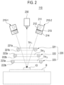
- the first lighting portions 210-1 and 210-2 include a light source 211 configured to generate light, a grating element 212 configured to convert the light from the light source 211 into pattern light, a grating-moving apparatus 213 configured to pitch-move the grating element 212, and a projection lens 214 configured to project the pattern light, which is converted by the grating element 212, onto the inspection object IO.
- the grating element 212 may be moved by a predetermined distance (e.g., 2 ⁇ /N (where N is a natural number of 2 or more) through the grating-moving apparatus 213, such as a PZT (piezo) actuator, for phase transition of the pattern light.
- the present disclosure is not limited thereto and any other means may be used as long as it can radiate pattern light.
- the first lamp 221 may generate at least one color light.
- the first lamp 221 may generate color light having a first color (e.g., red).
- the first lamp 221 may generate color lights of red, green, and blue.
- the second lamp 222 is installed under the first lamp 221.
- the second lamp 222 generates color light and radiates the color light towards the inspected body B.
- the second lamp 222 may have a shape of a circle or a virtual polygon, however the second lamp 222 is not limited thereto.
- the second lamp 222 may generate at least one color light.
- the second lamp 222 may generate a color light having a color (e.g., green) that is different from that of the color light generated by the first lamp 221.
- the second lamp 222 may generate color lights of red, green, and blue.
- the third lamp 223 is installed under the second lamp 222.
- the third lamp 223 generates color light, and radiates the color light towards the inspected body B.
- the third lamp 223 may have a shape of a circle or a virtual polygon, however the third lamp 223 is not limited thereto.
- the third lamp 223 includes a third ring member 223a having an opening TH 3 for passing light (e.g., pattern light or color light) and at least one third light emitting element 223b, which is installed under the third ring member 223a, as a light source for generating the color light.
- the opening TH 3 of the third lamp 223 may be larger in diameter than the opening TH 2 of the second lamp 222 so that the pattern light from the first lighting portions 210-1 and 210-2 or the color light from the first lamp 221 or second lamp 222 can be radiated towards the inspected body B or the light (e.g., pattern light or color light) reflected from the inspected body B can be radiated.
- the third lamp 223 may generate at least one color light.
- the third lamp 223 may generate a color light having a color (e.g., green) that is different from that of the color light generated by the first lamp 221 and the second lamp 222.
- the third lamp 223 may generate color lights of red, green, and blue.
- the second lighting portion 220 includes the first lamp 221, the second lamp 222, and the third lamp 223 in the embodiment described above, however the second lighting portion 220 is not limited thereto.
- the second lighting portion 220 may include at least one lamp.
- the inspection unit 110 further includes an imaging portion 230.
- the imaging portion 230 obtains image data of the inspected body B by receiving light reflected by the inspected body B. That is, the imaging portion 230 obtains the image data of the inspected body B by photographing the inspected body B through the radiation of the pattern light from the first lighting portions 210-1 and 210-2. Further, the imaging portion 230 obtains the image data of the inspected body B by photographing the inspected body B through the radiation of the color light from the second lighting portion 220. As one example, the imaging portion 230 may be installed at an upper position perpendicular to the inspected body B.
- a plurality of imaging portions 230 may be installed at an upper position perpendicular to the inspected body B and may be installed along a circumferential direction to be spaced apart by a predetermined angle.
- the imaging portion 230 may be a charge coupled device (CCD) camera or a complementary metal oxide semiconductor (CMOS) camera, however the imaging portion 230 is not limited thereto.
- the inspection unit 110 shown in FIG. 2 is an example of an inspection device that can obtain image data of the inspected body B, so it should be noted that the inspection unit 110 is not limited to the configuration shown in FIG. 2 .
- the inspection system 100 further includes a moving unit 120.
- the moving unit 120 moves the inspected body B to the inspection unit 110.
- the moving unit 120 may include a conveyer (not shown) or the like, but the moving unit 120 is not limited thereto.
- the inspection system 100 further includes an inspection apparatus 130 for verifying whether the inspection unit 110 has a fault.
- the inspection apparatus 130 may be attached to a side of the inspection system 100.
- the inspection apparatus 130 is attached to a side of the moving unit 120, however the inspection apparatus 130 is not limited thereto.
- FIG. 3 is a perspective view schematically showing a configuration of the inspection apparatus 130 according to an embodiment of the present disclosure.
- the inspecting apparatus 130 includes a frame 310 that can be attached to the inspection system 100, and a verification reference body 320 formed on the frame 310.
- the verification reference body 320 may be disposed in a concave portion of the frame 310 as shown in FIG. 3 , however the verification reference body 320 is not limited thereto.
- the verification reference body 320 may be disposed on the frame 310.
- the verification reference body 320 includes a first verification target 321, a second verification target 322, and a third verification target 323.
- the first verification target 321 is a verification target that indicates a height reference for verifying light radiated from the inspection unit 110 and a reference plane for measuring height of the inspection unit 110.
- the first verification target 321 includes a flat plate 321b having a flat area 321a that indicates the height reference. Also, the flat area 321a can indicate one or more gray level (e.g., gray) or a color including one or more gray level.
- the second verification target 322 is a verification target for verifying the accuracy of movement of the inspection unit 110. That is, the second verification target 322 is a verification target for verifying whether the inspection unit 110 moves accurately to a predetermined position.
- the second verification target 322 includes at least two fiducial markers representing at least two positions for verifying the accuracy of movement of the inspection unit 110.
- the second verification target 322 includes a first fiducial marker 322a, a second fiducial marker 322b, and a third fiducial marker 322c, as shown in FIG. 3 .
- the first to third fiducial markers 322a to 322c are markers for verifying the movement of the inspection unit 110, and in detail, the first to third fiducial markers 322a to 322c are markers for verifying X and Y offset or X, Y, and Z skew.
- the second verification target 322 may include two fiducial markers and the two fiducial markers may be disposed in parallel with the longitudinal direction of the frame 310 or may be disposed at different positions.
- the third verification target 323 is a verification target for verifying the accuracy of height measurement of the inspection unit 110.
- the third verification target 323 includes at least one height target having a predetermined height for verifying the accuracy of height measurement of the inspection unit 110.
- the third verification target 323 includes a first height target 323a having a first height and a second height target 323b having a second height, as shown in FIG. 3 .
- the second verification target 322, that is, the at least two fiducial markers may be disposed around the flat area 321a.
- the third verification target 323, that is, the at least one height marker may be disposed around the flat area 321a.
- the flat area 321a may be defined by the second verification target 322, that is, the at least two fiducial markers. Further, the third verification target 323, that is, the height marker may be disposed around the flat area 321a.
- the inspection apparatus 130 further includes a cover 330.
- the cover 330 opens the verification reference body 320 while a fault of the inspection unit 110 is verified, and covers the verification reference body 320 to prevent dirt, dust or the like from entering the verification reference body 320 while a defect of the inspection unit 110 is not verified.
- the inspection apparatus 130 further includes a stopper 350.
- the stopper 350 supports the cover 330 to maintain the cover 330, which is moved by the driving unit 340, over the verification reference body 320.
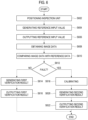
- the controller 140 performs the calibration of the inspection unit 110 based on the image data of the second verification target 322 and the predetermined reference data (S618). For example, the controller 140 performs the calibration of the inspection unit 110 to correct the error between the positions of the first to third fiducial markers 322a to 322c in the image data of the second verification target 322 and the positions of the first to third fiducial markers 322a to 322c in the predetermined reference data.
- the controller 140 may generate second verification result information indicating that the inspection unit 110 has a fault (S620), and may output the second verification result information through the output unit (S622).
- the second verification result information may include a verification result value of the inspection unit 110.
- the second verification result information may be output in various forms (e.g., text, sound or the like).
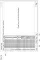
- the controller 140 may generate a chart 1110 of the verification result information based on the verification result information corresponding to the chart display request information, as shown in FIG. 11 .
- reference numeral 1120 indicates a fault limit, that is, an error limit
- reference numeral 1130 indicates a warning limit
- reference numeral 1140 indicates a reference value
- reference numeral 1150 indicates the verification result information.
- the horizontal axis of the chart 1110 is an index of the list of the verification result information and the vertical axis is a verification result value of the verification result information.
Landscapes
- Engineering & Computer Science (AREA)
- Physics & Mathematics (AREA)
- General Physics & Mathematics (AREA)
- Analytical Chemistry (AREA)
- Chemical & Material Sciences (AREA)
- Biochemistry (AREA)
- Life Sciences & Earth Sciences (AREA)
- Pathology (AREA)
- Immunology (AREA)
- General Health & Medical Sciences (AREA)
- Health & Medical Sciences (AREA)
- Manufacturing & Machinery (AREA)
- Operations Research (AREA)
- Microelectronics & Electronic Packaging (AREA)
- Computer Vision & Pattern Recognition (AREA)
- Theoretical Computer Science (AREA)
- Quality & Reliability (AREA)
- Investigating Materials By The Use Of Optical Means Adapted For Particular Applications (AREA)
- Geometry (AREA)
Claims (12)
- Procédé permettant de vérifier si une unité d'inspection (110), capable d'inspecter un défaut d'un corps inspecté dans un système d'inspection (100), présente ou non un défaut, le procédé comprenant :
la fourniture d'un corps de référence de vérification (320) formé sur un châssis (310) attaché au système d'inspection (100), le corps de référence de vérification (320) comprenant :une première cible de vérification (321) incluant une plaque plane (321b) ayant une zone plane (321a) capable d'indiquer une référence de hauteur pour vérifier la lumière irradiée par l'unité d'inspection (110), un plan de référence pour mesurer la hauteur de l'unité d'inspection (110), et un niveau de gris ;une deuxième cible de vérification (322) incluant au moins deux marqueurs fiduciaires (322a, 322b, 322c) indiquant au moins deux positions pour vérifier la précision de déplacement de l'unité d'inspection (110) ; etune troisième cible de vérification (323) ayant une hauteur prédéterminée pour vérifier la précision de mesure de hauteur de l'unité d'inspection (110) ;le positionnement de l'unité d'inspection (110) au-dessus du corps de référence de vérification (320) ;l'obtention de données d'image de la première cible de vérification (321) via l'unité d'inspection (110) ;la vérification du fait que l'unité d'inspection (110) présente ou non un défaut de précision de la quantité de lumière, de réglage du plan de référence, et de quantité de déplacement d'un motif de l'unité d'inspection (110) sur la base des données d'image de la première cible de vérification (321) ;l'obtention de données d'image de la deuxième cible de vérification (322) via l'unité d'inspection (110), les données d'image de la deuxième cible de vérification (322) correspondant à chacun desdits au moins deux marqueurs fiduciaires (322a, 322b, 322c) ;la vérification du fait que l'unité d'inspection (110) présente ou non un défaut de précision de déplacement en comparant les positions desdits au moins deux marqueurs fiduciaires (322a, 322b, 322c) dans les données d'image obtenues de la deuxième cible de vérification (322) aux données de référence prédéterminées ;l'obtention de données d'image de la troisième cible de vérification (323) via l'unité d'inspection (110) ;la vérification du fait que l'unité d'inspection (110) présente ou non un défaut de précision de la mesure de hauteur en comparant les données d'image obtenues de la troisième cible de vérification (323) aux données de référence prédéterminées ; etla génération d'un résultat de vérification indiquant si l'unité d'inspection (110) présente ou non un défaut. - Procédé selon la revendication 1, dans lequel lesdits au moins deux marqueurs fiduciaires (322a, 322b, 322c) sont disposés autour de la zone plane (321a), et un marqueur de hauteur est disposé autour de la zone plane (321a) .
- Procédé selon la revendication 2, dans lequel la vérification du fait que l'unité d'inspection (110) présente ou non un défaut de précision de déplacement comprend :la détection des positions desdits au moins deux marqueurs fiduciaires (322a, 322b, 322c) à partir des données d'image de la deuxième cible de vérification (322) ; etla vérification du fait que l'unité d'inspection (110) présente ou non un défaut en comparant la position détectée à une position de référence prédéterminée desdits au moins deux marqueurs fiduciaires (322a, 322b, 322c).
- Procédé selon la revendication 2, dans lequel la vérification du fait que l'unité d'inspection (110) présente ou non un défaut de précision de mesure de hauteur comprend :la détection de la hauteur du marqueur de hauteur en utilisant les données d'image de la première cible de vérification (321) ou du marqueur de hauteur ; etla vérification du fait que l'unité d'inspection (110) présente ou non un défaut en comparant la hauteur détectée à une hauteur prédéterminée du marqueur de hauteur.
- Procédé selon la revendication 1, dans lequel le positionnement de l'unité d'inspection (110) au-dessus du corps de référence de vérification (320) comprend le positionnement de l'unité d'inspection (110) au-dessus du corps de référence de vérification (320) sur la base d'un taux de défauts d'inspection de l'unité d'inspection (110).
- Appareil d'inspection permettant de vérifier si une unité d'inspection (110), capable d'inspecter un défaut d'un corps d'inspection dans un système d'inspection (100), présente ou non un défaut, l'appareil d'inspection comprenant :un châssis (310) attachable au système d'inspection (100) ;un corps de référence de vérification (320) formé sur le châssis (310) ; etun contrôleur (140),dans lequel le corps de référence de vérification (320) comprend :une première cible de vérification (321) incluant une plaque plane (321b) ayant une zone plane (321a) capable d'indiquer une référence de hauteur pour vérifier la lumière irradiée par l'unité d'inspection (110), un plan de référence pour mesurer la hauteur de l'unité d'inspection (110), et un niveau de gris ;une deuxième cible de vérification (322) incluant au moins deux marqueurs fiduciaires (322a, 322b, 322c) indiquant au moins deux positions pour vérifier la précision de déplacement de l'unité d'inspection (110) ; etune troisième cible de vérification (323) ayant une hauteur prédéterminée pour vérifier la précision de la mesure de hauteur de l'unité d'inspection (110), etdans lequel lesdits au moins deux marqueurs fiduciaires (322a, 322b, 322c) sont disposés autour de la zone plane (321a), et un marqueur de hauteur est disposé autour de la zone plane (321a), etdans lequel le contrôleur est configuré pour :positionner l'unité d'inspection (110) au-dessus du corps de référence de vérification (320) ;obtenir des données d'image de la première cible de vérification (321) via l'unité d'inspection (110) ;vérifier si l'unité d'inspection (110) présente ou non un défaut de précision de la quantité de lumière, de réglage du plan de référence, et de quantité de déplacement d'un motif de l'unité d'inspection (110), sur la base des données d'image de la première cible de vérification (321) ;obtenir des données d'image de la deuxième cible de vérification (322) via l'unité d'inspection (110), les données d'image de la deuxième cible de vérification (322) correspondant à chacun desdits au moins deux marqueurs fiduciaires (322a, 322b, 322c) ;vérifier si l'unité d'inspection (110) présente ou non un défaut de précision de déplacement en comparant les positions desdits au moins deux marqueurs fiduciaires (322a, 322b, 322c) dans les données d'image obtenues de la deuxième cible de vérification (322) aux données de référence prédéterminées ;obtenir des données d'image de la troisième cible de vérification (323) via l'unité d'inspection (110) ;vérifier si l'unité d'inspection (110) présente ou non un défaut dans la précision de la mesure de hauteur en comparant les données d'image obtenues de la troisième cible de vérification (323) aux données de référence prédéterminées ; etgénérer un résultat de vérification indiquant si l'unité d'inspection (110) présente ou non un défaut.
- Appareil d'inspection selon la revendication 6, dans lequel le corps de référence de vérification (320) est disposé dans une portion concave du châssis (310).
- Appareil d'inspection selon la revendication 7, comprenant en outre :un couvercle configuré pour être capable d'ouvrir et de fermer le corps de référence de vérification (320) disposé dans la portion concave ; etune unité d'entraînement déplaçant le couvercle par rapport au corps de référence de vérification (320) afin d'ouvrir et de fermer le corps de référence de vérification.
- Appareil d'inspection selon la revendication 8, dans lequel l'unité d'entraînement comprend une unité rotative configurée pour faire tourner le couvercle afin d'ouvrir et de fermer le corps de référence de vérification (320).
- Appareil d'inspection selon la revendication 8, dans lequel l'unité d'entraînement comprend une unité coulissante configurée pour faire coulisser le couvercle afin d'ouvrir et de fermer le corps de référence de vérification (320).
- Appareil d'inspection selon la revendication 6, comprenant en outre un réflecteur (324) disposé sur le châssis (310) pour vérifier si une source de lumière, configurée pour générer de la lumière dans l'unité d'inspection (110), présente ou non un défaut.
- Appareil d'inspection selon la revendication 11, dans lequel le réflecteur (324) présente une forme de courbe convexe ou une forme de courbe concave.
Applications Claiming Priority (2)
| Application Number | Priority Date | Filing Date | Title |
|---|---|---|---|
| KR1020160014364A KR101810991B1 (ko) | 2016-02-04 | 2016-02-04 | 검사대, 검사 시스템 및 검사 방법 |
| PCT/KR2017/001253 WO2017135772A1 (fr) | 2016-02-04 | 2017-02-06 | Procédé de vérification d'anomalie d'unité d'inspection, appareil d'inspection, et système d'inspection |
Publications (4)
| Publication Number | Publication Date |
|---|---|
| EP3413029A1 EP3413029A1 (fr) | 2018-12-12 |
| EP3413029A4 EP3413029A4 (fr) | 2019-09-25 |
| EP3413029B1 true EP3413029B1 (fr) | 2025-07-02 |
| EP3413029C0 EP3413029C0 (fr) | 2025-07-02 |
Family
ID=59499759
Family Applications (1)
| Application Number | Title | Priority Date | Filing Date |
|---|---|---|---|
| EP17747815.3A Active EP3413029B1 (fr) | 2016-02-04 | 2017-02-06 | Procédé de vérification d'anomalie d'unité d'inspection, appareil d'inspection, et système d'inspection |
Country Status (5)
| Country | Link |
|---|---|
| US (1) | US11410297B2 (fr) |
| EP (1) | EP3413029B1 (fr) |
| KR (1) | KR101810991B1 (fr) |
| CN (2) | CN108603802B (fr) |
| WO (1) | WO2017135772A1 (fr) |
Families Citing this family (2)
| Publication number | Priority date | Publication date | Assignee | Title |
|---|---|---|---|---|
| CN116829927A (zh) * | 2021-02-04 | 2023-09-29 | 美国西门子医学诊断股份有限公司 | 检测机器视觉系统中的缺陷的装置和方法 |
| CN115165916B (zh) * | 2022-07-05 | 2026-04-21 | 深圳吉阳智能科技有限公司 | 安全项检测方法和系统 |
Family Cites Families (25)
| Publication number | Priority date | Publication date | Assignee | Title |
|---|---|---|---|---|
| US5825483A (en) * | 1995-12-19 | 1998-10-20 | Cognex Corporation | Multiple field of view calibration plate having a reqular array of features for use in semiconductor manufacturing |
| JP3998799B2 (ja) | 1998-02-10 | 2007-10-31 | 大日本印刷株式会社 | プラズマディスプレイパネル用背面板の障壁検査装置および検査方法 |
| US6681151B1 (en) * | 2000-12-15 | 2004-01-20 | Cognex Technology And Investment Corporation | System and method for servoing robots based upon workpieces with fiducial marks using machine vision |
| US6952653B2 (en) * | 2003-04-29 | 2005-10-04 | Kla-Tencor Technologies Corporation | Single tool defect classification solution |
| JP4387155B2 (ja) | 2003-10-17 | 2009-12-16 | リコー光学株式会社 | 光源ユニットの光軸調整方法 |
| TWM255602U (en) * | 2004-04-09 | 2005-01-11 | Hon Hai Prec Ind Co Ltd | Digital still camera module |
| KR20070014585A (ko) | 2005-07-29 | 2007-02-01 | 삼성전자주식회사 | 기판 얼라인 장치 |
| JP5042494B2 (ja) * | 2005-12-22 | 2012-10-03 | インテル コーポレイション | 散乱光の角度分布を使ったマスクブランクの欠陥の検出および特性評価 |
| US7505148B2 (en) * | 2006-11-16 | 2009-03-17 | Tokyo Electron Limited | Matching optical metrology tools using spectra enhancement |
| JP4924042B2 (ja) * | 2007-01-11 | 2012-04-25 | オムロン株式会社 | 三次元形状計測装置及びその校正方法、プログラム、並びにコンピュータ読み取り可能な記録媒体 |
| JP2009036589A (ja) * | 2007-07-31 | 2009-02-19 | Omron Corp | 校正用ターゲット、校正支援装置、校正支援方法、および校正支援プログラム |
| JP2010161216A (ja) * | 2009-01-08 | 2010-07-22 | Toshiba Corp | パターン検査装置およびパターン検査方法 |
| JP5406677B2 (ja) * | 2009-01-26 | 2014-02-05 | 株式会社日立ハイテクノロジーズ | 暗視野欠陥検査方法及び暗視野欠陥検査装置 |
| JP5557482B2 (ja) | 2009-06-23 | 2014-07-23 | 株式会社日立製作所 | 検査性評価方法 |
| KR101216453B1 (ko) * | 2010-06-28 | 2012-12-28 | 주식회사 고영테크놀러지 | 측정대상물 검사방법 |
| KR101133976B1 (ko) * | 2009-12-07 | 2012-04-05 | 주식회사 고영테크놀러지 | 3차원 검사방법 및 이를 이용한 3차원 검사장치 |
| KR101078781B1 (ko) * | 2010-02-01 | 2011-11-01 | 주식회사 고영테크놀러지 | 3차원 형상 검사방법 |
| US9124810B2 (en) | 2010-04-14 | 2015-09-01 | Koh Young Technology Inc. | Method of checking an inspection apparatus and method of establishing a measurement variable of the inspection apparatus |
| KR101343375B1 (ko) * | 2010-04-14 | 2013-12-20 | 주식회사 고영테크놀러지 | 검사 장치의 진단 및 측정변수 설정 방법 |
| JP5668539B2 (ja) | 2010-04-14 | 2015-02-12 | Jsr株式会社 | カラーフィルタ用着色組成物、カラーフィルタ及びカラー液晶表示素子 |
| CN103149556B (zh) * | 2013-01-29 | 2014-12-17 | 北京理工大学 | 一种应用于特征点标定算法中的热像仪-3d激光雷达的温控标定靶 |
| US10032273B2 (en) * | 2013-03-15 | 2018-07-24 | Cognex Corporation | Machine vision system calibration using inaccurate calibration targets |
| KR20150023205A (ko) * | 2013-08-23 | 2015-03-05 | 주식회사 고영테크놀러지 | 기판 검사방법 및 이를 이용한 기판 검사시스템 |
| KR20150095053A (ko) | 2014-02-12 | 2015-08-20 | 한화테크윈 주식회사 | 제품 검사의 유효성 검증 장치 및 방법 |
| EP3232763A1 (fr) * | 2014-12-17 | 2017-10-25 | Husqvarna AB | Véhicule robotique à capacité d'étalonnage d'appareil photo automatique |
-
2016
- 2016-02-04 KR KR1020160014364A patent/KR101810991B1/ko active Active
-
2017
- 2017-02-06 CN CN201780008728.0A patent/CN108603802B/zh active Active
- 2017-02-06 EP EP17747815.3A patent/EP3413029B1/fr active Active
- 2017-02-06 CN CN202110725373.5A patent/CN113390891A/zh active Pending
- 2017-02-06 US US16/074,493 patent/US11410297B2/en active Active
- 2017-02-06 WO PCT/KR2017/001253 patent/WO2017135772A1/fr not_active Ceased
Also Published As
| Publication number | Publication date |
|---|---|
| US20190035068A1 (en) | 2019-01-31 |
| WO2017135772A1 (fr) | 2017-08-10 |
| CN113390891A (zh) | 2021-09-14 |
| CN108603802B (zh) | 2021-07-20 |
| US11410297B2 (en) | 2022-08-09 |
| EP3413029A4 (fr) | 2019-09-25 |
| EP3413029C0 (fr) | 2025-07-02 |
| KR101810991B1 (ko) | 2018-01-25 |
| CN108603802A (zh) | 2018-09-28 |
| EP3413029A1 (fr) | 2018-12-12 |
| KR20170092987A (ko) | 2017-08-14 |
Similar Documents
| Publication | Publication Date | Title |
|---|---|---|
| KR101078781B1 (ko) | 3차원 형상 검사방법 | |
| EP2685242B1 (fr) | Dispositif d'examen visuel ayant une clarté d'image améliorée | |
| US20130342677A1 (en) | Vision testing device using multigrid pattern | |
| JP6322335B2 (ja) | 外観検査装置 | |
| CN103592307B (zh) | 三维测定装置、三维测定方法、程序及基板的制造方法 | |
| TWI663381B (zh) | 電子零件搬送裝置及電子零件檢查裝置 | |
| CN105264329B (zh) | 检查装置以及检查方法 | |
| JP7000380B2 (ja) | 三次元計測装置及び三次元計測方法 | |
| KR101245622B1 (ko) | 스테레오 비전과 격자 무늬를 이용한 비전검사장치 | |
| KR101622628B1 (ko) | 부품이 실장된 기판 검사방법 및 검사장치 | |
| EP3413029B1 (fr) | Procédé de vérification d'anomalie d'unité d'inspection, appareil d'inspection, et système d'inspection | |
| US9638908B2 (en) | Image measurement device | |
| KR101245623B1 (ko) | 가시광선의 격자무늬와 자외선 또는 적외선 격자 무늬를 이용한 비전검사장치 | |
| KR101268549B1 (ko) | 편광판과 다중 격자 무늬를 이용한 비전검사장치 | |
| US12309916B2 (en) | Method of verifying fault of inspection unit, inspection apparatus and inspection system | |
| JP2018109550A (ja) | 電子部品搬送装置および電子部品検査装置 | |
| KR101245621B1 (ko) | 서로 다른 색깔의 다중 격자 무늬를 이용한 비전검사장치 | |
| KR101198406B1 (ko) | 패턴 검사 장치 | |
| KR101442666B1 (ko) | 복수 행의 조명부재를 포함하는 비전검사장치 | |
| KR20220167911A (ko) | 배율 가변 기능을 갖는 칩 온 필름 검사장치 | |
| JP2005214659A (ja) | 異物検出装置および配線基板の製造方法 | |
| CN119643450A (zh) | 一种生瓷片缺陷检测系统及检测方法 |
Legal Events
| Date | Code | Title | Description |
|---|---|---|---|
| STAA | Information on the status of an ep patent application or granted ep patent |
Free format text: STATUS: THE INTERNATIONAL PUBLICATION HAS BEEN MADE |
|
| PUAI | Public reference made under article 153(3) epc to a published international application that has entered the european phase |
Free format text: ORIGINAL CODE: 0009012 |
|
| STAA | Information on the status of an ep patent application or granted ep patent |
Free format text: STATUS: REQUEST FOR EXAMINATION WAS MADE |
|
| 17P | Request for examination filed |
Effective date: 20180830 |
|
| AK | Designated contracting states |
Kind code of ref document: A1 Designated state(s): AL AT BE BG CH CY CZ DE DK EE ES FI FR GB GR HR HU IE IS IT LI LT LU LV MC MK MT NL NO PL PT RO RS SE SI SK SM TR |
|
| AX | Request for extension of the european patent |
Extension state: BA ME |
|
| DAV | Request for validation of the european patent (deleted) | ||
| DAX | Request for extension of the european patent (deleted) | ||
| A4 | Supplementary search report drawn up and despatched |
Effective date: 20190826 |
|
| RIC1 | Information provided on ipc code assigned before grant |
Ipc: G01N 21/88 20060101ALI20190820BHEP Ipc: G01M 11/06 20060101ALI20190820BHEP Ipc: G01N 21/13 20060101ALI20190820BHEP Ipc: H05K 13/08 20060101ALI20190820BHEP Ipc: G01M 11/02 20060101AFI20190820BHEP |
|
| STAA | Information on the status of an ep patent application or granted ep patent |
Free format text: STATUS: EXAMINATION IS IN PROGRESS |
|
| 17Q | First examination report despatched |
Effective date: 20211206 |
|
| GRAP | Despatch of communication of intention to grant a patent |
Free format text: ORIGINAL CODE: EPIDOSNIGR1 |
|
| STAA | Information on the status of an ep patent application or granted ep patent |
Free format text: STATUS: GRANT OF PATENT IS INTENDED |
|
| INTG | Intention to grant announced |
Effective date: 20250205 |
|
| GRAS | Grant fee paid |
Free format text: ORIGINAL CODE: EPIDOSNIGR3 |
|
| GRAA | (expected) grant |
Free format text: ORIGINAL CODE: 0009210 |
|
| STAA | Information on the status of an ep patent application or granted ep patent |
Free format text: STATUS: THE PATENT HAS BEEN GRANTED |
|
| AK | Designated contracting states |
Kind code of ref document: B1 Designated state(s): AL AT BE BG CH CY CZ DE DK EE ES FI FR GB GR HR HU IE IS IT LI LT LU LV MC MK MT NL NO PL PT RO RS SE SI SK SM TR |
|
| REG | Reference to a national code |
Ref country code: GB Ref legal event code: FG4D |
|
| REG | Reference to a national code |
Ref country code: CH Ref legal event code: EP |
|
| REG | Reference to a national code |
Ref country code: IE Ref legal event code: FG4D |
|
| U01 | Request for unitary effect filed |
Effective date: 20250709 |
|
| U07 | Unitary effect registered |
Designated state(s): AT BE BG DE DK EE FI FR IT LT LU LV MT NL PT RO SE SI Effective date: 20250715 |
|
| PG25 | Lapsed in a contracting state [announced via postgrant information from national office to epo] |
Ref country code: IS Free format text: LAPSE BECAUSE OF FAILURE TO SUBMIT A TRANSLATION OF THE DESCRIPTION OR TO PAY THE FEE WITHIN THE PRESCRIBED TIME-LIMIT Effective date: 20251102 |
|
| PG25 | Lapsed in a contracting state [announced via postgrant information from national office to epo] |
Ref country code: NO Free format text: LAPSE BECAUSE OF FAILURE TO SUBMIT A TRANSLATION OF THE DESCRIPTION OR TO PAY THE FEE WITHIN THE PRESCRIBED TIME-LIMIT Effective date: 20251002 |
|
| PG25 | Lapsed in a contracting state [announced via postgrant information from national office to epo] |
Ref country code: HR Free format text: LAPSE BECAUSE OF FAILURE TO SUBMIT A TRANSLATION OF THE DESCRIPTION OR TO PAY THE FEE WITHIN THE PRESCRIBED TIME-LIMIT Effective date: 20250702 |
|
| PG25 | Lapsed in a contracting state [announced via postgrant information from national office to epo] |
Ref country code: GR Free format text: LAPSE BECAUSE OF FAILURE TO SUBMIT A TRANSLATION OF THE DESCRIPTION OR TO PAY THE FEE WITHIN THE PRESCRIBED TIME-LIMIT Effective date: 20251003 |
|
| PG25 | Lapsed in a contracting state [announced via postgrant information from national office to epo] |
Ref country code: CZ Free format text: LAPSE BECAUSE OF FAILURE TO SUBMIT A TRANSLATION OF THE DESCRIPTION OR TO PAY THE FEE WITHIN THE PRESCRIBED TIME-LIMIT Effective date: 20250702 |
|
| PG25 | Lapsed in a contracting state [announced via postgrant information from national office to epo] |
Ref country code: PL Free format text: LAPSE BECAUSE OF FAILURE TO SUBMIT A TRANSLATION OF THE DESCRIPTION OR TO PAY THE FEE WITHIN THE PRESCRIBED TIME-LIMIT Effective date: 20250702 |
|
| PG25 | Lapsed in a contracting state [announced via postgrant information from national office to epo] |
Ref country code: RS Free format text: LAPSE BECAUSE OF FAILURE TO SUBMIT A TRANSLATION OF THE DESCRIPTION OR TO PAY THE FEE WITHIN THE PRESCRIBED TIME-LIMIT Effective date: 20251002 |
|
| PG25 | Lapsed in a contracting state [announced via postgrant information from national office to epo] |
Ref country code: ES Free format text: LAPSE BECAUSE OF FAILURE TO SUBMIT A TRANSLATION OF THE DESCRIPTION OR TO PAY THE FEE WITHIN THE PRESCRIBED TIME-LIMIT Effective date: 20250702 |
|
| U20 | Renewal fee for the european patent with unitary effect paid |
Year of fee payment: 10 Effective date: 20260106 |
|
| PG25 | Lapsed in a contracting state [announced via postgrant information from national office to epo] |
Ref country code: SM Free format text: LAPSE BECAUSE OF FAILURE TO SUBMIT A TRANSLATION OF THE DESCRIPTION OR TO PAY THE FEE WITHIN THE PRESCRIBED TIME-LIMIT Effective date: 20250702 |
|
| PG25 | Lapsed in a contracting state [announced via postgrant information from national office to epo] |
Ref country code: SK Free format text: LAPSE BECAUSE OF FAILURE TO SUBMIT A TRANSLATION OF THE DESCRIPTION OR TO PAY THE FEE WITHIN THE PRESCRIBED TIME-LIMIT Effective date: 20250702 |