EP3413082B1 - Fahrzeugsystem zur detektion von entgegenkommenden fahrzeugen - Google Patents
Fahrzeugsystem zur detektion von entgegenkommenden fahrzeugen Download PDFInfo
- Publication number
- EP3413082B1 EP3413082B1 EP17175128.2A EP17175128A EP3413082B1 EP 3413082 B1 EP3413082 B1 EP 3413082B1 EP 17175128 A EP17175128 A EP 17175128A EP 3413082 B1 EP3413082 B1 EP 3413082B1
- Authority
- EP
- European Patent Office
- Prior art keywords
- vehicle
- ego
- angle
- oncome
- curve
- Prior art date
- Legal status (The legal status is an assumption and is not a legal conclusion. Google has not performed a legal analysis and makes no representation as to the accuracy of the status listed.)
- Active
Links
Images


Classifications
-
- G—PHYSICS
- G01—MEASURING; TESTING
- G01S—RADIO DIRECTION-FINDING; RADIO NAVIGATION; DETERMINING DISTANCE OR VELOCITY BY USE OF RADIO WAVES; LOCATING OR PRESENCE-DETECTING BY USE OF THE REFLECTION OR RERADIATION OF RADIO WAVES; ANALOGOUS ARRANGEMENTS USING OTHER WAVES
- G01S13/00—Systems using the reflection or reradiation of radio waves, e.g. radar systems; Analogous systems using reflection or reradiation of waves whose nature or wavelength is irrelevant or unspecified
- G01S13/88—Radar or analogous systems specially adapted for specific applications
- G01S13/93—Radar or analogous systems specially adapted for specific applications for anti-collision purposes
- G01S13/931—Radar or analogous systems specially adapted for specific applications for anti-collision purposes of land vehicles
-
- B—PERFORMING OPERATIONS; TRANSPORTING
- B60—VEHICLES IN GENERAL
- B60W—CONJOINT CONTROL OF VEHICLE SUB-UNITS OF DIFFERENT TYPE OR DIFFERENT FUNCTION; CONTROL SYSTEMS SPECIALLY ADAPTED FOR HYBRID VEHICLES; ROAD VEHICLE DRIVE CONTROL SYSTEMS FOR PURPOSES NOT RELATED TO THE CONTROL OF A PARTICULAR SUB-UNIT
- B60W30/00—Purposes of road vehicle drive control systems not related to the control of a particular sub-unit, e.g. of systems using conjoint control of vehicle sub-units
- B60W30/08—Active safety systems predicting or avoiding probable or impending collision or attempting to minimise its consequences
- B60W30/09—Taking automatic action to avoid collision, e.g. braking and steering
-
- B—PERFORMING OPERATIONS; TRANSPORTING
- B60—VEHICLES IN GENERAL
- B60W—CONJOINT CONTROL OF VEHICLE SUB-UNITS OF DIFFERENT TYPE OR DIFFERENT FUNCTION; CONTROL SYSTEMS SPECIALLY ADAPTED FOR HYBRID VEHICLES; ROAD VEHICLE DRIVE CONTROL SYSTEMS FOR PURPOSES NOT RELATED TO THE CONTROL OF A PARTICULAR SUB-UNIT
- B60W30/00—Purposes of road vehicle drive control systems not related to the control of a particular sub-unit, e.g. of systems using conjoint control of vehicle sub-units
- B60W30/08—Active safety systems predicting or avoiding probable or impending collision or attempting to minimise its consequences
- B60W30/095—Predicting travel path or likelihood of collision
- B60W30/0953—Predicting travel path or likelihood of collision the prediction being responsive to vehicle dynamic parameters
-
- B—PERFORMING OPERATIONS; TRANSPORTING
- B60—VEHICLES IN GENERAL
- B60W—CONJOINT CONTROL OF VEHICLE SUB-UNITS OF DIFFERENT TYPE OR DIFFERENT FUNCTION; CONTROL SYSTEMS SPECIALLY ADAPTED FOR HYBRID VEHICLES; ROAD VEHICLE DRIVE CONTROL SYSTEMS FOR PURPOSES NOT RELATED TO THE CONTROL OF A PARTICULAR SUB-UNIT
- B60W30/00—Purposes of road vehicle drive control systems not related to the control of a particular sub-unit, e.g. of systems using conjoint control of vehicle sub-units
- B60W30/08—Active safety systems predicting or avoiding probable or impending collision or attempting to minimise its consequences
- B60W30/095—Predicting travel path or likelihood of collision
- B60W30/0956—Predicting travel path or likelihood of collision the prediction being responsive to traffic or environmental parameters
-
- B—PERFORMING OPERATIONS; TRANSPORTING
- B60—VEHICLES IN GENERAL
- B60W—CONJOINT CONTROL OF VEHICLE SUB-UNITS OF DIFFERENT TYPE OR DIFFERENT FUNCTION; CONTROL SYSTEMS SPECIALLY ADAPTED FOR HYBRID VEHICLES; ROAD VEHICLE DRIVE CONTROL SYSTEMS FOR PURPOSES NOT RELATED TO THE CONTROL OF A PARTICULAR SUB-UNIT
- B60W40/00—Estimation or calculation of non-directly measurable driving parameters for road vehicle drive control systems not related to the control of a particular sub unit, e.g. by using mathematical models
- B60W40/02—Estimation or calculation of non-directly measurable driving parameters for road vehicle drive control systems not related to the control of a particular sub unit, e.g. by using mathematical models related to ambient conditions
- B60W40/04—Traffic conditions
-
- B—PERFORMING OPERATIONS; TRANSPORTING
- B60—VEHICLES IN GENERAL
- B60W—CONJOINT CONTROL OF VEHICLE SUB-UNITS OF DIFFERENT TYPE OR DIFFERENT FUNCTION; CONTROL SYSTEMS SPECIALLY ADAPTED FOR HYBRID VEHICLES; ROAD VEHICLE DRIVE CONTROL SYSTEMS FOR PURPOSES NOT RELATED TO THE CONTROL OF A PARTICULAR SUB-UNIT
- B60W40/00—Estimation or calculation of non-directly measurable driving parameters for road vehicle drive control systems not related to the control of a particular sub unit, e.g. by using mathematical models
- B60W40/02—Estimation or calculation of non-directly measurable driving parameters for road vehicle drive control systems not related to the control of a particular sub unit, e.g. by using mathematical models related to ambient conditions
- B60W40/06—Road conditions
-
- B—PERFORMING OPERATIONS; TRANSPORTING
- B60—VEHICLES IN GENERAL
- B60W—CONJOINT CONTROL OF VEHICLE SUB-UNITS OF DIFFERENT TYPE OR DIFFERENT FUNCTION; CONTROL SYSTEMS SPECIALLY ADAPTED FOR HYBRID VEHICLES; ROAD VEHICLE DRIVE CONTROL SYSTEMS FOR PURPOSES NOT RELATED TO THE CONTROL OF A PARTICULAR SUB-UNIT
- B60W2520/00—Input parameters relating to overall vehicle dynamics
- B60W2520/14—Yaw
-
- B—PERFORMING OPERATIONS; TRANSPORTING
- B60—VEHICLES IN GENERAL
- B60W—CONJOINT CONTROL OF VEHICLE SUB-UNITS OF DIFFERENT TYPE OR DIFFERENT FUNCTION; CONTROL SYSTEMS SPECIALLY ADAPTED FOR HYBRID VEHICLES; ROAD VEHICLE DRIVE CONTROL SYSTEMS FOR PURPOSES NOT RELATED TO THE CONTROL OF A PARTICULAR SUB-UNIT
- B60W2554/00—Input parameters relating to objects
-
- B—PERFORMING OPERATIONS; TRANSPORTING
- B60—VEHICLES IN GENERAL
- B60W—CONJOINT CONTROL OF VEHICLE SUB-UNITS OF DIFFERENT TYPE OR DIFFERENT FUNCTION; CONTROL SYSTEMS SPECIALLY ADAPTED FOR HYBRID VEHICLES; ROAD VEHICLE DRIVE CONTROL SYSTEMS FOR PURPOSES NOT RELATED TO THE CONTROL OF A PARTICULAR SUB-UNIT
- B60W2554/00—Input parameters relating to objects
- B60W2554/40—Dynamic objects, e.g. animals, windblown objects
- B60W2554/404—Characteristics
- B60W2554/4044—Direction of movement, e.g. backwards
-
- B—PERFORMING OPERATIONS; TRANSPORTING
- B60—VEHICLES IN GENERAL
- B60W—CONJOINT CONTROL OF VEHICLE SUB-UNITS OF DIFFERENT TYPE OR DIFFERENT FUNCTION; CONTROL SYSTEMS SPECIALLY ADAPTED FOR HYBRID VEHICLES; ROAD VEHICLE DRIVE CONTROL SYSTEMS FOR PURPOSES NOT RELATED TO THE CONTROL OF A PARTICULAR SUB-UNIT
- B60W2554/00—Input parameters relating to objects
- B60W2554/80—Spatial relation or speed relative to objects
-
- B—PERFORMING OPERATIONS; TRANSPORTING
- B60—VEHICLES IN GENERAL
- B60W—CONJOINT CONTROL OF VEHICLE SUB-UNITS OF DIFFERENT TYPE OR DIFFERENT FUNCTION; CONTROL SYSTEMS SPECIALLY ADAPTED FOR HYBRID VEHICLES; ROAD VEHICLE DRIVE CONTROL SYSTEMS FOR PURPOSES NOT RELATED TO THE CONTROL OF A PARTICULAR SUB-UNIT
- B60W2554/00—Input parameters relating to objects
- B60W2554/80—Spatial relation or speed relative to objects
- B60W2554/805—Azimuth angle
-
- G—PHYSICS
- G01—MEASURING; TESTING
- G01S—RADIO DIRECTION-FINDING; RADIO NAVIGATION; DETERMINING DISTANCE OR VELOCITY BY USE OF RADIO WAVES; LOCATING OR PRESENCE-DETECTING BY USE OF THE REFLECTION OR RERADIATION OF RADIO WAVES; ANALOGOUS ARRANGEMENTS USING OTHER WAVES
- G01S17/00—Systems using the reflection or reradiation of electromagnetic waves other than radio waves, e.g. lidar systems
- G01S17/88—Lidar systems specially adapted for specific applications
- G01S17/93—Lidar systems specially adapted for specific applications for anti-collision purposes
- G01S17/931—Lidar systems specially adapted for specific applications for anti-collision purposes of land vehicles
-
- G—PHYSICS
- G01—MEASURING; TESTING
- G01S—RADIO DIRECTION-FINDING; RADIO NAVIGATION; DETERMINING DISTANCE OR VELOCITY BY USE OF RADIO WAVES; LOCATING OR PRESENCE-DETECTING BY USE OF THE REFLECTION OR RERADIATION OF RADIO WAVES; ANALOGOUS ARRANGEMENTS USING OTHER WAVES
- G01S13/00—Systems using the reflection or reradiation of radio waves, e.g. radar systems; Analogous systems using reflection or reradiation of waves whose nature or wavelength is irrelevant or unspecified
- G01S13/88—Radar or analogous systems specially adapted for specific applications
- G01S13/93—Radar or analogous systems specially adapted for specific applications for anti-collision purposes
- G01S13/931—Radar or analogous systems specially adapted for specific applications for anti-collision purposes of land vehicles
- G01S2013/9318—Controlling the steering
-
- G—PHYSICS
- G01—MEASURING; TESTING
- G01S—RADIO DIRECTION-FINDING; RADIO NAVIGATION; DETERMINING DISTANCE OR VELOCITY BY USE OF RADIO WAVES; LOCATING OR PRESENCE-DETECTING BY USE OF THE REFLECTION OR RERADIATION OF RADIO WAVES; ANALOGOUS ARRANGEMENTS USING OTHER WAVES
- G01S13/00—Systems using the reflection or reradiation of radio waves, e.g. radar systems; Analogous systems using reflection or reradiation of waves whose nature or wavelength is irrelevant or unspecified
- G01S13/88—Radar or analogous systems specially adapted for specific applications
- G01S13/93—Radar or analogous systems specially adapted for specific applications for anti-collision purposes
- G01S13/931—Radar or analogous systems specially adapted for specific applications for anti-collision purposes of land vehicles
- G01S2013/93185—Controlling the brakes
-
- G—PHYSICS
- G01—MEASURING; TESTING
- G01S—RADIO DIRECTION-FINDING; RADIO NAVIGATION; DETERMINING DISTANCE OR VELOCITY BY USE OF RADIO WAVES; LOCATING OR PRESENCE-DETECTING BY USE OF THE REFLECTION OR RERADIATION OF RADIO WAVES; ANALOGOUS ARRANGEMENTS USING OTHER WAVES
- G01S13/00—Systems using the reflection or reradiation of radio waves, e.g. radar systems; Analogous systems using reflection or reradiation of waves whose nature or wavelength is irrelevant or unspecified
- G01S13/88—Radar or analogous systems specially adapted for specific applications
- G01S13/93—Radar or analogous systems specially adapted for specific applications for anti-collision purposes
- G01S13/931—Radar or analogous systems specially adapted for specific applications for anti-collision purposes of land vehicles
- G01S2013/9323—Alternative operation using light waves
-
- G—PHYSICS
- G01—MEASURING; TESTING
- G01S—RADIO DIRECTION-FINDING; RADIO NAVIGATION; DETERMINING DISTANCE OR VELOCITY BY USE OF RADIO WAVES; LOCATING OR PRESENCE-DETECTING BY USE OF THE REFLECTION OR RERADIATION OF RADIO WAVES; ANALOGOUS ARRANGEMENTS USING OTHER WAVES
- G01S13/00—Systems using the reflection or reradiation of radio waves, e.g. radar systems; Analogous systems using reflection or reradiation of waves whose nature or wavelength is irrelevant or unspecified
- G01S13/88—Radar or analogous systems specially adapted for specific applications
- G01S13/93—Radar or analogous systems specially adapted for specific applications for anti-collision purposes
- G01S13/931—Radar or analogous systems specially adapted for specific applications for anti-collision purposes of land vehicles
- G01S2013/9327—Sensor installation details
- G01S2013/93271—Sensor installation details in the front of the vehicles
Definitions
- the present disclosure relates to a vehicle environment detection system adapted to be mounted in an ego vehicle and comprising at least one vehicle environment sensor arrangement and a main control unit.
- the vehicle environment detection system is arranged to detect and track at least one oncoming vehicle.
- vehicle environment detection systems such as for example camera systems, Doppler radar systems and Lidar (Light detection and ranging) systems
- vehicle environment detection systems such as for example camera systems, Doppler radar systems and Lidar (Light detection and ranging) systems
- automated vehicle systems such as speed control and collision prevention.
- Radar systems are arranged to produce output comprising a series of reflection points as measured by radar sensors. These reflection points can be treated as separate detections or grouped as tracked objects, providing a common motion state for an extended object.
- vehicle occupant safety systems which detect side-impacts before the actual crash. In the case that it has been determined that a crash is imminent, vehicle occupants can for example be pushed towards the middle of the car.
- a sensor used for this purpose has to robustly classify tracks as oncoming or crossing traffic, especially in curves.
- US 8,847,792 discloses estimating the risk of an impact of an oncoming vehicle based on the movement amount of a radar reflection point on the oncoming vehicle when the reflection point varies in a vehicle width direction from the left front end toward the right front end of an oncoming vehicle.
- the acquired data is used for determination of the possibility of collision with an oncoming vehicle, on a curved road or the like.
- US 7885766 discloses a vehicle departure determination apparatus in a subject vehicle that determines whether the subject vehicle has departed from an appropriate route for the subject vehicle, or an oncoming vehicle has departed from an appropriate route for the oncoming vehicle.
- US 2011/175767 discloses a radar apparatus that calculates a time until an object and an own vehicle collide with each other, based on relative position and relative velocity of the object. Based on the calculated time, a filter coefficient, to be used when filter processing is performed on a measured position, is changed.
- US 2016/207534 discloses a collision avoidance control system that calculates an own vehicle course and an oncoming vehicle course. When it is determined that the own vehicle or oncoming vehicle is traveling on a curve, the travel courses of both vehicles are predicted via tracking/extrapolation.
- a vehicle environment detection system adapted to be mounted in an ego vehicle and comprising at least one vehicle environment sensor arrangement and a main control unit.
- the vehicle environment detection system is arranged to detect and track at least one oncoming vehicle, and to determine whether the ego vehicle has entered a curve.
- the main control unit is arranged to perform the following:
- Said object is also achieved by means of a method for detecting oncoming vehicles relative an ego vehicle.
- the method comprises: Detecting and tracking at least one oncoming vehicle and determining whether the ego vehicle has entered a curve.
- the method further comprises determining a common curve with a radius, along which common curve the ego vehicle is assumed to travel, and determining a measured oncome direction of said tracked oncoming vehicle on the common curve, corresponding to an oncome angle with respect to a predetermined axis.
- the method then comprises determining a difference angle between said measured oncome direction and an oncome direction corresponding to if the oncoming vehicle would be moving along the common curve, comparing the difference angle with a threshold angle, and finally determining that the oncoming vehicle is crossing if the difference angle has been determined to exceed the threshold angle.
- a vehicle radar system determines whether an oncoming vehicle will collide with an ego vehicle in a more accurate, efficient and reliable manner, than previously described.
- one or more safety measures is/are applied.
- ⁇ ego . is an angular rotational velocity around said reference point
- v is an ego vehicle velocity.
- the second threshold angle exceeds the first threshold angle.
- the threshold angle is step-wise reduced to the first threshold angle.
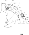
- FIG. 1 schematically shows a top view of an ego vehicle 1 arranged to run at an ego vehicle velocity v on a road 2 in a forward over-ground movement direction F, in the following referred to as ego direction F, where the ego vehicle 1 comprises a vehicle radar system 3.
- the vehicle radar system 3 comprises a radar sensor arrangement 4 that is arranged to distinguish and/or resolve single targets from the surroundings by transmitting signals 6 and receiving reflected signals 7 and using a Doppler effect in a previously well-known manner.
- the vehicle radar system 3 further comprises a main control unit 8 that is connected to the radar sensor arrangement 4 and is arranged to provide radial velocity and azimuth angles of possible target objects 5 by simultaneously sampling and analyzing phase and amplitude of the received signals 7.
- the reflected signals 7 correspond to radar detections, where the main control unit 8 comprises a tracking function that is arranged to group these radar detections as tracked objects, providing a common motion state for an extended detected object.
- the ego vehicle 1 has a center of mass 10 and an angular rotational velocity ⁇ ego . around the center of mass 10, and the radar sensor arrangements 4 has a certain relation to the center of mass 10.
- a yaw sensor device 20 is connected to the main control unit 8.
- the radar sensor arrangement is positioned in the origin of a corresponding coordinate system 11, and is positioned at a distance y sen along a y-axis of the coordinate system 11 from the center of mass 10, and at a distance x sen along an x-axis of the coordinate system 11 from the center of mass 10.
- the ego vehicle 1 runs in the ego direction F on the road 2, and the vehicle radar system 3 tracks a detected object in the form of an oncoming vehicle 9.
- v relx , v rely is the detected relative velocity of the oncoming vehicle 9
- v egoX is the movement of the radar sensor arrangement 4 resulting from the center of mass 10 of the ego vehicle 1
- y sen . ⁇ ego . , x sen ⁇ ⁇ ego . is the movement of the radar sensor arrangement 4 resulting from a rotational movement around the center of mass 10.
- the measured oncome direction 13 and the ego direction F' are shifted to correspond with that the vehicles 1, 9 are positioned on a common curve 12 with a certain curve radius R.
- the center of mass 10 of the ego vehicle 1 is shifted to an adjusted center of mass 10' and the oncoming vehicle 9 is shifted to an adjusted detected oncoming position 14' which both are positioned on the common curve 12. This does not affect the oncome angle ⁇ track .
- the main control unit 8 is arranged to determine whether the ego vehicle 1 travels in a curve 17 by detecting if the angular rotational velocity ⁇ ego . exceeds a certain threshold, according to some aspects 2 deg/s. If that is the case, the main control unit 8 is arranged to determine a calculated oncome direction 13' that the oncoming vehicle 9 would have if it is moving along the common curve 12. The calculated oncome direction 13' corresponds to a direction the ego vehicle 1 would follow when it had travelled to the position of the oncoming vehicle 9 along the common curve 12.
- the calculated oncome direction 13' has a certain calculated oncome angle ⁇ relative the ego direction F" in the position of the oncoming vehicle 9, and the calculated oncome angle ⁇ is thus the angle that the ego direction F would be shifted when the ego vehicle 1 has travelled to the position of the oncoming vehicle 9 along the common curve 12.
- the main control unit 8 is then arranged to calculate a difference angle ⁇ between the measured oncome direction 13 and the calculated oncome direction 13' such that it can be established how much the oncome direction 13 differ from the calculated oncome direction 13' that corresponds to if the oncoming vehicle is moving on the same common curve 12 as the ego vehicle 1.
- the difference angle ⁇ thus constitutes a difference between the oncome angle ⁇ track and the calculated oncome angle ⁇ . If the difference angle ⁇ exceeds a certain threshold angle ⁇ max , the oncoming vehicle 9 is determined to be crossing.
- the oncome angle ⁇ track equals the calculated oncome angle ⁇ , such that the difference angle ⁇ equals zero.
- both vehicles 1, 9 move in the common curve 12.
- the oncoming vehicle 9 In order to determine whether the oncoming vehicle 9 should be determined to be crossing or not, i.e. whether the difference angle ⁇ exceeds a threshold or not. If the oncoming vehicle 9 is determined to be crossing, suitable safety measure are taken; for example emergency braking, emergency steering and pushing vehicle occupants towards the middle of the ego vehicle 1, suitably by means of one or more airbags.
- the threshold angle ⁇ max is adaptive, such that in straight driving situations, a first threshold angle ⁇ max1 is used, and in curves a second threshold angle ⁇ max2 is used, where the second threshold angle ⁇ max2 exceeds the first threshold angle ⁇ max1 .
- the first threshold angle ⁇ max1 is about 35°
- the second threshold angle ⁇ max2 is about 45°.
- the main control unit 8 is arranged to determine whether the ego vehicle 1 travels in a curve or not by detecting if the angular rotational velocity ⁇ ego . exceeds a certain threshold ⁇ egomax . , according to some aspects 2 deg/s, as mentioned previously. According to some aspects, If ⁇ ego . ⁇ ⁇ egomax .
- the threshold angle ⁇ max is step-wise reduced to the first threshold angle ⁇ max1 .
- Each subsequent step-wise change is according to some aspects performed for each subsequent radar cycle.
- a radar cycle is one observation phase during which the vehicle radar system 3 is arranged to acquire data, process said data on several signal processing levels and to send out available results.
- This can be a fixed time interval, or it can be a dynamic time interval depending on environment conditions and processing load.
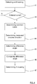
- the present disclosure also relates to a method for detecting oncoming vehicles relative an ego vehicle (1), where the method comprises:
- the method further comprises:
- the method comprises applying one or more safety measures.
- the vehicle radar system 3 is comprised in a vehicle environment detection system 40.
- the present disclosure is related to a vehicle environment detection system 40 arranged for any suitable environment detection technology, for example radar as in the examples above, but also Lidar (Light detection and ranging) and/or image detection are conceivable.
- the yaw sensor device 20 is comprised in the vehicle environment detection system 40.
- the vehicle environment detection system 40 generally comprises one or more environment detection sensor arrangements 4.
- the main control unit 8 comprises one or more control unit parts which according to some aspects are combined, adjacent or distributed. One or more of such control unit parts are according to some aspects comprised in the vehicle environment detection system 40.
- any suitable reference point on the ego vehicle 1 can be used and adjusted to lie on the common curve 12.
- the orientation of the coordinates and the coordinate system may have many suitable configurations, generally there is a predetermined axis with reference to which the ego direction F is determined.
- the present disclosure relates to a vehicle environment detection system 40 adapted to be mounted in an ego vehicle 1 and comprising at least one vehicle environment sensor arrangement 4 and a main control unit 8, where the vehicle environment detection system 40 is arranged to detect and track at least one oncoming vehicle 9, where the vehicle environment detection system 40 is arranged to determine whether the ego vehicle 1 has entered a curve 17.
- the main control unit 8 is arranged to:
- the main control unit 8 is arranged to apply one or more safety measures.
- the vehicle environment detection system 40 comprises a yaw sensor device 20 that is connected to the main control unit 8 and is arranged to enable the main control unit 8 to determine an ego direction F along which the ego vehicle 1 travels and to determine whether the ego vehicle 1 has entered a curve 17.
- said reference point 10' is an adjusted center of mass 10 of the ego vehicle 1, and that the angular rotational velocity ⁇ ego . is defined around said center of mass 10.
- the threshold angle ⁇ max is step-wise reduced to the first threshold angle ⁇ max1 .
- the vehicle environment detection system 40 comprises at least one of a radar system 3, a Lidar (Light detection and ranging) system and/or an image detection system.
- the present disclosure also relates to a method for detecting oncoming vehicles relative an ego vehicle 1, where the method comprises:
- the method further comprises:
- the method comprises applying one or more safety measures.
- the method comprises:
- said reference point 10' is an adjusted center of mass 10 of the ego vehicle 1, and that the angular rotational velocity ⁇ ego . is defined around said center of mass 10.
- the method comprises step-wise reducing the threshold angle ⁇ max to the first threshold angle ⁇ max1 .
Landscapes
- Engineering & Computer Science (AREA)
- Mechanical Engineering (AREA)
- Automation & Control Theory (AREA)
- Transportation (AREA)
- Physics & Mathematics (AREA)
- Mathematical Physics (AREA)
- Remote Sensing (AREA)
- Radar, Positioning & Navigation (AREA)
- Electromagnetism (AREA)
- Computer Networks & Wireless Communication (AREA)
- General Physics & Mathematics (AREA)
- Traffic Control Systems (AREA)
- Radar Systems Or Details Thereof (AREA)
Claims (14)
- Fahrzeugumgebungsdetektionssystem (40), das ausgebildet ist, um in einem Ego-Fahrzeug (1) montiert zu werden, und mindestens eine Fahrzeugumgebungssensoranordnung (4) und ein Hauptsteuergerät (8) umfasst, wobei das Fahrzeugumgebungsdetektionssystem (40) ausgelegt ist, um mindestens ein entgegenkommendes Fahrzeug (9) zu detektieren und zu verfolgen, wobei das Fahrzeugumgebungsdetektionssystem (40) ausgelegt ist, um festzustellen, ob das Ego-Fahrzeug (1) in eine Kurve (17) eingefahren ist, dadurch gekennzeichnet, dass, wenn das Fahrzeugumgebungsdetektionssystem (40) festgestellt hat, dass das Ego-Fahrzeug (1) in eine Kurve (17) eingefahren ist, bei jedem verfolgten entgegenkommenden Fahrzeug (9), das Hauptsteuergerät (8) ausgelegt ist zum:- Feststellen einer gemeinsamen Kurve (12) mit einem Radius (R), entlang welcher gemeinsamen Kurve (12) das Ego-Fahrzeug (1) voraussichtlich fährt;- Feststellen einer gemessenen entgegenkommenden Richtung (13, 13') des verfolgten entgegenkommenden Fahrzeugs (9) auf der gemeinsamen Kurve (16), entsprechend einem entgegenkommenden Winkel (θtrack) mit Bezug auf eine vorbestimmte Achse (x);- Feststellen eines Differenzwinkels (δ) zwischen der gemessenen entgegenkommenden Richtung (13, 13') und einer entgegenkommenden Richtung (13) entsprechend dem, wenn sich das entgegenkommende Fahrzeug (9) entlang der gemeinsamen Kurve (12) bewegen würde;- Vergleichen des Differenzwinkels (δ) mit einem Schwellwertwinkel (θmax); und- Feststellen des Überschneidens des entgegenkommenden Fahrzeugs (9), wenn festgestellt wurde, dass der Differenzwinkel (δ) den Schwellwertwinkel (θmax) übersteigt.
- Fahrzeugumgebungsdetektionssystem (40) nach Anspruch 1, dadurch gekennzeichnet, dass bei jedem verfolgten entgegenkommenden Fahrzeug (9), dessen Überschneiden festgestellt wurde, vorgesehen ist, dass das Hauptsteuergerät (8) eine oder mehrere Sicherheitsmaßnahmen anwendet.
- Fahrzeugumgebungsdetektionssystem (40) nach einem der Ansprüche 1 oder 2, dadurch gekennzeichnet, dass das Fahrzeugumgebungsdetektionssystem (40) eine Giersensorvorrichtung (20) umfasst, die mit dem Hauptsteuergerät (8) verbunden und ausgelegt ist, um dem Hauptsteuergerät (8) zu ermöglichen, eine Ego-Richtung (F) festzustellen, entlang welcher das Ego-Fahrzeug (1) fährt, und festzustellen, ob das Ego-Fahrzeug (1) in eine Kurve (17) eingefahren ist.
- Fahrzeugumgebungsdetektionssystem (40) nach einem der vorhergehenden Ansprüche, dadurch gekennzeichnet, dass das Hauptsteuergerät (8) ausgelegt ist, um den Differenzwinkel (δ) gemäß δ = θtrack - α zu berechnen, wobei θtrack der entgegenkommende Winkel ist und α ein berechneter entgegenkommender Winkel entsprechend dem ist, wenn sich das entgegenkommende Fahrzeug (9) entlang der gemeinsamen Kurve (12) bewegen würde, wobei das Hauptsteuergerät (8) ausgelegt ist zum Berechnen des berechneten entgegenkommenden Winkels (α) gemäß


- Fahrzeugumgebungsdetektionssystem (40) nach Anspruch 4, dadurch gekennzeichnet, dass der Referenzpunkt (10') ein eingestellter Massenmittelpunkt (10) des Ego-Fahrzeugs (1) ist und dass die Drehwinkelgeschwindigkeit

- Fahrzeugumgebungsdetektionssystem (40) nach einem der vorhergehenden Ansprüche, dadurch gekennzeichnet, dass, wenn das Fahrzeugumgebungsdetektionssystem (40) festgestellt hat, dass das Ego-Fahrzeug (1) in eine Kurve (17) eingefahren ist, das Hauptsteuergerät (8) ausgelegt ist, um den Schwellwertwinkel (θmax) schrittweise von einem ersten Schwellwertwinkel (θmax1) auf einen zweiten Schwellwertwinkel (θmax2) zu erhöhen, wobei dies schrittweise erfolgt gemäß:


- Fahrzeugumgebungsdetektionssystem (40) nach Anspruch 6, dadurch gekennzeichnet, dass, wenn das Fahrzeugumgebungsdetektionssystem (40) festgestellt hat, dass das Ego-Fahrzeug (1) die Kurve (17) verlassen hat, der Schwellwertwinkel (θmax) schrittweise auf den ersten Schwellwertwinkel (θmax1) verringert wird.
- Fahrzeugumgebungsdetektionssystem (40) nach einem der vorhergehenden Ansprüche, dadurch gekennzeichnet, dass das Fahrzeugumgebungsdetektionssystem (40) mindestens eines von einem Radarsystem (3), einem LIDAR(Light Detection and Ranging)-System und/oder einem Bilddetektionssystem umfasst.
- Verfahren zur Detektion entgegenkommender Fahrzeuge relativ zu einem Ego-Fahrzeug (1), wobei das Verfahren umfasst:(41) Detektieren und Verfolgen mindestens eines entgegenkommenden Fahrzeugs (9); und(42) Feststellen, ob das Ego-Fahrzeug (1) in eine Kurve (17) eingefahren ist,dadurch gekennzeichnet, dass, wenn festgestellt wurde, dass das Ego-Fahrzeug (1) in eine Kurve (17) eingefahren ist, bei jedem verfolgten entgegenkommenden Fahrzeug (9), das Verfahren ferner umfasst:(43) Feststellen einer gemeinsamen Kurve (12) mit einem Radius (R), entlang welcher gemeinsamen Kurve (12) das Ego-Fahrzeug (1) voraussichtlich fährt;(44) Feststellen einer gemessenen entgegenkommenden Richtung (13, 13') des verfolgten entgegenkommenden Fahrzeugs (9) auf der gemeinsamen Kurve (16), entsprechend einem entgegenkommenden Winkel (θtrack) mit Bezug auf eine vorbestimmte Achse (x);(45) Feststellen eines Differenzwinkels (δ) zwischen der gemessenen entgegenkommenden Richtung (13, 13') und einer entgegenkommenden Richtung (13) entsprechend dem, wenn sich das entgegenkommende Fahrzeug (9) entlang der gemeinsamen Kurve (12) bewegen würde;(46) Vergleichen des Differenzwinkels (δ) mit einem Schwellwertwinkel (θmax); und(47) Feststellen des Überschneidens des entgegenkommenden Fahrzeugs, wenn festgestellt wurde, dass der Differenzwinkel (δ) den Schwellwertwinkel (θmax) übersteigt.
- Verfahren nach Anspruch 9, dadurch gekennzeichnet, dass bei jedem verfolgten entgegenkommenden Fahrzeug (9), dessen Überschneiden festgestellt wurde, das Verfahren das Anwenden einer oder mehrerer Sicherheitsmaßnahmen umfasst.
- Verfahren nach einem der Ansprüche 9 oder 10, dadurch gekennzeichnet, dass das Verfahren umfasst:Berechnen des Differenzwinkels (δ) gemäß δ = θtrack - α, wobei θtrack der entgegenkommende Winkel ist und α ein berechneter entgegenkommender Winkel entsprechend dem ist, wenn sich das entgegenkommende Fahrzeug (9) entlang der gemeinsamen Kurve (12) bewegen würde; undBerechnen des berechneten entgegenkommenden Winkels (α) gemäß


- Verfahren nach Anspruch 11, dadurch gekennzeichnet, dass der Referenzpunkt (10') ein eingestellter Massenmittelpunkt (10) des Ego-Fahrzeugs (1) ist und dass die Drehwinkelgeschwindigkeit

- Verfahren nach einem der Ansprüche 9-12, dadurch gekennzeichnet, dass, wenn festgestellt wurde, dass das Ego-Fahrzeug (1) in eine Kurve (17) eingefahren ist, das Verfahren das Erhöhen des Schwellwertwinkels (θmax) schrittweise von einem ersten Schwellwertwinkel (θmax1) zu einem zweiten Schwellwertwinkel (θmax2) umfasst, wobei dies schrittweise erfolgt gemäß:


- Verfahren nach Anspruch 13, dadurch gekennzeichnet, dass, wenn festgestellt wurde, dass das Ego-Fahrzeug (1) die Kurve (17) verlassen hat, das Verfahren das schrittweise Verringern des Schwellwertwinkels (θmax) auf den ersten Schwellwertwinkel (θmax1) umfasst.
Priority Applications (5)
| Application Number | Priority Date | Filing Date | Title |
|---|---|---|---|
| EP17175128.2A EP3413082B1 (de) | 2017-06-09 | 2017-06-09 | Fahrzeugsystem zur detektion von entgegenkommenden fahrzeugen |
| PCT/EP2018/064762 WO2018224495A1 (en) | 2017-06-09 | 2018-06-05 | A vehicle system for detection of oncoming vehicles |
| US16/620,051 US11433900B2 (en) | 2017-06-09 | 2018-06-05 | Vehicle system for detection of oncoming vehicles |
| CN201880034793.5A CN110678778B (zh) | 2017-06-09 | 2018-06-05 | 用于检测迎面车辆的车辆系统 |
| US17/861,632 US12024175B2 (en) | 2017-06-09 | 2022-07-11 | Vehicle system for detection of oncoming vehicles |
Applications Claiming Priority (1)
| Application Number | Priority Date | Filing Date | Title |
|---|---|---|---|
| EP17175128.2A EP3413082B1 (de) | 2017-06-09 | 2017-06-09 | Fahrzeugsystem zur detektion von entgegenkommenden fahrzeugen |
Publications (2)
| Publication Number | Publication Date |
|---|---|
| EP3413082A1 EP3413082A1 (de) | 2018-12-12 |
| EP3413082B1 true EP3413082B1 (de) | 2020-01-01 |
Family
ID=59034554
Family Applications (1)
| Application Number | Title | Priority Date | Filing Date |
|---|---|---|---|
| EP17175128.2A Active EP3413082B1 (de) | 2017-06-09 | 2017-06-09 | Fahrzeugsystem zur detektion von entgegenkommenden fahrzeugen |
Country Status (4)
| Country | Link |
|---|---|
| US (2) | US11433900B2 (de) |
| EP (1) | EP3413082B1 (de) |
| CN (1) | CN110678778B (de) |
| WO (1) | WO2018224495A1 (de) |
Families Citing this family (2)
| Publication number | Priority date | Publication date | Assignee | Title |
|---|---|---|---|---|
| EP3413083B1 (de) * | 2017-06-09 | 2020-03-11 | Veoneer Sweden AB | Fahrzeugsystem zur detektion von entgegenkommenden fahrzeugen |
| EP3413082B1 (de) | 2017-06-09 | 2020-01-01 | Veoneer Sweden AB | Fahrzeugsystem zur detektion von entgegenkommenden fahrzeugen |
Family Cites Families (57)
| Publication number | Priority date | Publication date | Assignee | Title |
|---|---|---|---|---|
| US6822563B2 (en) * | 1997-09-22 | 2004-11-23 | Donnelly Corporation | Vehicle imaging system with accessory control |
| DE19736965C1 (de) * | 1997-08-25 | 1999-05-06 | Mannesmann Vdo Ag | Verfahren und Anordnung zur Überprüfung der Gierrate eines sich bewegenden Objektes |
| JP3658519B2 (ja) * | 1999-06-28 | 2005-06-08 | 株式会社日立製作所 | 自動車の制御システムおよび自動車の制御装置 |
| US7522091B2 (en) * | 2002-07-15 | 2009-04-21 | Automotive Systems Laboratory, Inc. | Road curvature estimation system |
| DE10254423A1 (de) * | 2002-11-21 | 2004-06-03 | Lucas Automotive Gmbh | System zur Beeinflussung der Geschwindigkeit eines Kraftfahrzeuges |
| JP4421450B2 (ja) * | 2004-11-22 | 2010-02-24 | 本田技研工業株式会社 | 車両の逸脱判定装置 |
| JP2006267005A (ja) * | 2005-03-25 | 2006-10-05 | Xanavi Informatics Corp | 現在位置算出装置及び位置情報算出方法 |
| JP4169065B2 (ja) * | 2006-02-13 | 2008-10-22 | 株式会社デンソー | 車両制御装置 |
| JP4862036B2 (ja) * | 2006-03-06 | 2012-01-25 | 日立オートモティブシステムズ株式会社 | 自動車の制御装置及び制御方法 |
| JP5038986B2 (ja) * | 2008-07-04 | 2012-10-03 | トヨタ自動車株式会社 | 衝突予測装置 |
| WO2010073292A1 (ja) * | 2008-12-22 | 2010-07-01 | トヨタ自動車株式会社 | レーダ装置、及び当該レーダ装置において用いられる測定方法 |
| JP5310674B2 (ja) * | 2010-08-17 | 2013-10-09 | 株式会社デンソー | 車両用挙動制御装置 |
| JP5376187B2 (ja) | 2010-09-24 | 2013-12-25 | トヨタ自動車株式会社 | 物体検出装置及び物体検出プログラム |
| US9415718B2 (en) * | 2011-06-08 | 2016-08-16 | Denso Corporation | Vehicular headlight apparatus |
| EP2750118B1 (de) * | 2011-08-26 | 2020-01-01 | Toyota Jidosha Kabushiki Kaisha | Antriebshilfsvorrichtung und antriebshilfsverfahren |
| JP5760884B2 (ja) * | 2011-09-09 | 2015-08-12 | 株式会社デンソー | 車両の旋回予測装置 |
| US9321329B2 (en) * | 2012-05-10 | 2016-04-26 | Chris Beckman | Glare elimination and image enhancement system improving lenses, windows and displays |
| CN104487309B (zh) * | 2012-07-24 | 2017-03-08 | 丰田自动车株式会社 | 驾驶辅助装置 |
| JP6183799B2 (ja) * | 2013-06-14 | 2017-08-23 | 日立オートモティブシステムズ株式会社 | 車両制御システム |
| DE102013211651A1 (de) * | 2013-06-20 | 2014-12-24 | Robert Bosch Gmbh | Verfahren und Vorrichtung zur Vermeidung einer möglichen Folgekollision bzw. zur Verringerung der Unfallfolgen einer Kollision |
| WO2015005377A1 (ja) * | 2013-07-11 | 2015-01-15 | 株式会社小糸製作所 | 車両用前照灯の配光制御方法および配光制御装置 |
| JP2015033944A (ja) * | 2013-08-09 | 2015-02-19 | スタンレー電気株式会社 | 車両用前照灯の点灯制御装置、車両用前照灯システム |
| US9738222B2 (en) * | 2013-09-28 | 2017-08-22 | Oldcastle Materials, Inc. | Advanced warning and risk evasion system and method |
| EP3057848B1 (de) * | 2013-10-16 | 2018-04-11 | Sentient AB | Verfahren zur steuerung des fahrzeugverhaltens |
| US9988047B2 (en) * | 2013-12-12 | 2018-06-05 | Magna Electronics Inc. | Vehicle control system with traffic driving control |
| DE112014006561T5 (de) * | 2014-04-10 | 2017-02-16 | Mitsubishi Electric Corporation | Routenvorausberechunungseinrichtung |
| JP5969534B2 (ja) * | 2014-04-21 | 2016-08-17 | 株式会社デンソー | 走行支援装置 |
| JP2016001170A (ja) * | 2014-05-19 | 2016-01-07 | 株式会社リコー | 処理装置、処理プログラム、及び、処理方法 |
| JP2016001464A (ja) * | 2014-05-19 | 2016-01-07 | 株式会社リコー | 処理装置、処理システム、処理プログラム、及び、処理方法 |
| CN113158820B (zh) * | 2014-08-18 | 2024-07-16 | 无比视视觉技术有限公司 | 在导航中对车道限制和施工区域的识别和预测 |
| US9482751B2 (en) * | 2014-10-13 | 2016-11-01 | Applied Concepts, Inc. | Collision detection system and method of operation |
| JP5880904B1 (ja) * | 2014-11-20 | 2016-03-09 | パナソニックIpマネジメント株式会社 | 端末装置 |
| JP6246392B2 (ja) * | 2014-12-09 | 2017-12-13 | 三菱電機株式会社 | 衝突リスク算出装置、衝突リスク表示装置、車体制御装置 |
| JP5979259B2 (ja) * | 2015-01-20 | 2016-08-24 | トヨタ自動車株式会社 | 衝突回避制御装置 |
| JP6376348B2 (ja) * | 2015-02-20 | 2018-08-22 | ウシオ電機株式会社 | 車両運転支援装置 |
| EP4030378A1 (de) * | 2015-05-10 | 2022-07-20 | Mobileye Vision Technologies Ltd. | Strassenprofile entlang eines prognostizierten weges |
| GB2541354A (en) * | 2015-05-27 | 2017-02-22 | Cambridge Entpr Ltd | Collision avoidance method, computer program product for said collision avoidance method and collision avoidance system |
| EP3106836B1 (de) * | 2015-06-16 | 2018-06-06 | Volvo Car Corporation | Einheit und verfahren zur einstellung einer strassenbegrenzung |
| US10214206B2 (en) * | 2015-07-13 | 2019-02-26 | Magna Electronics Inc. | Parking assist system for vehicle |
| US9751506B2 (en) * | 2015-10-27 | 2017-09-05 | GM Global Technology Operations LLC | Algorithms for avoiding automotive crashes at left and right turn intersections |
| US9688273B2 (en) * | 2015-10-27 | 2017-06-27 | GM Global Technology Operations LLC | Methods of improving performance of automotive intersection turn assist features |
| JP6473685B2 (ja) * | 2015-11-19 | 2019-02-20 | 日立建機株式会社 | 車両制御装置及び作業機械 |
| DE102015224171A1 (de) * | 2015-12-03 | 2017-06-08 | Robert Bosch Gmbh | Neigungserkennung bei Zweirädern |
| CN106355890B (zh) * | 2016-09-27 | 2019-03-05 | 东软集团股份有限公司 | 一种对目标车辆分类的判断方法及装置 |
| US10416304B2 (en) * | 2017-03-06 | 2019-09-17 | The Aerospace Corporation | Automobile accident mitigation technique |
| EP3413082B1 (de) * | 2017-06-09 | 2020-01-01 | Veoneer Sweden AB | Fahrzeugsystem zur detektion von entgegenkommenden fahrzeugen |
| EP3413083B1 (de) * | 2017-06-09 | 2020-03-11 | Veoneer Sweden AB | Fahrzeugsystem zur detektion von entgegenkommenden fahrzeugen |
| DE102018210280A1 (de) * | 2018-06-25 | 2020-01-02 | Robert Bosch Gmbh | Anpassung der Trajektorie eines Ego-Fahrzeugs an bewegte Fremdobjekte |
| EP3626582B1 (de) * | 2018-09-18 | 2023-08-09 | Volvo Car Corporation | Verfahren und system zur kollisionsvermeidung |
| DE102019202592A1 (de) * | 2019-02-26 | 2020-08-27 | Volkswagen Aktiengesellschaft | Verfahren zum Betreiben eines Fahrerinformationssystems in einem Ego-Fahrzeug und Fahrerinformationssystem |
| DE102019202591A1 (de) * | 2019-02-26 | 2020-08-27 | Volkswagen Aktiengesellschaft | Verfahren zum Betreiben eines Fahrerinformationssystems in einem Ego-Fahrzeug und Fahrerinformationssystem |
| DE102019215147A1 (de) * | 2019-10-01 | 2021-04-01 | Continental Automotive Gmbh | Verfahren und Fahrerassistenzvorrichtung zur Führung eines Ego-Fahrzeugs |
| US11635763B2 (en) * | 2020-02-28 | 2023-04-25 | Nissan North America, Inc. | 3D occlusion reasoning for accident avoidance |
| FR3120039B1 (fr) * | 2021-02-19 | 2025-09-26 | Renault Sas | Procédé d’évitement d’obstacles |
| FR3120040B1 (fr) * | 2021-02-19 | 2023-02-24 | Renault Sas | Procédé d’activation d’un système d’évitement d’obstacle pour véhicule automobile |
| US20220283587A1 (en) * | 2021-03-02 | 2022-09-08 | Motional Ad Llc | Controlling an autonomous vehicle using a proximity rule |
| US11614537B2 (en) * | 2021-04-01 | 2023-03-28 | GM Cruise Holdings LLC. | Radar system for generating an on-demand distributed aperture by mechanical articulation |
-
2017
- 2017-06-09 EP EP17175128.2A patent/EP3413082B1/de active Active
-
2018
- 2018-06-05 US US16/620,051 patent/US11433900B2/en active Active
- 2018-06-05 WO PCT/EP2018/064762 patent/WO2018224495A1/en not_active Ceased
- 2018-06-05 CN CN201880034793.5A patent/CN110678778B/zh active Active
-
2022
- 2022-07-11 US US17/861,632 patent/US12024175B2/en active Active
Non-Patent Citations (1)
| Title |
|---|
| None * |
Also Published As
| Publication number | Publication date |
|---|---|
| EP3413082A1 (de) | 2018-12-12 |
| CN110678778A (zh) | 2020-01-10 |
| WO2018224495A1 (en) | 2018-12-13 |
| US20220348209A1 (en) | 2022-11-03 |
| US20200198640A1 (en) | 2020-06-25 |
| CN110678778B (zh) | 2023-05-19 |
| US11433900B2 (en) | 2022-09-06 |
| US12024175B2 (en) | 2024-07-02 |
Similar Documents
| Publication | Publication Date | Title |
|---|---|---|
| US8112223B2 (en) | Method for measuring lateral movements in a driver assistance system | |
| US11046312B2 (en) | Vehicle travel support device | |
| JP3658519B2 (ja) | 自動車の制御システムおよび自動車の制御装置 | |
| US9886858B2 (en) | Lane change detection | |
| EP3176603B1 (de) | Fahrzeugradarsystem | |
| JP7028982B2 (ja) | レーダ処理装置 | |
| EP3293545A1 (de) | Bestimmung der relativen geschwindigkeit in einem kraftfahrzeugradarsystem | |
| JP2007317018A (ja) | 衝突判定装置 | |
| EP2100164B1 (de) | Vorrichtung zur umgebungsüberwachung eines kfz | |
| US12024175B2 (en) | Vehicle system for detection of oncoming vehicles | |
| JP2002175599A (ja) | 先行車または物標の車線位置推定装置 | |
| EP3413083B1 (de) | Fahrzeugsystem zur detektion von entgegenkommenden fahrzeugen | |
| US20050004719A1 (en) | Device and method for determining the position of objects in the surroundings of a motor vehicle | |
| JP3719691B2 (ja) | 車両認識装置 | |
| JP5178652B2 (ja) | 車両の走行安全装置 | |
| EP3422045A1 (de) | System zur verbesserten objektverfolgung | |
| US20250347776A1 (en) | Object recognition apparatus and method | |
| Jansson et al. | A probabilistic approach to collision risk estimation for passenger vehicles |
Legal Events
| Date | Code | Title | Description |
|---|---|---|---|
| PUAI | Public reference made under article 153(3) epc to a published international application that has entered the european phase |
Free format text: ORIGINAL CODE: 0009012 |
|
| STAA | Information on the status of an ep patent application or granted ep patent |
Free format text: STATUS: THE APPLICATION HAS BEEN PUBLISHED |
|
| AK | Designated contracting states |
Kind code of ref document: A1 Designated state(s): AL AT BE BG CH CY CZ DE DK EE ES FI FR GB GR HR HU IE IS IT LI LT LU LV MC MK MT NL NO PL PT RO RS SE SI SK SM TR |
|
| AX | Request for extension of the european patent |
Extension state: BA ME |
|
| STAA | Information on the status of an ep patent application or granted ep patent |
Free format text: STATUS: REQUEST FOR EXAMINATION WAS MADE |
|
| 17P | Request for examination filed |
Effective date: 20190611 |
|
| RBV | Designated contracting states (corrected) |
Designated state(s): AL AT BE BG CH CY CZ DE DK EE ES FI FR GB GR HR HU IE IS IT LI LT LU LV MC MK MT NL NO PL PT RO RS SE SI SK SM TR |
|
| GRAP | Despatch of communication of intention to grant a patent |
Free format text: ORIGINAL CODE: EPIDOSNIGR1 |
|
| STAA | Information on the status of an ep patent application or granted ep patent |
Free format text: STATUS: GRANT OF PATENT IS INTENDED |
|
| RIC1 | Information provided on ipc code assigned before grant |
Ipc: G01S 13/93 20060101AFI20190701BHEP Ipc: G01S 17/93 20060101ALN20190701BHEP Ipc: B60W 30/095 20120101ALI20190701BHEP |
|
| INTG | Intention to grant announced |
Effective date: 20190729 |
|
| GRAS | Grant fee paid |
Free format text: ORIGINAL CODE: EPIDOSNIGR3 |
|
| GRAA | (expected) grant |
Free format text: ORIGINAL CODE: 0009210 |
|
| STAA | Information on the status of an ep patent application or granted ep patent |
Free format text: STATUS: THE PATENT HAS BEEN GRANTED |
|
| AK | Designated contracting states |
Kind code of ref document: B1 Designated state(s): AL AT BE BG CH CY CZ DE DK EE ES FI FR GB GR HR HU IE IS IT LI LT LU LV MC MK MT NL NO PL PT RO RS SE SI SK SM TR |
|
| REG | Reference to a national code |
Ref country code: GB Ref legal event code: FG4D |
|
| REG | Reference to a national code |
Ref country code: CH Ref legal event code: EP Ref country code: AT Ref legal event code: REF Ref document number: 1220471 Country of ref document: AT Kind code of ref document: T Effective date: 20200115 |
|
| REG | Reference to a national code |
Ref country code: IE Ref legal event code: FG4D |
|
| REG | Reference to a national code |
Ref country code: DE Ref legal event code: R096 Ref document number: 602017010278 Country of ref document: DE |
|
| REG | Reference to a national code |
Ref country code: NL Ref legal event code: MP Effective date: 20200101 |
|
| REG | Reference to a national code |
Ref country code: LT Ref legal event code: MG4D |
|
| PG25 | Lapsed in a contracting state [announced via postgrant information from national office to epo] |
Ref country code: FI Free format text: LAPSE BECAUSE OF FAILURE TO SUBMIT A TRANSLATION OF THE DESCRIPTION OR TO PAY THE FEE WITHIN THE PRESCRIBED TIME-LIMIT Effective date: 20200101 Ref country code: NO Free format text: LAPSE BECAUSE OF FAILURE TO SUBMIT A TRANSLATION OF THE DESCRIPTION OR TO PAY THE FEE WITHIN THE PRESCRIBED TIME-LIMIT Effective date: 20200401 Ref country code: PT Free format text: LAPSE BECAUSE OF FAILURE TO SUBMIT A TRANSLATION OF THE DESCRIPTION OR TO PAY THE FEE WITHIN THE PRESCRIBED TIME-LIMIT Effective date: 20200527 Ref country code: CZ Free format text: LAPSE BECAUSE OF FAILURE TO SUBMIT A TRANSLATION OF THE DESCRIPTION OR TO PAY THE FEE WITHIN THE PRESCRIBED TIME-LIMIT Effective date: 20200101 Ref country code: LT Free format text: LAPSE BECAUSE OF FAILURE TO SUBMIT A TRANSLATION OF THE DESCRIPTION OR TO PAY THE FEE WITHIN THE PRESCRIBED TIME-LIMIT Effective date: 20200101 Ref country code: NL Free format text: LAPSE BECAUSE OF FAILURE TO SUBMIT A TRANSLATION OF THE DESCRIPTION OR TO PAY THE FEE WITHIN THE PRESCRIBED TIME-LIMIT Effective date: 20200101 Ref country code: RS Free format text: LAPSE BECAUSE OF FAILURE TO SUBMIT A TRANSLATION OF THE DESCRIPTION OR TO PAY THE FEE WITHIN THE PRESCRIBED TIME-LIMIT Effective date: 20200101 |
|
| PG25 | Lapsed in a contracting state [announced via postgrant information from national office to epo] |
Ref country code: BG Free format text: LAPSE BECAUSE OF FAILURE TO SUBMIT A TRANSLATION OF THE DESCRIPTION OR TO PAY THE FEE WITHIN THE PRESCRIBED TIME-LIMIT Effective date: 20200401 Ref country code: IS Free format text: LAPSE BECAUSE OF FAILURE TO SUBMIT A TRANSLATION OF THE DESCRIPTION OR TO PAY THE FEE WITHIN THE PRESCRIBED TIME-LIMIT Effective date: 20200501 Ref country code: LV Free format text: LAPSE BECAUSE OF FAILURE TO SUBMIT A TRANSLATION OF THE DESCRIPTION OR TO PAY THE FEE WITHIN THE PRESCRIBED TIME-LIMIT Effective date: 20200101 Ref country code: SE Free format text: LAPSE BECAUSE OF FAILURE TO SUBMIT A TRANSLATION OF THE DESCRIPTION OR TO PAY THE FEE WITHIN THE PRESCRIBED TIME-LIMIT Effective date: 20200101 Ref country code: GR Free format text: LAPSE BECAUSE OF FAILURE TO SUBMIT A TRANSLATION OF THE DESCRIPTION OR TO PAY THE FEE WITHIN THE PRESCRIBED TIME-LIMIT Effective date: 20200402 Ref country code: HR Free format text: LAPSE BECAUSE OF FAILURE TO SUBMIT A TRANSLATION OF THE DESCRIPTION OR TO PAY THE FEE WITHIN THE PRESCRIBED TIME-LIMIT Effective date: 20200101 |
|
| REG | Reference to a national code |
Ref country code: DE Ref legal event code: R097 Ref document number: 602017010278 Country of ref document: DE |
|
| PG25 | Lapsed in a contracting state [announced via postgrant information from national office to epo] |
Ref country code: RO Free format text: LAPSE BECAUSE OF FAILURE TO SUBMIT A TRANSLATION OF THE DESCRIPTION OR TO PAY THE FEE WITHIN THE PRESCRIBED TIME-LIMIT Effective date: 20200101 Ref country code: ES Free format text: LAPSE BECAUSE OF FAILURE TO SUBMIT A TRANSLATION OF THE DESCRIPTION OR TO PAY THE FEE WITHIN THE PRESCRIBED TIME-LIMIT Effective date: 20200101 Ref country code: SM Free format text: LAPSE BECAUSE OF FAILURE TO SUBMIT A TRANSLATION OF THE DESCRIPTION OR TO PAY THE FEE WITHIN THE PRESCRIBED TIME-LIMIT Effective date: 20200101 Ref country code: EE Free format text: LAPSE BECAUSE OF FAILURE TO SUBMIT A TRANSLATION OF THE DESCRIPTION OR TO PAY THE FEE WITHIN THE PRESCRIBED TIME-LIMIT Effective date: 20200101 Ref country code: SK Free format text: LAPSE BECAUSE OF FAILURE TO SUBMIT A TRANSLATION OF THE DESCRIPTION OR TO PAY THE FEE WITHIN THE PRESCRIBED TIME-LIMIT Effective date: 20200101 Ref country code: DK Free format text: LAPSE BECAUSE OF FAILURE TO SUBMIT A TRANSLATION OF THE DESCRIPTION OR TO PAY THE FEE WITHIN THE PRESCRIBED TIME-LIMIT Effective date: 20200101 |
|
| PLBE | No opposition filed within time limit |
Free format text: ORIGINAL CODE: 0009261 |
|
| STAA | Information on the status of an ep patent application or granted ep patent |
Free format text: STATUS: NO OPPOSITION FILED WITHIN TIME LIMIT |
|
| REG | Reference to a national code |
Ref country code: AT Ref legal event code: MK05 Ref document number: 1220471 Country of ref document: AT Kind code of ref document: T Effective date: 20200101 |
|
| 26N | No opposition filed |
Effective date: 20201002 |
|
| PG25 | Lapsed in a contracting state [announced via postgrant information from national office to epo] |
Ref country code: MC Free format text: LAPSE BECAUSE OF FAILURE TO SUBMIT A TRANSLATION OF THE DESCRIPTION OR TO PAY THE FEE WITHIN THE PRESCRIBED TIME-LIMIT Effective date: 20200101 Ref country code: IT Free format text: LAPSE BECAUSE OF FAILURE TO SUBMIT A TRANSLATION OF THE DESCRIPTION OR TO PAY THE FEE WITHIN THE PRESCRIBED TIME-LIMIT Effective date: 20200101 Ref country code: AT Free format text: LAPSE BECAUSE OF FAILURE TO SUBMIT A TRANSLATION OF THE DESCRIPTION OR TO PAY THE FEE WITHIN THE PRESCRIBED TIME-LIMIT Effective date: 20200101 |
|
| REG | Reference to a national code |
Ref country code: CH Ref legal event code: PL |
|
| PG25 | Lapsed in a contracting state [announced via postgrant information from national office to epo] |
Ref country code: PL Free format text: LAPSE BECAUSE OF FAILURE TO SUBMIT A TRANSLATION OF THE DESCRIPTION OR TO PAY THE FEE WITHIN THE PRESCRIBED TIME-LIMIT Effective date: 20200101 Ref country code: SI Free format text: LAPSE BECAUSE OF FAILURE TO SUBMIT A TRANSLATION OF THE DESCRIPTION OR TO PAY THE FEE WITHIN THE PRESCRIBED TIME-LIMIT Effective date: 20200101 |
|
| PG25 | Lapsed in a contracting state [announced via postgrant information from national office to epo] |
Ref country code: LU Free format text: LAPSE BECAUSE OF NON-PAYMENT OF DUE FEES Effective date: 20200609 |
|
| REG | Reference to a national code |
Ref country code: BE Ref legal event code: MM Effective date: 20200630 |
|
| PG25 | Lapsed in a contracting state [announced via postgrant information from national office to epo] |
Ref country code: LI Free format text: LAPSE BECAUSE OF NON-PAYMENT OF DUE FEES Effective date: 20200630 Ref country code: CH Free format text: LAPSE BECAUSE OF NON-PAYMENT OF DUE FEES Effective date: 20200630 Ref country code: IE Free format text: LAPSE BECAUSE OF NON-PAYMENT OF DUE FEES Effective date: 20200609 |
|
| PG25 | Lapsed in a contracting state [announced via postgrant information from national office to epo] |
Ref country code: BE Free format text: LAPSE BECAUSE OF NON-PAYMENT OF DUE FEES Effective date: 20200630 |
|
| PG25 | Lapsed in a contracting state [announced via postgrant information from national office to epo] |
Ref country code: TR Free format text: LAPSE BECAUSE OF FAILURE TO SUBMIT A TRANSLATION OF THE DESCRIPTION OR TO PAY THE FEE WITHIN THE PRESCRIBED TIME-LIMIT Effective date: 20200101 Ref country code: MT Free format text: LAPSE BECAUSE OF FAILURE TO SUBMIT A TRANSLATION OF THE DESCRIPTION OR TO PAY THE FEE WITHIN THE PRESCRIBED TIME-LIMIT Effective date: 20200101 Ref country code: CY Free format text: LAPSE BECAUSE OF FAILURE TO SUBMIT A TRANSLATION OF THE DESCRIPTION OR TO PAY THE FEE WITHIN THE PRESCRIBED TIME-LIMIT Effective date: 20200101 |
|
| PG25 | Lapsed in a contracting state [announced via postgrant information from national office to epo] |
Ref country code: MK Free format text: LAPSE BECAUSE OF FAILURE TO SUBMIT A TRANSLATION OF THE DESCRIPTION OR TO PAY THE FEE WITHIN THE PRESCRIBED TIME-LIMIT Effective date: 20200101 Ref country code: AL Free format text: LAPSE BECAUSE OF FAILURE TO SUBMIT A TRANSLATION OF THE DESCRIPTION OR TO PAY THE FEE WITHIN THE PRESCRIBED TIME-LIMIT Effective date: 20200101 |
|
| REG | Reference to a national code |
Ref country code: DE Ref legal event code: R081 Ref document number: 602017010278 Country of ref document: DE Owner name: ARRIVER SOFTWARE AB, SE Free format text: FORMER OWNER: VEONEER SWEDEN AB, VARGARDA, SE Ref country code: DE Ref legal event code: R081 Ref document number: 602017010278 Country of ref document: DE Owner name: QUALCOMM AUTO LTD., GB Free format text: FORMER OWNER: VEONEER SWEDEN AB, VARGARDA, SE |
|
| REG | Reference to a national code |
Ref country code: GB Ref legal event code: 732E Free format text: REGISTERED BETWEEN 20241031 AND 20241106 |
|
| REG | Reference to a national code |
Ref country code: GB Ref legal event code: 732E Free format text: REGISTERED BETWEEN 20250206 AND 20250212 |
|
| REG | Reference to a national code |
Ref country code: DE Ref legal event code: R081 Ref document number: 602017010278 Country of ref document: DE Owner name: QUALCOMM AUTO LTD., GB Free format text: FORMER OWNER: ARRIVER SOFTWARE AB, LINKOEPING, SE |
|
| PGFP | Annual fee paid to national office [announced via postgrant information from national office to epo] |
Ref country code: DE Payment date: 20250509 Year of fee payment: 9 |
|
| PGFP | Annual fee paid to national office [announced via postgrant information from national office to epo] |
Ref country code: GB Payment date: 20250508 Year of fee payment: 9 |
|
| PGFP | Annual fee paid to national office [announced via postgrant information from national office to epo] |
Ref country code: FR Payment date: 20250512 Year of fee payment: 9 |