EP3413426B1 - Concentrateur - Google Patents
Concentrateur Download PDFInfo
- Publication number
- EP3413426B1 EP3413426B1 EP18176679.1A EP18176679A EP3413426B1 EP 3413426 B1 EP3413426 B1 EP 3413426B1 EP 18176679 A EP18176679 A EP 18176679A EP 3413426 B1 EP3413426 B1 EP 3413426B1
- Authority
- EP
- European Patent Office
- Prior art keywords
- power
- hub
- converter
- value
- measurement
- Prior art date
- Legal status (The legal status is an assumption and is not a legal conclusion. Google has not performed a legal analysis and makes no representation as to the accuracy of the status listed.)
- Active
Links
Images

Classifications
-
- H—ELECTRICITY
- H02—GENERATION; CONVERSION OR DISTRIBUTION OF ELECTRIC POWER
- H02J—ELECTRIC POWER NETWORKS; CIRCUIT ARRANGEMENTS OR SYSTEMS FOR SUPPLYING OR DISTRIBUTING ELECTRIC POWER; SYSTEMS FOR STORING ELECTRIC ENERGY
- H02J7/00—Circuit arrangements for charging or discharging batteries or for supplying loads from batteries
- H02J7/50—Circuit arrangements for charging or discharging batteries or for supplying loads from batteries acting upon multiple batteries simultaneously or sequentially
-
- G—PHYSICS
- G05—CONTROLLING; REGULATING
- G05B—CONTROL OR REGULATING SYSTEMS IN GENERAL; FUNCTIONAL ELEMENTS OF SUCH SYSTEMS; MONITORING OR TESTING ARRANGEMENTS FOR SUCH SYSTEMS OR ELEMENTS
- G05B19/00—Program-control systems
- G05B19/02—Program-control systems electric
- G05B19/04—Program control other than numerical control, i.e. in sequence controllers or logic controllers
- G05B19/042—Program control other than numerical control, i.e. in sequence controllers or logic controllers using digital processors
-
- G—PHYSICS
- G06—COMPUTING OR CALCULATING; COUNTING
- G06F—ELECTRIC DIGITAL DATA PROCESSING
- G06F1/00—Details not covered by groups G06F3/00 - G06F13/00 and G06F21/00
- G06F1/26—Power supply means, e.g. regulation thereof
- G06F1/266—Arrangements to supply power to external peripherals either directly from the computer or under computer control, e.g. supply of power through the communication port, computer controlled power-strips
-
- H—ELECTRICITY
- H01—ELECTRIC ELEMENTS
- H01R—ELECTRICALLY-CONDUCTIVE CONNECTIONS; STRUCTURAL ASSOCIATIONS OF A PLURALITY OF MUTUALLY-INSULATED ELECTRICAL CONNECTING ELEMENTS; COUPLING DEVICES; CURRENT COLLECTORS
- H01R27/00—Coupling parts adapted for co-operation with two or more dissimilar counterparts
- H01R27/02—Coupling parts adapted for co-operation with two or more dissimilar counterparts for simultaneous co-operation with two or more dissimilar counterparts
-
- H—ELECTRICITY
- H02—GENERATION; CONVERSION OR DISTRIBUTION OF ELECTRIC POWER
- H02J—ELECTRIC POWER NETWORKS; CIRCUIT ARRANGEMENTS OR SYSTEMS FOR SUPPLYING OR DISTRIBUTING ELECTRIC POWER; SYSTEMS FOR STORING ELECTRIC ENERGY
- H02J7/00—Circuit arrangements for charging or discharging batteries or for supplying loads from batteries
- H02J7/02—Circuit arrangements for charging or discharging batteries or for supplying loads from batteries for charging batteries from AC mains by converters
-
- H—ELECTRICITY
- H02—GENERATION; CONVERSION OR DISTRIBUTION OF ELECTRIC POWER
- H02J—ELECTRIC POWER NETWORKS; CIRCUIT ARRANGEMENTS OR SYSTEMS FOR SUPPLYING OR DISTRIBUTING ELECTRIC POWER; SYSTEMS FOR STORING ELECTRIC ENERGY
- H02J7/00—Circuit arrangements for charging or discharging batteries or for supplying loads from batteries
- H02J7/02—Circuit arrangements for charging or discharging batteries or for supplying loads from batteries for charging batteries from AC mains by converters
- H02J7/04—Regulation of charging current or voltage
-
- H—ELECTRICITY
- H02—GENERATION; CONVERSION OR DISTRIBUTION OF ELECTRIC POWER
- H02J—ELECTRIC POWER NETWORKS; CIRCUIT ARRANGEMENTS OR SYSTEMS FOR SUPPLYING OR DISTRIBUTING ELECTRIC POWER; SYSTEMS FOR STORING ELECTRIC ENERGY
- H02J7/00—Circuit arrangements for charging or discharging batteries or for supplying loads from batteries
- H02J7/02—Circuit arrangements for charging or discharging batteries or for supplying loads from batteries for charging batteries from AC mains by converters
- H02J7/04—Regulation of charging current or voltage
- H02J7/06—Regulation of charging current or voltage using discharge tubes or semiconductor devices
-
- H—ELECTRICITY
- H02—GENERATION; CONVERSION OR DISTRIBUTION OF ELECTRIC POWER
- H02J—ELECTRIC POWER NETWORKS; CIRCUIT ARRANGEMENTS OR SYSTEMS FOR SUPPLYING OR DISTRIBUTING ELECTRIC POWER; SYSTEMS FOR STORING ELECTRIC ENERGY
- H02J7/00—Circuit arrangements for charging or discharging batteries or for supplying loads from batteries
- H02J7/70—Circuit arrangements for charging or discharging batteries or for supplying loads from batteries characterised by the mechanical construction
-
- H—ELECTRICITY
- H02—GENERATION; CONVERSION OR DISTRIBUTION OF ELECTRIC POWER
- H02J—ELECTRIC POWER NETWORKS; CIRCUIT ARRANGEMENTS OR SYSTEMS FOR SUPPLYING OR DISTRIBUTING ELECTRIC POWER; SYSTEMS FOR STORING ELECTRIC ENERGY
- H02J7/00—Circuit arrangements for charging or discharging batteries or for supplying loads from batteries
- H02J7/90—Regulation of charging or discharging current or voltage
- H02J7/971—Regulation of charging or discharging current or voltage the charge cycle being controlled or terminated in response to non-electric parameters
- H02J7/975—Regulation of charging or discharging current or voltage the charge cycle being controlled or terminated in response to non-electric parameters in response to temperature
-
- G—PHYSICS
- G05—CONTROLLING; REGULATING
- G05B—CONTROL OR REGULATING SYSTEMS IN GENERAL; FUNCTIONAL ELEMENTS OF SUCH SYSTEMS; MONITORING OR TESTING ARRANGEMENTS FOR SUCH SYSTEMS OR ELEMENTS
- G05B2219/00—Program-control systems
- G05B2219/20—Pc systems
- G05B2219/26—Pc applications
- G05B2219/2639—Energy management, use maximum of cheap power, keep peak load low
-
- H—ELECTRICITY
- H02—GENERATION; CONVERSION OR DISTRIBUTION OF ELECTRIC POWER
- H02J—ELECTRIC POWER NETWORKS; CIRCUIT ARRANGEMENTS OR SYSTEMS FOR SUPPLYING OR DISTRIBUTING ELECTRIC POWER; SYSTEMS FOR STORING ELECTRIC ENERGY
- H02J2105/00—Networks for supplying or distributing electric power characterised by their spatial reach or by the load
- H02J2105/40—Networks for supplying or distributing electric power characterised by their spatial reach or by the load characterised by the loads connecting to the networks or being supplied by the networks
- H02J2105/44—Portable electronic devices
-
- H—ELECTRICITY
- H02—GENERATION; CONVERSION OR DISTRIBUTION OF ELECTRIC POWER
- H02J—ELECTRIC POWER NETWORKS; CIRCUIT ARRANGEMENTS OR SYSTEMS FOR SUPPLYING OR DISTRIBUTING ELECTRIC POWER; SYSTEMS FOR STORING ELECTRIC ENERGY
- H02J7/00—Circuit arrangements for charging or discharging batteries or for supplying loads from batteries
Definitions
- the present invention relates to a hub, and more particularly to a hub having an automatic power distribution control circuit.
- the power supply of the Type C hub first converts the AC power to DC power.
- the Type C hub distributes the DC power to an electronic device (such as, a notebook computer) and a mobile device (such as, a smart phone) at the same time.
- the power of the power supply is not large enough, most of the power is provided to the notebook computer.
- the charging power of the smart phone is limited and the time required for charging the smart phone is prolonged (the small phone cannot enter the fast charge mode).
- the notebook computer Even if the notebook computer has been fully charged, the smart phone will not change the charging mode. Or, even if the smart phone is fully charged, the notebook computer will not change the charging power.
- the Type C hub must use a high-power power supply. However, the size and cost of the power supply also increase.
- the primary object of the present invention is to provide a hub.
- the hub can appropriately automatically distribute the total output power of the Type C hub.
- the hub of the present invention is defined in claim 1. Preferred embodiments are defined by the dependent claims.
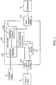
- FIG. 1 is a schematic view of a hub 10 connected with an electronic device 7, an AC power supply 6 and a mobile device 8 according to a first embodiment of the present invention.
- the hub 10 is electrically connected to an electronic device 7, an AC power supply 6 and at least one mobile device 8 that are located outside the hub 10.
- the hub 10 includes a power module 12, a USB Type-C connection terminal 14, a USB connection terminal 15, a power distribution control circuit 13, and a first PD controller 16.
- the power module 12 includes an AC/DC converter 121 and a first DC/DC converter 122.
- the AC/DC converter 121 is electrically connected to the first DC/DC converter 122. Therefore, the power module 12 is a power supply.
- the power module 12 is electrically connected to the AC power supply 6 to receive AC power.
- the AC power is converted into DC power by the AC/DC converter 121, and the AC/DC converter 121 can increase or decrease the voltage of the DC power. Therefore, the converted DC power is suitable for the electronic device 7 with a different voltage.
- the USB connector 15 is electrically connected to the first DC/DC converter 122 of the power module 12 and the mobile device 8. Therefore, after the DC power converted by the AC/DC converter 121 is provided to the first DC/DC converter 122, the first DC/DC converter 122 supplies the DC power to the mobile device 8.
- the mobile device 8 is, for example, an intelligent phone, tablet computer, or notebook computer.
- USB Type-C connection terminal 14 is electrically connected to the AC/DC converter 121 of the power module 12 and the electronic device 7, so that the DC power converted by the AC/DC converter 121 is provided to the electronic device 7.
- the electronic device 7 is, for example, a notebook computer.
- the power distribution control circuit 13 is electrically connected to the power module 12.
- the first PD controller 16 is connected between the USB Type-C connection terminal 14 and the power distribution control circuit 13.
- the power distribution control circuit 13 is used for measuring a measurement value of the power module 12.
- the measurement value is, for example, an electric power value, a voltage value, a current value, or a temperature value.
- the power distribution control circuit 13 will decrease the charging power of the electronic device 7 via the first PD controller 16.
- the power module 12 supplies 7.5 W of electric power to the smart phone, so the power distribution control circuit 13 measures the measurement value of 7.5 W.
- the power module 12 supplies 7.5 W of electric power to the smart phone and 60 W of electric power to the notebook computer, so the measurement value measured by the power distribution control circuit 13 is 67.5W.
- the measurement upper limit value of the hub 10 will be set to 60 W (the measurement value at this time is not less than the measurement upper limit value).
- the power distribution control circuit 13 communicates with the first PD controller 16 and reduces the charging power of the electronic device 7 (for example, from 60 W to 50 W) by changing the charging current, so that the total power of the notebook computer and the smart phone is 57.5W, less than the upper limit value of 60W.
- the power module 12 can preferentially supply stable power to the smart phone.
- the power distribution control circuit 13 will increase the charging power of the electronic device 7 via the first PD controller 16. For example, when the smart phone is gradually charged full, the total power gradually decreases from 57.5 W to 50 W (the lower limit value of the hub 10 is set to 52.5 W).
- the power distribution control circuit 13 communicates with the first PD controller 16 and increases the charging power of the electronic device 7 (from 50 W to 60 W) by changing the charging current until the notebook computer is gradually charged full, and the charging power gradually decreases from 60 W (at this time, even if the charging power is less than 50 W, the measurement upper limit value set by the first PD controller 16 is still 60 W).
- the hub 10 of this embodiment can appropriately distribute the electric power to the notebook computer (electronic device 7) and the smart phone (mobile device 8), so the charging power of the smart phone is not limited (can enter fast charge mode). Therefore, there is no need for the hub 10 to have a high-power power supply, so the manufacturing cost and size of the hub can be reduced.
- the measurement value uses the electric power value as an example.
- other physical quantities can be used as the measurement value, such as temperature.
- the measurement value is a temperature value
- the measurement upper limit value is usually set to a temperature of 75° C, so that the temperature of the hub 10 won't be too high.
- the power distribution control circuit 13 decreases the charging power of the electronic device 7 via the first PD controller 16. In this way, as the total charging power drops, the heat generated by the hub 10 also decreases, and the temperature of the hub 10 also decreases accordingly.
- the measurement value is a voltage value
- the measurement upper limit value is usually set to a voltage value of 20V.
- the measurement upper limit value is usually set to a current value of 3A. The voltage value multiplied by the current value is the electric power value.
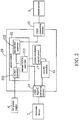
- FIG. 2 is a schematic view of a hub 20 connected with external devices according to a second embodiment of the present invention.
- the power module 22 of the hub 20 further includes a second DC/DC converter 223.
- the AC/DC converter 221 is electrically connected to the first DC/DC converter 122 and the second DC/DC converter 223.
- the AC/DC converter 221 of the hub 20 cannot increase or decrease the voltage of the AC power and can only convert the AC power to DC power.
- the second DC/DC converter 223 is electrically connected to the USB Type-C connection terminal 14.
- the second DC/DC converter 223 is capable of increasing and decreasing the voltage of the DC power, which is advantageous for the electronic device 7 with a different voltage to receive the DC power. In this way, after the DC power converted by the AC/DC converter 121 is provided to the second DC/DC converter 223, the second DC/DC converter 223 adjusts the voltage of the DC power again. After that, the DC power is then provided to the electronic device 7 again.
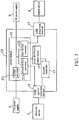
- FIG. 3 is a schematic view of the hub 20 connected with the external devices and a DC power supply 9.
- the hub 20 is further electrically connected to a DC power supply 9.
- the DC power supply 9 may be a car voltage source or a voltage source from a wireless charging receiving circuit.
- the DC power supply 9 is electrically connected to the first DC/DC converter 122 and the second DC/DC converter 223, so the first DC/DC converter 122 and the second DC/DC converter 223 can directly receive the power from the DC power supply 9. In this way, the hub 20 has an additional stable power supply.
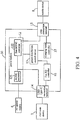
- FIG. 4 is a schematic view of a hub 30 connected with external devices according to a third embodiment of the present invention. The difference between the hub 30 and the hub 10 is described below.
- the hub 30 further includes a charging mode controller 37.
- the charging mode controller 37 is connected between the USB connection terminal 15 and the power distribution control circuit 13.
- the power distribution control circuit 13 will decrease the charging power of the mobile device 8 via the charging mode controller 37.
- the power distribution control circuit 13 communicates with the charging mode controller 37 and decreases the charging power of the mobile device 8 by changing the charging current so that the total power of the electronic device 7 and the mobile device 8 is less than the measurement upper limit value.
- the hub 30 can decrease the charging power of the mobile device 8 via the charging mode controller 37, such that the hub 30 can more appropriately distribute the electric power to the electronic device 7 and the mobile device 8.
- FIG. 5 is a schematic view of a hub 40 connected with external devices according to a fourth embodiment of the present invention.
- the hub 40 further includes a second PD controller 46.
- the second PD controller 46 is connected between the USB connection terminal 15 and the power distribution control circuit 13.
- the power distribution control circuit 13 communicates with the second PD controller 46 and decreases the charging power of the mobile device 8 by changing the charging current, so that the total power of the electric device 7 and the mobile device 8 is less than the measurement upper limit value.
- the hub 40 can decrease the charging power of the mobile device 8 via the second PD controller 46.
- the second PD controller 46 has finer and more flexible control of the charging power (such as controlling the charging voltage level of the mobile device 8, and having a measurement lower limit value detection, or determining whether the electronic device 7 has been charged fully through communication with the first PD controller, thereby improving the charging power of the mobile device 8.).
- the second PD controller 46 may issue instructions to request the mobile device 8 to perform digital signal transmission.
- the electronic device 7 and the mobile device 8 can perform dynamic distribution of the charging mode without exceeding the upper limit value according to different attributes and communication results such as the remaining battery level of each device itself or an acceptable charging mode.
- the hub of the present invention can appropriately distribute the electric power to the electronic device 7 and the mobile device 8, so the charging time of the mobile device 8 is not prolonged.
- the hub of the present invention does not use a high-power power supply. Therefore, the manufacturing cost and the size of the hub can be reduced.
Landscapes
- Engineering & Computer Science (AREA)
- Power Engineering (AREA)
- General Engineering & Computer Science (AREA)
- Theoretical Computer Science (AREA)
- Physics & Mathematics (AREA)
- General Physics & Mathematics (AREA)
- Computer Hardware Design (AREA)
- Automation & Control Theory (AREA)
- Charge And Discharge Circuits For Batteries Or The Like (AREA)
- Power Sources (AREA)
- Direct Current Feeding And Distribution (AREA)
Claims (12)
- Concentrateur (10), adapté pour connecter électriquement un appareil électronique (7), une alimentation électrique CA (6) et au moins un appareil mobile (8) qui sont situés à l'extérieur du concentrateur, le concentrateur (10) caractérisé par le fait qu'il comprend :un module d'alimentation électrique (12), connectable électriquement à l'alimentation électrique CA (6) ;un port de connexion USB (15), connectée électriquement au module d'alimentation électrique (12) et connectable électriquement à l'appareil mobile (8) ;un port de connexion USB de type C (14), connectée électriquement au module d'alimentation électrique (12) et connectable électriquement à l'appareil électronique (7);un circuit de contrôle de la distribution d'alimentation (13), connecté électriquement au module d'alimentation électrique (12), le circuit de contrôle de la distribution d'alimentation (13) étant utilisé pour mesurer une valeur de mesure du module d'alimentation électrique (12) ; etun premier contrôleur de distribution d'alimentation (16), connecté entre le port de connexion USB de type C (14) et le circuit de contrôle de la distribution d'alimentation (13) ;caractérisé en ce que,lorsque la valeur de mesure n'est pas inférieure à une valeur limite supérieure de mesure, le circuit de contrôle de la distribution d'alimentation (13) diminue une puissance de charge de l'appareil électronique (7), lorsque connecté, via le premier contrôleur de distribution d'alimentation (16) ; et ne diminue pas une puissance de charge de l'appareil mobile (8), lorsque connecté, via le premier contrôleur de distribution d'alimentation (16)
- Concentrateur (10) selon la revendication 1, caractérisé par le fait que lorsque la valeur de mesure est inférieure à une valeur limite inférieure de mesure, le circuit de contrôle de la distribution d'alimentation (13) augmente la puissance de charge de l'appareil électronique (7), lorsque connecté via le premier contrôleur de distribution d'alimentation (16).
- Concentrateur (10) selon la revendication 1, caractérisé par le fait que le module d'alimentation électrique (12) comprend un convertisseur CA/CC (121) et un premier convertisseur CC/CC (122), le convertisseur CA/CC (121) est connecté électriquement au premier convertisseur CC/CC (122) et au port de connexion USB de type C (14), et le premier convertisseur CC/CC (122) est connecté électriquement au port de connexion USB (15).
- Concentrateur (20) selon la revendication 1, caractérisé par le fait que le module d'alimentation électrique comprend un convertisseur CA/CC (221), un premier convertisseur CC/CC (122) et un second convertisseur CC/CC (223), le convertisseur CA/CC (221) est connecté électriquement au premier convertisseur CC/CC (122) et au second convertisseur CC/CC (223), le premier convertisseur CC/CC (122) est connecté électriquement au port de connexion USB (15), et le second convertisseur CC/CC (223) est connecté électriquement au port de connexion USB de type C (14).
- Concentrateur (20) selon la revendication 4, caractérisé par le fait que le concentrateur est adapté pour connecter électriquement une alimentation électrique CC (9) située à l'extérieur du concentrateur, et l'alimentation électrique CC est connectable électriquement au premier convertisseur CC/CC (122) et au second convertisseur CC/CC (223).
- Concentrateur selon la revendication 2, caractérisé par le fait que la valeur de mesure est une valeur d'énergie électrique, une valeur de tension, une valeur d'intensité, ou une valeur de température.
- Concentrateur selon la revendication 6, caractérisé par le fait que lorsque la valeur de mesure est la valeur d'énergie électrique, la valeur limite supérieure de mesure est de 60W, et la valeur limite inférieure de mesure est de 52,5W.
- Concentrateur selon la revendication 6, caractérisé par le fait que lorsque la valeur de mesure est la valeur de tension, la valeur limite supérieure de mesure est de 20V.
- Concentrateur selon la revendication 6, caractérisé par le fait que lorsque la valeur de mesure est la valeur d'intensité, la valeur limite supérieure de mesure est de 3A.
- Concentrateur selon la revendication 6, caractérisé par le fait que lorsque la valeur de mesure est la valeur de température, la valeur limite supérieure de mesure est de 75°C.
- Concentrateur selon la revendication 1, caractérisé par le fait qu'il comprend en outre un contrôleur de mode de chargement (37), le contrôleur de mode de chargement (37) étant connecté entre le port de connexion USB (15) et le circuit de contrôle de la distribution d'alimentation ; lorsque la valeur de mesure n'est pas inférieure à la valeur limite supérieure de mesure, le circuit de contrôle de la distribution d'alimentation diminue une puissance de charge de l'appareil mobile (8), lorsque connecté, via le contrôleur de mode de chargement.
- Concentrateur selon la revendication 1, caractérisé par le fait qu'il comprend en outre un second contrôleur de distribution d'alimentation (46), le second contrôleur de distribution d'alimentation étant connecté entre le port de connexion USB (15) et le circuit de contrôle de la distribution d'alimentation ; lorsque la valeur de mesure n'est pas inférieure à la valeur limite supérieure de mesure, le circuit de contrôle de la distribution d'alimentation diminue une puissance de charge de l'appareil mobile via le second contrôleur de distribution d'alimentation.
Applications Claiming Priority (1)
| Application Number | Priority Date | Filing Date | Title |
|---|---|---|---|
| US201762516685P | 2017-06-08 | 2017-06-08 |
Publications (2)
| Publication Number | Publication Date |
|---|---|
| EP3413426A1 EP3413426A1 (fr) | 2018-12-12 |
| EP3413426B1 true EP3413426B1 (fr) | 2020-08-05 |
Family
ID=62567523
Family Applications (1)
| Application Number | Title | Priority Date | Filing Date |
|---|---|---|---|
| EP18176679.1A Active EP3413426B1 (fr) | 2017-06-08 | 2018-06-08 | Concentrateur |
Country Status (5)
| Country | Link |
|---|---|
| US (1) | US10673256B2 (fr) |
| EP (1) | EP3413426B1 (fr) |
| JP (1) | JP2018206394A (fr) |
| CN (1) | CN108777509B (fr) |
| TW (1) | TWI681297B (fr) |
Families Citing this family (18)
| Publication number | Priority date | Publication date | Assignee | Title |
|---|---|---|---|---|
| US11054878B2 (en) * | 2017-08-29 | 2021-07-06 | Texas Instruments Incorporated | Synchronous power state control scheme for multi-chip integrated power management solution in embedded systems |
| US12119701B2 (en) | 2018-09-18 | 2024-10-15 | Leviton Manufacturing Co., Inc. | Systems and methods for universal serial bus (USB) power delivery with multiple charging ports |
| US10923941B2 (en) | 2018-09-18 | 2021-02-16 | Leviton Manufacturing Company, Inc. | Systems and methods for universal serial bus (USB) power delivery with multiple charging ports |
| EP3680996A4 (fr) * | 2018-11-26 | 2020-08-19 | Guangdong Gopod Group Co., Ltd. | Concentrateur ayant une alimentation électrique mobile enfichable |
| US10574070B1 (en) * | 2019-01-19 | 2020-02-25 | Simpower Technology Inc. | Multi-functional hub integrated with AC power supply |
| US11735948B2 (en) * | 2019-07-26 | 2023-08-22 | Baidu Usa Llc | Bi-directional multi-function converter for backup battery unit |
| KR20210021858A (ko) * | 2019-08-19 | 2021-03-02 | 삼성전자주식회사 | 전력 관리를 위한 위한 전자 장치 및 그의 동작 방법 |
| US12283896B2 (en) * | 2019-10-07 | 2025-04-22 | Cooler Master Development Corporation | Computer power supply assembly |
| US11119548B2 (en) * | 2020-01-08 | 2021-09-14 | Cypress Semiconductor Corporation | Dynamic power throttling based on system conditions in USB Type-C power delivery (USB-C/PD) ecosystem |
| US11539306B2 (en) * | 2020-04-03 | 2022-12-27 | Pass & Seymour, Inc. | Electrical wiring device for delivering power to multiple mobile devices |
| WO2022177548A1 (fr) * | 2021-02-16 | 2022-08-25 | Leviton Manufacturing Co., Inc. | Systèmes et procédés de distribution électrique par bus série universel (usb) à plusieurs ports de charge |
| US11599149B2 (en) * | 2021-08-06 | 2023-03-07 | Dell Products, L.P. | Docking station supporting power inputs from a display |
| CN114039389B (zh) | 2021-10-14 | 2024-12-24 | 昂宝电子(上海)有限公司 | 多端口充电设备及其协议握手实现架构和方法 |
| CN114552709A (zh) * | 2022-02-21 | 2022-05-27 | 昂宝电子(上海)有限公司 | 多口usb充电系统及其控制方法 |
| JP7824020B2 (ja) * | 2022-06-27 | 2026-03-04 | アルプスアルパイン株式会社 | 電力分配装置 |
| JP2025050552A (ja) | 2023-09-25 | 2025-04-04 | アルプスアルパイン株式会社 | 給電装置、給電システムおよび制御方法 |
| CN221200265U (zh) * | 2023-11-28 | 2024-06-21 | 安克创新科技股份有限公司 | 一种控制系统和集线器 |
| JP2025110491A (ja) | 2024-01-16 | 2025-07-29 | アルプスアルパイン株式会社 | 給電装置、給電システムおよび制御方法 |
Family Cites Families (22)
| Publication number | Priority date | Publication date | Assignee | Title |
|---|---|---|---|---|
| US6959869B2 (en) * | 1999-06-07 | 2005-11-01 | Metrologic Instruments, Inc. | Automatic vehicle identification (AVI) system employing planar laser illumination and imaging (PLIIM) based subsystems |
| TW534523U (en) | 2001-11-02 | 2003-05-21 | Hau Li Lai Invest Co Ltd | Uninterruptible power device with USB hub |
| US11038298B2 (en) * | 2006-11-09 | 2021-06-15 | The Wiremold Company | Electrical pop out device |
| US10184649B2 (en) * | 2011-06-16 | 2019-01-22 | Tseng-Lu Chien | Quickly charger has USB charging-ports for lighting device |
| TWI498740B (zh) * | 2010-05-05 | 2015-09-01 | Genesys Logic Inc | 通用串列匯流排充電系統及其充電方法 |
| CN102255376A (zh) * | 2010-05-20 | 2011-11-23 | 系统电子工业股份有限公司 | 结合集线器功能的移动式备用电源装置及其使用方法 |
| CN201742147U (zh) * | 2010-05-21 | 2011-02-09 | 系统电子工业股份有限公司 | 具有电源管理功能的移动式备用电源装置 |
| CN102263423B (zh) * | 2010-05-26 | 2013-10-02 | 创惟科技股份有限公司 | 通用串行总线充电系统及其充电方法 |
| DE102011112023B3 (de) * | 2011-08-31 | 2012-10-18 | Sysgration Ltd. | Mobile Ersatzstromversorgung mit einer intergrierten Verteilerfunktion (Hub's function) |
| US20130088188A1 (en) * | 2011-10-11 | 2013-04-11 | Paul Andrew Romanenko | Dedicated USB Power Ports Coupled With A Multi-port USB Powered Hub |
| TWI498704B (zh) | 2012-11-06 | 2015-09-01 | 泰達電子公司 | 可動態調整輸出電壓之電源轉換器及其適用之供電系統 |
| US10277330B2 (en) * | 2013-09-19 | 2019-04-30 | Radius Universal Llc | Fiber optic communications and power network |
| EP3043442B1 (fr) * | 2015-01-12 | 2024-12-04 | SIMPower Technology Inc. | Moyeu doté de convertisseurs de puissance complexes |
| CN104917016B (zh) * | 2015-05-25 | 2017-12-29 | 深圳市华宝新能源股份有限公司 | 充电式集线器 |
| KR20160140275A (ko) * | 2015-05-29 | 2016-12-07 | 삼성전자주식회사 | 동적 전원 제어를 위한 전자 장치 및 그 방법 |
| US10224727B2 (en) * | 2015-06-30 | 2019-03-05 | Dong-Sheng Li | Multi-functional hub integrated with AC power supply |
| JP6623306B2 (ja) * | 2015-11-16 | 2019-12-18 | モレックス エルエルシー | 電力充電モジュール及びその使用方法 |
| US10545907B2 (en) * | 2015-12-24 | 2020-01-28 | Intel Corporation | Adjustable power delivery scheme for universal serial bus |
| WO2017111859A1 (fr) * | 2015-12-24 | 2017-06-29 | Intel Corporation | Système électronique à adaptateur d'alimentation pour charge filaire et sans fil |
| CN105608035B (zh) * | 2015-12-25 | 2018-12-04 | 深圳罗马仕科技有限公司 | Type-C型USB集线器 |
| US20170293335A1 (en) * | 2016-04-08 | 2017-10-12 | Robert A. Dunstan | Adjustable power delivery apparatus for universal serial bus (usb) type-c |
| US10199940B1 (en) * | 2017-03-28 | 2019-02-05 | ENRG-dc, Inc. | Direct current power delivery system |
-
2018
- 2018-06-05 JP JP2018108176A patent/JP2018206394A/ja active Pending
- 2018-06-08 TW TW107119937A patent/TWI681297B/zh active
- 2018-06-08 CN CN201810588934.XA patent/CN108777509B/zh active Active
- 2018-06-08 EP EP18176679.1A patent/EP3413426B1/fr active Active
- 2018-06-08 US US16/003,217 patent/US10673256B2/en active Active
Non-Patent Citations (1)
| Title |
|---|
| None * |
Also Published As
| Publication number | Publication date |
|---|---|
| US10673256B2 (en) | 2020-06-02 |
| CN108777509B (zh) | 2021-05-11 |
| CN108777509A (zh) | 2018-11-09 |
| TW201903618A (zh) | 2019-01-16 |
| US20180358821A1 (en) | 2018-12-13 |
| EP3413426A1 (fr) | 2018-12-12 |
| JP2018206394A (ja) | 2018-12-27 |
| TWI681297B (zh) | 2020-01-01 |
Similar Documents
| Publication | Publication Date | Title |
|---|---|---|
| EP3413426B1 (fr) | Concentrateur | |
| US11575280B2 (en) | Electronic device and method for wire and wireless charging in electronic device | |
| KR101870769B1 (ko) | 복합 전원변환기를 갖는 허브 | |
| US11290801B2 (en) | Headset charging system and headset charging method | |
| CN104272550B (zh) | 受电控制电路、无线受电装置的控制方法、电子设备 | |
| US9153999B2 (en) | Circuits and methods for automatic power source detection | |
| JP6626384B2 (ja) | 給電装置および給電方法、制御回路、acアダプタ、電子機器 | |
| US20180262115A1 (en) | Bus controller | |
| US9997943B2 (en) | Electronic device and power adapter capable of communicating with each other, and associated charging system | |
| KR20200101228A (ko) | 외부 장치를 무선 충전하기 위한 전자 장치 | |
| US20170229892A1 (en) | Power receiving device, controller thereof, electronic apparatus including the same, and control method of power feed system | |
| US11837887B2 (en) | Charging integrated circuit and operating method | |
| US10491039B2 (en) | Power transfer circuit and method utilizing power capability proclamation to transfer electrical power to charger | |
| KR20210109916A (ko) | 무선 충전 장치 및 방법 | |
| US10333380B2 (en) | Electronic device | |
| US10686324B2 (en) | Electronic apparatus and charging method thereof | |
| KR20210119661A (ko) | 무선 충전 장치 및 방법 | |
| KR20200113864A (ko) | 무선 전력 수신 장치 및 그 제어 방법 | |
| KR102838545B1 (ko) | 무선 충전 중에 이물질을 검출하는 무선 충전 방법 및 시스템 | |
| KR20200042376A (ko) | 전자 장치 및 전자 장치에서 유무선 충전 방법 | |
| KR20210128607A (ko) | 전자 장치 및 상기 전자 장치의 충전 상태 정보를 제공하는 방법 | |
| JP2020198671A (ja) | 受電装置およびその制御回路、給電装置と受電装置のネゴシエーションの方法 | |
| US20170070064A1 (en) | Electronic device, method for controlling electronic device and program for controlling electronic device | |
| KR20250178173A (ko) | 배터리의 탈부착이 가능한 전자 장치 및 그의 구동 방법 |
Legal Events
| Date | Code | Title | Description |
|---|---|---|---|
| PUAI | Public reference made under article 153(3) epc to a published international application that has entered the european phase |
Free format text: ORIGINAL CODE: 0009012 |
|
| STAA | Information on the status of an ep patent application or granted ep patent |
Free format text: STATUS: THE APPLICATION HAS BEEN PUBLISHED |
|
| AK | Designated contracting states |
Kind code of ref document: A1 Designated state(s): AL AT BE BG CH CY CZ DE DK EE ES FI FR GB GR HR HU IE IS IT LI LT LU LV MC MK MT NL NO PL PT RO RS SE SI SK SM TR |
|
| AX | Request for extension of the european patent |
Extension state: BA ME |
|
| STAA | Information on the status of an ep patent application or granted ep patent |
Free format text: STATUS: REQUEST FOR EXAMINATION WAS MADE |
|
| 17P | Request for examination filed |
Effective date: 20190611 |
|
| RBV | Designated contracting states (corrected) |
Designated state(s): AL AT BE BG CH CY CZ DE DK EE ES FI FR GB GR HR HU IE IS IT LI LT LU LV MC MK MT NL NO PL PT RO RS SE SI SK SM TR |
|
| GRAP | Despatch of communication of intention to grant a patent |
Free format text: ORIGINAL CODE: EPIDOSNIGR1 |
|
| STAA | Information on the status of an ep patent application or granted ep patent |
Free format text: STATUS: GRANT OF PATENT IS INTENDED |
|
| INTG | Intention to grant announced |
Effective date: 20200403 |
|
| RAP1 | Party data changed (applicant data changed or rights of an application transferred) |
Owner name: SIMPOWER TECHNOLOGY INC. |
|
| GRAS | Grant fee paid |
Free format text: ORIGINAL CODE: EPIDOSNIGR3 |
|
| GRAA | (expected) grant |
Free format text: ORIGINAL CODE: 0009210 |
|
| STAA | Information on the status of an ep patent application or granted ep patent |
Free format text: STATUS: THE PATENT HAS BEEN GRANTED |
|
| AK | Designated contracting states |
Kind code of ref document: B1 Designated state(s): AL AT BE BG CH CY CZ DE DK EE ES FI FR GB GR HR HU IE IS IT LI LT LU LV MC MK MT NL NO PL PT RO RS SE SI SK SM TR |
|
| REG | Reference to a national code |
Ref country code: GB Ref legal event code: FG4D |
|
| REG | Reference to a national code |
Ref country code: CH Ref legal event code: EP |
|
| REG | Reference to a national code |
Ref country code: AT Ref legal event code: REF Ref document number: 1300080 Country of ref document: AT Kind code of ref document: T Effective date: 20200815 |
|
| REG | Reference to a national code |
Ref country code: DE Ref legal event code: R096 Ref document number: 602018006577 Country of ref document: DE |
|
| REG | Reference to a national code |
Ref country code: IE Ref legal event code: FG4D |
|
| REG | Reference to a national code |
Ref country code: LT Ref legal event code: MG4D |
|
| REG | Reference to a national code |
Ref country code: NL Ref legal event code: MP Effective date: 20200805 |
|
| REG | Reference to a national code |
Ref country code: AT Ref legal event code: MK05 Ref document number: 1300080 Country of ref document: AT Kind code of ref document: T Effective date: 20200805 |
|
| PG25 | Lapsed in a contracting state [announced via postgrant information from national office to epo] |
Ref country code: FI Free format text: LAPSE BECAUSE OF FAILURE TO SUBMIT A TRANSLATION OF THE DESCRIPTION OR TO PAY THE FEE WITHIN THE PRESCRIBED TIME-LIMIT Effective date: 20200805 Ref country code: HR Free format text: LAPSE BECAUSE OF FAILURE TO SUBMIT A TRANSLATION OF THE DESCRIPTION OR TO PAY THE FEE WITHIN THE PRESCRIBED TIME-LIMIT Effective date: 20200805 Ref country code: AT Free format text: LAPSE BECAUSE OF FAILURE TO SUBMIT A TRANSLATION OF THE DESCRIPTION OR TO PAY THE FEE WITHIN THE PRESCRIBED TIME-LIMIT Effective date: 20200805 Ref country code: LT Free format text: LAPSE BECAUSE OF FAILURE TO SUBMIT A TRANSLATION OF THE DESCRIPTION OR TO PAY THE FEE WITHIN THE PRESCRIBED TIME-LIMIT Effective date: 20200805 Ref country code: BG Free format text: LAPSE BECAUSE OF FAILURE TO SUBMIT A TRANSLATION OF THE DESCRIPTION OR TO PAY THE FEE WITHIN THE PRESCRIBED TIME-LIMIT Effective date: 20201105 Ref country code: PT Free format text: LAPSE BECAUSE OF FAILURE TO SUBMIT A TRANSLATION OF THE DESCRIPTION OR TO PAY THE FEE WITHIN THE PRESCRIBED TIME-LIMIT Effective date: 20201207 Ref country code: ES Free format text: LAPSE BECAUSE OF FAILURE TO SUBMIT A TRANSLATION OF THE DESCRIPTION OR TO PAY THE FEE WITHIN THE PRESCRIBED TIME-LIMIT Effective date: 20200805 Ref country code: NO Free format text: LAPSE BECAUSE OF FAILURE TO SUBMIT A TRANSLATION OF THE DESCRIPTION OR TO PAY THE FEE WITHIN THE PRESCRIBED TIME-LIMIT Effective date: 20201105 Ref country code: GR Free format text: LAPSE BECAUSE OF FAILURE TO SUBMIT A TRANSLATION OF THE DESCRIPTION OR TO PAY THE FEE WITHIN THE PRESCRIBED TIME-LIMIT Effective date: 20201106 Ref country code: SE Free format text: LAPSE BECAUSE OF FAILURE TO SUBMIT A TRANSLATION OF THE DESCRIPTION OR TO PAY THE FEE WITHIN THE PRESCRIBED TIME-LIMIT Effective date: 20200805 |
|
| PG25 | Lapsed in a contracting state [announced via postgrant information from national office to epo] |
Ref country code: PL Free format text: LAPSE BECAUSE OF FAILURE TO SUBMIT A TRANSLATION OF THE DESCRIPTION OR TO PAY THE FEE WITHIN THE PRESCRIBED TIME-LIMIT Effective date: 20200805 Ref country code: LV Free format text: LAPSE BECAUSE OF FAILURE TO SUBMIT A TRANSLATION OF THE DESCRIPTION OR TO PAY THE FEE WITHIN THE PRESCRIBED TIME-LIMIT Effective date: 20200805 Ref country code: RS Free format text: LAPSE BECAUSE OF FAILURE TO SUBMIT A TRANSLATION OF THE DESCRIPTION OR TO PAY THE FEE WITHIN THE PRESCRIBED TIME-LIMIT Effective date: 20200805 Ref country code: NL Free format text: LAPSE BECAUSE OF FAILURE TO SUBMIT A TRANSLATION OF THE DESCRIPTION OR TO PAY THE FEE WITHIN THE PRESCRIBED TIME-LIMIT Effective date: 20200805 Ref country code: IS Free format text: LAPSE BECAUSE OF FAILURE TO SUBMIT A TRANSLATION OF THE DESCRIPTION OR TO PAY THE FEE WITHIN THE PRESCRIBED TIME-LIMIT Effective date: 20201205 |
|
| PG25 | Lapsed in a contracting state [announced via postgrant information from national office to epo] |
Ref country code: SM Free format text: LAPSE BECAUSE OF FAILURE TO SUBMIT A TRANSLATION OF THE DESCRIPTION OR TO PAY THE FEE WITHIN THE PRESCRIBED TIME-LIMIT Effective date: 20200805 Ref country code: EE Free format text: LAPSE BECAUSE OF FAILURE TO SUBMIT A TRANSLATION OF THE DESCRIPTION OR TO PAY THE FEE WITHIN THE PRESCRIBED TIME-LIMIT Effective date: 20200805 Ref country code: RO Free format text: LAPSE BECAUSE OF FAILURE TO SUBMIT A TRANSLATION OF THE DESCRIPTION OR TO PAY THE FEE WITHIN THE PRESCRIBED TIME-LIMIT Effective date: 20200805 Ref country code: CZ Free format text: LAPSE BECAUSE OF FAILURE TO SUBMIT A TRANSLATION OF THE DESCRIPTION OR TO PAY THE FEE WITHIN THE PRESCRIBED TIME-LIMIT Effective date: 20200805 Ref country code: DK Free format text: LAPSE BECAUSE OF FAILURE TO SUBMIT A TRANSLATION OF THE DESCRIPTION OR TO PAY THE FEE WITHIN THE PRESCRIBED TIME-LIMIT Effective date: 20200805 |
|
| REG | Reference to a national code |
Ref country code: DE Ref legal event code: R097 Ref document number: 602018006577 Country of ref document: DE |
|
| PG25 | Lapsed in a contracting state [announced via postgrant information from national office to epo] |
Ref country code: AL Free format text: LAPSE BECAUSE OF FAILURE TO SUBMIT A TRANSLATION OF THE DESCRIPTION OR TO PAY THE FEE WITHIN THE PRESCRIBED TIME-LIMIT Effective date: 20200805 |
|
| PLBE | No opposition filed within time limit |
Free format text: ORIGINAL CODE: 0009261 |
|
| STAA | Information on the status of an ep patent application or granted ep patent |
Free format text: STATUS: NO OPPOSITION FILED WITHIN TIME LIMIT |
|
| PG25 | Lapsed in a contracting state [announced via postgrant information from national office to epo] |
Ref country code: SK Free format text: LAPSE BECAUSE OF FAILURE TO SUBMIT A TRANSLATION OF THE DESCRIPTION OR TO PAY THE FEE WITHIN THE PRESCRIBED TIME-LIMIT Effective date: 20200805 |
|
| 26N | No opposition filed |
Effective date: 20210507 |
|
| PG25 | Lapsed in a contracting state [announced via postgrant information from national office to epo] |
Ref country code: IT Free format text: LAPSE BECAUSE OF FAILURE TO SUBMIT A TRANSLATION OF THE DESCRIPTION OR TO PAY THE FEE WITHIN THE PRESCRIBED TIME-LIMIT Effective date: 20200805 |
|
| PG25 | Lapsed in a contracting state [announced via postgrant information from national office to epo] |
Ref country code: SI Free format text: LAPSE BECAUSE OF FAILURE TO SUBMIT A TRANSLATION OF THE DESCRIPTION OR TO PAY THE FEE WITHIN THE PRESCRIBED TIME-LIMIT Effective date: 20200805 |
|
| PG25 | Lapsed in a contracting state [announced via postgrant information from national office to epo] |
Ref country code: MC Free format text: LAPSE BECAUSE OF FAILURE TO SUBMIT A TRANSLATION OF THE DESCRIPTION OR TO PAY THE FEE WITHIN THE PRESCRIBED TIME-LIMIT Effective date: 20200805 |
|
| REG | Reference to a national code |
Ref country code: CH Ref legal event code: PL |
|
| REG | Reference to a national code |
Ref country code: BE Ref legal event code: MM Effective date: 20210630 |
|
| PG25 | Lapsed in a contracting state [announced via postgrant information from national office to epo] |
Ref country code: LU Free format text: LAPSE BECAUSE OF NON-PAYMENT OF DUE FEES Effective date: 20210608 |
|
| PG25 | Lapsed in a contracting state [announced via postgrant information from national office to epo] |
Ref country code: LI Free format text: LAPSE BECAUSE OF NON-PAYMENT OF DUE FEES Effective date: 20210630 Ref country code: IE Free format text: LAPSE BECAUSE OF NON-PAYMENT OF DUE FEES Effective date: 20210608 Ref country code: CH Free format text: LAPSE BECAUSE OF NON-PAYMENT OF DUE FEES Effective date: 20210630 |
|
| PG25 | Lapsed in a contracting state [announced via postgrant information from national office to epo] |
Ref country code: BE Free format text: LAPSE BECAUSE OF NON-PAYMENT OF DUE FEES Effective date: 20210630 |
|
| PG25 | Lapsed in a contracting state [announced via postgrant information from national office to epo] |
Ref country code: CY Free format text: LAPSE BECAUSE OF FAILURE TO SUBMIT A TRANSLATION OF THE DESCRIPTION OR TO PAY THE FEE WITHIN THE PRESCRIBED TIME-LIMIT Effective date: 20200805 |
|
| PG25 | Lapsed in a contracting state [announced via postgrant information from national office to epo] |
Ref country code: HU Free format text: LAPSE BECAUSE OF FAILURE TO SUBMIT A TRANSLATION OF THE DESCRIPTION OR TO PAY THE FEE WITHIN THE PRESCRIBED TIME-LIMIT; INVALID AB INITIO Effective date: 20180608 |
|
| PG25 | Lapsed in a contracting state [announced via postgrant information from national office to epo] |
Ref country code: MK Free format text: LAPSE BECAUSE OF FAILURE TO SUBMIT A TRANSLATION OF THE DESCRIPTION OR TO PAY THE FEE WITHIN THE PRESCRIBED TIME-LIMIT Effective date: 20200805 |
|
| PG25 | Lapsed in a contracting state [announced via postgrant information from national office to epo] |
Ref country code: TR Free format text: LAPSE BECAUSE OF FAILURE TO SUBMIT A TRANSLATION OF THE DESCRIPTION OR TO PAY THE FEE WITHIN THE PRESCRIBED TIME-LIMIT Effective date: 20200805 |
|
| REG | Reference to a national code |
Ref country code: DE Ref legal event code: R082 Ref document number: 602018006577 Country of ref document: DE Representative=s name: STRAUS, ALEXANDER, DIPL.-CHEM.UNIV. DR.PHIL., DE |
|
| PG25 | Lapsed in a contracting state [announced via postgrant information from national office to epo] |
Ref country code: MT Free format text: LAPSE BECAUSE OF FAILURE TO SUBMIT A TRANSLATION OF THE DESCRIPTION OR TO PAY THE FEE WITHIN THE PRESCRIBED TIME-LIMIT Effective date: 20200805 |
|
| PGFP | Annual fee paid to national office [announced via postgrant information from national office to epo] |
Ref country code: FR Payment date: 20250626 Year of fee payment: 8 |
|
| REG | Reference to a national code |
Ref country code: DE Ref legal event code: R081 Ref document number: 602018006577 Country of ref document: DE Owner name: PATENTBRIDGE SOLUTIONS LLC, AUSTIN, US Free format text: FORMER OWNER: SIMPOWER TECHNOLOGY INC., TAIPEI CITY, TW |
|
| REG | Reference to a national code |
Ref country code: GB Ref legal event code: 732E Free format text: REGISTERED BETWEEN 20250911 AND 20250917 |
|
| PGFP | Annual fee paid to national office [announced via postgrant information from national office to epo] |
Ref country code: DE Payment date: 20250627 Year of fee payment: 8 |
|
| PGFP | Annual fee paid to national office [announced via postgrant information from national office to epo] |
Ref country code: GB Payment date: 20250724 Year of fee payment: 8 |