EP3414053B1 - Schleifscheibe - Google Patents
Schleifscheibe Download PDFInfo
- Publication number
- EP3414053B1 EP3414053B1 EP17706936.6A EP17706936A EP3414053B1 EP 3414053 B1 EP3414053 B1 EP 3414053B1 EP 17706936 A EP17706936 A EP 17706936A EP 3414053 B1 EP3414053 B1 EP 3414053B1
- Authority
- EP
- European Patent Office
- Prior art keywords
- microns
- glass substrate
- volume
- abrasive
- particle size
- Prior art date
- Legal status (The legal status is an assumption and is not a legal conclusion. Google has not performed a legal analysis and makes no representation as to the accuracy of the status listed.)
- Active
Links
- 238000000227 grinding Methods 0.000 title claims description 58
- 239000002245 particle Substances 0.000 claims description 178
- 239000010432 diamond Substances 0.000 claims description 58
- 229910003460 diamond Inorganic materials 0.000 claims description 55
- 239000011159 matrix material Substances 0.000 claims description 41
- 229910052751 metal Inorganic materials 0.000 claims description 30
- 239000002184 metal Substances 0.000 claims description 30
- 229920005989 resin Polymers 0.000 claims description 17
- 239000011347 resin Substances 0.000 claims description 17
- 239000011163 secondary particle Substances 0.000 claims description 17
- XEEYBQQBJWHFJM-UHFFFAOYSA-N Iron Chemical compound [Fe] XEEYBQQBJWHFJM-UHFFFAOYSA-N 0.000 claims description 16
- 239000011164 primary particle Substances 0.000 claims description 13
- 229910052742 iron Inorganic materials 0.000 claims description 10
- 239000000758 substrate Substances 0.000 description 208
- 239000011521 glass Substances 0.000 description 172
- 239000000203 mixture Substances 0.000 description 37
- 239000011229 interlayer Substances 0.000 description 34
- VYPSYNLAJGMNEJ-UHFFFAOYSA-N silicon dioxide Inorganic materials O=[Si]=O VYPSYNLAJGMNEJ-UHFFFAOYSA-N 0.000 description 24
- 239000000463 material Substances 0.000 description 21
- 238000000034 method Methods 0.000 description 21
- PNEYBMLMFCGWSK-UHFFFAOYSA-N aluminium oxide Inorganic materials [O-2].[O-2].[O-2].[Al+3].[Al+3] PNEYBMLMFCGWSK-UHFFFAOYSA-N 0.000 description 16
- 150000002500 ions Chemical class 0.000 description 15
- KKCBUQHMOMHUOY-UHFFFAOYSA-N Na2O Inorganic materials [O-2].[Na+].[Na+] KKCBUQHMOMHUOY-UHFFFAOYSA-N 0.000 description 13
- 229910052593 corundum Inorganic materials 0.000 description 13
- 239000006058 strengthened glass Substances 0.000 description 13
- 229910001845 yogo sapphire Inorganic materials 0.000 description 13
- 229910011255 B2O3 Inorganic materials 0.000 description 12
- 229910052681 coesite Inorganic materials 0.000 description 12
- 229910052906 cristobalite Inorganic materials 0.000 description 12
- 230000008569 process Effects 0.000 description 12
- 239000000377 silicon dioxide Substances 0.000 description 12
- 229910052682 stishovite Inorganic materials 0.000 description 12
- 238000012360 testing method Methods 0.000 description 12
- 229910052905 tridymite Inorganic materials 0.000 description 12
- FGIUAXJPYTZDNR-UHFFFAOYSA-N potassium nitrate Chemical compound [K+].[O-][N+]([O-])=O FGIUAXJPYTZDNR-UHFFFAOYSA-N 0.000 description 10
- VWDWKYIASSYTQR-UHFFFAOYSA-N sodium nitrate Chemical compound [Na+].[O-][N+]([O-])=O VWDWKYIASSYTQR-UHFFFAOYSA-N 0.000 description 10
- 229920002037 poly(vinyl butyral) polymer Polymers 0.000 description 9
- 150000003839 salts Chemical class 0.000 description 9
- MCMNRKCIXSYSNV-UHFFFAOYSA-N Zirconium dioxide Chemical compound O=[Zr]=O MCMNRKCIXSYSNV-UHFFFAOYSA-N 0.000 description 8
- 238000007654 immersion Methods 0.000 description 8
- 238000005342 ion exchange Methods 0.000 description 7
- 239000005340 laminated glass Substances 0.000 description 7
- 239000005358 alkali aluminosilicate glass Substances 0.000 description 6
- 239000013078 crystal Substances 0.000 description 6
- XOLBLPGZBRYERU-UHFFFAOYSA-N tin dioxide Chemical compound O=[Sn]=O XOLBLPGZBRYERU-UHFFFAOYSA-N 0.000 description 6
- 239000005345 chemically strengthened glass Substances 0.000 description 5
- 238000000576 coating method Methods 0.000 description 5
- 239000010410 layer Substances 0.000 description 5
- 238000004519 manufacturing process Methods 0.000 description 5
- 238000005498 polishing Methods 0.000 description 5
- -1 polyethylene terephthalate Polymers 0.000 description 5
- 229920000642 polymer Polymers 0.000 description 5
- 239000000843 powder Substances 0.000 description 5
- GOLCXWYRSKYTSP-UHFFFAOYSA-N Arsenious Acid Chemical compound O1[As]2O[As]1O2 GOLCXWYRSKYTSP-UHFFFAOYSA-N 0.000 description 4
- FUJCRWPEOMXPAD-UHFFFAOYSA-N Li2O Inorganic materials [Li+].[Li+].[O-2] FUJCRWPEOMXPAD-UHFFFAOYSA-N 0.000 description 4
- 239000003082 abrasive agent Substances 0.000 description 4
- 230000008859 change Effects 0.000 description 4
- XUCJHNOBJLKZNU-UHFFFAOYSA-M dilithium;hydroxide Chemical compound [Li+].[Li+].[OH-] XUCJHNOBJLKZNU-UHFFFAOYSA-M 0.000 description 4
- 239000002241 glass-ceramic Substances 0.000 description 4
- 230000001965 increasing effect Effects 0.000 description 4
- 238000005259 measurement Methods 0.000 description 4
- 229910001414 potassium ion Inorganic materials 0.000 description 4
- HBMJWWWQQXIZIP-UHFFFAOYSA-N silicon carbide Chemical compound [Si+]#[C-] HBMJWWWQQXIZIP-UHFFFAOYSA-N 0.000 description 4
- 229910001415 sodium ion Inorganic materials 0.000 description 4
- 229910000906 Bronze Inorganic materials 0.000 description 3
- 239000003513 alkali Substances 0.000 description 3
- 229910052783 alkali metal Inorganic materials 0.000 description 3
- 238000005452 bending Methods 0.000 description 3
- 239000010974 bronze Substances 0.000 description 3
- 150000001768 cations Chemical class 0.000 description 3
- 230000000052 comparative effect Effects 0.000 description 3
- 230000001747 exhibiting effect Effects 0.000 description 3
- 238000007730 finishing process Methods 0.000 description 3
- 238000010438 heat treatment Methods 0.000 description 3
- 230000006872 improvement Effects 0.000 description 3
- 238000003475 lamination Methods 0.000 description 3
- 230000003137 locomotive effect Effects 0.000 description 3
- 238000002156 mixing Methods 0.000 description 3
- 239000003607 modifier Substances 0.000 description 3
- 238000005096 rolling process Methods 0.000 description 3
- 229910010271 silicon carbide Inorganic materials 0.000 description 3
- 238000005728 strengthening Methods 0.000 description 3
- WCUXLLCKKVVCTQ-UHFFFAOYSA-M Potassium chloride Chemical compound [Cl-].[K+] WCUXLLCKKVVCTQ-UHFFFAOYSA-M 0.000 description 2
- FAPWRFPIFSIZLT-UHFFFAOYSA-M Sodium chloride Chemical compound [Na+].[Cl-] FAPWRFPIFSIZLT-UHFFFAOYSA-M 0.000 description 2
- 239000004433 Thermoplastic polyurethane Substances 0.000 description 2
- 239000006061 abrasive grain Substances 0.000 description 2
- 238000010521 absorption reaction Methods 0.000 description 2
- 229910000287 alkaline earth metal oxide Inorganic materials 0.000 description 2
- 239000005407 aluminoborosilicate glass Substances 0.000 description 2
- 238000004458 analytical method Methods 0.000 description 2
- ADCOVFLJGNWWNZ-UHFFFAOYSA-N antimony trioxide Inorganic materials O=[Sb]O[Sb]=O ADCOVFLJGNWWNZ-UHFFFAOYSA-N 0.000 description 2
- 230000008901 benefit Effects 0.000 description 2
- 230000015572 biosynthetic process Effects 0.000 description 2
- 239000002775 capsule Substances 0.000 description 2
- 239000000919 ceramic Substances 0.000 description 2
- CETPSERCERDGAM-UHFFFAOYSA-N ceric oxide Chemical compound O=[Ce]=O CETPSERCERDGAM-UHFFFAOYSA-N 0.000 description 2
- 229910000422 cerium(IV) oxide Inorganic materials 0.000 description 2
- 150000001875 compounds Chemical class 0.000 description 2
- 239000002826 coolant Substances 0.000 description 2
- 230000006378 damage Effects 0.000 description 2
- 238000013400 design of experiment Methods 0.000 description 2
- 238000009826 distribution Methods 0.000 description 2
- 230000002708 enhancing effect Effects 0.000 description 2
- 230000003628 erosive effect Effects 0.000 description 2
- 238000002474 experimental method Methods 0.000 description 2
- 239000012530 fluid Substances 0.000 description 2
- IIPYXGDZVMZOAP-UHFFFAOYSA-N lithium nitrate Chemical compound [Li+].[O-][N+]([O-])=O IIPYXGDZVMZOAP-UHFFFAOYSA-N 0.000 description 2
- 150000002823 nitrates Chemical class 0.000 description 2
- 229920000728 polyester Polymers 0.000 description 2
- 229920000139 polyethylene terephthalate Polymers 0.000 description 2
- 239000005020 polyethylene terephthalate Substances 0.000 description 2
- 238000012545 processing Methods 0.000 description 2
- 230000004044 response Effects 0.000 description 2
- 230000000717 retained effect Effects 0.000 description 2
- JHJLBTNAGRQEKS-UHFFFAOYSA-M sodium bromide Chemical compound [Na+].[Br-] JHJLBTNAGRQEKS-UHFFFAOYSA-M 0.000 description 2
- PUZPDOWCWNUUKD-UHFFFAOYSA-M sodium fluoride Chemical compound [F-].[Na+] PUZPDOWCWNUUKD-UHFFFAOYSA-M 0.000 description 2
- 239000010935 stainless steel Substances 0.000 description 2
- 229910001220 stainless steel Inorganic materials 0.000 description 2
- 239000002344 surface layer Substances 0.000 description 2
- YEAUATLBSVJFOY-UHFFFAOYSA-N tetraantimony hexaoxide Chemical compound O1[Sb](O2)O[Sb]3O[Sb]1O[Sb]2O3 YEAUATLBSVJFOY-UHFFFAOYSA-N 0.000 description 2
- 229920002803 thermoplastic polyurethane Polymers 0.000 description 2
- XLYOFNOQVPJJNP-UHFFFAOYSA-N water Substances O XLYOFNOQVPJJNP-UHFFFAOYSA-N 0.000 description 2
- 229910052582 BN Inorganic materials 0.000 description 1
- ZOXJGFHDIHLPTG-UHFFFAOYSA-N Boron Chemical compound [B] ZOXJGFHDIHLPTG-UHFFFAOYSA-N 0.000 description 1
- PZNSFCLAULLKQX-UHFFFAOYSA-N Boron nitride Chemical compound N#B PZNSFCLAULLKQX-UHFFFAOYSA-N 0.000 description 1
- DGAQECJNVWCQMB-PUAWFVPOSA-M Ilexoside XXIX Chemical compound C[C@@H]1CC[C@@]2(CC[C@@]3(C(=CC[C@H]4[C@]3(CC[C@@H]5[C@@]4(CC[C@@H](C5(C)C)OS(=O)(=O)[O-])C)C)[C@@H]2[C@]1(C)O)C)C(=O)O[C@H]6[C@@H]([C@H]([C@@H]([C@H](O6)CO)O)O)O.[Na+] DGAQECJNVWCQMB-PUAWFVPOSA-M 0.000 description 1
- 239000006125 LAS system Substances 0.000 description 1
- 229910008556 Li2O—Al2O3—SiO2 Inorganic materials 0.000 description 1
- WHXSMMKQMYFTQS-UHFFFAOYSA-N Lithium Chemical compound [Li] WHXSMMKQMYFTQS-UHFFFAOYSA-N 0.000 description 1
- 239000006126 MAS system Substances 0.000 description 1
- 239000007832 Na2SO4 Substances 0.000 description 1
- BPQQTUXANYXVAA-UHFFFAOYSA-N Orthosilicate Chemical compound [O-][Si]([O-])([O-])[O-] BPQQTUXANYXVAA-UHFFFAOYSA-N 0.000 description 1
- ZLMJMSJWJFRBEC-UHFFFAOYSA-N Potassium Chemical compound [K] ZLMJMSJWJFRBEC-UHFFFAOYSA-N 0.000 description 1
- CDBYLPFSWZWCQE-UHFFFAOYSA-L Sodium Carbonate Chemical compound [Na+].[Na+].[O-]C([O-])=O CDBYLPFSWZWCQE-UHFFFAOYSA-L 0.000 description 1
- PMZURENOXWZQFD-UHFFFAOYSA-L Sodium Sulfate Chemical compound [Na+].[Na+].[O-]S([O-])(=O)=O PMZURENOXWZQFD-UHFFFAOYSA-L 0.000 description 1
- 229910000831 Steel Inorganic materials 0.000 description 1
- 208000027418 Wounds and injury Diseases 0.000 description 1
- 238000005299 abrasion Methods 0.000 description 1
- 239000000654 additive Substances 0.000 description 1
- 230000000996 additive effect Effects 0.000 description 1
- 229910001413 alkali metal ion Inorganic materials 0.000 description 1
- 229910000272 alkali metal oxide Inorganic materials 0.000 description 1
- 150000001340 alkali metals Chemical class 0.000 description 1
- HEHRHMRHPUNLIR-UHFFFAOYSA-N aluminum;hydroxy-[hydroxy(oxo)silyl]oxy-oxosilane;lithium Chemical compound [Li].[Al].O[Si](=O)O[Si](O)=O.O[Si](=O)O[Si](O)=O HEHRHMRHPUNLIR-UHFFFAOYSA-N 0.000 description 1
- CNLWCVNCHLKFHK-UHFFFAOYSA-N aluminum;lithium;dioxido(oxo)silane Chemical compound [Li+].[Al+3].[O-][Si]([O-])=O.[O-][Si]([O-])=O CNLWCVNCHLKFHK-UHFFFAOYSA-N 0.000 description 1
- 238000000137 annealing Methods 0.000 description 1
- 230000033228 biological regulation Effects 0.000 description 1
- 229910052796 boron Inorganic materials 0.000 description 1
- 239000005388 borosilicate glass Substances 0.000 description 1
- 239000003054 catalyst Substances 0.000 description 1
- 238000001311 chemical methods and process Methods 0.000 description 1
- 150000003841 chloride salts Chemical class 0.000 description 1
- 239000011248 coating agent Substances 0.000 description 1
- 238000004891 communication Methods 0.000 description 1
- 230000006835 compression Effects 0.000 description 1
- 238000007906 compression Methods 0.000 description 1
- KUNSUQLRTQLHQQ-UHFFFAOYSA-N copper tin Chemical compound [Cu].[Sn] KUNSUQLRTQLHQQ-UHFFFAOYSA-N 0.000 description 1
- 238000005520 cutting process Methods 0.000 description 1
- 238000013016 damping Methods 0.000 description 1
- 230000007423 decrease Effects 0.000 description 1
- 230000007547 defect Effects 0.000 description 1
- 238000009792 diffusion process Methods 0.000 description 1
- WVMPCBWWBLZKPD-UHFFFAOYSA-N dilithium oxido-[oxido(oxo)silyl]oxy-oxosilane Chemical compound [Li+].[Li+].[O-][Si](=O)O[Si]([O-])=O WVMPCBWWBLZKPD-UHFFFAOYSA-N 0.000 description 1
- KZHJGOXRZJKJNY-UHFFFAOYSA-N dioxosilane;oxo(oxoalumanyloxy)alumane Chemical compound O=[Si]=O.O=[Si]=O.O=[Al]O[Al]=O.O=[Al]O[Al]=O.O=[Al]O[Al]=O KZHJGOXRZJKJNY-UHFFFAOYSA-N 0.000 description 1
- 239000002019 doping agent Substances 0.000 description 1
- 238000009837 dry grinding Methods 0.000 description 1
- 230000000694 effects Effects 0.000 description 1
- 238000005516 engineering process Methods 0.000 description 1
- 239000005038 ethylene vinyl acetate Substances 0.000 description 1
- 239000000835 fiber Substances 0.000 description 1
- 239000006025 fining agent Substances 0.000 description 1
- 239000012634 fragment Substances 0.000 description 1
- 239000000446 fuel Substances 0.000 description 1
- 230000009477 glass transition Effects 0.000 description 1
- 230000005484 gravity Effects 0.000 description 1
- 238000010191 image analysis Methods 0.000 description 1
- 208000014674 injury Diseases 0.000 description 1
- 238000009434 installation Methods 0.000 description 1
- 229920000554 ionomer Polymers 0.000 description 1
- 239000007788 liquid Substances 0.000 description 1
- 229910052744 lithium Inorganic materials 0.000 description 1
- IDBFBDSKYCUNPW-UHFFFAOYSA-N lithium nitride Chemical compound [Li]N([Li])[Li] IDBFBDSKYCUNPW-UHFFFAOYSA-N 0.000 description 1
- 238000003754 machining Methods 0.000 description 1
- 230000013011 mating Effects 0.000 description 1
- 229910052863 mullite Inorganic materials 0.000 description 1
- 229910052664 nepheline Inorganic materials 0.000 description 1
- 239000010434 nepheline Substances 0.000 description 1
- 230000003287 optical effect Effects 0.000 description 1
- 230000003647 oxidation Effects 0.000 description 1
- 238000007254 oxidation reaction Methods 0.000 description 1
- TWNQGVIAIRXVLR-UHFFFAOYSA-N oxo(oxoalumanyloxy)alumane Chemical compound O=[Al]O[Al]=O TWNQGVIAIRXVLR-UHFFFAOYSA-N 0.000 description 1
- 238000005192 partition Methods 0.000 description 1
- 229910052670 petalite Inorganic materials 0.000 description 1
- 239000000049 pigment Substances 0.000 description 1
- 239000011591 potassium Substances 0.000 description 1
- OTYBMLCTZGSZBG-UHFFFAOYSA-L potassium sulfate Chemical compound [K+].[K+].[O-]S([O-])(=O)=O OTYBMLCTZGSZBG-UHFFFAOYSA-L 0.000 description 1
- 229910052939 potassium sulfate Inorganic materials 0.000 description 1
- 238000003825 pressing Methods 0.000 description 1
- 238000010791 quenching Methods 0.000 description 1
- 230000000171 quenching effect Effects 0.000 description 1
- 230000009467 reduction Effects 0.000 description 1
- 230000001105 regulatory effect Effects 0.000 description 1
- 239000006120 scratch resistant coating Substances 0.000 description 1
- 239000002356 single layer Substances 0.000 description 1
- 229910052708 sodium Inorganic materials 0.000 description 1
- 239000011734 sodium Substances 0.000 description 1
- 239000011780 sodium chloride Substances 0.000 description 1
- 239000011775 sodium fluoride Substances 0.000 description 1
- 229910052938 sodium sulfate Inorganic materials 0.000 description 1
- HUAUNKAZQWMVFY-UHFFFAOYSA-M sodium;oxocalcium;hydroxide Chemical compound [OH-].[Na+].[Ca]=O HUAUNKAZQWMVFY-UHFFFAOYSA-M 0.000 description 1
- 239000002904 solvent Substances 0.000 description 1
- 229910052596 spinel Inorganic materials 0.000 description 1
- 239000011029 spinel Substances 0.000 description 1
- 238000007655 standard test method Methods 0.000 description 1
- 238000007619 statistical method Methods 0.000 description 1
- 239000010959 steel Substances 0.000 description 1
- 239000003351 stiffener Substances 0.000 description 1
- 239000000126 substance Substances 0.000 description 1
- 150000003467 sulfuric acid derivatives Chemical class 0.000 description 1
- 238000003786 synthesis reaction Methods 0.000 description 1
- 238000005406 washing Methods 0.000 description 1
- 230000037303 wrinkles Effects 0.000 description 1
- 229910021489 α-quartz Inorganic materials 0.000 description 1
- 229910000500 β-quartz Inorganic materials 0.000 description 1
- 229910052644 β-spodumene Inorganic materials 0.000 description 1
Images




Classifications
-
- B—PERFORMING OPERATIONS; TRANSPORTING
- B24—GRINDING; POLISHING
- B24B—MACHINES, DEVICES, OR PROCESSES FOR GRINDING OR POLISHING; DRESSING OR CONDITIONING OF ABRADING SURFACES; FEEDING OF GRINDING, POLISHING, OR LAPPING AGENTS
- B24B9/00—Machines or devices designed for grinding edges or bevels on work or for removing burrs; Accessories therefor
- B24B9/02—Machines or devices designed for grinding edges or bevels on work or for removing burrs; Accessories therefor characterised by a special design with respect to properties of materials specific to articles to be ground
- B24B9/06—Machines or devices designed for grinding edges or bevels on work or for removing burrs; Accessories therefor characterised by a special design with respect to properties of materials specific to articles to be ground of non-metallic inorganic material, e.g. stone, ceramics, porcelain
- B24B9/08—Machines or devices designed for grinding edges or bevels on work or for removing burrs; Accessories therefor characterised by a special design with respect to properties of materials specific to articles to be ground of non-metallic inorganic material, e.g. stone, ceramics, porcelain of glass
- B24B9/10—Machines or devices designed for grinding edges or bevels on work or for removing burrs; Accessories therefor characterised by a special design with respect to properties of materials specific to articles to be ground of non-metallic inorganic material, e.g. stone, ceramics, porcelain of glass of plate glass
- B24B9/102—Machines or devices designed for grinding edges or bevels on work or for removing burrs; Accessories therefor characterised by a special design with respect to properties of materials specific to articles to be ground of non-metallic inorganic material, e.g. stone, ceramics, porcelain of glass of plate glass for travelling sheets
-
- B—PERFORMING OPERATIONS; TRANSPORTING
- B24—GRINDING; POLISHING
- B24B—MACHINES, DEVICES, OR PROCESSES FOR GRINDING OR POLISHING; DRESSING OR CONDITIONING OF ABRADING SURFACES; FEEDING OF GRINDING, POLISHING, OR LAPPING AGENTS
- B24B9/00—Machines or devices designed for grinding edges or bevels on work or for removing burrs; Accessories therefor
- B24B9/02—Machines or devices designed for grinding edges or bevels on work or for removing burrs; Accessories therefor characterised by a special design with respect to properties of materials specific to articles to be ground
- B24B9/06—Machines or devices designed for grinding edges or bevels on work or for removing burrs; Accessories therefor characterised by a special design with respect to properties of materials specific to articles to be ground of non-metallic inorganic material, e.g. stone, ceramics, porcelain
- B24B9/08—Machines or devices designed for grinding edges or bevels on work or for removing burrs; Accessories therefor characterised by a special design with respect to properties of materials specific to articles to be ground of non-metallic inorganic material, e.g. stone, ceramics, porcelain of glass
- B24B9/10—Machines or devices designed for grinding edges or bevels on work or for removing burrs; Accessories therefor characterised by a special design with respect to properties of materials specific to articles to be ground of non-metallic inorganic material, e.g. stone, ceramics, porcelain of glass of plate glass
-
- B—PERFORMING OPERATIONS; TRANSPORTING
- B24—GRINDING; POLISHING
- B24D—TOOLS FOR GRINDING, BUFFING OR SHARPENING
- B24D3/00—Physical features of abrasive bodies, or sheets, e.g. abrasive surfaces of special nature; Abrasive bodies or sheets characterised by their constituents
- B24D3/02—Physical features of abrasive bodies, or sheets, e.g. abrasive surfaces of special nature; Abrasive bodies or sheets characterised by their constituents the constituent being used as bonding agent
- B24D3/04—Physical features of abrasive bodies, or sheets, e.g. abrasive surfaces of special nature; Abrasive bodies or sheets characterised by their constituents the constituent being used as bonding agent and being essentially inorganic
- B24D3/06—Physical features of abrasive bodies, or sheets, e.g. abrasive surfaces of special nature; Abrasive bodies or sheets characterised by their constituents the constituent being used as bonding agent and being essentially inorganic metallic or mixture of metals with ceramic materials, e.g. hard metals, "cermets", cements
-
- B—PERFORMING OPERATIONS; TRANSPORTING
- B24—GRINDING; POLISHING
- B24D—TOOLS FOR GRINDING, BUFFING OR SHARPENING
- B24D5/00—Bonded abrasive wheels, or wheels with inserted abrasive blocks, designed for acting only by their periphery; Bushings or mountings therefor
- B24D5/02—Wheels in one piece
-
- B—PERFORMING OPERATIONS; TRANSPORTING
- B24—GRINDING; POLISHING
- B24D—TOOLS FOR GRINDING, BUFFING OR SHARPENING
- B24D5/00—Bonded abrasive wheels, or wheels with inserted abrasive blocks, designed for acting only by their periphery; Bushings or mountings therefor
- B24D5/14—Zonally-graded wheels; Composite wheels comprising different abrasives
Definitions
- the present disclosure generally relates to edge finishing of brittle materials, for example, and in particular, to apparatus and methods for edge finishing of glass substrates used in the manufacture of laminates.
- Glass laminates can be used as windows and glazing in architectural and transportation applications, including vehicles such as automobiles, rolling stock, locomotives and airplanes.
- a "glazing" refers to a transparent, semitransparent, translucent or opaque part of a window, panel, wall, enclosure, sign or other structure.
- Common types of glazings that are used in architectural and vehicle applications include clear and tinted laminated glass structures.
- Laminates made from two glass unstrengthened soda lima glass (SLG) substrates (also referred to as plies) bonded together by a polymeric interlayer such as polyvinyl butyral (PVB) can be used as architectural and vehicle glazings such as windshields, or sunroofs, as well as architectural panes and panels.
- Conventional vehicle glazings comprise two SLG substrates each having a thickness of about 2.1 mm or 1.6 mm bonded together by a PVB interlayer to form a laminate.
- One way of reducing the weight of laminates is to utilize a strengthened glass substrate as one of the laminate plies, which can be strengthened chemically, thermally, mechanically or a combination to impart a surface compressive stress to the surface region that extends a distance from the surface into the glass substrate, where this distance into the glass substrate is referred to as a compressive stress depth of layer (DOL).
- This DOL may be a few tens of microns deep or can extend from the surface to a depth about 15% or more of the thickness, about 20% or more of the thickness, or about 21% or more of the thickness.
- the surface compressive stress induces tensile stress within the core of the material, where the resulting central tension may have central tension values of 50 MPa or greater.
- the strengthened substrate can be made thinner than 2.1 mm, and this thinner, strengthened substrate can be laminated with a conventional 2.1 mm thick SLG substrate.
- the strengthened substrate may be thinner than 1.6 mm and can be laminated with a conventional 1.6 mm thick SLG substrate.
- This type of laminate may be referred to as an "Asymmetric Laminate," as defined herein.
- each substrate of a laminate should have sufficient mechanical strength at the edges to prevent catastrophic failure during any of the corresponding fabrication and installation processing steps in high volume manufacturing.
- the glass laminate cannot drastically reduce visibility during and following breakage of the laminate.
- an automotive glazing must withstand internal impacts and meet safety standards. Indeed, some aspects of lighter, thinner glazings that challenge manufacturers (OEMs) include wind load deflection, mechanical stiffness, ability to handle and install the individual plies without damage, and longevity in the field.
- each individual substrate is edge finished by grinding and polishing, and thinner plies present greater challenges in edge finishing. It would be desirable to provide apparatus and methods that minimize negative impacts to mechanical edge strength during finishing of brittle substrates such as glass substrates.
- US 3925035 A discloses a cup-type dry grinding wheel having an abrasive section consisting of resin bond type diamond abrasive grains bonded in a metal matrix. It represents the closest prior art to the subject-matter of appended claim 1 and is the basis for its preamble.
- Laminates may be used as a transparent, semitransparent, translucent or opaque part of a window, panel, wall, or enclosure, for use in in architectural and vehicle or transportation applications, including automobiles, rolling stock, locomotive and airplanes, as well as buildings, signs, and other structures.
- Laminates according to one or more embodiments comprise at least two glass substrates, an exterior glass substrate defining an outer substrate and an internal glass substrate defining an inner substrate.
- the exterior glass substrate and interior glass substrate are bonded together by an interlayer.
- the interior substrate is exposed to a vehicle interior and the exterior substrate faces an outside environment of the automobile.
- Asymmetric Laminate refers to a glass laminate that includes two glass substrates that differ from one another with respect thickness and may also differ from one another with respect to either one or both of composition, and strength.
- the strength parameter of an Asymmetric Laminate refers whether a glass substrate is strengthened using the processes described herein, unstrengthened (as described herein) or strengthened to a different degree than the other glass substrate.
- an unstrengthened glass substrate includes a glass substrate that is annealed but not chemically, mechanically or thermally strengthened, or a glass substrate that is not annealed, chemically strengthened, mechanically strengthened or thermally strengthened.
- metal bond diamond is a synthesized monocrystalline diamond that has low friability compared to resin bond diamond.
- Resin bond diamond is grown under conditions that create a plurality of tightly bonded crystals within each diamond grain and has a polycrystalline structure. Resin bond diamonds have high friability compared to metal bond diamonds.
- friability is described in Marinescu, I. (2012) Tribology of Abrasive Machining Processes ., and describes the tendency of diamonds to break up into smaller fragments under pressure.
- “Friability is a function of the shape, integrity and purity of the crystal; properties that are themselves a consequence of the crystal growth characteristics during synthesis. Due to its adjustable brittleness and friability, synthetic diamond enlarged the application range of diamond as an abrasive.
- metallic lithium is added, the grits obtained are black and opaque, due most probably to an excess of boron in the crystals.
- lithium nitride is used as a solvent/catalyst, the crystals obtained are yellow and translucent.
- Friability is measured as described in Fracture Characteristics of Superabrasive Diamond and CBN Micron Powders, Timothy F. Dumm, 1st International Particle Technology Forum, Denver, Colorado August 17-19, 1994 .
- the friability measurement includes placing a set amount of a given size into a small capsule with a steel ball, and then shaking the capsule for a preset time at a controlled frequency. The broken powder is sieved on the designated sieves for that size powder and the amount of powder which is retained on the sieve is determined. The weight percent retained is then referred to as a toughness index.
- material with a high toughness index is more resistant to impact and abrasion than material with a lower index.
- Glass substrates which are used to form laminates, typically have edge surfaces substantially orthogonal to the major surfaces.
- the edge surfaces may comprise micron-scale flaws such as sub-surface microcracks. If the glass substrate is subjected to a stress, the cracks may further propagate causing the glass substrate breakage.
- the edges form sharp corners that can easily chip and form surface-contaminating glass chips.
- the edge surfaces are typically finished using an edge finishing process to obtain a desired contour and smoothness. In addition, the edge finishing process can remove flaws from the edge surface and contour the corners.
- FIG. 1 schematically illustrates a process according to a reference example for edge finishing a glass substrate using a grinding wheel according to one embodiment of the present invention.
- edge finishing includes one or both grinding and polishing. Grinding removes more glass material than polishing.
- an as-cut glass substrate 101 has a first major surface 103, a second major surface 105, a first pre-finishing edge surface 107 and a second pre-finishing edge surface 109 connecting the first major surface 103 with the second major surface 105. Both the pre-finishing edge surfaces 107 and 109 are substantially orthogonal to the major surfaces 103 and 105. As such, sharp corners 111, 113, 115 and 117 are defined at the intersection between the major surfaces and the pre-finishing edge surfaces.
- all four corners 111, 113, 115 and 117, in combination with part of the glass materials immediately below the edge surfaces 107 and 109, are removed, to form a contoured first as-finished edge surface 108 and a contoured second as-finished edge surface 110.
- FIG. 2 schematically illustrates the edge finishing process according to a reference example using a grinding wheel according to an embodiment of the present invention.
- An as-cut glass substrate 201 having a first major surface 205, a second major surface 207 opposing the first major surface, pre-finishing edge surface 209, is subjected to edge finishing by a grinding wheel 212.
- the grinding wheel 212 has a pre-formed grinding wheel groove 213, which rotates around a spindle 215.
- both corners at the intersection between the first major surface 205 and the edge surface 209 and between the second major surface 207 and the edge surface 209 are contoured simultaneously by the grinding wheel groove 213 as the grinding wheel 212 travels along the length of the first edge surface 209 .
- FIG. 2 shows the edge finishing of the first pre-finishing edge surface 209 only. In practice, one may edge finish the opposing second pre-finishing edge surface 208 simultaneously (not shown) or in a separate edge finishing operation.
- Grinding wheels used in edge finishing of glass substrates comprise a bonded matrix structure with abrasive particles within the matrix structure.
- Reference to abrasive particles "within” the matrix structure refers to abrasive particles that are chemically bonded to and/or mechanically encapsulated to the matrix structure of the grinding wheel.
- the abrasive particles normally have a hardness that is greater than or equal to the hardness of the glass substrate. Examples of typical abrasive particles include, but are not limited to, diamond, silicon carbide (SiC), alumina (Al 2 O 3 ), cubic boron nitride (CBN), and combinations thereof.
- the matrix structure holds the abrasive particles to the grinding wheel. In some embodiments, the matrix holds the abrasive particles to one another and to the grinding wheel. Examples of the material for the matrix structure include, but are not limited to, iron, stainless steel, ceramic, glass, and the like.
- Embodiments of the grind wheel include abrasive particles that are specified in terms of particle size (and distribution thereof), morphology, blending in terms of relative volumes, and material type. Such embodiments enable substrates having an improved edge strength compared to substrates ground with conventional grind wheels.
- the plurality of primary abrasive particles drive material removal and material removal rate, while the less aggressive plurality of secondary abrasive particles suppress undesirable crack propagation due to brittle fracture.
- a quantity of tertiary abrasive is incorporated into the bond matrix to tune mechanical stiffness and bond erosion control, which fosters increased mechanical edge strength of glass substrates produced and enhancing the life of the grind wheel.
- the abrasive particles are mixed with the material for the matrix (in powder form).
- the mixture is distributed evenly around the periphery of a metal grinding wheel form, then heated to a temperature at which the metal grains begin to melt and diffuse into one another, creating a matrix structure that holds the abrasive particles to the wheel form.
- metal bond matrix structure refers to a matrix structure including a metal that bonds the abrasive particles to the grinding wheel form.
- the friction between the abrasive particles and the glass substrate causes the removal of a portion of the glass material from the corners and the edge surfaces of the glass substrate.
- the grinding wheel and the portions of the glass substrate subjected to such edge finishing may be cooled by a fluid during edge finishing.
- the fluid may be a liquid such as water.
- FIG. 3 shows an exemplary embodiment of a grinding wheel 410 comprised of a matrix structure 412 with a grinding surface 403.
- the grinding wheel 410 further comprises a plurality of primary abrasive particles 401 and a plurality of secondary abrasive particles 402 within the matrix structure 412.
- the primary abrasive particles 401 have a primary particle size
- the secondary abrasive particles 402 have a secondary particle size.
- particle size refers to the longest cross-sectional dimension of the particle. For example, when the particles are spherical, the particle size is the diameter of the particle. When the particles are cubes, then the particle size is the length of the diagonal of the cube.
- the primary particle size and the secondary particle size may differ from one another.
- the secondary particle size is less than or equal to the primary particle size.
- at least 40% (or at least 50%, at least 60%, at least 70% or at least 80%) of the second abrasive particles have a secondary particle size that is equal to or less than the primary particle size of at least 40% (or at least 50%, at least 60%, at least 70% or at least 80%) of the primary second abrasive particles.
- At least 40% of the secondary abrasive particles may have a secondary particle size that may be in a range from about 20 microns to about 30 microns, and at least 40% of the primary abrasive particles has a primary particle size that may be in a range from about 30 microns to about 40 microns.
- the primary abrasive particle size is in a range from about 30 microns to about 100 microns, from about 30 microns to about 90 microns, from about 30 microns to about 80 microns, from about 30 microns to about 70 microns, from about 30 microns to about 60 microns, from about 30 microns to about 50 microns, from about 30 microns to about 40 microns, from about 40 microns to about 100 microns, from about 50 microns to about 100 microns, from about 60 microns to about 100 microns, from about 70 microns to about 100 microns, from about 80 microns to about 100 microns, from about 90 microns to about 100 microns, from about 30 microns to about 40 microns, from about 40 microns to about 50 microns, from about 40 microns to about 60 microns, from about 40 microns to about70 microns, from about 40 microns to about 80 microns,
- the secondary abrasive particle size is in a range from about 20 microns to about 50 microns, from about 22 microns to about 50 microns, from about 24 microns to about 50 microns, from about 25 microns to about 50 microns, from about 26 microns to about 50 microns, from about 28 microns to about 50 microns, from about 30 microns to about 50 microns, from about 32 microns to about 50 microns, from about 34 microns to about 50 microns, from about 35 microns to about 50 microns, from about 36 microns to about 50 microns, from about 38 microns to about 50 microns, from about 40 microns to about 50 microns, from about 20 microns to about 48 microns, from about 20 microns to about 46 microns, from about 20 microns to about 45 microns, from about 20 microns to about 44 microns, from about 20 microns to about 42 microns,
- the grinding wheel 410 may further comprise tertiary abrasive particles within the matrix structure and having a tertiary particle size. In one or more embodiments, the tertiary particle size is less than or equal to the secondary particle size.
- the tertiary particle size is in a range from about 1 micron to about 20 microns, from about 1 micron to about 18 microns, from about 1 micron to about 16 microns, from about 1 micron to about 15 microns, from about 1 micron to about 14 microns, from about 1 micron to about 12 microns, from about 1 micron to about 10 microns, from about 2 microns to about 20 microns, from about 4 microns to about 20 microns, from about 5 microns to about 20 microns, from about 6 microns to about 20 microns, from about 8 microns to about 20 microns, from about 10 microns to about 20 microns, or from about 4 microns to about 8 microns; however, as noted above the tertiary abrasive particle size is less than or equal to the second abrasive particle size.
- the tertiary abrasive particles are not shown in FIG. 3 , but the tertiary abrasive particles would be within the matrix structure 412. In some embodiments, the tertiary abrasive particles may be highly thermally conductive. Without being bound by theory, it is believed the use of the tertiary abrasive particles described herein increases the overall conductivity of the matrix structure and controls bond erosion thereby enhancing grind wheel life.
- the matrix structure is a metal bond matrix structure.
- the metal bond matrix structure comprises any one or more of iron, stainless steel, ceramic, glass, and the like.
- the matrix structure comprises iron, includes an iron bond matrix structure or is an iron bond matrix structure.
- the grinding wheel defines a grinding wheel volume.
- the matrix structure comprises from about 60 volume % to about 90 volume % (e.g., from about 60 volume % to about 85 volume %, from about 60 volume % to about 80 volume %, from about 60 volume % to about 75 volume %, from about 60 volume % to about 70 volume %, from about 60 volume % to about 65 volume %, from about 65 volume % to about 90 volume %, from about 70 volume % to about 90 volume %, from about 75 volume % to about 90 volume %, or from about 80 volume % to about 90 volume %) of the grinding wheel volume.
- the abrasive diamond particles comprise a total abrasive particle volume.
- the total abrasive particle volume includes combined volume of the primary abrasive particles and the secondary abrasive particles.
- the grinding wheel may include tertiary abrasive particles and the total abrasive particle volume includes the combination of the primary abrasive particles, the secondary abrasive particles and the tertiary abrasive particles.
- the total abrasive particle volume comprises from about 5% to about 35% by volume of the grind wheel volume.
- the total abrasive particle volume comprises from about 5% to about 30% by volume, from about 5 % to about 25% by volume, from about 5% to about 20% by volume, from about 5% to about 15% by volume, from about 10% to 35% by volume, from about 10% to about 30% by volume, from about 10% to about 25% by volume, or from about 10% to about 20% by volume, of the grind wheel volume.
- the total abrasive particle volume comprises about 25% to 35 % of the combined total abrasive particle volume and matrix structure volume.
- the total abrasive particle volume comprises an industry standard "125" or 31.25% by volume of the combined total abrasive particle volume and matrix structure (with the matrix structure comprising the remaining 68.75% of the combined volume).
- the primary abrasive diamond particles and secondary abrasive particles, in combination comprise from about 10 volume % to about 40 volume % of the grinding wheel volume.
- the primary abrasive diamond particles and secondary abrasive particles, in combination comprise from about 15 volume % to about 40 volume %, from about 20 volume % to about 40 volume %, from about 25 volume % to about 40 volume %, from about 30 volume % to about 40 volume %, from about 15 volume % to about 40 volume %, from about 15 volume % to about 40 volume %, from about 15 volume % to about 35 volume %, from about 15 volume % to about 30 volume %, from about 15 volume % to about 25 volume %, or from about 15 volume % to about 20 volume %, of the grinding wheel volume.
- the primary abrasive particles comprise from about 51% to 97% of the total abrasive diamond particle volume. In some instances, the primary abrasive particles comprise from about 55 % to about 97%, from about 60 % to about 97%, from about 65 % to about 97%, from about 70 % to about 97%, from about 75 % to about 97%, from about 80 % to about 97%, from about 85 % to about 97%, from about 90 % to about 97%, from about 51 % to about 95%, from about 51 % to about 90%, from about 51 % to about 85%, from about 51 % to about 80%, from about 51 % to about 75%, from about 51 % to about 70%, from about 51 % to about 65%, from about 51 % to about 60%, from about 51 % to about 55%, from about 60% to about 95%, from about 60% to about 90%, from about 60% to about 80%, from about 60% to about 75%, from about 60% to about 70%, or from
- the secondary particles comprise from about 2% to about 48% of the total abrasive diamond particle volume.
- the secondary particles of one or more embodiments comprise from about 4% to about 48%, from about 5% to about 48%, from about 6% to about 48%, from about 8% to about 48%, from about 10% to about 48%, from about 12% to about 48%, from about 14% to about 48%, from about 15% to about 48%, from about 16% to about 48%, from about 18% to about 48%, from about 20% to about 48%, from about 22% to about 48%, from about 24% to about 48%, from about 25% to about 48%, from about 4% to about 46%, from about 4% to about 45%, from about 4% to about 44%, from about 4% to about 42%, from about 4% to about 40%, from about 4% to about 38%, from about 4% to about 36%, from about 4% to about 35%, from about 4% to about 34%, from about 4% to about 32%,
- the tertiary abrasive particles comprise from about 1% to about 5% of the total abrasive diamond particle volume.
- the tertiary abrasive particles comprise from about 1.1% to about 5%, from about 1.15% to about 5%, from about 1.2% to about 5%, from about 1.25% to about 5%, from about 1.3% to about 5%, from about 1.35% to about 5%, from about 1.4% to about 5%, from about 1.45% to about 5%, from about 1.5% to about 5%, from about 1.55% to about 5%, from about 1.6% to about 5%, from about 1.65% to about 5%, from about 1.7% to about 5%, from about 1.75% to about 5%, from about 1.8% to about 5%, from about 1.85% to about 5%, from about 1.9% to about 5%, from about 1.95% to about 5%, from about 2% to about 5%, from about 2.5% to about 5%, from about 3% to about 5%, from about 41% to
- the plurality of primary abrasive particles comprises resin bond diamond particles and the plurality of secondary abrasive particles comprises metal bond diamond particles, or the plurality of secondary abrasive particles comprises resin bond diamond particles and the plurality of primary abrasive particles comprises metal bond diamond particles.
- the primary abrasive particles comprise metal bond diamond particles
- the secondary abrasive particles comprise resin bond diamond particles
- the tertiary abrasive particles comprise silicon carbide
- the morphology of the plurality of primary abrasive particles, the plurality of secondary abrasive particles, and the plurality of tertiary abrasive particles can be characterized a morphology index or a "tau" parameter.
- One morphology type is cubic, which has a morphology index of 0/8 and a tau parameter of 1.00.
- Another morphology type is octahedral, which has a morphology index of 8/8 and a tau parameter of 0.0.
- Cubo-octahedral morphologies have a morphology index of 2/8, 4/8, or 6/8 and tau parameters of 0.75, 0.50 and 0.25, respectively.
- Image analysis techniques can measure diamond particle morphology indices to specify whether the morphology is cubic, octahedral, cubo-octahedral or other shape.
- the primary and secondary abrasive particles have a morphology index or tau parameter that are different from each other.
- the primary abrasive particles may comprise particles having a cubo-octahedral-morphology. In some instances, at least 50% (e.g., about 55% or more, about 60% or more, about 65% or more, about 70% or more, about 75% or more, about 80% or more, about 85% or more, about 90% or more) of the primary abrasive particles have a cubo-octahedral morphology. In one or more embodiments, the secondary abrasive particles may comprise particles having a morphology that is not cubo-octahedral.
- At least 50% (e.g., about 55% or more, about 60% or more, about 65% or more, about 70% or more, about 75% or more, about 80% or more, about 85% or more, about 90% or more) of the secondary abrasive particles have a morphology that is not cubo-octahedral.
- the secondary abrasive particles may comprise particles having a cubo-octahedral-morphology. In some instances, at least 50% (e.g., about 55% or more, about 60% or more, about 65% or more, about 70% or more, about 75% or more, about 80% or more, about 85% or more, about 90% or more) of the secondary abrasive particles have a cubo-octahedral morphology. In one or more embodiments, the primary abrasive particles may comprise particles having a morphology that is not cubo-octahedral.
- At least 50% (e.g., about 55% or more, about 60% or more, about 65% or more, about 70% or more, about 75% or more, about 80% or more, about 85% or more, about 90% or more) of the primary abrasive particles have a morphology that is not cubo-octahedral.
- the grind wheel comprises an iron bond matrix structure and a plurality of abrasive particle, which include a plurality of primary abrasive particles, a plurality of secondary abrasive particles, and a plurality of tertiary abrasive particles.
- the tertiary abrasive particles include metal bond diamond abrasive particles.
- tertiary abrasive particles comprise about 1.25% of total abrasive particle volume.
- the plurality of primary abrasive particles comprises metal bond diamond particles and comprises 70% of the total abrasive particle volume (or 12.64% volume fraction of overall grind wheel volume).
- the plurality of secondary abrasive particles comprises resin bond diamond particles and comprises about 30% of the total abrasive particle volume (or 3.61% volume fraction of overall grind wheel volume).
- the primary abrasive is cubo-octahedral providing high fracture toughness thereby boosting grind speed capability while increasing wheel life.
- the total abrasive particle volume comprises about 17.5% by volume of the combination of total abrasive particle volume and matrix structure.
- the plurality of tertiary abrasive particles comprises approximately 1.25% of total abrasive particle volume;
- the plurality of primary abrasive particle comprises metal bond diamond particles, has a primary abrasive particle size from about 30 microns to about 40 microns and comprises 70% of the total abrasive particle volume (or 16.25% volume of grind wheel volume);
- the plurality of secondary abrasive particles comprises silicon carbide particles, and comprises about 15% of the total abrasive particle volume (or 3.61% volume of the combined total abrasive particle volume and matrix structure volume).
- the total abrasive particle volume in this embodiment is an industry standard "125" or 31.25% by volume of the combined total abrasive particle volume and matrix structure.
- edge finishing comprises grinding the edge.
- edge finishing includes polishing the edge.
- the edge finishing comprises grinding and polishing the edge.
- the glass substrate comprises a soda lime silicate composition. Such substrate may be annealed. In some embodiments, the substrate may be unstrengthened, but annealed as described herein.
- the substrate may be strengthened by thermal, chemical (e.g., by ion exchange) or a combination of thermal and chemical processes.
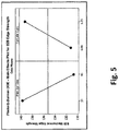
- the glass substrate with the edge finished-edge exhibits a mechanical edge strength exceeding 110 MPa as measured by a four point bend test.
- the mechanical edge strength may be about 130 MPa or greater.
- Glass sheets or substrates particularly relatively thick (e.g., 1.6 mm or greater) unstrengthened glass substrates, can be edge finished according to the embodiments described above.
- Such glass sheets or substrates may be used in Asymmetric Laminates as described herein.
- This failure mode was observed when subjecting an Asymmetric Laminate (comprising a 2.1 mm-thick SLG substrate, an PVB interlayer having a thickness of 0.8 mm, and a chemically strengthened glass substrate having a thickness of 0.7 mm) and a symmetric laminate (comprising two 2.1 mm-thick SLG substrates and an intervening PVB interlayer having a thickness of 0.8 mm).
- the Asymmetric Laminate showed greater failure at the edges of the laminate.
- Weibull analysis showed the Asymmetric Laminate exhibited a 35% reduction in mechanical edge strength compared with the symmetric laminate.
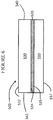
- the laminate 500 includes a first glass substrate 530 having a first major surface 532, an opposing second major surface 534 defining a first thickness, and a second strengthened glass substrate 510 having a first major surface 535, an opposing second major surface 537 defining a second thickness, wherein the first glass substrate has a first thickness greater than the strengthened glass substrate second thickness.
- the first glass substrate is unstrengthened (i.e., is not thermally, mechanically or chemically strengthened) but may be annealed.
- the laminate 500 includes an interlayer 520 is disposed between the first and second glass substrates.
- the laminate exhibits a mechanical edge strength of about 32.7 lbf or more, as measured by three point bend testing.
- the first glass substrate comprises an edge 540 that is edge-finished using the grind wheel and/or methods described herein, the edge-finished edge 540 exhibits a mechanical edge strength of about 80 MPa or greater, about 85 MPa or greater, about 90 MPa or greater, about 95 MPa or greater, about 100 MPa or greater, about 105 MPa or greater, about 110 MPa or greater, about 115 MPa or greater, about 120 MPa or greater, about 125 MPa or greater, about 130 MPa or greater, as measured by a four point bend test.
- the first glass substrate (which is thicker than the second glass substrate and is unstrengthened) exhibits a mechanical edge strength in a range from about 100 MPa to about 150 MPa, from about 110 MPa to about 150 MPa, from about 120 MPa to about 150 MPa, from about 130 MPa to about 150 MPa, from about 140 MPa to about 150 MPa, from about 100 MPa to about 140 MPa, from about 100 MPa to about 130 MPa, from about 100 MPa to about 120 MPa, from about 100 MPa to about 110 MPa, from about 120 MPa to about 140 MPa, or from about 120 MPa to about 130 MPa, as measured using a four-point bend test.
- the ratio of the first thickness to the second thickness is at least 10:1, or at least 9:1, or at least 8:1, or at least 7:1, or at least 6:1, or at least 5:1, or at least 4:1, or at least 3:1, or at least 2:1.
- the ratio of the first thickness to the second thickness is in the range of about 2:1 to about 10:1, or in the range of about 2:1 to about 9:1, or in the range of about 2:1 to about 8:1, or in the range of about 3:1 to about 10:1, or in the range of about 3:1 to about 9:1, or in the range of about 3:1 to about 8:1, or in the range of about 4:1 to about 10:1, or in the range of about 4:1 to about 9:1, or in the range of about 4:1 to about 8:1, or in the range of about 5:1 to about 10:1, or in the range of about 5:1 to about 9:1, or in the range of about 5:1 to about 8:1.
- the first glass substrate has a thickness that is about 1.6 mm or greater. In such embodiments, the first glass substrate has a thickness that is about 1.7 mm or greater, about 1.75 mm or greater, about 1.8 mm or greater, about 1.7 mm or greater, about 1.7 mm or greater, about 1.85 mm or greater, about 1.9 mm or greater, about 1.95 mm or greater, about 2 mm or greater, about 2.1 mm or greater, about 2.2 mm or greater, about 2.3 mm or greater, about 2.4 mm or greater, 2.5 mm or greater, 2.6 mm or greater, 2.7 mm or greater, 2.8 mm or greater, 2.9 mm or greater, 3 mm or greater, 3.2 mm or greater, 3.4 mm or greater, 3.5 mm or greater, 3.6 mm or greater, 3.8 mm or greater, 4 mm or greater, 4.2 mm or greater, 4.4 mm or greater, 4.6 mm or greater, 4.8
- the first glass substrate has a thickness in a range from about 1.6 mm to about 6 mm, from about 1.7 mm to about 6 mm, from about 1.8 mm to about 6 mm, from about 1.9 mm to about 6 mm, from about 2 mm to about 6 mm, from about 2.1 mm to about 6 mm, from about 2.2 mm to about 6 mm, from about 2.3 mm to about 6 mm, from about 2.4 mm to about 6 mm, from about 2.5 mm to about 6 mm, from about 2.6 mm to about 6 mm, from about 2.8 mm to about 6 mm, from about 3 mm to about 6 mm, from about 3.2 mm to about 6 mm, from about 3.4 mm to about 6 mm, from about 3.6 mm to about 6 mm, from about 3.8 mm to about 6 mm, from about 4 mm to about 6 mm, from about 1.6 mm to about 5.8 mm, from about 1.6 mm to about 5.6 mm, from
- the second glass ubstrate has a thickness thickness less than 1.6 mm (e.g., 1.55 mm or less, 1.5 mm or less, 1.45 mm or less, 1.4 mm or less, 1.35 mm or less, 1.3 mm or less, 1.25 mm or less, 1.2 mm or less, 1.15 mm or less, 1.1 mm or less, 1.05 mm or less, 1 mm or less, 0.95 mm or less, 0.9 mm or less, 0.85 mm or less, 0.8 mm or less, 0.75 mm or less, 0.7 mm or less, 0.65 mm or less, 0.6 mm or less, 0.55 mm or less, 0.
- 1.6 mm e.g., 1.55 mm or less, 1.5 mm or less, 1.45 mm or less, 1.4 mm or less, 1.35 mm or less, 1.3 mm or less, 1.25 mm or less, 1.2 mm or less, 1.15 mm or less, 1.1 mm or less, 1.
- the lower limit of thickness may be 0.1 mm, 0. 2mm or 0.3 mm.
- the thickness of the second glass substrate is in the range from about 0.1 mm to less than about 1.6 mm, from about 0.1 mm to about 1.5 mm, from about 0.1 mm to about 1.4 mm, from about 0.1 mm to about 1.3 mm, from about 0.1 mm to about 1.2 mm, from about 0.1 mm to about 1.1 mm, from about 0.1 mm to about 1 mm, from about 0.1 mm to about 0.9 mm, from about 0.1 mm to about 0.8 mm, from about 0.1 mm to about 0.7 mm, from about 0.1 mm, from about 0.2 mm to less than about 1.6 mm, from about 0.3 mm to less than about 1.6 mm, from about 0.4 mm to less than about 1.6 mm, from about 0.5 mm to less than about 1.6 mm, from about 0.6 mm to less than about 1.6 mm, from about 0.7 mm to less than about 1.6 mm, from about 0.8 mm to less than about 1.6 mm, from
- the laminate has a thickness of 6.85 mm or less, or 5.85 mm or less, where the thickness comprises the sum of thicknesses of the first glass substrate, the second glass substrate, and the interlayer.
- the laminate may have a thickness in the range of about 1.8 mm to about 6.85 mm, or in the range of about 1.8 mm to about 5.85 mm, or in the range of about 1.8 mm to about 5.0 mm, or 2.1 mm to about 6.85 mm, or in the range of about 2.1 mm to about 5.85 mm, or in the range of about 2.1 mm to about 5.0 mm, or in the range of about 2.4 mm to about 6.85 mm, or in the range of about 2.4 mm to about 5.85 mm, or in the range of about 2.4 mm to about 5.0 mm, or in the range of about 3.4 mm to about 6.85 mm, or in the range of about 3.4 mm to about 5.85 mm, or in the range of about 3.4 mm to about 5.85 mm
- the laminate exhibits radii of curvature that is less than 1000 mm, or less than 750 mm, or less than 500 mm, or less than 300 mm.
- the laminate, the first glass substrate and/or the second glass substrate are substantially free of wrinkles.
- the interlayer may include a single layer or multiple layers.
- the interlayer 520 (or layers thereof) may be formed polymers such as polyvinyl butyral (PVB), acoustic PBV (APVB), ionomers, ethylene-vinyl acetate (EVA) and thermoplastic polyurethane (TPU), polyester (PE), polyethylene terephthalate (PET) and the like.
- the thickness of the interlayer may be in the range from about 0.5 mm to about 2.5 mm, from about 0.8 mm to about 2.5 mm, from about 1 mm to about 2.5 mm or from about 1.5 mm to about 2.5 mm.
- one or more of interlayer 520, first glass substrate 430, and second glass substrate 510 comprise a first edge (e.g., 540) with a first thickness and a second edge (e.g., 542) opposite the first edge with a second thickness greater than the first thickness.
- the second glass substrate may be cold-formed (with an intervening interlayer).
- a second glass substrate 610 is laminated to a relatively thicker and curved first glass substrate 630 having an edge-finished edge 640.
- first glass substrate 630 includes a first surface 632 and a second surface 634 in contact with an interlayer 620
- the second glass substrate 610 includes a third surface 612 in contact with the interlayer 620 and a fourth surface 614.
- An indicator of a cold-formed laminate is the fourth surface 614 has a greater surface compressive stress (as described herein) than the third surface 612. Accordingly, a cold-formed laminate can comprise a high compressive stress level on fourth surface 614 making this surface more resistant to fracture.
- the respective compressive stresses in the third surface 612 and fourth surface 614 are substantially equal.
- the third surface 612 and the fourth surface 614 exhibit substantially equal compressive stress with respect to one another, prior to cold-forming.
- the compressive stress on the fourth surface 614 increases (i.e., the compressive stress on the fourth surface 614 is greater after cold-forming than before cold-forming).
- the cold-forming process increases the compressive stress of the glass substrate being shaped (i.e., the second glass substrate) to compensate for tensile stresses imparted during bending and/or forming operations.
- the cold-forming process causes the third surface of that glass substrate (i.e., the third surface 612) to experience tensile stresses, while the fourth surface of the glass substrate (i.e., the fourth surface 614) experiences compressive stresses.
- the third and fourth surfaces (612, 614) are already under compressive stress, and thus the third surface 612 can experience greater tensile stress. This allows for the strengthened second glass substrate 610 to conform to more tightly curved surfaces.
- the second glass substrate 610 has a thickness less than the first glass substrate 630. This thickness differential means the second glass susbtrate 610 is more flexible to conform to the shape of the first glass substrate 630.
- the cold-formed laminate 600 may be formed using an exemplary cold forming process that is performed at a temperature at or just above the softening temperature of the interlayer material (e.g., 420) (e.g., about 100 °C to about 120 °C), that is, at a temperature less than the softening temperature of the respective glass substrate.
- the interlayer material e.g., 420
- the softening temperature of the interlayer material e.g., 420
- the cold-formed laminate may be formed by: placing an interlayer between the first glass substrate (which is curved) and a second glass substrate (which may be flat) to form a stack; applying pressure to the stack to press the second glass substrate against the interlayer layer which is pressed against the first glass substrate; and heating the stack to a temperature below 400° C to form the cold-formed laminate in which the second glass substrate conforms in shape to the first glass substrate.
- a process can occur using a vacuum bag or ring in an autoclave or another suitable apparatus.
- the stress of an exemplary second glass substrate 610 may change from substantially symmetrical to asymmetrical according to some embodiments of the present disclosure.
- flat and “planar” are used interchangeably and mean a shape having curvature less than a curvature at which lamination defects are created due to curvature mismatch, when such a flat substrate is cold-formed to another substrate (i.e., a radius of curvature of greater than or equal to about 3 meters, greater than or equal to about 4 meters or greater than or equal to about 5 meters) or a curvature (of any value) along only one axis.
- a flat substrate has the foregoing shape when placed on a surface.
- complex curve and “complexly curved” mean a non-planar shape having curvature along two orthogonal axes that are different from one another.
- complexly curved shapes includes having simple or compound curves, also referred to as non-developable shapes, which include but are not limited to spherical, aspherical, and toroidal.
- the complexly curved laminates according to embodiments may also include segments or portions of such surfaces, or be comprised of a combination of such curves and surfaces.
- a laminate may have a compound curve including a major radius and a cross curvature.
- a complexly curved laminate according to one or more embodiments may have a distinct radius of curvature in two independent directions.
- complexly curved laminates may thus be characterized as having "cross curvature," where the laminate is curved along an axis (i.e., a first axis) that is parallel to a given dimension and also curved along an axis (i.e., a second axis) that is perpendicular to the same dimension.
- the curvature of the laminate can be even more complex when a significant minimum radius is combined with a significant cross curvature, and/or depth of bend.
- Some laminates may also include bending along axes that are not perpendicular to one another.
- the complexly-curved laminate may have length and width dimensions of 0.5 m by 1.0 m and a radius of curvature of 2 to 2.5 m along the minor axis, and a radius of curvature of 4 to 5 m along the major axis.
- the complexly-curved laminate may have a radius of curvature of 5 m or less along at least one axis.
- the complexly-curved laminate may have a radius of curvature of 5 m or less along at least a first axis and along the second axis that is perpendicular to the first axis.
- the complexly-curved laminate may have a radius of curvature of 5 m or less along at least a first axis and along the second axis that is not perpendicular to the first axis.
- the laminate has a complexly curved shape and may optionally be cold-formed.
- FIG. 9 shows a vehicle 700 comprising a body 710 defining an interior, at least one opening 720 in communication with the interior, and a window disposed in the opening, wherein the window comprises a laminate, according to one or more embodiments described herein.
- the laminate may form the sidelights, windshields, rear windows, windows, rearview mirrors, and sunroofs in the vehicle.
- the laminate 700 may form an interior partition (not shown) within the interior of the vehicle, or may be disposed on an exterior surface of the vehicle and form an engine block cover, headlight cover, taillight cover, or pillar cover.
- the vehicle may include an interior surface (not shown, but may include door trim, seat backs, door panels, dashboards, center consoles, floor boards, and pillars), and the laminate described herein is disposed on the interior surface.
- the interior surface includes a display and the laminate is disposed over the display.
- vehicle includes automobiles, rolling stock, locomotive, boats, ships, and airplanes, helicopters, drones, space craft and the like.
- the laminate is positioned within a vehicle such that the first glass substrate faces the exterior of the vehicle (and the second glass substrate is adjacent the interior 710).
- the second glass substrate of the laminate is in direct contact with the interior (i.e., the surface of the second glass substrate facing the interior is bare and is free of any coatings).
- the first glass substrate of the laminate is in direct contact with the exterior (i.e., the surface of the glass substrate facing the exterior is bare and is free of any coatings).
- the laminate is configured to be an architectural glazing
- the unstrengthened glass substrate defines an outer substrate which faces an outside environment of the architectural structure and the internal strengthened glass substrate defines an inner substrate which faces an interior of the architectural structure.
- the laminate may have additional coating or layers applied to the exposed surfaces, including but not limited to tints, anti-reflection coatings, anti-glare coatings, scratch resistant coatings, etc.
- the polymer interlayer can be modified to have one or more of the following properties: ultraviolet (UV) absorption, Infrared (IR) absorption, and IR reflection, acoustic control/dampening, adhesion promotion, and tint.
- UV ultraviolet
- IR Infrared
- IR reflection acoustic control/dampening
- adhesion promotion and tint
- the polymer interlayer can be modified by a suitable additive such as a dye, a pigment, dopants, etc. to impart the desired property.
- the unstrengthened glass substrate has a first thickness of 2.1 mm, 1.6 mm, or 1 mm and the strengthened glass substrate has a second thickness of 0.8 mm, 0.7 mm, 0.55 mm, 0.5 mm or 0.4 mm.
- the interlayer thickness is 0.76 mm.
- the materials for the first glass substrate and the second glass substrate may be varied.
- the term "glass substrate” includes an amorphous substrate, a crystalline substrate or a combination thereof.
- the materials for the unstrengthened glass substrate and the strengthened glass substrate may be SLG, alkali aluminosilicate glass, alkali containing borosilicate glass and/or alkali aluminoborosilicate glass or glass-ceramic (including Li 2 O-Al 2 O 3 -SiO 2 system (i.e. LAS-System) glass ceramics, MgO-Al 2 O 3 -SiO 2 System (i.e.
- MAS-System glass ceramics, glass ceramics including crystalline phases of any one or more of mullite, spinel, ⁇ -quartz, ⁇ -quartz solid solution, petalite, lithium disilicate, ⁇ -spodumene, nepheline, and alumina).
- the second glass substrate is strengthened to include a surface compressive stress (CS) that extends from a major surface to a depth of compression (DOC).
- CS surface compressive stress
- DOC depth of compression
- the compressive stress regions are balanced by a central portion exhibiting a tensile stress.
- the stress crosses from a positive (compressive) stress to a negative (tensile) stress.
- the second glass substrate may be strengthened mechanically by utilizing a mismatch of the coefficient of thermal expansion between portions of the article to create a compressive stress region and a central region exhibiting a tensile stress.
- the second glass substrate may be strengthened thermally by heating the glass to a temperature below the glass transition point and then rapidly quenching.
- the second glass substrate may be chemically strengthening by ion exchange.
- ions at or near the surface of the second glass substrate are replaced by - or exchanged with - larger ions having the same valence or oxidation state.
- ions in the surface layer of the second glass substrate and the larger ions are monovalent alkali metal cations, such as Li + , Na + , K + , Rb + , and Cs + .
- monovalent cations in the surface layer may be replaced with monovalent cations other than alkali metal cations, such as Ag + or the like.
- the monovalent ions (or cations) exchanged into the second glass substrate generate a stress.
- Ion exchange processes are typically carried out by immersing the second glass substrate in a molten salt bath (or two or more molten salt baths) containing the larger ions to be exchanged with the smaller ions in the second glass substrate.
- a molten salt bath or two or more molten salt baths
- aqueous salt baths may also be utilized.
- the composition of the bath(s) may include more than one type of larger ion (e.g., Na+ and K+) or a single larger ion.
- parameters for the ion exchange process including, but not limited to, bath composition and temperature, immersion time, the number of immersions of the glass substrate in a salt bath (or baths), use of multiple salt baths, additional steps such as annealing, washing, and the like, are generally determined by the composition of the second glass substrate (including the structure of the substrate and any crystalline phases present) and the desired DOC and CS of the second glass substrate that results from strengthening.
- Exemplary molten bath composition may include nitrates, sulfates, and chlorides of the larger alkali metal ion. Typical nitrates include KNO 3 , NaNO 3 , LiNO 3 , NaSO 4 and combinations thereof.
- the temperature of the molten salt bath typically is in a range from about 380°C up to about 450°C, while immersion times range from about 15 minutes up to about 100 hours depending on second glass substrate thickness, bath temperature and glass (or monovalent ion) diffusivity. However, temperatures and immersion times different from those described above may also be used.
- the second glass substrate may be immersed in a molten salt bath of 100% NaNO 3 , 100% KNO 3 , or a combination of NaNO 3 and KNO 3 having a temperature from about 370 °C to about 480 °C.
- the second glass substrate may be immersed in a molten mixed salt bath including from about 5% to about 90% KNO 3 and from about 10% to about 95% NaNO 3 .
- the second glass substrate may be immersed in a second bath, after immersion in a first bath.
- the first and second baths may have different compositions and/or temperatures from one another. The immersion times in the first and second baths may vary. For example, immersion in the first bath may be longer than the immersion in the second bath.
- the second glass substrate may be immersed in a molten, mixed salt bath including NaNO 3 and KNO 3 (e.g., 49%/51%, 50%/50%, 51%/49%) having a temperature less than about 420 °C (e.g., about 400 °C or about 380 °C). for less than about 5 hours, or even about 4 hours or less.
- a molten, mixed salt bath including NaNO 3 and KNO 3 (e.g., 49%/51%, 50%/50%, 51%/49%) having a temperature less than about 420 °C (e.g., about 400 °C or about 380 °C). for less than about 5 hours, or even about 4 hours or less.
- Ion exchange conditions can be tailored to provide a "spike” or to increase the slope of the stress profile at or near the surface of the resulting second glass substrate.
- the spike may result in a greater surface CS value.
- This spike can be achieved by single bath or multiple baths, with the bath(s) having a single composition or mixed composition, due to the unique properties of the glass compositions used in the second glass substrate described herein.
- the different monovalent ions may exchange to different depths within the second glass substrate (and generate different magnitudes stresses within the glass substrate at different depths).
- the resulting relative depths of the stress-generating ions can be determined and cause different characteristics of the stress profile.
- CS is measured using those means known in the art, such as by surface stress meter (FSM) using commercially available instruments such as the FSM-6000, manufactured by Orihara Industrial Co., Ltd. (Japan).
- FSM surface stress meter
- FSM-6000 manufactured by Orihara Industrial Co., Ltd. (Japan).
- SOC stress optical coefficient
- ASTM standard C770-98 (2013) entitled “Standard Test Method for Measurement of Glass Stress-Optical Coefficient ,” the contents of which are incorporated herein by reference in their entirety, and a bulk cylinder method.
- CS may be the "maximum compressive stress" which is the highest compressive stress value measured within the compressive stress layer.
- the maximum compressive stress is located at the surface of the glass substrate. In other embodiments, the maximum compressive stress may occur at a depth below the surface, giving the compressive profile the appearance of a "buried peak.”
- DOC may be measured by FSM or by a scattered light polariscope (SCALP) (such as the SCALP-04 scattered light polariscope available from Glasstress Ltd., located in Tallinn Estonia), depending on the strengthening method and conditions.
- SCALP scattered light polariscope
- FSM or SCALP may be used depending on which ion is exchanged into the glass substrate.
- FSM is used to measure DOC.
- SCALP is used to measure DOC.
- the DOC is measured by SCALP, since it is believed the exchange depth of sodium indicates the DOC and the exchange depth of potassium ions indicates a change in the magnitude of the compressive stress (but not the change in stress from compressive to tensile); the exchange depth of potassium ions in such glass a substrates is measured by FSM.
- the second glass substrate maybe strengthened to exhibit a DOC that is described a fraction of the thickness t of the second glass substrate (as described herein).
- the DOC may be equal to or greater than about 0.1t, equal to or greater than about 0.11t, equal to or greater than about 0.12t, equal to or greater than about 0.13t, equal to or greater than about 0.14t, equal to or greater than about 0.15t, equal to or greater than about 0.16t, equal to or greater than about 0.17t, equal to or greater than about 0.18t, equal to or greater than about 0.19t, equal to or greater than about 0.2t, equal to or greater than about 0.21t.
- the DOC may be in a range from about 0.08t to about 0.25t, from about 0.09t to about 0.25t, from about 0.18t to about 0.25t, from about 0.11t to about 0.25t, from about 0.12t to about 0.25t, from about 0.13t to about 0.25t, from about 0.14t to about 0.25t, from about 0.15t to about 0.25t, from about 0.08t to about 0.24t, from about 0.08t to about 0.23t, from about 0.08t to about 0.22t, from about 0.08t to about 0.21t, from about 0.08t to about 0.2t, from about 0.08t to about 0.19t, from about 0.08t to about 0.18t, from about 0.08t to about 0.17t, from about 0.08t to about 0.16t, or from about 0.08t to about 0.15t.
- the DOC may be about 20 ⁇ m or less. In one or more embodiments, the DOC may be about 40 ⁇ m or greater (e.g., from about 40 ⁇ m to about 300 ⁇ m, from about 50 ⁇ m to about 300 ⁇ m, from about 60 ⁇ m to about 300 ⁇ m, from about 70 ⁇ m to about 300 ⁇ m, from about 80 ⁇ m to about 300 ⁇ m, from about 90 ⁇ m to about 300 ⁇ m, from about 100 ⁇ m to about 300 ⁇ m, from about 110 ⁇ m to about 300 ⁇ m, from about 120 ⁇ m to about 300 ⁇ m, from about 140 ⁇ m to about 300 ⁇ m, from about 150 ⁇ m to about 300 ⁇ m, from about 40 ⁇ m to about 290 ⁇ m, from about 40 ⁇ m to about 280 ⁇ m, from about 40 ⁇ m to about 260 ⁇ m, from about 40 ⁇ m to about 250 ⁇ m, from about 40 ⁇ m to about 240 ⁇ m, from
- the strengthened second glass substrate may have a CS (which may be found at the surface of the second glass substrate) of about 400 MPa or greater, about 500 MPa or greater, about 600 MPa or greater, about 700 MPa or greater, about 800 MPa or greater, about 900 MPa or greater, about 930 MPa or greater, about 1000 MPa or greater, or about 1050 MPa or greater.
- CS which may be found at the surface of the second glass substrate
- the strengthened second glass substrate may have a maximum tensile stress or central tension (CT) of about 20 MPa or greater, about 30 MPa or greater, about 40 MPa or greater, about 45 MPa or greater, about 50 MPa or greater, about 60 MPa or greater, about 70 MPa or greater, about 75 MPa or greater, about 80 MPa or greater, or about 85 MPa or greater.
- CT maximum tensile stress or central tension
- the maximum tensile stress or central tension (CT) may be in a range from about 40 MPa to about 100 MPa.
- One example glass composition comprises SiO 2 , B 2 O 3 and Na 2 O, where (SiO 2 + B 2 O 3 ) ⁇ 66 mol. %, and Na 2 O ⁇ 9 mol. %.
- the glass composition includes at least 6 wt.% aluminum oxide.
- the substrate includes a glass composition with one or more alkaline earth oxides, such that a content of alkaline earth oxides is at least 5 wt.%.
- Suitable glass compositions in some embodiments, further comprise at least one of K 2 O, MgO, and CaO.
- the glass compositions used in the substrate can comprise 61-75 mol.% SiO 2 ; 7-15 mol.% Al 2 O 3 ; 0-12 mol.% B 2 O 3 ; 9-21 mol.% Na 2 O; 0-4 mol.% K 2 O; 0-7 mol.% MgO; and 0-3 mol.% CaO.
- a further example glass composition suitable for the substrate comprises: 60-70 mol.% SiO 2 ; 6-14 mol.% Al 2 O 3 ; 0-15 mol.% B 2 O 3 ; 0-15 mol.% Li 2 O; 0-20 mol.% Na 2 O; 0-10 mol.% K 2 O; 0-8 mol.% MgO; 0-10 mol.% CaO; 0-5 mol.% ZrO 2 ; 0-1 mol.% SnO 2 ; 0-1 mol.% CeO 2 ; less than 50 ppm As 2 O 3 ; and less than 50 ppm Sb 2 O 3 ; where 12 mol.% ⁇ (Li 2 O + Na 2 O + K 2 O) ⁇ 20 mol.% and 0 mol.% ⁇ (MgO + CaO) ⁇ 10 mol.%.
- a still further example glass composition suitable for the substrate comprises: 63.5-66.5 mol.% SiO 2 ; 8-12 mol.% Al 2 O 3 ; 0-3 mol.% B 2 O 3 ; 0-5 mol.% Li 2 O; 8-18 mol.% Na 2 O; 0-5 mol.% K 2 O; 1-7 mol.% MgO; 0-2.5 mol.% CaO; 0-3 mol.% ZrO 2 ; 0.05-0.25 mol.% SnO 2 ; 0.05-0.5 mol.% CeO 2 ; less than 50 ppm As 2 O 3 ; and less than 50 ppm Sb 2 O 3 ; where 14 mol.% ⁇ (Li 2 O + Na 2 O + K 2 O) ⁇ 18 mol.% and 2 mol.% ⁇ (MgO + CaO) ⁇ 7 mol.%.
- an alkali aluminosilicate glass composition suitable for the second glass substrate comprises alumina, at least one alkali metal and, in some embodiments, greater than 50 mol.% SiO 2 , in other embodiments at least 58 mol.% SiO 2 , and in still other embodiments at least 60 mol.% SiO 2 , wherein the ratio ((Al 2 O 3 + B 2 O 3 )/ ⁇ modifiers)>1, where in the ratio the components are expressed in mol.% and the modifiers are alkali metal oxides.
- This glass composition in particular embodiments, comprises: 58-72 mol.% SiO 2 ; 9-17 mol.% Al 2 O 3 ; 2-12 mol.% B 2 O 3 ; 8-16 mol.% Na 2 O; and 0-4 mol.% K 2 O, wherein the ratio((Al 2 O 3 + B 2 O 3 )/ ⁇ modifiers)>1.
- the second glass substrate may include an alkali aluminosilicate glass composition comprising: 64-68 mol.% SiO 2 ; 12-16 mol.% Na 2 O; 8-12 mol.% Al 2 O 3 ; 0-3 mol.% B 2 O 3 ; 2-5 mol.% K 2 O; 4-6 mol.% MgO; and 0-5 mol.% CaO, wherein: 66 mol.% ⁇ SiO 2 + B 2 O 3 + CaO ⁇ 69 mol.%; Na 2 O + K 2 O + B 2 O 3 + MgO + CaO + SrO > 10 mol.%; 5 mol.% ⁇ MgO + CaO + SrO ⁇ 8 mol.%; (Na 2 O + B 2 O 3 ) - Al 2 O 3 ⁇ 2 mol.%; 2 mol.% ⁇ Na 2 O - Al 2 O 3 ⁇ 6 mol.%; and 4 mol.% ⁇ (Na 2 O + B 2 O 3
- the second glass substrate may comprise an alkali aluminosilicate glass composition comprising: 2 mol% or more of Al 2 O 3 and/or ZrO 2 , or 4 mol% or more of Al 2 O 3 and/or ZrO 2 .
- compositions used for a second glass substrate may be batched with 0-2 mol. % of at least one fining agent selected from a group that includes Na 2 SO 4 , NaCl, NaF, NaBr, K 2 SO 4 , KCl, KF, KBr, and SnO 2 .
- Another reference exampleof the present disclosure relates to a method of manufacturing a laminate comprising arranging an unstrengthened glass substrate (i.e., the first glass substrate), an interlayer, and a strengthened glass substrate (i.e., the second glass substrate) in a stack.
- the laminate may be formed by placing the glass substrates and interlayer in a pre-press to tack the interlayer to the strengthened glass substrates. Tacking can include expelling most of the air from the interfaces and partially bonding the interlayer to the glass substrates.
- the interlayer may be heated to a temperature effective to soften the interlayer, which promotes a conformal mating of the interlayer to respective surfaces of the glass substrates.
- a lamination temperature can be about 140°C.
- the mobile polymer chains within the interlayer material develop bonds with the substrate surfaces, which promote adhesion. Elevated temperatures also accelerate the diffusion of residual air and/or moisture from the glass-polymer interface.
- the heating can be performed with the glass substrate(s) in contact with the interlayer under pressure.
- the application of pressure both promotes flow of the interlayer material, and suppresses bubble formation that otherwise could be induced by the combined vapor pressure of water and air trapped at the interfaces.
- a forming process can occur at or just above the softening temperature of the interlayer material (e.g., about 100 °C to about 120 °C), that is, at a temperature less than the softening temperature of the respective strengthened glass substrate(s).
- the heat and pressure can be simultaneously applied to the assembly in an autoclave.
- the stack of an external chemically strengthened glass substrate, an interlayer, and an internal chemically strengthened glass substrate may be placed within a vacuum bag or a vacuum ring for processing.
- the stack and vacuum bag or vacuum ring may be placed with the autoclave.
- the SLG substrates with an edge-finished edge were combined with a chemically strengthened glass substrate having a thickness of 0.7 mm, and an intervening interlayer.
- the mechanical edge strength of the laminate including a SLG substrate having an edge that was edge finished using the 400 mesh bronze grind wheel exhibited an edge strength of 26.9 pounds of force, as measured by the three point bend test.
- Examples L-M in Table 1 are comparative examples, which were 400 mesh wheels made with each metal bond and resin bond diamond abrasives.
- the edges of 2.1 mm thick SLG substrates were edge finished with each of Examples A-M.
- the edge strength of the substrates edge-finished using the abrasive particle compositions Table 1 was measured and compared to the edge strength of 2.1 mm thick SLG substrates that were edge-finished using a known standard 220 mesh grind bronze-bonded diamond grind wheels.
- the edge strength was measured using a four point bend test (ASTM C 158-02).
- the edge strength wasWeibull plotted (95% Confidence Interval). The Weibull Plot is shown in FIG. 4 .
- the presence of a primary abrasive with a primary particle size and a secondary abrasive with a secondary particle size less than or equal to the primary particle size in a grind wheel improves edge strength when compared to grind wheel data with only single particle size.
- results can further be improved by the presence of a tertiary abrasive having a tertiary particle size less than the secondary particle size.
- the tertiary abrasive particles act as a bond stiffener.
- FIG. 5 shows a Plackett-Burman plot demonstrating the added benefit of blending different sized abrasives in the composition of grind wheels designed to edge finish brittle materials such as SLG.
- FIG. 5 four point bend mechanical edge strength data is plotted for two blended composition wheels and compared to the metal bond diamond and resin bond diamond 400 mesh controls.
- blended abrasive wheels with primary particles and secondary particles outperformed comparative examples with only a single sized abrasive particle.
- size blending was kept constant at 70 volume percent primary size abrasive and 30 volume percent secondary size abrasive, however, other blend volumes are within the scope of this disclosure.
- the contribution of the tertiary diamond abrasive was not considered when determining volume fractions in size blended wheels.
Landscapes
- Engineering & Computer Science (AREA)
- Mechanical Engineering (AREA)
- Chemical & Material Sciences (AREA)
- Ceramic Engineering (AREA)
- Inorganic Chemistry (AREA)
- Polishing Bodies And Polishing Tools (AREA)
Claims (10)
- Schleifscheibe (410), aufweisend:eine Metallbindungs-Matrixstruktur (412);eine Vielzahl von primären Diamant-Schleifpartikeln (401) innerhalb der Matrixstruktur (412), die eine Primärpartikelgröße haben; undeine Vielzahl von sekundären Schleifpartikeln (402) innerhalb der Matrixstruktur (412), die eine Sekundärpartikelgröße haben, die kleiner als oder so groß wie die Primärpartikelgröße ist, wobei die primären Diamant-Schleifpartikel (401) oder sekundären Schleifpartikel (402) Kunstharzbindungs-Diamantpartikel aufweisen, dadurch gekennzeichnet, dassentweder die Vielzahl der primären Diamant-Schleifpartikel (401) Kunstharzbindungs-Diamantpartikel aufweist und die Vielzahl der sekundären Schleifpartikel (402) Metallbindungs-Diamantpartikel aufweist, oderdie Vielzahl der sekundären Schleifpartikel (402) Kunstharzbindungs-Diamantpartikel aufweist und die Vielzahl der primären Diamant-Schleifpartikel (401) Metallbindungs-Diamantpartikel aufweist.
- Schleifscheibe (410) nach Anspruch 1, wobei die Schleifscheibe (410) ein Schleifscheibenvolumen aufweist, wobei die Metallbindungs-Matrixstruktur (412) 60 Volumenprozent bis 90 Volumenprozent des Schleifscheibenvolumens ausmacht, und wobei die Vielzahl der primären Diamant-Schleifpartikel (401) und die Vielzahl der sekundären Schleifpartikel (402) 10 Volumenprozent bis 40 Volumenprozent des Schleifscheibenvolumens ausmachen.
- Schleifscheibe (410) nach einem der vorhergehenden Ansprüche, wobei die Metallbindungs-Matrixstruktur (412) Eisen aufweist.
- Schleifscheibe (410) nach einem der vorhergehenden Ansprüche, wobei die primären Diamant-Schleifpartikel (401) und die sekundären Schleifpartikel (402) ein Gesamt-Schleifpartikelvolumen aufweisen, wobei die primären Schleifpartikel (401) 51% bis 97% des Gesamt-Schleifpartikelvolumens und die sekundären Schleifpartikel (402) 2% bis 48% des Gesamt-Schleifpartikelvolumens ausmachen.
- Schleifscheibe (410) nach einem der vorhergehenden Ansprüche, darüber hinaus eine Vielzahl von tertiären Diamant-Schleifpartikeln innerhalb der Metallbindungs-Matrixstruktur aufweisend, wobei die Vielzahl der tertiären Diamant-Schleifpartikel eine Tertiärpartikelgröße haben, die kleiner als oder so groß wie die Sekundärpartikelgröße ist.
- Schleifscheibe (410) nach Anspruch 5, wobei die Primärpartikelgröße in einem Bereich von 30 Mikrometer bis 40 Mikrometer, die Sekundärpartikelgröße in einem Bereich von 20 Mikrometer bis 30 Mikrometer und die Tertiärpartikelgröße in einem Bereich von 1 Mikrometer bis 10 Mikrometer liegt.
- Schleifscheibe (410) nach Anspruch 5, wobei die Primärpartikelgröße in einem Bereich von 50 Mikrometer bis 60 Mikrometer, die Sekundärpartikelgröße in einem Bereich von 40 Mikrometer bis 50 Mikrometer und die Tertiärpartikelgröße in einem Bereich von 4 Mikrometer bis 8 Mikrometer liegt.
- Schleifscheibe (410) nach Anspruch 1, wobei die Primärpartikelgröße in einem Bereich von 30 Mikrometer bis 40 Mikrometer und die Sekundärpartikelgröße in einem Bereich von 15 Mikrometer bis 30 Mikrometer liegt.
- Schleifscheibe (410) nach Anspruch 8, darüber hinaus tertiäre Diamant-Schleifpartikel innerhalb der Metallbindungs-Matrixstruktur aufweisend, die eine Tertiärpartikelgröße haben, die kleiner als die Sekundärpartikelgröße ist.
- Schleifscheibe (410) nach Anspruch 9, wobei die Tertiärpartikelgröße in einem Bereich von 1 bis 10 Mikrometer liegt.
Applications Claiming Priority (2)
| Application Number | Priority Date | Filing Date | Title |
|---|---|---|---|
| US201662294146P | 2016-02-11 | 2016-02-11 | |
| PCT/US2017/017413 WO2017139608A1 (en) | 2016-02-11 | 2017-02-10 | Grinding wheel |
Publications (2)
| Publication Number | Publication Date |
|---|---|
| EP3414053A1 EP3414053A1 (de) | 2018-12-19 |
| EP3414053B1 true EP3414053B1 (de) | 2020-03-18 |
Family
ID=58108747
Family Applications (1)
| Application Number | Title | Priority Date | Filing Date |
|---|---|---|---|
| EP17706936.6A Active EP3414053B1 (de) | 2016-02-11 | 2017-02-10 | Schleifscheibe |
Country Status (6)
| Country | Link |
|---|---|
| US (1) | US20170232571A1 (de) |
| EP (1) | EP3414053B1 (de) |
| JP (1) | JP2019504775A (de) |
| KR (1) | KR20180108804A (de) |
| CN (1) | CN108770349A (de) |
| WO (1) | WO2017139608A1 (de) |
Families Citing this family (4)
| Publication number | Priority date | Publication date | Assignee | Title |
|---|---|---|---|---|
| CN113039040A (zh) * | 2018-10-04 | 2021-06-25 | 康宁公司 | 用于形成多区段显示器的系统和方法 |
| EP3986665A1 (de) * | 2019-06-20 | 2022-04-27 | Corning Incorporated | Verfahren und vorrichtung zur kantenbearbeitung hochmechanischer dünnglassubstrate |
| CN110181418A (zh) * | 2019-06-28 | 2019-08-30 | 江苏铁锚玻璃股份有限公司 | 具有渐变化槽口的c型磨轮及其制作方法 |
| CN116604427B (zh) * | 2023-05-25 | 2026-03-17 | 安徽省凤形新材料科技有限公司 | 一种高韧耐磨球铸造加工设备 |
Family Cites Families (12)
| Publication number | Priority date | Publication date | Assignee | Title |
|---|---|---|---|---|
| US3902873A (en) * | 1967-09-26 | 1975-09-02 | Ind Distributors 1946 Limited | Metal coated synthetic diamonds embedded in a synthetic resinous matrix bond |
| US3925035A (en) * | 1972-02-22 | 1975-12-09 | Norton Co | Graphite containing metal bonded diamond abrasive wheels |
| US4373934A (en) * | 1981-08-05 | 1983-02-15 | General Electric Company | Metal bonded diamond aggregate abrasive |
| US4525178A (en) * | 1984-04-16 | 1985-06-25 | Megadiamond Industries, Inc. | Composite polycrystalline diamond |
| US4883500A (en) * | 1988-10-25 | 1989-11-28 | General Electric Company | Sawblade segments utilizing polycrystalline diamond grit |
| US4923490A (en) * | 1988-12-16 | 1990-05-08 | General Electric Company | Novel grinding wheels utilizing polycrystalline diamond or cubic boron nitride grit |
| US9409280B2 (en) * | 1997-04-04 | 2016-08-09 | Chien-Min Sung | Brazed diamond tools and methods for making the same |
| US6319108B1 (en) * | 1999-07-09 | 2001-11-20 | 3M Innovative Properties Company | Metal bond abrasive article comprising porous ceramic abrasive composites and method of using same to abrade a workpiece |
| US20090017736A1 (en) * | 2007-07-10 | 2009-01-15 | Saint-Gobain Abrasives, Inc. | Single-use edging wheel for finishing glass |
| US8070558B2 (en) * | 2009-03-04 | 2011-12-06 | David Young | Porcelain epoxy flooring and method for producing the same |
| US8721392B2 (en) * | 2011-06-28 | 2014-05-13 | Corning Incorporated | Glass edge finishing method |
| US20140287658A1 (en) * | 2011-09-07 | 2014-09-25 | 3M Innovative Properties Company | Bonded abrasive article |
-
2017
- 2017-02-08 US US15/427,484 patent/US20170232571A1/en not_active Abandoned
- 2017-02-10 EP EP17706936.6A patent/EP3414053B1/de active Active
- 2017-02-10 JP JP2018541395A patent/JP2019504775A/ja not_active Abandoned
- 2017-02-10 CN CN201780011143.4A patent/CN108770349A/zh active Pending
- 2017-02-10 WO PCT/US2017/017413 patent/WO2017139608A1/en not_active Ceased
- 2017-02-10 KR KR1020187025775A patent/KR20180108804A/ko not_active Withdrawn
Non-Patent Citations (1)
| Title |
|---|
| None * |
Also Published As
| Publication number | Publication date |
|---|---|
| CN108770349A (zh) | 2018-11-06 |
| EP3414053A1 (de) | 2018-12-19 |
| US20170232571A1 (en) | 2017-08-17 |
| WO2017139608A1 (en) | 2017-08-17 |
| JP2019504775A (ja) | 2019-02-21 |
| KR20180108804A (ko) | 2018-10-04 |
Similar Documents
| Publication | Publication Date | Title |
|---|---|---|
| KR102048463B1 (ko) | 경-량 하이브리드 유리 적층체 | |
| JP6080279B2 (ja) | イオン交換ガラスを製造する方法および結果として得られた装置 | |
| EP2858820B1 (de) | Verbundglaskonstruktion für optimierte bruchleistung | |
| WO2017106081A1 (en) | Asymmetric glass laminates | |
| US20180200995A1 (en) | Strengthened asymmetric glass laminates | |
| CA2944082A1 (en) | Composite glass with thin inner pane | |
| EP3046761A1 (de) | Hybride leichtgewichtige glaslaminate | |
| JP2019194152A (ja) | 積層構造を備えている自動車 | |
| WO2012051038A1 (en) | Chemically-strengthened glass laminates | |
| EP3414053B1 (de) | Schleifscheibe | |
| US20160229155A1 (en) | Composite pane, composed of a polymeric pane and a glass pane | |
| WO2017070283A2 (en) | Asymmetric glass laminates exhibiting improved damage tolerance | |
| CN110944838A (zh) | 包括化学钢化的薄玻璃片材的层压窗玻璃 | |
| WO2019070788A1 (en) | GLASS LAMINATE HAVING LOW COMPRESSION STRENGTH, LARGE LAYER DEPTH, CHEMICALLY REINFORCED INTERNAL GLASS LAYER, AND METHOD THEREOF | |
| WO2020060748A1 (en) | Asymmetric glass laminates | |
| WO2020005639A1 (en) | Asymmetric glass laminates |
Legal Events
| Date | Code | Title | Description |
|---|---|---|---|
| STAA | Information on the status of an ep patent application or granted ep patent |
Free format text: STATUS: UNKNOWN |
|
| STAA | Information on the status of an ep patent application or granted ep patent |
Free format text: STATUS: THE INTERNATIONAL PUBLICATION HAS BEEN MADE |
|
| PUAI | Public reference made under article 153(3) epc to a published international application that has entered the european phase |
Free format text: ORIGINAL CODE: 0009012 |
|
| STAA | Information on the status of an ep patent application or granted ep patent |
Free format text: STATUS: REQUEST FOR EXAMINATION WAS MADE |
|
| 17P | Request for examination filed |
Effective date: 20180810 |
|
| AK | Designated contracting states |
Kind code of ref document: A1 Designated state(s): AL AT BE BG CH CY CZ DE DK EE ES FI FR GB GR HR HU IE IS IT LI LT LU LV MC MK MT NL NO PL PT RO RS SE SI SK SM TR |
|
| AX | Request for extension of the european patent |
Extension state: BA ME |
|
| DAV | Request for validation of the european patent (deleted) | ||
| DAX | Request for extension of the european patent (deleted) | ||
| REG | Reference to a national code |
Ref country code: DE Ref legal event code: R079 Ref document number: 602017013264 Country of ref document: DE Free format text: PREVIOUS MAIN CLASS: B24D0003060000 Ipc: B24D0005140000 |
|
| RIC1 | Information provided on ipc code assigned before grant |
Ipc: B24D 5/14 20060101AFI20190718BHEP Ipc: B24D 5/02 20060101ALI20190718BHEP Ipc: B24D 3/06 20060101ALI20190718BHEP Ipc: B24B 9/10 20060101ALI20190718BHEP |
|
| GRAP | Despatch of communication of intention to grant a patent |
Free format text: ORIGINAL CODE: EPIDOSNIGR1 |
|
| STAA | Information on the status of an ep patent application or granted ep patent |
Free format text: STATUS: GRANT OF PATENT IS INTENDED |
|
| INTG | Intention to grant announced |
Effective date: 20190916 |
|
| GRAS | Grant fee paid |
Free format text: ORIGINAL CODE: EPIDOSNIGR3 |
|
| GRAA | (expected) grant |
Free format text: ORIGINAL CODE: 0009210 |
|
| STAA | Information on the status of an ep patent application or granted ep patent |
Free format text: STATUS: THE PATENT HAS BEEN GRANTED |
|
| AK | Designated contracting states |
Kind code of ref document: B1 Designated state(s): AL AT BE BG CH CY CZ DE DK EE ES FI FR GB GR HR HU IE IS IT LI LT LU LV MC MK MT NL NO PL PT RO RS SE SI SK SM TR |
|
| REG | Reference to a national code |
Ref country code: GB Ref legal event code: FG4D |
|
| REG | Reference to a national code |
Ref country code: DE Ref legal event code: R096 Ref document number: 602017013264 Country of ref document: DE |
|
| REG | Reference to a national code |
Ref country code: AT Ref legal event code: REF Ref document number: 1245365 Country of ref document: AT Kind code of ref document: T Effective date: 20200415 Ref country code: IE Ref legal event code: FG4D |
|
| PG25 | Lapsed in a contracting state [announced via postgrant information from national office to epo] |
Ref country code: NO Free format text: LAPSE BECAUSE OF FAILURE TO SUBMIT A TRANSLATION OF THE DESCRIPTION OR TO PAY THE FEE WITHIN THE PRESCRIBED TIME-LIMIT Effective date: 20200618 Ref country code: RS Free format text: LAPSE BECAUSE OF FAILURE TO SUBMIT A TRANSLATION OF THE DESCRIPTION OR TO PAY THE FEE WITHIN THE PRESCRIBED TIME-LIMIT Effective date: 20200318 Ref country code: FI Free format text: LAPSE BECAUSE OF FAILURE TO SUBMIT A TRANSLATION OF THE DESCRIPTION OR TO PAY THE FEE WITHIN THE PRESCRIBED TIME-LIMIT Effective date: 20200318 |
|
| REG | Reference to a national code |
Ref country code: NL Ref legal event code: MP Effective date: 20200318 |
|
| PG25 | Lapsed in a contracting state [announced via postgrant information from national office to epo] |
Ref country code: HR Free format text: LAPSE BECAUSE OF FAILURE TO SUBMIT A TRANSLATION OF THE DESCRIPTION OR TO PAY THE FEE WITHIN THE PRESCRIBED TIME-LIMIT Effective date: 20200318 Ref country code: GR Free format text: LAPSE BECAUSE OF FAILURE TO SUBMIT A TRANSLATION OF THE DESCRIPTION OR TO PAY THE FEE WITHIN THE PRESCRIBED TIME-LIMIT Effective date: 20200619 Ref country code: LV Free format text: LAPSE BECAUSE OF FAILURE TO SUBMIT A TRANSLATION OF THE DESCRIPTION OR TO PAY THE FEE WITHIN THE PRESCRIBED TIME-LIMIT Effective date: 20200318 Ref country code: SE Free format text: LAPSE BECAUSE OF FAILURE TO SUBMIT A TRANSLATION OF THE DESCRIPTION OR TO PAY THE FEE WITHIN THE PRESCRIBED TIME-LIMIT Effective date: 20200318 Ref country code: BG Free format text: LAPSE BECAUSE OF FAILURE TO SUBMIT A TRANSLATION OF THE DESCRIPTION OR TO PAY THE FEE WITHIN THE PRESCRIBED TIME-LIMIT Effective date: 20200618 |
|
| REG | Reference to a national code |
Ref country code: LT Ref legal event code: MG4D |
|
| PG25 | Lapsed in a contracting state [announced via postgrant information from national office to epo] |
Ref country code: NL Free format text: LAPSE BECAUSE OF FAILURE TO SUBMIT A TRANSLATION OF THE DESCRIPTION OR TO PAY THE FEE WITHIN THE PRESCRIBED TIME-LIMIT Effective date: 20200318 |
|
| PG25 | Lapsed in a contracting state [announced via postgrant information from national office to epo] |
Ref country code: RO Free format text: LAPSE BECAUSE OF FAILURE TO SUBMIT A TRANSLATION OF THE DESCRIPTION OR TO PAY THE FEE WITHIN THE PRESCRIBED TIME-LIMIT Effective date: 20200318 Ref country code: CZ Free format text: LAPSE BECAUSE OF FAILURE TO SUBMIT A TRANSLATION OF THE DESCRIPTION OR TO PAY THE FEE WITHIN THE PRESCRIBED TIME-LIMIT Effective date: 20200318 Ref country code: PT Free format text: LAPSE BECAUSE OF FAILURE TO SUBMIT A TRANSLATION OF THE DESCRIPTION OR TO PAY THE FEE WITHIN THE PRESCRIBED TIME-LIMIT Effective date: 20200812 Ref country code: LT Free format text: LAPSE BECAUSE OF FAILURE TO SUBMIT A TRANSLATION OF THE DESCRIPTION OR TO PAY THE FEE WITHIN THE PRESCRIBED TIME-LIMIT Effective date: 20200318 Ref country code: EE Free format text: LAPSE BECAUSE OF FAILURE TO SUBMIT A TRANSLATION OF THE DESCRIPTION OR TO PAY THE FEE WITHIN THE PRESCRIBED TIME-LIMIT Effective date: 20200318 Ref country code: SM Free format text: LAPSE BECAUSE OF FAILURE TO SUBMIT A TRANSLATION OF THE DESCRIPTION OR TO PAY THE FEE WITHIN THE PRESCRIBED TIME-LIMIT Effective date: 20200318 Ref country code: SK Free format text: LAPSE BECAUSE OF FAILURE TO SUBMIT A TRANSLATION OF THE DESCRIPTION OR TO PAY THE FEE WITHIN THE PRESCRIBED TIME-LIMIT Effective date: 20200318 Ref country code: IS Free format text: LAPSE BECAUSE OF FAILURE TO SUBMIT A TRANSLATION OF THE DESCRIPTION OR TO PAY THE FEE WITHIN THE PRESCRIBED TIME-LIMIT Effective date: 20200718 |
|
| REG | Reference to a national code |
Ref country code: AT Ref legal event code: MK05 Ref document number: 1245365 Country of ref document: AT Kind code of ref document: T Effective date: 20200318 |
|
| REG | Reference to a national code |
Ref country code: DE Ref legal event code: R097 Ref document number: 602017013264 Country of ref document: DE |
|
| PLBE | No opposition filed within time limit |
Free format text: ORIGINAL CODE: 0009261 |
|
| STAA | Information on the status of an ep patent application or granted ep patent |
Free format text: STATUS: NO OPPOSITION FILED WITHIN TIME LIMIT |
|
| PG25 | Lapsed in a contracting state [announced via postgrant information from national office to epo] |
Ref country code: ES Free format text: LAPSE BECAUSE OF FAILURE TO SUBMIT A TRANSLATION OF THE DESCRIPTION OR TO PAY THE FEE WITHIN THE PRESCRIBED TIME-LIMIT Effective date: 20200318 Ref country code: AT Free format text: LAPSE BECAUSE OF FAILURE TO SUBMIT A TRANSLATION OF THE DESCRIPTION OR TO PAY THE FEE WITHIN THE PRESCRIBED TIME-LIMIT Effective date: 20200318 Ref country code: DK Free format text: LAPSE BECAUSE OF FAILURE TO SUBMIT A TRANSLATION OF THE DESCRIPTION OR TO PAY THE FEE WITHIN THE PRESCRIBED TIME-LIMIT Effective date: 20200318 Ref country code: IT Free format text: LAPSE BECAUSE OF FAILURE TO SUBMIT A TRANSLATION OF THE DESCRIPTION OR TO PAY THE FEE WITHIN THE PRESCRIBED TIME-LIMIT Effective date: 20200318 |
|
| 26N | No opposition filed |
Effective date: 20201221 |
|
| PG25 | Lapsed in a contracting state [announced via postgrant information from national office to epo] |
Ref country code: PL Free format text: LAPSE BECAUSE OF FAILURE TO SUBMIT A TRANSLATION OF THE DESCRIPTION OR TO PAY THE FEE WITHIN THE PRESCRIBED TIME-LIMIT Effective date: 20200318 |
|
| PG25 | Lapsed in a contracting state [announced via postgrant information from national office to epo] |
Ref country code: SI Free format text: LAPSE BECAUSE OF FAILURE TO SUBMIT A TRANSLATION OF THE DESCRIPTION OR TO PAY THE FEE WITHIN THE PRESCRIBED TIME-LIMIT Effective date: 20200318 |
|
| REG | Reference to a national code |
Ref country code: DE Ref legal event code: R119 Ref document number: 602017013264 Country of ref document: DE |
|
| PG25 | Lapsed in a contracting state [announced via postgrant information from national office to epo] |
Ref country code: MC Free format text: LAPSE BECAUSE OF FAILURE TO SUBMIT A TRANSLATION OF THE DESCRIPTION OR TO PAY THE FEE WITHIN THE PRESCRIBED TIME-LIMIT Effective date: 20200318 |
|
| GBPC | Gb: european patent ceased through non-payment of renewal fee |
Effective date: 20210210 |
|
| REG | Reference to a national code |
Ref country code: BE Ref legal event code: MM Effective date: 20210228 |
|
| PG25 | Lapsed in a contracting state [announced via postgrant information from national office to epo] |
Ref country code: CH Free format text: LAPSE BECAUSE OF NON-PAYMENT OF DUE FEES Effective date: 20210228 Ref country code: LU Free format text: LAPSE BECAUSE OF NON-PAYMENT OF DUE FEES Effective date: 20210210 Ref country code: LI Free format text: LAPSE BECAUSE OF NON-PAYMENT OF DUE FEES Effective date: 20210228 |
|
| PG25 | Lapsed in a contracting state [announced via postgrant information from national office to epo] |
Ref country code: IE Free format text: LAPSE BECAUSE OF NON-PAYMENT OF DUE FEES Effective date: 20210210 Ref country code: GB Free format text: LAPSE BECAUSE OF NON-PAYMENT OF DUE FEES Effective date: 20210210 Ref country code: FR Free format text: LAPSE BECAUSE OF NON-PAYMENT OF DUE FEES Effective date: 20210228 Ref country code: DE Free format text: LAPSE BECAUSE OF NON-PAYMENT OF DUE FEES Effective date: 20210901 |
|
| PG25 | Lapsed in a contracting state [announced via postgrant information from national office to epo] |
Ref country code: BE Free format text: LAPSE BECAUSE OF NON-PAYMENT OF DUE FEES Effective date: 20210228 |
|
| PG25 | Lapsed in a contracting state [announced via postgrant information from national office to epo] |
Ref country code: CY Free format text: LAPSE BECAUSE OF FAILURE TO SUBMIT A TRANSLATION OF THE DESCRIPTION OR TO PAY THE FEE WITHIN THE PRESCRIBED TIME-LIMIT Effective date: 20200318 |
|
| PG25 | Lapsed in a contracting state [announced via postgrant information from national office to epo] |
Ref country code: HU Free format text: LAPSE BECAUSE OF FAILURE TO SUBMIT A TRANSLATION OF THE DESCRIPTION OR TO PAY THE FEE WITHIN THE PRESCRIBED TIME-LIMIT; INVALID AB INITIO Effective date: 20170210 |
|
| PG25 | Lapsed in a contracting state [announced via postgrant information from national office to epo] |
Ref country code: MK Free format text: LAPSE BECAUSE OF FAILURE TO SUBMIT A TRANSLATION OF THE DESCRIPTION OR TO PAY THE FEE WITHIN THE PRESCRIBED TIME-LIMIT Effective date: 20200318 |
|
| PG25 | Lapsed in a contracting state [announced via postgrant information from national office to epo] |
Ref country code: TR Free format text: LAPSE BECAUSE OF FAILURE TO SUBMIT A TRANSLATION OF THE DESCRIPTION OR TO PAY THE FEE WITHIN THE PRESCRIBED TIME-LIMIT Effective date: 20200318 |
|
| PG25 | Lapsed in a contracting state [announced via postgrant information from national office to epo] |
Ref country code: MT Free format text: LAPSE BECAUSE OF FAILURE TO SUBMIT A TRANSLATION OF THE DESCRIPTION OR TO PAY THE FEE WITHIN THE PRESCRIBED TIME-LIMIT Effective date: 20200318 |