EP3414207B1 - Härtungsofen und verfahren zur härtung eines glasobjekts und das glasobjekt - Google Patents
Härtungsofen und verfahren zur härtung eines glasobjekts und das glasobjekt Download PDFInfo
- Publication number
- EP3414207B1 EP3414207B1 EP17710053.4A EP17710053A EP3414207B1 EP 3414207 B1 EP3414207 B1 EP 3414207B1 EP 17710053 A EP17710053 A EP 17710053A EP 3414207 B1 EP3414207 B1 EP 3414207B1
- Authority
- EP
- European Patent Office
- Prior art keywords
- glass object
- glass
- turning
- heating
- tempering
- Prior art date
- Legal status (The legal status is an assumption and is not a legal conclusion. Google has not performed a legal analysis and makes no representation as to the accuracy of the status listed.)
- Active
Links
Images





Classifications
-
- C—CHEMISTRY; METALLURGY
- C03—GLASS; MINERAL OR SLAG WOOL
- C03B—MANUFACTURE, SHAPING, OR SUPPLEMENTARY PROCESSES
- C03B27/00—Tempering or quenching glass products
- C03B27/04—Tempering or quenching glass products using gas
- C03B27/06—Tempering or quenching glass products using gas for glass products other than flat or bent glass plates, e.g. hollow glassware, lenses
-
- C—CHEMISTRY; METALLURGY
- C03—GLASS; MINERAL OR SLAG WOOL
- C03B—MANUFACTURE, SHAPING, OR SUPPLEMENTARY PROCESSES
- C03B27/00—Tempering or quenching glass products
-
- C—CHEMISTRY; METALLURGY
- C03—GLASS; MINERAL OR SLAG WOOL
- C03B—MANUFACTURE, SHAPING, OR SUPPLEMENTARY PROCESSES
- C03B35/00—Transporting of glass products during their manufacture, e.g. hot glass lenses, prisms
- C03B35/005—Transporting hot solid glass products other than sheets or rods, e.g. lenses, prisms, by suction or floatation
-
- C—CHEMISTRY; METALLURGY
- C03—GLASS; MINERAL OR SLAG WOOL
- C03B—MANUFACTURE, SHAPING, OR SUPPLEMENTARY PROCESSES
- C03B35/00—Transporting of glass products during their manufacture, e.g. hot glass lenses, prisms
- C03B35/04—Transporting of hot hollow or semi-hollow glass products
-
- C—CHEMISTRY; METALLURGY
- C03—GLASS; MINERAL OR SLAG WOOL
- C03B—MANUFACTURE, SHAPING, OR SUPPLEMENTARY PROCESSES
- C03B35/00—Transporting of glass products during their manufacture, e.g. hot glass lenses, prisms
- C03B35/26—Transporting of glass tubes or rods
Definitions
- the present invention concerns a tempering furnace for tempering a glass object, a method of tempering a glass object, as well as a corresponding glass object.
- the invention concerns glass objects for well tools, which are applicable in oil and/or gas wells, wherein the glass object initially provides a pressure tight barrier for the fluid in the well, and, wherein the barrier easily may be removed by crushing the glass object.
- glass objects capable of withstanding high pressure differences have different fields of application, such as for instance inspection glass in nuclear power plants, portholes in diving bells, submarines, lenses of underwater cameras, etc.
- the invention concerns a method of tempering a glass object.
- tempering of glass takes place by heating the glass to a specific temperature range, and, then the glass is cooled again. This causes compression stress and tensile stress in different areas of the glass. Tempering of glass provides the glass with (at least) two features compared to non-tempered glass:
- the first feature is important in for instance windows in deep-water equipment.
- glass like this is tempered lying on a plate, or on rollers in a furnace; whereafter heat is applied and the glass is heated in a certain period of time before the glass is cooled again, where the cooling process preferably is fast.
- the object of the invention is to provide an improved tempering furnace for tempering glass objects, and an improved method of tempering glass objects.
- the object is to produce tempered glass capable of withstanding higher pressure, and, wherein, the glass, together with the fastening of the glass, is capable of withstanding higher pressure at higher temperatures.
- Another object is to obtain more even distribution of heat during heating and cooling, because it is believed this would provide more uniformly tempered glass, and, that this contributes to increase the maximal strength of the glass. In addition, it is an object to cool the glass object faster, because it is believed that this would contribute to increase the maximal strength of the glass.
- handling here, it is meant for instance to lift the glass from a heating station, and then transfer the glass in a heated state to a cooling station.
- a tempering furnace for tempering a glass object for providing a crushable, pressure tight barrier for a fluid in an oil and/or gas well wherein the glass object comprises a circular surface and chamfered surfaces, comprising:
- the heating device and cooling device may be the same device.
- the glass object may be situated inside the housing during heating or cooling, or, during both heating and cooling.
- the tempering furnace may comprise several housings - a first housing for heating, and a second housing for cooling.
- the housing may be a closed housing, which encloses the glass object inside, or it can be a partly closed housing only enclosing parts of the glass object.
- the turning device is configured to counteract the effect of gravity on the glass object when the glass object has been heated to its softening phase.
- softening phase it is meant that the glass object has been heated to a temperature higher than the glass transition temperature, but lower than the melting temperature.
- the heating device and/or cooling device comprise a fluid spray device for spraying a heating and/or cooling fluid towards the glass object, respectively.
- the fluid spray device has been configured at least to contribute to turning and/or supporting the glass object.
- fluid When fluid is sprayed towards the glass object in a certain amount and/or with a certain pressure, this will apply a force onto the glass object. Consequently, the glass object may be supported by spraying two fluid streams against opposite sides of the glass object.
- Rotation about a single axis is considered to represent a first type of turning.
- Turning may also be different from rotation.
- the cylindrical surface or the chamfered surfaces of the glass object are provided in contact with a conveyor belt provided around the rollers and the glass object.
- the turning device comprises a transporting device for transporting and turning the glass object along a path.
- This path does not need to be rotation about a single axis, and consequently, this may be considered to represent a second type of turning.
- the turning device is provided for turning a plurality of glass objects.
- the present invention concerns a method of tempering a glass object for providing a crushable, pressure tight barrier for a fluid in an oil and/or gas well, comprising:
- the method comprises the following step:
- the method comprises the following step:
- the present invention concerns a glass object tempered in accordance with the method above.
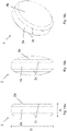
- the gravitational forces make a glass object 2 (e.g. as shown in Fig. 11a or 14a ) lying with one side 2b against a plate in a tempering furnace to change shape, because the part of the glass object 2 facing the plate achieves a larger diameter than the part of the glass object facing up from the plate.
- a glass object 2 e.g. as shown in Fig. 11a or 14a
- US 2 239 796 A discloses a method of tempering a tubular body of glass, which includes heating the glass to a selected temperature, rotating the body about an axis concentric to its bore and alternately introducing a cooling medium into opposite ends of the bore thereof. It further discloses a tempering apparatus which includes rotatable members for supporting a tubular glass body in rolling contact therewith, nozzles for directing a cooling medium along the bore wall of the body in a direction parallel to the bore thereof, and means for centering said nozzles with respect to the bore of the body.
- WO 2005/049961 A1 discloses a device of a test plug used in wells such as oil and gas wells and in water wells. It further discloses a method of tempering the glass object in order to obtain strength, toughness and good crushing characteristics. To obtain a satisfactory seal between each glass disc and between the outer surfaces of the glass and the inner wall of the pipe, the glass ought to be polished. This gives a good fit between glass and metal, i. e. a satisfactory seal between each glass plate and between the outer surface of the glass and the metal of the inner pipe wall.
- tempering glass at temperatures at which the glass is in its softening phase has largely been avoided.
- glass objects tempered in accordance with the prior art have alternatively been grinded or polished to obtain a precise shape adapted to the attachment. Such a grinding or polishing will reduce the strength of the glass object, and, consequently, is not desired.
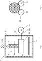
- the tempering furnace 1 comprises a housing 2.
- the housing 10 is preferably isolated, and, further, has a closed and open state. In the closed state, the housing is preferably relatively tight, such that the heating process and cooling process may take place in an energy efficient manner. In the open state, it is relatively easy to remove and insert glass objects 2 in the tempering furnace 1. Opening/closing may be performed by the housing being divided into two parts, which are held together in closed state and displaced away from each other in open state, or, by providing a hatch or door or the like into the tempering furnace. Further, the housing 10 comprises a heating device 12 for heating the glass object 2, as well as a cooling device 16 for cooling the glass object 2.
- the heating device 12 is a heating element provided inside the housing 10, under the glass object 2.
- the heating element may be supplied with electrical power; it may be heated when heated fluid, such as pre-heated pressurized air, is circulated through the heating element.
- the tempering furnace 10 comprises a thermostat inside the housing 10 connected to a temperature actuating device (not shown) on the outside of the housing 10 for controlling the heating device 12 such that control of the tempering temperature is obtained.
- the power of the heating device 12 may be controlled by a power actuating device (not shown) to control how fast the heating proceeds.
- the cooling device 16 is provided in an upper end of the housing 10, and comprises a fan F having nozzles capable of spraying cooling cold fluid (e.g. air or another gas, alternatively a liquid such as water) on to the glass object.
- the fluid can also be a mixture of air and water/liquid droplets which evaporate when hitting the glass surface, and which draws the evaporating heat from the glass such that a very fast cooling takers place.
- the tempering furnace 1 comprises a turning device 20 provided for turning the glass object 2 inside the housing 10.
- the turning device 20 is configured to counteract the effect of gravity on the glass object 2 when the glass object 2 is heated to its softening phase.
- a glass object will have to be maintained in a similar position for a certain time period before the effects of gravity becomes visible in the shape of the glass.
- this will be dependent on type of glass material and temperature.
- the invention uses the turning device 20. Several relevant variants of this turning device will be described below.
- Optical glass is in this so-called softening phase form a temperature of about 450 degrees and higher.
- the heating preferably takes place inside the housing 10.
- the cooling preferably takes place inside the housing 10; however, the housing 10, or parts of the housing 10, may be removed by moving the walls away from the glass object during the cooling.
- the turning device 20 is here provided for rotating the glass object 2 inside the housing 10.
- the turning device 20 here comprises a first rotatable roller 21 and a second rotatable roller 22 configured for rotating the glass object 2.
- One of the rollers 21, alternatively both the rollers 21, 22, may be connected to a motor 26 via a shaft 25 for rotating the roller 21 about the axis R1 and the glass object about the axis R2.
- the cylindrical surface 2a of the glass object 2 is provided in contact with the first and second rotating rollers 21, 22.
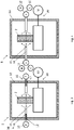
- the heating device 12 and cooling device 16 comprise several common elements in the form of a fluid spray device comprising a fan or pump 13, a fluid guide 14, and nozzles directed 15 directed to the glass object 2 inside the tempering furnace 1.
- the heating device 12 is here indicated as a heating element in the fluid guide.
- Fig. 4 corresponds to Fig. 3
- the pump device or fan device 13 is here coupled to a hot H and a cold C fluid source, which are used during heating and cooling, respectively.
- the nozzles 15 are directed towards the side surfaces 2b of the glass object to obtain a fast heating/cooling.
- a further function may be that they contribute to supporting the glass object 2, such that it does not topple; this may be especially suitable for glass objects having large diameter D and small height H (see Fig. 14a ).
- Fig. 5 and 6 show an alternative embodiment of the turning device 20 shown in Fig. 1 and 2 .
- a conveyor belt 27 is provided around the rollers 21, 22 and the glass object 2 to increase the friction between the glass object 2 and the turning device 20.
- a third roller 23 is shown; which is arranged above the glass object 2.
- the roller 23 may be used for stabilizing the glass object; i.e. avoid toppling during rotation.
- the third roller 23 may be used in other embodiments as well.
- the turning device 20 comprises contact elements 28a, 28b, 28c, wherein the contact elements hold the glass object between each other.
- the contact elements 28a, 28b, 28c are attached via strut 29 to the shaft 25, and to the motor 26.
- the glass object 2 is rotated about the same axis R1 as the rotational axis of the motor.
- the shafts 8a, 8b, and 8c may be provided in rotation such that the points of contact between the axis and the glass are not the same during the complete operation. In this way, the risk of obtaining dents or irregularities in the glass object is reduced.
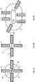
- the turning device 20 comprises a transporting device 24 attached to four glass objects for transporting and turning the glass object 2 in a path B.
- the path B has a rotational axis R1. In this case, all the glass objects will be turned similarly.
- Fig. 9b the transporting device 24 is rotated about an axis R1 different from the axis R1 of Figure 9a .
- the glass objects are rotated differently; however, there will still be a turning of the glass obj ects.
- the turning device 20 comprises a transporting device 24 turning the glass objects in an oval-like or oblong path B.
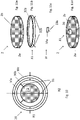
- the turning device 12 comprises a first support ring 30a attached to the glass object 2.
- a second support ring 30b is rotatable attached to the first support ring 30a by a first rotational axis R1, wherein the diameter of the second support ring 30b is larger than the diameter of the first support ring 30a.
- a third support ring 30c is rotatable attached to the second support ring 30b by a second rotational axis R2 different from the first rotational axis R1, wherein the diameter of the third support ring 30c is larger than the diameter of the second support ring 30b.
- the first and second rotational axis R1, R2 intersect close to the center of the support rings 30a, 30b; i.e. close to the center of the glass object 2.
- the rings are freely rotatable to each other, and the turning takes place by the fluid spray devices 13, 14, 15 being configured to rotate the support rings, and, thus, the glass object 2 in relation to each other, by fluid being sprayed towards the glass object 2 and/or the rings 30a, 30b, 30c; whereafter at least the first of the rings is set into rotation, and thus, the glass object 2 is rotated.
- FIG. 11b, 11c, and 11d wherein different attachment devices 31 for attaching the turning device 12 to the glass object 2 is shown.
- the attachment devices 31 are considered part of the turning device 20.
- the attachment device 31 of Figure 11b comprises a ring 32a for arrangement around the surface 2a of the glass object 2 (see, Fig.11a ), and, possibly strut 32b for attaching the ring 32a to other parts of the turning device 20.
- the attachment device 31 of Fig. 11c comprises a ring element 33a for attachment to the surface 2a; e.g. with an adhesive or by several such ring elements 33a being pressed against the surface 2a at different areas around the surface 2a.
- strut 33b may possibly be used.
- the attachment device 31 of Fig. 11d comprises an attachment device 34 for attachment to the surface 2b of the glass object 2; e.g. by an adhesive.
- the attachment device 34 may for instance be circular, and is put onto or coupled to a roller, for in this manner to achieve that the surface 2b is in contact with heating/cooling fluid during the complete process.
- Fig. 12 shows a tempering furnace 1 corresponding to Fig. 1 .
- a tempering furnace 1 corresponding to Fig. 1 .
- several glass objects are tempered; also a glass object having height H larger than diameter D.
- glass objects of different sizes should not be tempered in the same process, because larger objects will generally require heating and cooling for a longer time.
- Fig. 13a, 13b, and 13c show the turning device 20 for a glass object comprising a cylindrical part 2 with a large diameter, and a cylindrical part 2e with a relatively smaller diameter.
- rollers 21, 22 can be used for supporting and rotating the larger cylindrical part 2, as in Fig.2 , while a third roller 23 having a larger diameter may be used to support the cylindrical part 2e having the smaller diameter.
- the third roller 23 is coupled to the motor 25.
- Fig. 13d shows an alternative embodiment of Fig. 13a-c .
- two small rollers 23a, 23b for supporting the cylindrical part 2e, with relatively smaller diameter, are used.
- Fig. 13e shows a turning device 20, wherein a conveyor belt 27 is suspended from two rotating rollers 21, 22. The glass object 2 is then arranged suspended from the conveyor belt 27.
- An advantage of the present invention is that it is possible to achieve tempering of glass objects having two convex surfaces 2b, as shown in Fig. 14b, 14c .
- at least one of the surfaces 2b have had to be plane to be arranged on the plane base in tempering furnaces in accordance with the prior art.
- Fig. 15 shows a roller 21 wherein only the chamfered surfaces 2c are in contact with the roller.
- the roller 21 has a substantial hourglass shape.
- the rear roller 22 (not shown in Fig. 15 ) preferably also has an hourglass shape.
- the surface 2a is not in contact with the roller(s).
- Fig. 16 shows a turning device 20 comprising a robotic arm 39, and an attachment device 31, which can turn the glass object 2 inside a tempering furnace.
- the complete robotic arm may be inside the tempering furnace; parts of the robotic arm may also be outside the tempering furnace 1.
- the robotic arm may rotate the glass object around the axis R1; however, it is also possible to move the glass object along the lines L1, L2 in addition to rotation.
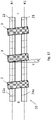
- Fig. 17 shows a turning device 20, seen from above, wherein rollers 21, 22 comprise chamfered or spirally shaped slots 21a, 22a having an angle A to the axis V perpendicular to the rotation axis R1, R2.
- the angle A may for instance be 1-10 degrees; and thus, the glass objects are transported linearly in the path B.
- This principle may be used in a production process in which the glass objects are first transported into a hot area, and then into a cold area. Along the complete path B, the glass objects will be rotated.
- the heating takes place inside the housing 10 for energy efficient heating.
- the cooling may take place inside the same housing 10; however, in a distance from the place of heating, or on the outside of the housing 10 - either in a further housing arranged adjacent to the first housing 10, or freely inside the production facility. Then, the walls of the housing or housings may be elevated or lowered to allow the glass objects to pass out of and into the housings from its position along the path B.
- Fig 18 shows an alternative to Fig. 5 above.
- the turning device 20 comprises three roller devices 21, 22, 23, as well as a conveyor belt arranged around the roller devices such that the conveyor belt comes into contact with the glass object 2 at three different areas. Rotation of at least one of the rollers will rotate the belt, and, thus, also, the glass object.
- Fig. 19 shows an alternative tempering furnace, which generally corresponds to Fig. 4 ; however, wherein the turning device 20 comprises one or more lower nozzles F supplied with fluid from a hot fluid source H, and a cold fluid source C, used for heating and cooling, respectively.
- the fluid streams from below and upwards, and creates a so-called fluidized bed, on which the glass object rests; wherein the fluid stream may be varied such that the glass object 2 is turned.
- the tempering furnace may comprise an upper nozzle supplied with corresponding hot and cold fluid.
- rollers 21, 22, 23, 23a, 23b need to be connected to a motor; of course, alternatively, more rollers may be connected to the motor, a separate motor, or to other rollers, such that more of the rollers rotate.
- optimal tempering is decided by parameters such as turning speed (e.g. rotation speed, transportation speed, or other types of turning), the glass material of the glass object, tempering temperature, tempering time, cooling time, size of the glass objects, etc.
- turning speed e.g. rotation speed, transportation speed, or other types of turning
- the glass material of the glass object e.g. tempering temperature, tempering time, cooling time, size of the glass objects, etc.
- the cooling devices may also comprise bringing a cold, solid material into contact with the glass object, e.g. cold mats, etc.
- a cold, solid material may be objects made from graphite.
- choice of material for turning device, tempering furnace, cooling device, and heating device need to be adapted to the temperatures in question, about 400 - about 900 °C.
- parts containing precision mechanics and electrical components are placed outside the housing 10 of the tempering furnace, such that these parts are shielded from the highest temperatures.
Landscapes
- Chemical & Material Sciences (AREA)
- Engineering & Computer Science (AREA)
- Materials Engineering (AREA)
- Organic Chemistry (AREA)
- Physics & Mathematics (AREA)
- Thermal Sciences (AREA)
- Re-Forming, After-Treatment, Cutting And Transporting Of Glass Products (AREA)
- Glass Compositions (AREA)
- Joining Of Glass To Other Materials (AREA)
- Heating, Cooling, Or Curing Plastics Or The Like In General (AREA)
- Electric Stoves And Ranges (AREA)
Claims (9)
- Härtungsofen (1) zum Härten eines Glasobjekts (2) zum Bereitstellen einer zerbrechbaren, druckdichten Barriere für ein Fluid in einem Öl- und/oder Gasbohrloch, wobei das Glasobjekt (2) eine kreisförmige Fläche (2a) und abgeschrägte Flächen (2c) umfasst,
umfassend:- ein Gehäuse (10),- eine Heizvorrichtung (12) zum Erwärmen des Glasobjekts (2), wenn sich das Glasobjekt (2) im Inneren des Gehäuses (10) befindet,- eine Kühlvorrichtung (16) zum Kühlen des Glasobjekts (2), wenn sich das Glasobjekt (2) im Inneren des Gehäuses (10) befindet,eine Drehvorrichtung (20), die zum Rotieren des Glasobjekts (2) im Inneren des Gehäuses (10) bereitgestellt ist; wobei die Drehvorrichtung (20) eine erste rotierbare Rolle (21) und eine zweite rotierbare Rolle (22) umfasst, die zum Rotieren des Glasobjekts (2) konfiguriert sind;dadurch gekennzeichnet, dass die Drehvorrichtung (20) dazu konfiguriert ist, der Wirkung von Gravitationskräften auf das Glasobjekt (2) entgegenzuwirken, wenn das Glasobjekt (2) auf seine Erweichungsphase erwärmt wurde;wobei die abgeschrägten Flächen (2c) des Glasobjekts (2) in Kontakt mit der ersten und der zweiten rotierenden Rolle (21, 22) bereitgestellt sind,wobei die erste und die zweite rotierende Rolle (21, 22) eine Sanduhrform zum Kontakt mit den abgeschrägten Flächen (2c) aufweisen. - Härtungsofen (1) nach einem der vorstehenden Ansprüche,
wobei die Heizvorrichtung (12) und/oder die Kühlvorrichtung (16) eine Fluidsprühvorrichtung (13, 14, 15) zum Sprühen eines Heiz- bzw. Kühlfluids auf das Glasobjekt (2) umfasst/umfassen. - Härtungsofen (1) nach Anspruch 2,
wobei die Fluidsprühvorrichtung (13, 14, 15) dazu konfiguriert ist, zum Drehen und/oder Lagern des Glasobjekts (2) zumindest beizutragen. - Härtungsofen (1) nach Anspruch 1,
wobei die zylinderförmige Fläche (2a) oder die abgeschrägten Flächen (2c) des Glasobjekts (2) in Kontakt mit einem Förderband (27) bereitgestellt ist, das um die Rollen (21, 22) und das Glasobjekt (2) bereitgestellt ist. - Härtungsofen (1) nach einem der vorstehenden Ansprüche,
wobei die Drehvorrichtung (12) zum Drehen einer Vielzahl von Glasobjekten (2) bereitgestellt ist. - Verfahren zum Härten eines Glasobjekts (2) zum Bereitstellen einer zerbrechbaren, druckdichten Barriere für ein Fluid in einem Öl- und/oder Gasbohrloch,umfassend:- Erwärmen des Glasobjekts (2),- Kühlen des Glasobjekts (2),- Drehen des Glasobjekts (2) während des Erwärmens des Glasobjekts (2),wobei:- der Schritt des Erwärmens Erwärmen des Glasobjekts (2), bis es seine Erweichungsphase erreicht, umfasst,- der Schritt des Drehens des Glasobjekts (2) durchgeführt wird, um der Wirkung von Gravitationskräften auf das Glasobjekt (2) entgegenzuwirken, wenn das Glasobjekt (2) auf seine Erweichungsphase erwärmt ist.
- Verfahren nach Anspruch 6,
umfassend die folgenden Schritte:- Drehen des Glasobjekts (2) während des Kühlens des Glasobjekts (2). - Verfahren nach den Ansprüchen 6-7,
wobei:- das Drehen Rotieren des Glasobjekts (2) oder Transportieren und Drehen des Glasobjekts (2) entlang eines Wegs (B) umfasst. - Glasobjekt (2), das gemäß dem Verfahren nach einem der Ansprüche 6-8 gehärtet ist.
Applications Claiming Priority (2)
| Application Number | Priority Date | Filing Date | Title |
|---|---|---|---|
| NO20160233A NO344702B1 (no) | 2016-02-11 | 2016-02-11 | Herdeovn og fremgangsmåte for herding av et glassobjekt for anvendelse som en knusbar, trykktett barriere i et brønnverktøy |
| PCT/IB2017/050738 WO2017137939A1 (en) | 2016-02-11 | 2017-02-10 | Tempering furnace and method for tempering a glass object |
Publications (2)
| Publication Number | Publication Date |
|---|---|
| EP3414207A1 EP3414207A1 (de) | 2018-12-19 |
| EP3414207B1 true EP3414207B1 (de) | 2022-09-21 |
Family
ID=56824060
Family Applications (1)
| Application Number | Title | Priority Date | Filing Date |
|---|---|---|---|
| EP17710053.4A Active EP3414207B1 (de) | 2016-02-11 | 2017-02-10 | Härtungsofen und verfahren zur härtung eines glasobjekts und das glasobjekt |
Country Status (7)
| Country | Link |
|---|---|
| US (1) | US11427494B2 (de) |
| EP (1) | EP3414207B1 (de) |
| BR (1) | BR112018016158B1 (de) |
| DK (1) | DK3414207T3 (de) |
| MX (1) | MX2018009130A (de) |
| NO (1) | NO344702B1 (de) |
| WO (1) | WO2017137939A1 (de) |
Families Citing this family (3)
| Publication number | Priority date | Publication date | Assignee | Title |
|---|---|---|---|---|
| DE102018204476A1 (de) * | 2018-03-23 | 2019-09-26 | Fraunhofer-Gesellschaft zur Förderung der angewandten Forschung e.V. | Vorrichtung mit einem Ofen und Verfahren zu deren Verwendung |
| CA3127060A1 (en) * | 2019-01-18 | 2020-07-23 | National Oilwell Varco, L.P. | Flotation apparatus for providing buoyancy to tubular members |
| NO346908B1 (en) | 2019-08-22 | 2023-02-27 | Interwell Norway As | Well tool device |
Citations (1)
| Publication number | Priority date | Publication date | Assignee | Title |
|---|---|---|---|---|
| WO2005049961A1 (en) * | 2003-11-21 | 2005-06-02 | Tco As | Device of a test plug |
Family Cites Families (25)
| Publication number | Priority date | Publication date | Assignee | Title |
|---|---|---|---|---|
| US2170749A (en) | 1935-02-21 | 1939-08-22 | American Securit Co | Furnace for heating glass plates for tempering |
| GB506723A (en) | 1937-08-26 | 1939-05-26 | Gilt Edge Safety Glass Ltd | Improvements in or relating to the tempering of glass sheets |
| US2239796A (en) * | 1938-03-22 | 1941-04-29 | Corning Glass Works | Tempering glass tubing |
| GB521553A (en) * | 1938-10-20 | 1940-05-24 | Pilkington Brothers Ltd | Improvements in and relating to the tempering of hollow glass articles |
| US2375944A (en) | 1939-01-24 | 1945-05-15 | Quentin Alberto | Method of tempering glass articles |
| US2377536A (en) * | 1941-12-11 | 1945-06-05 | Corning Glass Works | Glass tempering apparatus |
| CH264857A (it) * | 1944-04-01 | 1949-11-15 | Alberto Dr Quentin | Procedimento per la tempera di oggetti di vetro e dispositivo per attuarlo. |
| US2886921A (en) * | 1956-04-27 | 1959-05-19 | Bausch & Lomb | Method and apparatus for toughening lenses |
| CH337621A (fr) * | 1957-07-05 | 1959-04-15 | Tarrida Monge Antonia | Procédé de trempe d'objets creux en verre lisses ou décorés |
| US3155481A (en) * | 1958-07-03 | 1964-11-03 | Westinghouse Electric Corp | Method and apparatus for forming and tempering tubular glass flares |
| US3087316A (en) * | 1959-10-05 | 1963-04-30 | Permaglass | Automatic glass bending and tempering furnace |
| US3620706A (en) * | 1967-11-20 | 1971-11-16 | Owens Illinois Inc | Method of thermal tempering transparent glass bodies |
| US3650724A (en) * | 1969-12-08 | 1972-03-21 | Anchor Hocking Corp | Crack-off apparatus for glass articles |
| FR2085464B1 (de) | 1970-04-23 | 1974-08-09 | Saint Gobain Pont A Mousson | |
| FR2160262A1 (en) * | 1971-11-16 | 1973-06-29 | Loing Verreries | Glass bowl making - comprises forming and quenching stages |
| US3765861A (en) * | 1972-04-21 | 1973-10-16 | American Optical Corp | Apparatus for heat treating lenses |
| FR2415609A1 (fr) * | 1978-01-25 | 1979-08-24 | Saint Gobain | Rebrulage et trempe d'articles en gobeleterie |
| US4735645A (en) * | 1987-04-13 | 1988-04-05 | American Glass Research, Inc. | Method and apparatus for tempering glassware |
| JPH04275931A (ja) * | 1991-03-04 | 1992-10-01 | Sasaki Glass Co Ltd | ガラス器の強化方法及びガラス器 |
| JP2001012862A (ja) * | 1999-07-01 | 2001-01-19 | Matsushita Electric Ind Co Ltd | 対象物の熱処理装置および熱処理方法 |
| US7694532B1 (en) * | 2002-09-19 | 2010-04-13 | Boaz Premakaran T | System and method for tempering glass containers |
| ITMO20020353A1 (it) * | 2002-12-11 | 2004-06-12 | Keraglass Engineering S R L | Macchina per la foggiatura di lastre in vetro, o materiale simile, e metodo di foggiatura relativo. |
| DE102004029723B3 (de) * | 2004-06-21 | 2005-11-10 | Saint-Gobain Sekurit Deutschland Gmbh & Co. Kg | Verfahren und Vorrichtung zum Vorspannen von Glasscheiben |
| DE102004037491B4 (de) * | 2004-07-26 | 2008-02-28 | Schott Ag | Vorrichtung und Verfahren zum Vorspannen von länglichen, hohlen Gegenständen aus Glas und Verwendung der Vorrichtung |
| US9133051B2 (en) * | 2010-05-25 | 2015-09-15 | Emhart Glass S.A. | Cooling shroud for a post-manufacture glass container thermal strengthening station |
-
2016
- 2016-02-11 NO NO20160233A patent/NO344702B1/no unknown
-
2017
- 2017-02-10 DK DK17710053.4T patent/DK3414207T3/da active
- 2017-02-10 MX MX2018009130A patent/MX2018009130A/es unknown
- 2017-02-10 BR BR112018016158-6A patent/BR112018016158B1/pt active IP Right Grant
- 2017-02-10 US US16/076,175 patent/US11427494B2/en active Active
- 2017-02-10 EP EP17710053.4A patent/EP3414207B1/de active Active
- 2017-02-10 WO PCT/IB2017/050738 patent/WO2017137939A1/en not_active Ceased
Patent Citations (1)
| Publication number | Priority date | Publication date | Assignee | Title |
|---|---|---|---|---|
| WO2005049961A1 (en) * | 2003-11-21 | 2005-06-02 | Tco As | Device of a test plug |
Also Published As
| Publication number | Publication date |
|---|---|
| NO344702B1 (no) | 2020-03-16 |
| WO2017137939A1 (en) | 2017-08-17 |
| BR112018016158A2 (pt) | 2018-12-18 |
| BR112018016158B1 (pt) | 2023-02-14 |
| US20210188689A1 (en) | 2021-06-24 |
| EP3414207A1 (de) | 2018-12-19 |
| MX2018009130A (es) | 2018-12-06 |
| US11427494B2 (en) | 2022-08-30 |
| DK3414207T3 (da) | 2022-12-19 |
| NO20160233A1 (no) | 2016-06-07 |
Similar Documents
| Publication | Publication Date | Title |
|---|---|---|
| EP3414207B1 (de) | Härtungsofen und verfahren zur härtung eines glasobjekts und das glasobjekt | |
| CN109326537B (zh) | 衬底处理装置 | |
| US10583540B2 (en) | Device for fine processing of optically effective surfaces on, in particular, eyeglass lenses | |
| RU2695299C2 (ru) | Оборудование и способ для изготовления вала датчика крутящего момента | |
| ES2781857T3 (es) | Aparato y método de soldadura por fricción | |
| TWI400767B (zh) | 搬運機械手臂及搬運裝置 | |
| US20070039366A1 (en) | Method and device for forming an essentially flat metal blank to produce a thin-walled, shell-type body, and the use of same | |
| FI70875B (fi) | Aendpropp foer transportrulle | |
| ES2714584T3 (es) | Dispositivo de calentamiento continuo para muelles helicoidales y método de calentamiento usando dicho dispositivo | |
| CN105297006B (zh) | 一种管内激光熔覆强化设备 | |
| CN104159857A (zh) | 用于激光辅助的玻璃成形的成形工具、方法和设备 | |
| CN110578044B (zh) | 一种起落架零件热处理变形控制装置及控制方法 | |
| US10052738B2 (en) | Internal surface finishing apparatus and method | |
| CN109371223B (zh) | 滚动轴承圈激光强化装置 | |
| JP5872622B2 (ja) | 球体研削における球体支持方法、球体支持装置および球体研削装置 | |
| JP5569999B2 (ja) | 熱処理装置 | |
| CN117004810B (zh) | 一种轴件冷却结构及轴件激光熔覆装置 | |
| CN107309523A (zh) | 火焰喷焊自动重熔集成装置及其使用方法 | |
| KR101608741B1 (ko) | 전자석을 구비한 리프팅 장치 및 리프팅 방법 | |
| CN202240155U (zh) | 一种为轴承进行激光热处理的装置 | |
| US8776996B2 (en) | Inclined roller conveying assembly for hot formed glass sheets | |
| JPH07173525A (ja) | 冷却ローラ | |
| SU1553560A1 (ru) | Установка дл термообработки осей пильных цепей | |
| CN120082709B (zh) | 一种提高铝型材光伏边框强度的三段式淬火设备及工艺 | |
| CN119553062B (zh) | 一种球轴承淬火工装 |
Legal Events
| Date | Code | Title | Description |
|---|---|---|---|
| STAA | Information on the status of an ep patent application or granted ep patent |
Free format text: STATUS: UNKNOWN |
|
| STAA | Information on the status of an ep patent application or granted ep patent |
Free format text: STATUS: THE INTERNATIONAL PUBLICATION HAS BEEN MADE |
|
| PUAI | Public reference made under article 153(3) epc to a published international application that has entered the european phase |
Free format text: ORIGINAL CODE: 0009012 |
|
| STAA | Information on the status of an ep patent application or granted ep patent |
Free format text: STATUS: REQUEST FOR EXAMINATION WAS MADE |
|
| 17P | Request for examination filed |
Effective date: 20180808 |
|
| AK | Designated contracting states |
Kind code of ref document: A1 Designated state(s): AL AT BE BG CH CY CZ DE DK EE ES FI FR GB GR HR HU IE IS IT LI LT LU LV MC MK MT NL NO PL PT RO RS SE SI SK SM TR |
|
| AX | Request for extension of the european patent |
Extension state: BA ME |
|
| DAV | Request for validation of the european patent (deleted) | ||
| DAX | Request for extension of the european patent (deleted) | ||
| STAA | Information on the status of an ep patent application or granted ep patent |
Free format text: STATUS: EXAMINATION IS IN PROGRESS |
|
| 17Q | First examination report despatched |
Effective date: 20210419 |
|
| GRAP | Despatch of communication of intention to grant a patent |
Free format text: ORIGINAL CODE: EPIDOSNIGR1 |
|
| STAA | Information on the status of an ep patent application or granted ep patent |
Free format text: STATUS: GRANT OF PATENT IS INTENDED |
|
| INTG | Intention to grant announced |
Effective date: 20220609 |
|
| GRAS | Grant fee paid |
Free format text: ORIGINAL CODE: EPIDOSNIGR3 |
|
| GRAA | (expected) grant |
Free format text: ORIGINAL CODE: 0009210 |
|
| STAA | Information on the status of an ep patent application or granted ep patent |
Free format text: STATUS: THE PATENT HAS BEEN GRANTED |
|
| AK | Designated contracting states |
Kind code of ref document: B1 Designated state(s): AL AT BE BG CH CY CZ DE DK EE ES FI FR GB GR HR HU IE IS IT LI LT LU LV MC MK MT NL NO PL PT RO RS SE SI SK SM TR |
|
| REG | Reference to a national code |
Ref country code: GB Ref legal event code: FG4D |
|
| REG | Reference to a national code |
Ref country code: CH Ref legal event code: EP |
|
| REG | Reference to a national code |
Ref country code: DE Ref legal event code: R096 Ref document number: 602017061943 Country of ref document: DE |
|
| REG | Reference to a national code |
Ref country code: IE Ref legal event code: FG4D |
|
| REG | Reference to a national code |
Ref country code: AT Ref legal event code: REF Ref document number: 1519894 Country of ref document: AT Kind code of ref document: T Effective date: 20221015 |
|
| REG | Reference to a national code |
Ref country code: NL Ref legal event code: FP |
|
| REG | Reference to a national code |
Ref country code: DK Ref legal event code: T3 Effective date: 20221213 |
|
| REG | Reference to a national code |
Ref country code: LT Ref legal event code: MG9D |
|
| PG25 | Lapsed in a contracting state [announced via postgrant information from national office to epo] |
Ref country code: SE Free format text: LAPSE BECAUSE OF FAILURE TO SUBMIT A TRANSLATION OF THE DESCRIPTION OR TO PAY THE FEE WITHIN THE PRESCRIBED TIME-LIMIT Effective date: 20220921 Ref country code: RS Free format text: LAPSE BECAUSE OF FAILURE TO SUBMIT A TRANSLATION OF THE DESCRIPTION OR TO PAY THE FEE WITHIN THE PRESCRIBED TIME-LIMIT Effective date: 20220921 Ref country code: NO Free format text: LAPSE BECAUSE OF FAILURE TO SUBMIT A TRANSLATION OF THE DESCRIPTION OR TO PAY THE FEE WITHIN THE PRESCRIBED TIME-LIMIT Effective date: 20221221 Ref country code: LV Free format text: LAPSE BECAUSE OF FAILURE TO SUBMIT A TRANSLATION OF THE DESCRIPTION OR TO PAY THE FEE WITHIN THE PRESCRIBED TIME-LIMIT Effective date: 20220921 Ref country code: LT Free format text: LAPSE BECAUSE OF FAILURE TO SUBMIT A TRANSLATION OF THE DESCRIPTION OR TO PAY THE FEE WITHIN THE PRESCRIBED TIME-LIMIT Effective date: 20220921 Ref country code: FI Free format text: LAPSE BECAUSE OF FAILURE TO SUBMIT A TRANSLATION OF THE DESCRIPTION OR TO PAY THE FEE WITHIN THE PRESCRIBED TIME-LIMIT Effective date: 20220921 |
|
| REG | Reference to a national code |
Ref country code: AT Ref legal event code: MK05 Ref document number: 1519894 Country of ref document: AT Kind code of ref document: T Effective date: 20220921 |
|
| PG25 | Lapsed in a contracting state [announced via postgrant information from national office to epo] |
Ref country code: HR Free format text: LAPSE BECAUSE OF FAILURE TO SUBMIT A TRANSLATION OF THE DESCRIPTION OR TO PAY THE FEE WITHIN THE PRESCRIBED TIME-LIMIT Effective date: 20220921 Ref country code: GR Free format text: LAPSE BECAUSE OF FAILURE TO SUBMIT A TRANSLATION OF THE DESCRIPTION OR TO PAY THE FEE WITHIN THE PRESCRIBED TIME-LIMIT Effective date: 20221222 |
|
| PG25 | Lapsed in a contracting state [announced via postgrant information from national office to epo] |
Ref country code: SM Free format text: LAPSE BECAUSE OF FAILURE TO SUBMIT A TRANSLATION OF THE DESCRIPTION OR TO PAY THE FEE WITHIN THE PRESCRIBED TIME-LIMIT Effective date: 20220921 Ref country code: RO Free format text: LAPSE BECAUSE OF FAILURE TO SUBMIT A TRANSLATION OF THE DESCRIPTION OR TO PAY THE FEE WITHIN THE PRESCRIBED TIME-LIMIT Effective date: 20220921 Ref country code: PT Free format text: LAPSE BECAUSE OF FAILURE TO SUBMIT A TRANSLATION OF THE DESCRIPTION OR TO PAY THE FEE WITHIN THE PRESCRIBED TIME-LIMIT Effective date: 20230123 Ref country code: ES Free format text: LAPSE BECAUSE OF FAILURE TO SUBMIT A TRANSLATION OF THE DESCRIPTION OR TO PAY THE FEE WITHIN THE PRESCRIBED TIME-LIMIT Effective date: 20220921 Ref country code: CZ Free format text: LAPSE BECAUSE OF FAILURE TO SUBMIT A TRANSLATION OF THE DESCRIPTION OR TO PAY THE FEE WITHIN THE PRESCRIBED TIME-LIMIT Effective date: 20220921 Ref country code: AT Free format text: LAPSE BECAUSE OF FAILURE TO SUBMIT A TRANSLATION OF THE DESCRIPTION OR TO PAY THE FEE WITHIN THE PRESCRIBED TIME-LIMIT Effective date: 20220921 |
|
| PG25 | Lapsed in a contracting state [announced via postgrant information from national office to epo] |
Ref country code: SK Free format text: LAPSE BECAUSE OF FAILURE TO SUBMIT A TRANSLATION OF THE DESCRIPTION OR TO PAY THE FEE WITHIN THE PRESCRIBED TIME-LIMIT Effective date: 20220921 Ref country code: PL Free format text: LAPSE BECAUSE OF FAILURE TO SUBMIT A TRANSLATION OF THE DESCRIPTION OR TO PAY THE FEE WITHIN THE PRESCRIBED TIME-LIMIT Effective date: 20220921 Ref country code: IS Free format text: LAPSE BECAUSE OF FAILURE TO SUBMIT A TRANSLATION OF THE DESCRIPTION OR TO PAY THE FEE WITHIN THE PRESCRIBED TIME-LIMIT Effective date: 20230121 Ref country code: EE Free format text: LAPSE BECAUSE OF FAILURE TO SUBMIT A TRANSLATION OF THE DESCRIPTION OR TO PAY THE FEE WITHIN THE PRESCRIBED TIME-LIMIT Effective date: 20220921 |
|
| REG | Reference to a national code |
Ref country code: DE Ref legal event code: R097 Ref document number: 602017061943 Country of ref document: DE |
|
| PG25 | Lapsed in a contracting state [announced via postgrant information from national office to epo] |
Ref country code: AL Free format text: LAPSE BECAUSE OF FAILURE TO SUBMIT A TRANSLATION OF THE DESCRIPTION OR TO PAY THE FEE WITHIN THE PRESCRIBED TIME-LIMIT Effective date: 20220921 |
|
| PLBE | No opposition filed within time limit |
Free format text: ORIGINAL CODE: 0009261 |
|
| STAA | Information on the status of an ep patent application or granted ep patent |
Free format text: STATUS: NO OPPOSITION FILED WITHIN TIME LIMIT |
|
| 26N | No opposition filed |
Effective date: 20230622 |
|
| PG25 | Lapsed in a contracting state [announced via postgrant information from national office to epo] |
Ref country code: SI Free format text: LAPSE BECAUSE OF FAILURE TO SUBMIT A TRANSLATION OF THE DESCRIPTION OR TO PAY THE FEE WITHIN THE PRESCRIBED TIME-LIMIT Effective date: 20220921 |
|
| PG25 | Lapsed in a contracting state [announced via postgrant information from national office to epo] |
Ref country code: MC Free format text: LAPSE BECAUSE OF FAILURE TO SUBMIT A TRANSLATION OF THE DESCRIPTION OR TO PAY THE FEE WITHIN THE PRESCRIBED TIME-LIMIT Effective date: 20220921 |
|
| REG | Reference to a national code |
Ref country code: CH Ref legal event code: PL |
|
| REG | Reference to a national code |
Ref country code: BE Ref legal event code: MM Effective date: 20230228 |
|
| PG25 | Lapsed in a contracting state [announced via postgrant information from national office to epo] |
Ref country code: LU Free format text: LAPSE BECAUSE OF NON-PAYMENT OF DUE FEES Effective date: 20230210 Ref country code: LI Free format text: LAPSE BECAUSE OF NON-PAYMENT OF DUE FEES Effective date: 20230228 Ref country code: CH Free format text: LAPSE BECAUSE OF NON-PAYMENT OF DUE FEES Effective date: 20230228 |
|
| REG | Reference to a national code |
Ref country code: IE Ref legal event code: MM4A |
|
| PG25 | Lapsed in a contracting state [announced via postgrant information from national office to epo] |
Ref country code: IE Free format text: LAPSE BECAUSE OF NON-PAYMENT OF DUE FEES Effective date: 20230210 Ref country code: FR Free format text: LAPSE BECAUSE OF NON-PAYMENT OF DUE FEES Effective date: 20230228 |
|
| PG25 | Lapsed in a contracting state [announced via postgrant information from national office to epo] |
Ref country code: BE Free format text: LAPSE BECAUSE OF NON-PAYMENT OF DUE FEES Effective date: 20230228 |
|
| PG25 | Lapsed in a contracting state [announced via postgrant information from national office to epo] |
Ref country code: IT Free format text: LAPSE BECAUSE OF FAILURE TO SUBMIT A TRANSLATION OF THE DESCRIPTION OR TO PAY THE FEE WITHIN THE PRESCRIBED TIME-LIMIT Effective date: 20220921 |
|
| PG25 | Lapsed in a contracting state [announced via postgrant information from national office to epo] |
Ref country code: BG Free format text: LAPSE BECAUSE OF FAILURE TO SUBMIT A TRANSLATION OF THE DESCRIPTION OR TO PAY THE FEE WITHIN THE PRESCRIBED TIME-LIMIT Effective date: 20220921 |
|
| PG25 | Lapsed in a contracting state [announced via postgrant information from national office to epo] |
Ref country code: BG Free format text: LAPSE BECAUSE OF FAILURE TO SUBMIT A TRANSLATION OF THE DESCRIPTION OR TO PAY THE FEE WITHIN THE PRESCRIBED TIME-LIMIT Effective date: 20220921 |
|
| PGFP | Annual fee paid to national office [announced via postgrant information from national office to epo] |
Ref country code: NL Payment date: 20250110 Year of fee payment: 9 |
|
| PGFP | Annual fee paid to national office [announced via postgrant information from national office to epo] |
Ref country code: DE Payment date: 20250107 Year of fee payment: 9 |
|
| PGFP | Annual fee paid to national office [announced via postgrant information from national office to epo] |
Ref country code: DK Payment date: 20250108 Year of fee payment: 9 |
|
| PGFP | Annual fee paid to national office [announced via postgrant information from national office to epo] |
Ref country code: GB Payment date: 20250109 Year of fee payment: 9 |
|
| PG25 | Lapsed in a contracting state [announced via postgrant information from national office to epo] |
Ref country code: CY Free format text: LAPSE BECAUSE OF FAILURE TO SUBMIT A TRANSLATION OF THE DESCRIPTION OR TO PAY THE FEE WITHIN THE PRESCRIBED TIME-LIMIT; INVALID AB INITIO Effective date: 20170210 |
|
| PG25 | Lapsed in a contracting state [announced via postgrant information from national office to epo] |
Ref country code: HU Free format text: LAPSE BECAUSE OF FAILURE TO SUBMIT A TRANSLATION OF THE DESCRIPTION OR TO PAY THE FEE WITHIN THE PRESCRIBED TIME-LIMIT; INVALID AB INITIO Effective date: 20170210 |
|
| PG25 | Lapsed in a contracting state [announced via postgrant information from national office to epo] |
Ref country code: TR Free format text: LAPSE BECAUSE OF FAILURE TO SUBMIT A TRANSLATION OF THE DESCRIPTION OR TO PAY THE FEE WITHIN THE PRESCRIBED TIME-LIMIT Effective date: 20220921 |