EP3414462B1 - Élément et procédé de fourniture de rainure de démontage - Google Patents
Élément et procédé de fourniture de rainure de démontage Download PDFInfo
- Publication number
- EP3414462B1 EP3414462B1 EP17750523.7A EP17750523A EP3414462B1 EP 3414462 B1 EP3414462 B1 EP 3414462B1 EP 17750523 A EP17750523 A EP 17750523A EP 3414462 B1 EP3414462 B1 EP 3414462B1
- Authority
- EP
- European Patent Office
- Prior art keywords
- groove
- dismantling
- insertion groove
- edge section
- tongue
- Prior art date
- Legal status (The legal status is an assumption and is not a legal conclusion. Google has not performed a legal analysis and makes no representation as to the accuracy of the status listed.)
- Not-in-force
Links
Images


Classifications
-
- F—MECHANICAL ENGINEERING; LIGHTING; HEATING; WEAPONS; BLASTING
- F16—ENGINEERING ELEMENTS AND UNITS; GENERAL MEASURES FOR PRODUCING AND MAINTAINING EFFECTIVE FUNCTIONING OF MACHINES OR INSTALLATIONS; THERMAL INSULATION IN GENERAL
- F16B—DEVICES FOR FASTENING OR SECURING CONSTRUCTIONAL ELEMENTS OR MACHINE PARTS TOGETHER, e.g. NAILS, BOLTS, CIRCLIPS, CLAMPS, CLIPS OR WEDGES; JOINTS OR JOINTING
- F16B12/00—Jointing of furniture or the like, e.g. hidden from exterior
- F16B12/10—Jointing of furniture or the like, e.g. hidden from exterior using pegs, bolts, tenons, clamps, clips, or the like
-
- F—MECHANICAL ENGINEERING; LIGHTING; HEATING; WEAPONS; BLASTING
- F16—ENGINEERING ELEMENTS AND UNITS; GENERAL MEASURES FOR PRODUCING AND MAINTAINING EFFECTIVE FUNCTIONING OF MACHINES OR INSTALLATIONS; THERMAL INSULATION IN GENERAL
- F16B—DEVICES FOR FASTENING OR SECURING CONSTRUCTIONAL ELEMENTS OR MACHINE PARTS TOGETHER, e.g. NAILS, BOLTS, CIRCLIPS, CLAMPS, CLIPS OR WEDGES; JOINTS OR JOINTING
- F16B12/00—Jointing of furniture or the like, e.g. hidden from exterior
- F16B12/10—Jointing of furniture or the like, e.g. hidden from exterior using pegs, bolts, tenons, clamps, clips, or the like
- F16B12/12—Jointing of furniture or the like, e.g. hidden from exterior using pegs, bolts, tenons, clamps, clips, or the like for non-metal furniture parts, e.g. made of wood, of plastics
- F16B12/26—Jointing of furniture or the like, e.g. hidden from exterior using pegs, bolts, tenons, clamps, clips, or the like for non-metal furniture parts, e.g. made of wood, of plastics using snap-action elements
-
- B—PERFORMING OPERATIONS; TRANSPORTING
- B23—MACHINE TOOLS; METAL-WORKING NOT OTHERWISE PROVIDED FOR
- B23C—MILLING
- B23C3/00—Milling particular work; Special milling operations; Machines therefor
- B23C3/28—Grooving workpieces
- B23C3/30—Milling straight grooves, e.g. keyways
-
- B—PERFORMING OPERATIONS; TRANSPORTING
- B27—WORKING OR PRESERVING WOOD OR SIMILAR MATERIAL; NAILING OR STAPLING MACHINES IN GENERAL
- B27F—DOVETAILED WORK; TENONS; SLOTTING MACHINES FOR WOOD OR SIMILAR MATERIAL; NAILING OR STAPLING MACHINES
- B27F1/00—Dovetailed work; Tenons; Making tongues or grooves; Groove- and- tongue jointed work; Finger- joints
- B27F1/02—Making tongues or grooves, of indefinite length
- B27F1/04—Making tongues or grooves, of indefinite length along only one edge of a board
-
- B—PERFORMING OPERATIONS; TRANSPORTING
- B65—CONVEYING; PACKING; STORING; HANDLING THIN OR FILAMENTARY MATERIAL
- B65D—CONTAINERS FOR STORAGE OR TRANSPORT OF ARTICLES OR MATERIALS, e.g. BAGS, BARRELS, BOTTLES, BOXES, CANS, CARTONS, CRATES, DRUMS, JARS, TANKS, HOPPERS, FORWARDING CONTAINERS; ACCESSORIES, CLOSURES, OR FITTINGS THEREFOR; PACKAGING ELEMENTS; PACKAGES
- B65D9/00—Containers having bodies formed by interconnecting or uniting two or more rigid, or substantially rigid, components made wholly or mainly of wood or substitutes therefor
- B65D9/32—Details of wooden walls; Connections between walls
- B65D9/34—Joints; Local reinforcements
-
- F—MECHANICAL ENGINEERING; LIGHTING; HEATING; WEAPONS; BLASTING
- F16—ENGINEERING ELEMENTS AND UNITS; GENERAL MEASURES FOR PRODUCING AND MAINTAINING EFFECTIVE FUNCTIONING OF MACHINES OR INSTALLATIONS; THERMAL INSULATION IN GENERAL
- F16B—DEVICES FOR FASTENING OR SECURING CONSTRUCTIONAL ELEMENTS OR MACHINE PARTS TOGETHER, e.g. NAILS, BOLTS, CIRCLIPS, CLAMPS, CLIPS OR WEDGES; JOINTS OR JOINTING
- F16B5/00—Joining sheets or plates, e.g. panels, to one another or to strips or bars parallel to them
- F16B5/0004—Joining sheets, plates or panels in abutting relationship
- F16B5/0032—Joining sheets, plates or panels in abutting relationship by moving the sheets, plates, or panels or the interlocking key parallel to the abutting edge
- F16B5/0044—Joining sheets, plates or panels in abutting relationship by moving the sheets, plates, or panels or the interlocking key parallel to the abutting edge and using interlocking keys of circular, square, rectangular or like shape
-
- A—HUMAN NECESSITIES
- A47—FURNITURE; DOMESTIC ARTICLES OR APPLIANCES; COFFEE MILLS; SPICE MILLS; SUCTION CLEANERS IN GENERAL
- A47B—TABLES; DESKS; OFFICE FURNITURE; CABINETS; DRAWERS; GENERAL DETAILS OF FURNITURE
- A47B2230/00—Furniture jointing; Furniture with such jointing
- A47B2230/07—Releasable locking means or connectors for fastening together parts of furniture
-
- B—PERFORMING OPERATIONS; TRANSPORTING
- B23—MACHINE TOOLS; METAL-WORKING NOT OTHERWISE PROVIDED FOR
- B23C—MILLING
- B23C2220/00—Details of milling processes
- B23C2220/04—Milling with the axis of the cutter inclined to the surface being machined
-
- B—PERFORMING OPERATIONS; TRANSPORTING
- B23—MACHINE TOOLS; METAL-WORKING NOT OTHERWISE PROVIDED FOR
- B23C—MILLING
- B23C2220/00—Details of milling processes
- B23C2220/36—Production of grooves
-
- Y—GENERAL TAGGING OF NEW TECHNOLOGICAL DEVELOPMENTS; GENERAL TAGGING OF CROSS-SECTIONAL TECHNOLOGIES SPANNING OVER SEVERAL SECTIONS OF THE IPC; TECHNICAL SUBJECTS COVERED BY FORMER USPC CROSS-REFERENCE ART COLLECTIONS [XRACs] AND DIGESTS
- Y10—TECHNICAL SUBJECTS COVERED BY FORMER USPC
- Y10S—TECHNICAL SUBJECTS COVERED BY FORMER USPC CROSS-REFERENCE ART COLLECTIONS [XRACs] AND DIGESTS
- Y10S403/00—Joints and connections
- Y10S403/10—Readily disengageable panel joints
-
- Y—GENERAL TAGGING OF NEW TECHNOLOGICAL DEVELOPMENTS; GENERAL TAGGING OF CROSS-SECTIONAL TECHNOLOGIES SPANNING OVER SEVERAL SECTIONS OF THE IPC; TECHNICAL SUBJECTS COVERED BY FORMER USPC CROSS-REFERENCE ART COLLECTIONS [XRACs] AND DIGESTS
- Y10—TECHNICAL SUBJECTS COVERED BY FORMER USPC
- Y10S—TECHNICAL SUBJECTS COVERED BY FORMER USPC CROSS-REFERENCE ART COLLECTIONS [XRACs] AND DIGESTS
- Y10S403/00—Joints and connections
- Y10S403/11—Furniture type having a snap fit
-
- Y—GENERAL TAGGING OF NEW TECHNOLOGICAL DEVELOPMENTS; GENERAL TAGGING OF CROSS-SECTIONAL TECHNOLOGIES SPANNING OVER SEVERAL SECTIONS OF THE IPC; TECHNICAL SUBJECTS COVERED BY FORMER USPC CROSS-REFERENCE ART COLLECTIONS [XRACs] AND DIGESTS
- Y10—TECHNICAL SUBJECTS COVERED BY FORMER USPC
- Y10T—TECHNICAL SUBJECTS COVERED BY FORMER US CLASSIFICATION
- Y10T409/00—Gear cutting, milling, or planing
- Y10T409/30—Milling
- Y10T409/303752—Process
Definitions
- the present invention relates to a method for providing a dismantling groove in an element, such as a panel-shaped element, for a product to be assembled by a plurality of elements locked by a locking arrangement including a flexible tongue as per the preamble of claim 1.
- a method for providing a dismantling groove in an element such as a panel-shaped element
- WO 2012/095454 .
- the invention also relates to an element as per the preamble of claim 8.
- Such an element is disclosed in WO2015/105449 .
- a conventional furniture product may be assembled by a plurality of elements or panels.
- the panels may be assembled with a mechanical locking system, such as disclosed in, for example, WO 2012/154113 A1 .
- the product comprises a first panel connected perpendicularly to a second panel by a mechanical locking system comprising a flexible tongue in an insertion groove.
- WO2015/038059 discloses a product assembled by a plurality of elements that are locked by a mechanical locking system comprising a flexible tongue in an insertion groove.
- the insertion groove is provided in a first element and a dismantling groove is provided in a second element.
- the dismantling groove is adapted for insertion of a dismantling tool, which pushes the flexible tongue into the insertion groove, which facilitates dismantling of the elements.
- the elements are generally produced in a continuous production process.
- the insertion groove and the dismantling groove of WO2015/038059 are provided in separate elements and using separate tools.
- Embodiments of the present invention address a widely recognized need to provide an efficient production process for, and design of, an element that can be locked by a tongue with another element and be dismantled using a tool to dismantle assembled elements.
- embodiments of the present invention preferably seek to mitigate, alleviate or eliminate one or more deficiencies, disadvantages or issues in the art, such as the above-identified, singly or in any combination by providing a method for providing a dismantling groove and an insertion groove in an element, and an element comprising a dismantling groove and an insertion groove in the same element.
- embodiments of the present invention may allow a new product to be produced in existing production equipment that is adapted to the number of available milling tool positions.
- Embodiments comprise a method for providing a dismantling groove in an element for a product to be assembled by a plurality of elements locked by a locking arrangement including a flexible tongue according to claim 1.
- the element may comprise one or more of said dismantling groove.
- the tool may be moved along the element to extend the length of the dismantling groove to a desired length.
- Providing the dismantling groove may comprise providing a guide surface that extends from the first side towards the second side and that is angled at least partially less than 90 degrees relative the first side.
- a single milling tool may be controlled to mill the insertion groove and the dismantling groove in a continuous milling action.
- Embodiments comprise an element for a product to be assembled by a plurality of elements locked by a locking arrangement including a tongue according to claim 8.
- a guide surface of the dismantling groove may extend from the first side towards the insertion groove and be angled at least partially less than 90 degrees relative the first side.
- the first side may comprise an edge section groove which preferably comprises the insertion groove.
- the edge section groove is preferably configured to cooperate with an edge section of the other element for locking the element and the other element together in a first direction.
- the flexible tongue is preferably configured to cooperate with a tongue groove at the edge section, for locking the element and the other element together in a second direction, which is perpendicular to the first direction.
- the flexible tongue may be configured to be pushed into the insertion groove when the edge section is inserted into the edge section groove during assembly of the element and the other element and/or during dismantling.
- the flexible tongue may be configured to spring back and into the tongue groove when the element and the other element have reached a connected state.
- Some embodiments provide for an efficient production process for, and design of, an element with an insertion groove for a flexible tongue and a dismantling groove for receiving a dismantling tool to dismantle assembled elements locked by the flexible tongue. Since the dismantling groove and the insertion groove are provided in the same element, an efficient production process is facilitated for. It also facilitates using a single tool for providing both the dismantling groove and the insertion groove, wherein the production process may be made even more efficient. Also, the element may be produced in production lines already producing elements with an insertion groove. Such existing production lines only need to be updated with a new tool, and programmed to control the tool to generate the dismantling groove. Hence implementation into existing production lines is both time and cost efficient. The design of the element also provides for assembling the element with other elements efficiently to a stable product, which may also be disassembled if desired.
- an embodiment is given with reference to an element 1, such as a panel-shaped element, that may be arranged perpendicular to another panel-shaped element 7.
- the elements may be locked together with a mechanical locking device as an example only.
- the panels may be assembled and locked together to obtain a product, e.g. furniture, such as a bookshelf, a cupboard, a wardrobe, a box, a drawer or a furniture component.
- the locking device may comprise a flexible tongue. It should be born in mind, however, that embodiments of the present invention are not limited strictly to furniture, but can be easily adapted to any product wherein elements are assembled by locking devices. Further examples of a product and a mechanical locking device can be found in WO2015/105449 and WO2015/038059 , which disclose arranging a flexible tongue in an insertion groove for locking in a tongue groove of another element.
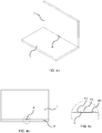
- FIG. 1 illustrates the element 1 comprising a dismantling groove 4 as well as the insertion groove 2 in one and the same element 1.
- the insertion groove 2 extends along the element 1 and from a first side 5 towards a second side 6 of the element 1. Also, the insertion groove 2 may extend along an edge of the element, and be located a distance from the edge.
- the dismantling groove 4 extends from the first side 5 to the insertion groove 2.
- the dismantling groove 4 is configured to receive a dismantling tool (not shown) for pushing the tongue away from the tongue groove 3. Since the insertion groove 2 and the dismantling groove 4 are provided in the same element, the production process may be simplified, making it more efficient to produce, and may be thus more cost efficient.
- the panel is particularly suited to be produced in existing production equipment where elements are produced with an insertion groove 2, but in which a separate tool for providing the dismantling groove 4 cannot be added, or added with significant difficulty.
- the insertion groove 2 and the dismantling groove 4 may in some embodiments be provided using separate tools, which may be still more efficient than providing the insertion groove and the dismantling groove in separate elements.
- FIG. 1 illustrates an embodiment of the element 1 arranged for assembly using a locking device for locking the element 1 to an adjacent element 7.
- the element 1 and the adjacent element 7 may be boards or panels of a furniture product that are connected perpendicular to each other, i.e., with a main surface of the element 1 perpendicular to a main surface of the adjacent element 7.
- An edge section 8 of the adjacent element 7 is arranged in an edge section groove 9 of the element 1 for locking the adjacent element 7 and the element 1 together in a first direction.
- a locking device in the form of a flexible tongue may be arranged in the insertion groove 2 in the edge section groove 9 and extend into a tongue groove 3 at the edge section 8.
- the tongue groove 3 and a tip of the tongue extending into the tongue groove 3 may have complementary shapes.
- the flexible tongue and the tongue groove 3 cooperate for locking the element 1 and the adjacent element 7 together in a second direction, which is essentially perpendicular to the first direction.
- the flexible tongue is, during assembly of the element 1 and the adjacent element 7, pushed into the insertion groove 2 when the edge section 8 is inserted into the edge section groove 9.
- the flexible tongue springs back and into the tongue groove 3 when the element 1 and the adjacent element 7 have reached a connected state.
- FIGS. 2-3 illustrate embodiments of a method for providing the dismantling groove 4 in the element 1.
- the element 1 may be panel-shaped having a first side 5 and an opposing second side 6.
- Various other grooves and/or profiles may already be present in the element 1, such as the edge section groove 9.
- the insertion groove 2 and the dismantling groove 4 may be provided using a milling tool.
- the element 1 may be passed through a production line wherein a number of milling tools are present in order to provide various grooves, recesses and profiles along the element 1.
- the insertion groove 2 is provided in the element 1 such that it extends along the element 1, for example along an edge of the element 1, and between the first side 5 and the second side 6. Also, the insertion groove 2 is configured for receiving a flexible tongue of a locking arrangement for locking the element 1 to the adjacent element 7 having the tongue groove 3.
- the insertion groove 2 may be provided to extend at a non-perpendicular angle relative the first side 5, such that the tongue is arranged non-perpendicularly relative the adjacent element 7.
- the insertion groove 2 may be provided to extend at an angle of 20° to 70°, for example, 30 to 45°.
- the dismantling groove 4 is provided in the same element 1 as the insertion groove 2 and such that it extends from the first side 5 to the insertion groove 2. Hence, access to the insertion groove 2, and thus to a tongue when arranged therein, is provided from the first side 5 of the element 1.
- the dismantling groove 4 is configured to receive a dismantling tool (not shown) for dismantling the element 1 from the adjacent element 7.
- a dismantling groove 4 may extend along a portion of the insertion groove 2.
- a dismantling groove 4 may be 2 to 20% of the length of the insertion groove, for example, 5 to 10% of the length of the insertion groove.
- Multiple tongues may be arranged spaced apart in the insertion groove 2. Each tongue may, e.g., be about 20-400 mm long. If multiple tongues are provided in the same element 1, the tongues may be spaced apart, e.g., 0,5-1 times the length of the tongue. The distance between two tongues depends on the required strength of the locking arrangement. No distance or a shorter distance, such as about 1 mm to about 5 mm, between two tongues provides a stronger locking arrangement.
- the dismantling groove 4 may be provided to coincide with the location between the locations for two tongues. Hence, the dismantling groove 4 may be about 20-80 mm long, or about the same length as, or shorter than, the distance between two tongues. This provides for inserting a dismantling tool through the dismantling groove 4, and pushing the dismantling tool along the insertion groove 2. If the dismantling groove is provided on a top surface of the element 1 and visible during use of the element 1, the dismantling groove 4 may be about 20-50 mm long. If the dismantling groove is provided on a bottom surface of the element 1 and non-visible during use of the element 1, the dismantling groove 4 may be about 20-80 mm long.
- different elements may have different lengths of the dismantling groove 4 in order to optimize strength and at the same time reduce the impact on surfaces that are used. For example, reducing the length on visible surfaces reduces the risk of dust and particle agglomeration in such surfaces.
- the dismantling tool may e.g. be rod-shaped with a cross-sectional shape that substantially corresponds to a portion of the cross-sectional shape of the insertion groove 2.
- a tip of the dismantling tool may be pointed, such that the tongue is pushed into the insertion groove 2 and away from the tongue groove 3 when the dismantling tool is positioned between the tongue and the tongue groove 3.
- the dismantling groove 4 is sufficiently wide to receive the dismantling tool, and may be about 1-3 mm, preferably about 2 mm.
- the dismantling groove 4 measured from the edge section groove 9 parallel with the first side 5 has a first width.
- the insertion groove 2 measured from the edge section groove 9 parallel with the first side 5 has a second width, which is larger than the first width.
- insertion groove 2 may be configured for a flexible tongue that may be received between the dismantling tool and a bottom wall 10 ( FIG. 1 ) of the insertion groove 2 when the dismantling tool is received in the insertion groove 2.
- FIG. 1 shows a cross-section of element 1, wherein, at the location of the dismantling groove 4, the bottom of the insertion groove 2 is extended to a second depth into the element 1, providing a deeper bottom wall 15 in a portion of the insertion groove 2 which coincides with the dismantling groove 4.
- the insertion groove 2 and the dismantling groove 4 are provided by milling with a single milling tool 20, such as illustrated in the embodiment of FIG. 3 .
- the milling tool 20 has a first cutting surface 21 for milling the insertion groove 2 and a second cutting surface 22 for milling the dismantling groove 4.
- the insertion groove 2 is milled with the milling tool 20 in a first position, such as the position illustrated in FIGS. 2-3 .
- the dismantling groove 4 is milled by moving the milling tool in a radial direction relative its longitudinal axis to a second position while the element 1 and/or the tool is moving along the element 1. When the length of the dismantling groove 4 has been provided, the milling tool 20 is returned to the first position.
- the insertion groove 2 as well as the dismantling groove 4 is generated simultaneously while the milling tool 20 is in the second position.
- This provides for increased efficiency for producing the element 1.
- It also provides for high production tolerances between the insertion groove 2 and the dismantling groove 4, which will be provided with a fixed relationship. This in turn leads to a stable assembled product.
- milling tool 20 may be controlled to mill, e.g. by CNC milling, the insertion groove 2 and the dismantling groove 4 in a continuous milling action, such as while the element 1 is passed along a production line.
- the insertion groove 2 is provided with a first depth into the element 1 along the insertion groove 2.
- the depth of the insertion groove 2 is extended to a second depth into the element 1, which is deeper than the first depth.
- the difference between the second depth and first depth may be correlated to the width of the insertion groove 2.
- the insertion groove 2 and the dismantling groove 4 may be provided with a single tool in a continuous, or substantially continuous, action.
- the dismantling groove 4 is provided with a guide surface 11 extending from the first side 5 of the element 1 towards the second side 6 of the element 1 and along the insertion groove 2.
- the guide surface may be angled at less than 90 degrees relative the first side 5 of the element 1.
- the guide surface may be angled 45 to 85 degrees, for example, 60 to 80 degrees, relative to the first side 5 of the element 1.
- the dismantling groove 4 has an opening at the first side 5 of the element 1 that is wider than further down in the dismantling groove 4 towards the insertion groove 2, which forms the guide surface. This provides for guiding the dismantling tool towards the insertion groove 2.
- the guide surface is straight.
- the guide surface 11 is curved between first side 5 and the insertion groove 2. This forms a narrowed portion of the dismantling groove. This further facilitates guiding the dismantling tool to a correct position in the insertion groove 2 without jamming the tool when it is positioned below the narrowed portion for pushing the tongue into the insertion groove 2.
- the guide surface may initially be angled less than 90 degrees relative the first side 5 at the first side, and have a gradually increased width from a narrowed section and towards the insertion groove 2 such that it is angled more than 90 degrees relative the first side 5 when it reaches the insertion groove 2.
- Such a curved guide surface may be provided with the second cutting surface 22 of the tool 20 having a curved shape.
- the method embodiments described above may be used to produce the element 1, such as in wood, composite wood, laminate, plastic etc.
- the element may be a panel, comprising a wood based material, such as a MDF or HDF panel, a particleboard or a plywood board.
- the panel may be covered by a decorative layer.
- the element 1 may also be produced using other production techniques, such as extrusion, wherein milling is not required.
- Such an element 1 comprises the first side 5 and the opposing second side 6.
- the insertion groove 2 extends along the element 1 and between the first side 5 and the second side 6.
- the insertion groove 2 may extend at a non-perpendicular angle relative the first side 5.
- the insertion groove 2 is configured for receiving a flexible tongue of a locking arrangement for locking the element 1 to another element, such as adjacent element 7.
- the dismantling groove 4 extends from the first side 5 to the insertion groove 2 and along a portion of the insertion groove 2.
- the dismantling groove 4 is configured to receive a dismantling tool for dismantling the element 1 from the other element.
- the dismantling groove 4 may be open towards the edge section groove 9 of the element 1.
- the dismantling groove 4 may have one or several walls 4a, 4b, 4c ( Fig. 4c ) extending from the first side 5 of the element 1 to the insertion groove 2, and from one end of the dismantling groove 4 to the other end of the dismantling groove 4 along the insertion groove 2.
- the dismantling groove 4 may have a substantially U-shaped cross section taken parallel to the first side 5.
- the adjacent panel 7 When the adjacent panel 7 is positioned in the edge section groove 9, it is supported by an upper side surface 12 of the edge section groove 9, which may be substantially perpendicular to the first side 5, at the positions where only the insertion groove 2 is located, i.e., where the dismantling groove 4 is not located. It is also supported by a lower side surface 13 of the edge section groove 9, which is parallel with the upper side surface 12. At the location of the dismantling groove 4, the adjacent panel 7 is only supported by the lower side surface 13. This provides for sufficient stability of the adjacent panel 7 and yet an efficient production of the element 1 with the insertion groove 2 and the dismantling groove 4.
- FIGS. 4a-4c illustrates the element 1 connected to the adjacent panel 7.
- a single dismantling groove 4 is provided in the element 1, and between two insertion grooves (not illustrated). Multiple dismantling grooves 4 may be provided as described above.
- the dismantling groove 4 extends along the element 1.
- the dismantling groove 4 is open towards the adjacent element 7.
- the edge of the dismantling groove 4 at the first side 5 of the element 1 may be partly curved, such as with a curved section at each end of the dismantling groove 4 and a substantially straight section therebetween.
- the element 1 and the other element 7 may be arranged such that the first side 5 with the dismantling groove 4 is facing upwards as in the illustrated in the FIGS.
- the panels may be arranged in any way e.g. such that the first side 5 with the dismantling groove 4 is facing downwards.
- a dismantling groove facing downward may have the advantage that the dismantling groove is less visible and/or that less particles, such as dust, are accumulated in the insertion groove.
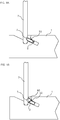
- FIG. 5a shows in a cross-sectional view an embodiment of the element 1 and the other element 2 in a connected state.
- the flexible tongue 50 cooperates with the tongue groove 3 for locking the adjacent element 7 and the element 1 together in the second direction.
- FIG. 5b is a cross-sectional view an embodiment of the element 1 and other element 7 during an insertion of the dismantling tool 60 into the dismantling groove and the insertion groove 2.
Landscapes
- Engineering & Computer Science (AREA)
- Mechanical Engineering (AREA)
- General Engineering & Computer Science (AREA)
- Life Sciences & Earth Sciences (AREA)
- Wood Science & Technology (AREA)
- Forests & Forestry (AREA)
- Connection Of Plates (AREA)
- Milling Processes (AREA)
- Milling, Drilling, And Turning Of Wood (AREA)
- Furniture Connections (AREA)
- Snaps, Bayonet Connections, Set Pins, And Snap Rings (AREA)
Claims (14)
- Procédé de fourniture d'une rainure de démontage (4) dans un élément (1) pour un produit destiné à être assemblé par plusieurs éléments verrouillés par un dispositif de verrouillage incluant une languette flexible (50), comprenant :la fourniture d'un élément (1) présentant un premier côté (5) et un second côté opposé (6) ;la fourniture d'une rainure d'insertion (2) dans l'élément (1) qui s'étend le long de l'élément (1) entre le premier côté (5) et le second côté (6) et qui est configurée pour recevoir une languette flexible (50) d'un dispositif de verrouillage pour verrouiller l'élément (1) à un autre élément (7) présentant une rainure de languette (3) ;la fourniture d'une rainure de démontage (4) dans l'élément (1) qui s'étend à partir du premier côté (5) jusqu'à la rainure d'insertion (2) et le long d'une portion de la rainure d'insertion (2), et étant configurée pour recevoir un outil de démontage (60) pour démonter l'élément (1) de l'autre élément (7),caractérisé parla fourniture de la rainure d'insertion (2) et la rainure de démontage (4) par fraisage avec un seul outil de fraisage (20) présentant une première surface de coupe (21) pour fraiser la rainure d'insertion (2) et une seconde surface de coupe (22) pour fraiser la rainure de démontage (4), etle fraisage de la rainure d'insertion (2) avec l'outil de fraisage (20) dans une première position et la rainure de démontage (4) en déplaçant l'outil de fraisage (20) dans une direction radiale par rapport à son axe longitudinal jusqu'à une seconde position.
- Procédé selon l'une quelconque des revendications précédentes, comprenant la fourniture de la rainure d'insertion (2) avec au moins une première profondeur dans l'élément (1) le long de la rainure d'insertion entière (2), et la fourniture de la rainure d'insertion (2) avec une seconde profondeur dans l'élément (1) à l'endroit de la rainure de démontage (4) et de sorte que la seconde profondeur est plus profonde que la première profondeur.
- Procédé selon l'une quelconque des revendications précédentes, dans lequel la fourniture de la rainure de démontage (4) comprend la fourniture d'une surface de guide (11) s'étendant à partir du premier côté (5) vers le second côté (6) et étant inclinée au moins partiellement à moins de 90 degrés par rapport au premier côté (5).
- Procédé selon l'une quelconque des revendications précédentes, comprenant le contrôle d'un seul outil de fraisage (20) pour fraiser la rainure d'insertion (2) et la rainure de démontage (4) dans une action de fraisage continue.
- Procédé selon l'une quelconque des revendications précédentes, dans lequel le premier côté (5) comprend une rainure de section de bord (9) et l'autre élément (7) comprend une section de bord (8), dans lequel la section de bord (8) est configurée pour coopérer avec la rainure de section de bord (9) pour verrouiller l'autre élément (7) et l'élément (1) ensemble dans une première direction.
- Procédé selon la revendication 5, dans lequel la rainure de section de bord (9) comprend la rainure d'insertion (2).
- Procédé selon la revendication 5 ou 6, dans lequel la section de bord (8) comprend la rainure de languette (3), dans lequel la languette flexible (50) est configurée pour coopérer avec la rainure de languette (3) pour verrouiller l'autre élément (7) et l'élément (1) ensemble dans une seconde direction, qui est perpendiculaire à la première direction.
- Elément (1) pour un produit destiné à être assemblé par plusieurs éléments verrouillés par un dispositif de verrouillage incluant une languette flexible (50), comprenant
un premier côté (5) et un second côté opposé (6) ;
une rainure d'insertion (2) s'étendant le long de l'élément (1) et entre le premier côté (5) et le second côté (6), et étant configurée pour recevoir une languette flexible (50) d'un dispositif de verrouillage pour verrouiller l'élément (1) à un autre élément (7) ;
une rainure de démontage (4) s'étendant à partir du premier côté (5) jusqu'à la rainure d'insertion (2) et le long d'une portion de la rainure d'insertion (2), et étant configurée pour recevoir un outil de démontage (60) pour démonter l'élément (1) de l'autre élément (7) ; et
caractérisé en ce que
la profondeur de la rainure d'insertion (2) est étendue à l'endroit de la rainure de démontage (4). - Elément selon la revendication 8, dans lequel une surface de guide (11) de la rainure de démontage (4), qui s'étend à partir du premier côté (5) vers la rainure d'insertion (2), est inclinée au moins partiellement à moins de 90 degrés par rapport au premier côté (5).
- Elément selon l'une quelconque des revendications 8 ou 9, dans lequel le premier côté (5) comprend une rainure de section de bord (9) qui comprend la rainure d'insertion (2).
- Elément selon la revendication 10, dans lequel la rainure de section de bord (9) est configurée pour coopérer avec une section de bord (8) de l'autre élément pour verrouiller l'élément et l'autre élément ensemble dans une première direction.
- Elément selon l'une quelconque des revendications 8-11, dans lequel la languette flexible (50) est configurée pour coopérer avec une rainure de languette (3) à une section de bord de l'autre élément, pour verrouiller l'élément (1) et l'autre élément (7) ensemble dans une seconde direction, qui est de préférence perpendiculaire à la première direction.
- Elément selon l'une quelconque des revendications 8-12, dans lequel la languette flexible (50) est configurée pour être poussée dans la rainure d'insertion (2) lorsqu'une section de bord (8) de l'autre élément est insérée dans une rainure de section de bord (9) de l'élément (1) pendant l'assemblage de l'élément (1) et l'autre élément (7) et/ou pendant le démontage.
- Elément selon la revendication 13, dans lequel la languette flexible (50) est configurée pour revenir élastiquement et dans la rainure de languette (3) lorsque l'élément (1) et l'autre élément (7) ont atteint un état connecté.
Applications Claiming Priority (2)
| Application Number | Priority Date | Filing Date | Title |
|---|---|---|---|
| SE1650159 | 2016-02-09 | ||
| PCT/SE2017/050124 WO2017138874A1 (fr) | 2016-02-09 | 2017-02-09 | Élément et procédé de fourniture de rainure de démontage |
Publications (3)
| Publication Number | Publication Date |
|---|---|
| EP3414462A1 EP3414462A1 (fr) | 2018-12-19 |
| EP3414462A4 EP3414462A4 (fr) | 2019-08-28 |
| EP3414462B1 true EP3414462B1 (fr) | 2020-10-07 |
Family
ID=59496827
Family Applications (1)
| Application Number | Title | Priority Date | Filing Date |
|---|---|---|---|
| EP17750523.7A Not-in-force EP3414462B1 (fr) | 2016-02-09 | 2017-02-09 | Élément et procédé de fourniture de rainure de démontage |
Country Status (10)
| Country | Link |
|---|---|
| US (2) | US10486245B2 (fr) |
| EP (1) | EP3414462B1 (fr) |
| JP (1) | JP6903673B2 (fr) |
| KR (1) | KR20180110027A (fr) |
| CN (1) | CN108603523B (fr) |
| BR (1) | BR112018014034A2 (fr) |
| CA (1) | CA3011703A1 (fr) |
| MY (1) | MY190803A (fr) |
| RU (1) | RU2711865C1 (fr) |
| WO (1) | WO2017138874A1 (fr) |
Families Citing this family (45)
| Publication number | Priority date | Publication date | Assignee | Title |
|---|---|---|---|---|
| UA109938C2 (uk) | 2011-05-06 | 2015-10-26 | Механічна фіксуюча система для будівельних панелей | |
| US9726210B2 (en) | 2013-09-16 | 2017-08-08 | Valinge Innovation Ab | Assembled product and a method of assembling the product |
| EP3047160B1 (fr) | 2013-09-16 | 2019-01-09 | Välinge Innovation AB | Meuble |
| AU2014376416B2 (en) | 2014-01-10 | 2019-08-29 | Valinge Innovation Ab | A furniture panel |
| US9714672B2 (en) | 2014-01-10 | 2017-07-25 | Valinge Innovation Ab | Panels comprising a mechanical locking device and an assembled product comprising the panels |
| SG11201608909VA (en) | 2014-05-09 | 2016-11-29 | Vaelinge Innovation Ab | Mechanical locking system for building panels |
| RU2709003C2 (ru) | 2014-12-19 | 2019-12-12 | Велинге Инновейшн Аб | Панели, содержащие запирающее устройство, и собранное изделие, содержащее панели |
| US10670064B2 (en) | 2015-04-21 | 2020-06-02 | Valinge Innovation Ab | Panel with a slider |
| CA2983111A1 (fr) | 2015-04-30 | 2016-11-03 | Valinge Innovation Ab | Panneau a dispositif de fixation |
| CN108026956B (zh) | 2015-09-22 | 2020-07-17 | 瓦林格创新股份有限公司 | 包括机械锁定装置的镶板和包括所述镶板的组合产品 |
| EP3384165B1 (fr) | 2015-12-03 | 2021-08-04 | Välinge Innovation AB | Set de panneaux comprenant un dispositif de verrouillage mécanique |
| KR102746991B1 (ko) | 2016-01-26 | 2024-12-24 | 뵈린게 이노베이션 에이비이 | 기계식 잠금 디바이스를 포함하는 패널들 및 패널들을 포함하는 조립된 제품 |
| CN108496013B (zh) | 2016-02-04 | 2020-06-02 | 瓦林格创新股份有限公司 | 用于装配产品的一组镶板 |
| EP3413752B1 (fr) | 2016-02-09 | 2020-11-25 | Välinge Innovation AB | Ensemble de trois éléments en forme de panneau |
| MX2018009631A (es) | 2016-02-15 | 2018-12-17 | Vaelinge Innovation Ab | Un metodo para formar un panel para un producto de mobiliario. |
| PL3532737T3 (pl) | 2016-10-27 | 2024-09-30 | Välinge Innovation AB | Zestaw paneli z mechanicznym urządzeniem blokującym |
| CN110621889A (zh) | 2017-05-15 | 2019-12-27 | 瓦林格创新股份有限公司 | 用于组合产品的元件和锁定装置 |
| EP3728869B1 (fr) | 2017-12-22 | 2023-01-25 | Välinge Innovation AB | Ensemble de panneaux, leur procédé d'assemblage et dispositif de verrouillage pour un produit de mobilier |
| DK3728870T3 (da) | 2017-12-22 | 2023-07-24 | Vaelinge Innovation Ab | Pladesæt |
| MY204146A (en) | 2018-03-23 | 2024-08-09 | Vlinge Innovation Ab | Panels comprising a mechanical locking device and an assembled product comprising the panels |
| EP3781824B1 (fr) | 2018-04-18 | 2024-04-10 | Välinge Innovation AB | Ensemble de panneaux avec un dispositif de verrouillage mécanique |
| CN112262265B (zh) | 2018-04-18 | 2022-12-20 | 瓦林格创新股份有限公司 | 对称榫舌和t形交叉组件 |
| JP7305673B2 (ja) * | 2018-04-18 | 2023-07-10 | ベーリンゲ、イノベイション、アクチボラグ | 機械的ロック装置を有するパネルのセット |
| CN112119226B (zh) | 2018-04-18 | 2022-05-27 | 瓦林格创新股份有限公司 | 具有机械锁定装置的镶板组 |
| US11614114B2 (en) | 2018-04-19 | 2023-03-28 | Valinge Innovation Ab | Panels for an assembled product |
| PE20210692A1 (es) | 2018-08-30 | 2021-04-12 | Valinge Innovation Ab | Conjunto de paneles con un dispositivo de bloqueo mecanico |
| PT3844407T (pt) | 2018-08-30 | 2024-06-18 | Vaelinge Innovation Ab | Conjunto de painéis com dispositivo de travamento mecânico |
| WO2020156954A1 (fr) | 2019-01-29 | 2020-08-06 | Vilox Ab | Système d'assemblage pour des parties de meuble |
| EP3730807A1 (fr) | 2019-04-26 | 2020-10-28 | Välinge Innovation AB | Ensemble de panneaux avec un dispositif de verrouillage mecanique |
| SE545364C2 (sv) * | 2019-09-26 | 2023-07-18 | Alvar Lundgren | Beslag för fixering av skåprygg |
| EP3834661A1 (fr) | 2019-12-11 | 2021-06-16 | Välinge Innovation AB | Système de verrouillage mécanique pour panneaux |
| WO2021126070A1 (fr) * | 2019-12-19 | 2021-06-24 | Välinge Innovation AB | Ensemble de panneaux dotés d'un dispositif de verrouillage mécanique |
| US11828311B2 (en) | 2020-01-22 | 2023-11-28 | Valinge Innovation Ab | Set of panels with a mechanical locking device |
| EP3871560A1 (fr) | 2020-02-26 | 2021-09-01 | Välinge Innovation AB | Ensemble de panneaux comportant un dispositif de verrouillage mécanique |
| EP3871559A1 (fr) | 2020-02-26 | 2021-09-01 | Välinge Innovation AB | Ensemble de panneaux comportant un dispositif de verrouillage mécanique |
| US11702844B2 (en) | 2020-06-05 | 2023-07-18 | Valinge Innovation Ab | Building panels comprising a locking device |
| CN115867171B (zh) * | 2020-07-17 | 2025-12-23 | 瓦林格创新股份有限公司 | 用于镶板的机械锁定系统 |
| WO2022124974A1 (fr) | 2020-12-11 | 2022-06-16 | Välinge Innovation AB | Rail pour armoires |
| CN116685244A (zh) * | 2021-01-07 | 2023-09-01 | 瓦林格创新股份有限公司 | 楔形榫舌插槽 |
| CA3207233A1 (fr) | 2021-01-19 | 2022-07-28 | Valinge Innovation Ab | Ensemble de panneaux, son procede d'assemblage et dispositif de verrouillage pour un produit de mobilier |
| CN116888333A (zh) | 2021-02-03 | 2023-10-13 | 瓦林格创新股份有限公司 | 包括锁定装置的建筑镶板 |
| EP4288672A4 (fr) | 2021-02-08 | 2024-12-25 | Välinge Innovation AB | Ensemble ferrure de meuble, support de montage et procédé d'assemblage de meuble |
| US12018707B2 (en) | 2021-03-01 | 2024-06-25 | Välinge Innovation AB | Mechanical connection arrangement for panels |
| US12345283B2 (en) | 2021-06-11 | 2025-07-01 | Välinge Innovation AB | Static load compression spring |
| US12279735B2 (en) | 2022-03-04 | 2025-04-22 | Haier Us Appliance Solutions, Inc. | Pocket handle assembly for an appliance |
Family Cites Families (261)
| Publication number | Priority date | Publication date | Assignee | Title |
|---|---|---|---|---|
| US291032A (en) | 1884-01-01 | Isaac g- | ||
| US634581A (en) | 1898-11-21 | 1899-10-10 | Robert H Miller | Carpenter's square. |
| US701000A (en) | 1901-07-31 | 1902-05-27 | Carl F W Ahrens | File-cabinet. |
| US861911A (en) | 1905-11-04 | 1907-07-30 | William Stewart | Joint for articles of furniture or woodwork. |
| US881673A (en) | 1907-03-11 | 1908-03-10 | Arthur L Ellison | Wardrobe or safe. |
| US1534468A (en) | 1922-10-30 | 1925-04-21 | Jr John J Shea | Joint structure |
| US1533099A (en) | 1924-07-14 | 1925-04-14 | Robert E Carroll | Square-corner glue joint |
| US1800386A (en) | 1926-08-28 | 1931-04-14 | Andrew Hoffman Mfg Company | Display rail |
| US1800387A (en) | 1926-12-30 | 1931-04-14 | Andrew Hoffman Mfg Company | Article-supporting device |
| US1802245A (en) | 1930-08-26 | 1931-04-21 | Clarence L Foretich | Display stand and shelving |
| US1954242A (en) | 1932-07-28 | 1934-04-10 | Thomas E Heppenstall | Dovetail spring joint |
| US2360451A (en) | 1942-06-02 | 1944-10-17 | Stone Abraham | Collapsible clothing container |
| US2362904A (en) | 1943-01-20 | 1944-11-14 | Allied Purchasing Corp | Joint for demountable furniture |
| US2496184A (en) | 1946-06-11 | 1950-01-31 | Canon Paul L Von | Furniture drawer construction and method |
| CH365507A (de) | 1958-11-17 | 1962-11-15 | Antonius Bus Johannes | Einrichtung zur Verbindung von senkrecht aufeinanderstehenden Wänden mit selbsttätiger Sperrung, insbesondere Möbelwänden |
| US3002630A (en) | 1960-05-24 | 1961-10-03 | Robert E Heisser | Toothbrush rack |
| US3195968A (en) | 1962-12-06 | 1965-07-20 | Lok Trim Corp | Knock-down furniture |
| DE1240638B (de) | 1963-03-07 | 1967-05-18 | Kueche | Zerlegbares Moebelstueck |
| AT260460B (de) | 1963-08-19 | 1968-03-11 | Trepatent As | Führung für Schubladen, Regalplatten od. dgl. |
| US3245694A (en) * | 1964-08-24 | 1966-04-12 | James E Parker | Removable ball retainer block |
| US3313054A (en) | 1965-06-09 | 1967-04-11 | Poster Products Inc | Display devices |
| IS831B6 (is) | 1965-10-28 | 1973-04-12 | Nordischer Maschinenbau Rud. BaaderNordischer Maschinenbau, Rud. Baader | Aðferð til þess að fjarlægja lifur úr fiskiTæki til að hausa hásskorinn fisk, þannig að vætubeinið verði eftir á fiskinum |
| US3410441A (en) | 1966-06-29 | 1968-11-12 | Jeff S. Rhyne | Container |
| US3347610A (en) | 1966-07-28 | 1967-10-17 | Pilliod Cabinet Company | Cabinet construction |
| DE1955922C3 (de) | 1969-11-06 | 1974-01-10 | Hefendehl, Hansfriedrich, 5893 Kierspe | Kastenmöbel aus Kunststoff |
| US3722704A (en) | 1970-07-23 | 1973-03-27 | Castelli Sas Anonima | Structural components for the composition of disassemblable pieces offurniture |
| US3765465A (en) | 1972-01-05 | 1973-10-16 | Deutsch Fastener Corp | Retractable captive fastener |
| GB1398187A (en) | 1972-06-22 | 1975-06-18 | Schreiber Furniture | Kitchen cabinets |
| US3884002A (en) | 1973-03-15 | 1975-05-20 | American Store Equip | Partition system |
| US3885845A (en) | 1974-06-27 | 1975-05-27 | Hans Krieks | Knock-down furniture system |
| US3981118A (en) | 1974-10-17 | 1976-09-21 | The Goodyear Tire & Rubber Company | Clamping insert |
| CA1062321A (fr) | 1976-05-12 | 1979-09-11 | I. T. W. Ltd. | Rondelles pour raccords de meubles |
| DE2635237A1 (de) | 1976-08-05 | 1978-02-09 | Heinze Fa R | Moebelscharnier |
| US4116510A (en) | 1977-03-03 | 1978-09-26 | Gte Automatic Electric Laboratories Incorporated | Chassis formed of sheet stock |
| US4099887A (en) | 1977-07-18 | 1978-07-11 | Einhard Mackenroth | Structural joints |
| US4222544A (en) | 1977-08-10 | 1980-09-16 | Kenneth Crowder | Picture rail apparatus |
| SE409603B (sv) | 1977-12-20 | 1979-08-27 | Stockum Design Ab | Forbindning |
| SE7809081L (sv) | 1978-08-29 | 1980-03-01 | Hafa Fabriks Ab | Anordning for uppberning av skap, speglar, hyllor och andra detaljer |
| US4211379A (en) | 1978-11-20 | 1980-07-08 | Morgan Myron B | Panelboard and mounting fixture combination |
| US4299067A (en) | 1979-10-30 | 1981-11-10 | J. C. Penney Company, Inc. | Partition connector system |
| US4308961A (en) | 1980-05-05 | 1982-01-05 | Kunce Thomas M | Article supporting structure |
| US4324517A (en) | 1980-06-16 | 1982-04-13 | Sps Technologies, Inc. | Panel fastener assembly with retainer ring |
| US4332179A (en) * | 1980-10-08 | 1982-06-01 | Wallis Bernard J | Combined punch retainer and fluid-actuated stripper |
| DE3047642A1 (de) * | 1980-12-17 | 1982-10-28 | Arturo Salice S.p.A., 22060 Novedrate, Como | Verbindungsbeschlag |
| DE3103281C2 (de) | 1981-01-31 | 1984-05-10 | C + A Dick GmbH, 5275 Bergneustadt | Materialschrank |
| US4377100A (en) * | 1981-02-19 | 1983-03-22 | Wallis Bernard J | Punch retainer |
| FR2501805A1 (fr) | 1981-03-10 | 1982-09-17 | Haeusler Roland | Nouveau systeme d'assemblage du genre a tenon et mortaise et articles mobiliers incorporant ledit systeme |
| FR2517187A1 (fr) | 1981-12-01 | 1983-06-03 | Beaux Dominique | Caisson demontable a usage de meuble |
| US4509648A (en) | 1982-07-26 | 1985-04-09 | The Stanley Works | Merchandising display system and components therefor |
| US4593734A (en) * | 1983-09-26 | 1986-06-10 | M. Bosley Wright | Frame routing apparatus |
| US4629076A (en) | 1984-05-10 | 1986-12-16 | Amstore Corporation | Slatboard |
| US4595105A (en) | 1984-09-12 | 1986-06-17 | Gold Kenneth S | Interlocking bookrack |
| US4558620A (en) * | 1984-10-05 | 1985-12-17 | Wallis Bernard J | Punch retainer |
| US4750794A (en) | 1984-11-21 | 1988-06-14 | Bass Cabinet Manufacturing, Inc. | Slide-fitted article of furniture |
| US4597122A (en) | 1985-06-10 | 1986-07-01 | Hirsh Company | Free-standing drawer |
| US4615448A (en) | 1985-09-27 | 1986-10-07 | Masonite Corporation | Display panel |
| US4891897A (en) | 1985-12-12 | 1990-01-09 | Gieske Detlef J | Display panel |
| FR2597173B1 (fr) | 1986-04-10 | 1988-10-07 | Forschle Andre | Dispositif pour assembler et modifier facilement la composition d'un meuble en kit |
| GB8612597D0 (en) | 1986-05-23 | 1986-07-02 | George W R | Joint between members |
| FR2602013B1 (fr) | 1986-07-25 | 1988-12-30 | Kapikian Jean Claude | Systeme d'assemblage du type a tenon et mortaise aisement montable et demontable |
| US4815908A (en) | 1986-10-14 | 1989-03-28 | Avibank Mfg., Inc. | Captive panel fastener assembly |
| US4726270A (en) * | 1987-01-05 | 1988-02-23 | Lucas Rose E | Stamping system |
| US4844266A (en) | 1987-07-16 | 1989-07-04 | Intercraft Industries Corporation | Display system |
| CA1297934C (fr) | 1987-07-24 | 1992-03-24 | Craig Mengel | Methode de jointoiement de pieces substantiellement rigides et dispositifs connexe |
| US4886326A (en) | 1988-01-29 | 1989-12-12 | Tetrad Marketing/Sales Ltd. | Interlock system for ready to assemble furniture, and furniture incorporating such system |
| US4961295A (en) | 1988-03-14 | 1990-10-09 | Kosch Sr Paul | Metal slat and wall system utilizing same |
| US4817900A (en) | 1988-05-09 | 1989-04-04 | Gorrie Advertising Management Limited | Support device for use on a display wall |
| IT215989Z2 (it) | 1988-09-02 | 1991-03-26 | Cattarozzi Andrea | Contenitore modulare componibile e trasportabile manualmente, per la conservazione di sostanze, in special modo per uso alimentare |
| NL8802459A (nl) | 1988-10-07 | 1990-05-01 | Homburg Interieuren B V | Uitstalwand. |
| US4944416A (en) | 1988-11-21 | 1990-07-31 | Petersen Robert J | Light-weight slot-wall display panel |
| US5471804A (en) | 1988-11-21 | 1995-12-05 | Winter, Iv; Amos G. | Building system using prefabricated building panels and fastening components used therewith |
| US4909581A (en) | 1988-12-12 | 1990-03-20 | American Moulding & Millwork Company | Drawer construction |
| WO1990007066A2 (fr) * | 1988-12-13 | 1990-06-28 | Rudolf Tanner | Attache pour relier par liaison de forme |
| US5018323A (en) | 1989-05-12 | 1991-05-28 | Knud Clausen | Wall panel system |
| US5109993A (en) | 1989-10-31 | 1992-05-05 | Hutchison V James | Merchandise display system and merchandise holder therefor |
| US5138803A (en) | 1991-01-11 | 1992-08-18 | Commercial And Architectural Products, Inc. | Display panel assembly |
| US5121578A (en) | 1991-01-28 | 1992-06-16 | Holz Plastics, Inc. | Slat wall decorating system |
| US5209556A (en) | 1991-04-01 | 1993-05-11 | Anderson Robert F | Drawer assembly |
| GB2269839B (en) | 1991-04-01 | 1995-06-07 | Walter Lindal | Wooden frame building construction |
| US5114265A (en) | 1991-04-15 | 1992-05-19 | Grisley Kenneth M | Interlocking routed joint |
| US5125518A (en) | 1991-08-12 | 1992-06-30 | Innovative Accessories | Interlocking hanging system |
| US5212925A (en) | 1991-11-21 | 1993-05-25 | Mcclinton John | Wall corner composite, mold and method for producing glazed unit for such |
| US5360121A (en) | 1992-08-07 | 1994-11-01 | Commerical And Architectural Products, Inc. | Slotted display wall panel |
| CH685276A5 (de) | 1992-11-25 | 1995-05-31 | Werner Schmidt | Bausatz zur Herstellung von Regalen, Schränken und Wohnwänden und Regale, Schränke und Wohnwände hergestellt mit diesem Bausatz. |
| ZA94676B (en) * | 1993-02-03 | 1994-08-03 | Rohm & Haas | Reduction of microfoam in spray-applied waterborne composition. |
| US5423155A (en) | 1993-06-02 | 1995-06-13 | Darko Company, Inc. | Panel for resurfacing slat walls |
| US5499667A (en) * | 1994-06-21 | 1996-03-19 | Nakanishi Construction Company | Drill/cutting bit, and method of making structural joint |
| US5527103A (en) | 1993-10-01 | 1996-06-18 | Pittman; Charles | Cabinet of improved design and construction |
| US5375802A (en) | 1993-11-17 | 1994-12-27 | Bill Branham Designs, Ltd. | Structure for fastening facing structural units |
| US5451102A (en) | 1994-01-13 | 1995-09-19 | Chuan; Yuan-Jung | Cabinet with connecting mechanism for two adjacent wall plate |
| US5499886A (en) | 1994-03-02 | 1996-03-19 | Sauder Woodworking Co. | Coupling assembly for furniture components |
| DE4410901A1 (de) | 1994-03-29 | 1995-10-05 | Licentia Gmbh | Kühlschrank mit Kühlgutablagen |
| US5507331A (en) * | 1994-06-21 | 1996-04-16 | Nakanishi Construction Company | Drilling/cutting bit, and method of making joint |
| US5658086A (en) | 1995-11-24 | 1997-08-19 | Brokaw; Paul E. | Furniture connector |
| US5775521A (en) | 1996-03-22 | 1998-07-07 | Custom Plastics, Inc. | Office organizer |
| JPH09303345A (ja) * | 1996-05-15 | 1997-11-25 | Fuontaajiyu:Kk | 部材の連結方法、連結構造、および連結具 |
| CA2207533A1 (fr) | 1996-06-12 | 1997-12-12 | David P. Thurston | Systdme d'accrochage reglable |
| US5950389A (en) | 1996-07-02 | 1999-09-14 | Porter; William H. | Splines for joining panels |
| US5810505A (en) | 1996-07-26 | 1998-09-22 | Kimball International, Inc. | Double threaded fastener system |
| US5711115A (en) | 1996-10-30 | 1998-01-27 | Design Components, Inc. | Fireplace shelf and mantel support system |
| US6050426A (en) | 1997-03-19 | 2000-04-18 | Leurdijk; Jan B. | Storage track system |
| US5857304A (en) | 1997-04-07 | 1999-01-12 | Abex Display Systems | Slidable locking system for disengageable panels |
| CA2204301C (fr) | 1997-05-02 | 2000-04-18 | Shang-Ming Lee | Systeme de raccords pour planches horizontales et planches verticales d'un meuble de rangement |
| NO974666L (no) | 1997-10-09 | 1999-04-12 | New Ideas | Sammenf°yningsanordning for plateformete konstruksjonsdeler, samt m°belkonstruksjon |
| AT406181B (de) | 1998-02-09 | 2000-03-27 | Blum Gmbh Julius | Befestigungsvorrichtung für die befestigung mehrerer möbelbeschläge an einem möbelteil |
| US6363645B1 (en) | 1998-02-25 | 2002-04-02 | Bruce A Hunter | Insert for display panels |
| US6059531A (en) * | 1998-06-19 | 2000-05-09 | Tai; Jen-Lung David | Impeller and fan blade attachment assembly |
| US5944294A (en) | 1998-07-06 | 1999-08-31 | Baer; Thomas C. | Mounting device in form of C-clamp mounted space from a wall |
| DE29820031U1 (de) | 1998-11-10 | 1999-02-25 | Grant, Alasdair E., 33659 Bielefeld | Formschlüsselige Verbindungseinrichtung für Möbel bzw. Plattenelemente |
| US6547086B1 (en) | 1999-03-25 | 2003-04-15 | Russell-William, Ltd. | Display wall panel |
| SE517478C2 (sv) | 1999-04-30 | 2002-06-11 | Valinge Aluminium Ab | Låssystem för mekanisk hofogning av golvskivor, golvskiva försedd med låssystemet samt metod för framställning av mekaniskt hopfogningsbara golvskivor |
| IT1307424B1 (it) | 1999-04-29 | 2001-11-06 | Costa S P A A | Metodo per la profilatura di listelli per parquet e macchinasquadratrice atta a realizzare tale metodo. |
| ES2228133T3 (es) | 1999-06-30 | 2005-04-01 | Akzenta Paneele + Profile Gmbh | Panel, asi como sistema de fijacion para paneles. |
| DE29911462U1 (de) | 1999-07-02 | 1999-11-18 | Akzenta Paneele & Profile Gmbh | Befestigungssystem für Paneele |
| DE10001076C1 (de) | 2000-01-13 | 2001-10-04 | Huelsta Werke Huels Kg | Paneelelement |
| SE517183C2 (sv) | 2000-01-24 | 2002-04-23 | Valinge Aluminium Ab | Låssystem för mekanisk hopfogning av golvskivor, golvskiva försedd med låssystemet och metod för framställning av sådana golvskivor |
| CA2404021A1 (fr) | 2000-03-24 | 2001-10-04 | Commercial And Architectural Products, Inc. | Systeme presentoir de marchandises |
| US6413007B1 (en) | 2000-05-01 | 2002-07-02 | Sauder Woodworking Co. | Joint assembly |
| DE60221788T2 (de) | 2001-01-12 | 2008-06-05 | Välinge Aluminium AB | Fussbodensystem umfassend mehrere mechanisch verbindbaren Fussbodenplatten |
| US6675979B2 (en) | 2001-05-21 | 2004-01-13 | Gregory Albert Taylor | Furniture assembly system |
| DE10138285A1 (de) | 2001-08-10 | 2003-03-06 | Akzenta Paneele & Profile Gmbh | Paneel sowie Befestigungssystem für Paneele |
| SE525558C2 (sv) | 2001-09-20 | 2005-03-08 | Vaelinge Innovation Ab | System för bildande av en golvbeläggning, sats av golvskivor samt förfarande för tillverkning av två olika typer av golvskivor |
| WO2003027510A2 (fr) | 2001-09-26 | 2003-04-03 | Agostino Ferrari S.P.A. | Dispositif et procede pour raccorder de maniere amovible des parties structurelles en butee et un element de liaison pour former ledit dispositif |
| US6755103B2 (en) * | 2002-02-08 | 2004-06-29 | Wilson Tool International, Inc. | Ball-lock insert assemblies |
| JP2003239921A (ja) | 2002-02-20 | 2003-08-27 | Takagaki Mokuzai Kogei Kk | ほぞとほぞ穴による接合構造 |
| BRPI0308966B8 (pt) | 2002-04-03 | 2016-05-17 | Vaelinge Innovation Ab | tábua de assoalho |
| US6772890B2 (en) | 2002-04-03 | 2004-08-10 | Commercial And Architectural Products, Inc. | Narrow groove display panel |
| USD482552S1 (en) | 2002-04-03 | 2003-11-25 | Commercial And Architectural Products, Inc. | Insert for a display panel |
| AUPS265502A0 (en) | 2002-05-30 | 2002-06-20 | Ibj Resources Pty Ltd | Mounting system |
| WO2004009452A2 (fr) | 2002-07-17 | 2004-01-29 | Device Works Company | Systeme d'agencement de cables et de rangement de materiel |
| US6827028B1 (en) | 2002-12-11 | 2004-12-07 | E. Pryor Callaway | Collapsible support |
| US7228977B2 (en) | 2003-06-16 | 2007-06-12 | Whirlpool Corporation | Workroom storage system |
| ATE557149T1 (de) | 2003-03-06 | 2012-05-15 | Vaelinge Innovation Ab | Bodenbelagsysteme und installationsverfahren |
| US7306299B2 (en) | 2003-03-07 | 2007-12-11 | Masterbrand Cabinets, Inc. | Semi-frameless cabinet and method for making the same |
| US6971614B2 (en) | 2003-07-11 | 2005-12-06 | Jifram Extrusions, Inc. | Slatwall hanger stabilizing chip |
| KR100975937B1 (ko) | 2003-09-30 | 2010-08-16 | 엘지전자 주식회사 | 냉장고용 도어바스켓 장착장치 |
| US20050166516A1 (en) | 2004-01-13 | 2005-08-04 | Valinge Aluminium Ab | Floor covering and locking systems |
| SE526596C2 (sv) | 2004-01-13 | 2005-10-11 | Vaelinge Innovation Ab | Flytande golv med mekanisk låssystem som möjliggör rörelse mellan golvskivorna |
| CH696889A5 (de) | 2004-03-23 | 2008-01-15 | Vifian Moebelwerkstaette Ag | Verriegelungselement und Verfahren zur Verriegelung von zwei Platten. |
| US20050247653A1 (en) | 2004-05-06 | 2005-11-10 | Dr. Brooks Innovations, L.L.C. | System for holding implements |
| US7641414B1 (en) | 2004-09-04 | 2010-01-05 | Joyce Jared L | Furniture and joint systems |
| US7454875B2 (en) | 2004-10-22 | 2008-11-25 | Valinge Aluminium Ab | Mechanical locking system for floor panels |
| US7841144B2 (en) | 2005-03-30 | 2010-11-30 | Valinge Innovation Ab | Mechanical locking system for panels and method of installing same |
| PL1650375T5 (pl) | 2004-10-22 | 2011-05-31 | Vaelinge Innovation Ab | Zespół paneli podłogowych |
| GB0426634D0 (en) | 2004-12-03 | 2005-01-05 | Abbott Ooo | Display panel and display system |
| DE202004019882U1 (de) | 2004-12-20 | 2006-04-27 | Fritz Egger Gmbh & Co. | Möbelteile mit Verbindungsmitteln |
| US7686172B2 (en) | 2005-02-14 | 2010-03-30 | Whirlpool Corporation | Storage bin |
| WO2006103500A1 (fr) | 2005-03-29 | 2006-10-05 | Pieter Martin Henderson | Fixation pour raccorder des composants et des ensembles les incorporant |
| US20060273085A1 (en) | 2005-05-18 | 2006-12-07 | Casto Daniel A | Joint for connecting workpieces |
| US20090014401A1 (en) | 2005-05-24 | 2009-01-15 | Windquest Companies, Inc. | Slotwall mounting assembly |
| SE529076C2 (sv) | 2005-07-11 | 2007-04-24 | Pergo Europ Ab | En fog till paneler |
| US20080216435A1 (en) | 2005-07-28 | 2008-09-11 | Granbay Holdings Pty Ltd. | Interlocking Member |
| CH698988B1 (de) | 2005-08-27 | 2009-12-31 | Lindauer Gmbh | Plattenförmiges Vollholzelement und Abdeckung |
| SE530653C2 (sv) | 2006-01-12 | 2008-07-29 | Vaelinge Innovation Ab | Fuktsäker golvskiva samt golv med ett elastiskt ytskikt omfattande ett dekorativt spår |
| DE102006011887A1 (de) | 2006-01-13 | 2007-07-19 | Akzenta Paneele + Profile Gmbh | Sperrelement, Paneel mit separatem Sperrelement, Verfahren zur Installation eines Paneelbelags aus Paneelen mit Sperrelementen sowie Verfahren und Vorrichtung zur Vormontage eines Sperrelements an einem Paneel |
| DE102006006124A1 (de) | 2006-02-10 | 2007-08-23 | Flooring Technologies Ltd. | Einrichtung zum Verriegeln zweier Bauplatten |
| SE533410C2 (sv) | 2006-07-11 | 2010-09-14 | Vaelinge Innovation Ab | Golvpaneler med mekaniska låssystem med en flexibel och förskjutbar tunga samt tunga därför |
| US7861482B2 (en) | 2006-07-14 | 2011-01-04 | Valinge Innovation Ab | Locking system comprising a combination lock for panels |
| DE102006037614B3 (de) | 2006-08-10 | 2007-12-20 | Guido Schulte | Fußbodenbelag und Verlegeverfahren |
| US20080042532A1 (en) | 2006-08-16 | 2008-02-21 | Crabtree Phillip C | Cabinet system and method of assembling the same |
| EP1922954B1 (fr) | 2006-11-14 | 2009-07-15 | Spichtig AG | Dispositif de dépôt et de tri |
| SE531111C2 (sv) | 2006-12-08 | 2008-12-23 | Vaelinge Innovation Ab | Mekanisk låsning av golvpaneler |
| ES2317821T3 (es) * | 2007-05-08 | 2015-10-15 | Franz Baur | Medios y método de unión para establecer una unión de un primer componente a un segundo componente |
| US7818939B2 (en) | 2007-06-05 | 2010-10-26 | Irvin Bearinger | Snap lock joint |
| SE533028C2 (sv) | 2007-06-05 | 2010-06-15 | Rickard Olsson | Lådkonstruktion och monteringsmetod |
| US7726088B2 (en) | 2007-07-20 | 2010-06-01 | Moritz Andre Muehlebach | Flooring system |
| US8220217B2 (en) | 2007-07-20 | 2012-07-17 | Innovaris Ag | Flooring system |
| CN101099618A (zh) | 2007-07-26 | 2008-01-09 | 刘瑞东 | 榫卯式家具 |
| DE102007043308B4 (de) | 2007-09-11 | 2009-12-03 | Flooring Technologies Ltd. | Einrichtung zur Verbindung und Verriegelung zweier Bauplatten, insbesondere Fussbodenpaneele |
| US8146754B2 (en) | 2007-12-07 | 2012-04-03 | Red Star Traders, Llc | Storage and organization system |
| US8505257B2 (en) | 2008-01-31 | 2013-08-13 | Valinge Innovation Ab | Mechanical locking of floor panels |
| CA2623707A1 (fr) | 2008-03-07 | 2009-09-07 | Pierre Trudel | Assemblage a rainure et languette permettant le demontage facile des lames de parquet |
| US7717278B2 (en) | 2008-07-07 | 2010-05-18 | Jui-Chien Kao | Tool suspension device |
| DE102008035293A1 (de) | 2008-07-29 | 2010-02-04 | Gronbach Forschungs- Und Entwicklungs Gmbh & Co. Kg | Einrichtungsgegenstand für Wohnungen oder Möbel |
| US8220648B2 (en) | 2008-08-01 | 2012-07-17 | Southern Imperial, Inc. | Folded slatwall inserts |
| DE202008011589U1 (de) | 2008-09-01 | 2008-11-27 | Akzenta Paneele + Profile Gmbh | Fußbodenpaneel aus Kunststoff mit mechanischen Verriegelungskanten |
| WO2010042182A1 (fr) * | 2008-10-08 | 2010-04-15 | Armstrong World Industries, Inc. | Panneau de plancher doté de première et seconde surfaces décoratives |
| BE1018389A3 (nl) | 2008-12-17 | 2010-10-05 | Unilin Bvba | Samengesteld element, meerlagige plaat en paneelvormig element voor het vormen van zulk samengesteld element. |
| US7998549B2 (en) | 2009-01-08 | 2011-08-16 | Thermwood Corporation | Structure and method of assembly thereof |
| BE1018627A5 (nl) | 2009-01-16 | 2011-05-03 | Flooring Ind Ltd Sarl | Vloerpaneel. |
| SG172871A1 (en) | 2009-01-30 | 2011-08-29 | Vaelinge Innovation Belgium Bvba | Mechanical lockings of floor panels and a tongue blank |
| US8464408B2 (en) | 2009-06-03 | 2013-06-18 | Tracy Leigh Hazzard | Hardware for furniture assembly |
| NL2003019C2 (nl) | 2009-06-12 | 2010-12-15 | 4Sight Innovation Bv | Vloerpaneel en vloerbedekking bestaande uit meerdere van dergelijke vloerpanelen. |
| JP5286166B2 (ja) * | 2009-06-17 | 2013-09-11 | 矢崎総業株式会社 | ロック解除構造 |
| DE102009034902B4 (de) | 2009-07-27 | 2015-10-01 | Guido Schulte | Belag aus mechanisch miteinander verbindbaren Paneelen |
| US8365499B2 (en) | 2009-09-04 | 2013-02-05 | Valinge Innovation Ab | Resilient floor |
| DE102009041142B4 (de) | 2009-09-14 | 2015-11-05 | System 180 Gmbh | Anordnung mit Wandelementen, Bausatz für eine Anordnung sowie Wandelement für ein Möbel |
| DE202009012917U1 (de) | 2009-09-26 | 2011-02-10 | Fehre, Jürgen | Schubkasten |
| US9327335B2 (en) * | 2009-09-29 | 2016-05-03 | Dayton Progress Corporation | Ball-lock retainers and methods for controlling ball bounce in a ball-lock retainer |
| CN101782096B (zh) * | 2009-10-20 | 2011-11-02 | 刘家宇 | 一种家居产品的连接配件 |
| EP2333353A3 (fr) | 2009-12-02 | 2012-07-25 | Lolli, Paride | Joint glissant dans la direction longitudinale |
| CN102803625B (zh) | 2010-01-11 | 2014-12-31 | 韦林奇创新公司 | 具有互锁设计的地板覆盖物 |
| CN102695838B (zh) | 2010-01-12 | 2016-01-20 | 瓦林格创新股份有限公司 | 地板镶板的机械锁定系统 |
| CN102811645A (zh) | 2010-01-13 | 2012-12-05 | 费尔设计有限公司 | 可拆开和堆叠的抽屉 |
| DE102010004717A1 (de) | 2010-01-15 | 2011-07-21 | Pergo (Europe) Ab | Set aus Paneelen umfassend Halteprofile mit einem separaten Clip sowie Verfahren zum Einbringen des Clips |
| BR112012018285B1 (pt) | 2010-02-04 | 2020-02-18 | Välinge Innovation AB | Conjunto de painéis de piso |
| US8234830B2 (en) | 2010-02-04 | 2012-08-07 | Välinge Innovations AB | Mechanical locking system for floor panels |
| GB201002535D0 (en) | 2010-02-15 | 2010-03-31 | Fgb Ltd | Improvements relating to cabinets |
| CA2796588C (fr) | 2010-06-03 | 2019-03-19 | Unilin, Bvba | Element compose et raccord de coin applique a l'element compose |
| BE1019361A5 (nl) | 2010-06-03 | 2012-06-05 | Unilin Bvba | Samengesteld element. |
| AU2011269725B2 (en) * | 2010-06-22 | 2016-01-14 | Joinlock Pty Ltd | Key and keyway connectors |
| US20120009383A1 (en) | 2010-07-09 | 2012-01-12 | Michael Hardesty | Method for Joining Workpieces Together and Product Made Thereby |
| US8911037B2 (en) | 2010-12-14 | 2014-12-16 | Tenn-Tex Plastics, Inc. | Brackets and associated components for drawer and tray slides in cabinetry |
| GB201100622D0 (en) * | 2011-01-14 | 2011-03-02 | Phillips Sean | Article of furniture |
| IT1403925B1 (it) | 2011-02-09 | 2013-11-08 | O M M S A S Dell Ing Roberto Mariani & C | Dispositivo di giunzione di pannelli di un mobile. |
| US8864407B1 (en) | 2011-03-17 | 2014-10-21 | Petter Sorum | Locking joint for joining structural members |
| UA109938C2 (uk) * | 2011-05-06 | 2015-10-26 | Механічна фіксуюча система для будівельних панелей | |
| EP2526819A1 (fr) | 2011-05-25 | 2012-11-28 | Steen Sauer | Assemblage pour tiroir |
| US8602227B1 (en) | 2011-06-08 | 2013-12-10 | Megawall, Inc. | Slatwall panel |
| BE1020044A5 (nl) | 2011-06-29 | 2013-04-02 | Unilin Bvba | Lade, ladeconstructie en werkwijze voor het vervaardigen van een lade. |
| US9725912B2 (en) | 2011-07-11 | 2017-08-08 | Ceraloc Innovation Ab | Mechanical locking system for floor panels |
| MY172014A (en) | 2011-07-11 | 2019-11-12 | Ceraloc Innovation Ab | Mechanical locking system for floor panels |
| MY164223A (en) | 2011-08-15 | 2017-11-30 | Ceraloc Innovation Ab | Mechanical locking system for floor panels |
| US20130048632A1 (en) | 2011-08-29 | 2013-02-28 | Yi Hsiang Chen | Quick-disconnect storage box modular structure |
| KR101147274B1 (ko) | 2011-11-09 | 2012-05-18 | 주식회사 한샘 | 가구용 패널의 제조방법 |
| BE1020453A3 (nl) | 2011-12-01 | 2013-10-01 | Unilin Bvba | Meubel en werkwijze voor het vervaardigen van meubels. |
| DE102012105219A1 (de) | 2011-12-23 | 2013-06-27 | Guido Schulte | Leimloser Korpus |
| DE102011057018B4 (de) | 2011-12-23 | 2017-11-02 | Guido Schulte | Leimloser Korpus |
| BE1020495A4 (nl) | 2012-02-08 | 2013-11-05 | Unilin Bvba | Samengesteld element en hoekverbinding hierbij toegepast. |
| US9216541B2 (en) | 2012-04-04 | 2015-12-22 | Valinge Innovation Ab | Method for producing a mechanical locking system for building panels |
| US8596013B2 (en) | 2012-04-04 | 2013-12-03 | Valinge Innovation Ab | Building panel with a mechanical locking system |
| BE1020722A3 (nl) | 2012-06-01 | 2014-04-01 | Unilin Bvba | Paneel voor het vormen van een vloerbekleding en werkwijze voor het vervaardigen van dergelijke panelen. |
| US9510518B2 (en) | 2012-07-11 | 2016-12-06 | Dimitri Shein | Sheet metal structure |
| DE102012013807A1 (de) | 2012-07-12 | 2014-05-15 | Kolbus Gmbh & Co. Kg | Vorrichtung zum Nuten von Pappenzuschnitten |
| WO2014047857A1 (fr) | 2012-09-27 | 2014-04-03 | Whirlpool Corporation | Rail pour système de paroi à fentes |
| KR101423546B1 (ko) | 2012-09-28 | 2014-07-25 | 주식회사 한샘 | 엣지시트가 접착된 가구용 패널 및 그 제조방법 |
| US9771964B2 (en) | 2012-11-06 | 2017-09-26 | Inter Ikea Systems B.V. | Fastening device, fastening system and furniture assembly |
| DE102013100352A1 (de) | 2013-01-14 | 2014-07-17 | Guido Schulte | Leimloser Plattenverbund sowie Verfahren zum leimlosen Verbinden zweier Plattenelemente |
| WO2014121410A1 (fr) | 2013-02-05 | 2014-08-14 | Luis Antonio Lira Campino | Élément préfabriqué pour construction modulaire |
| US20140294498A1 (en) | 2013-04-02 | 2014-10-02 | William Robert Logan | Furniture component joining system |
| WO2015015603A1 (fr) | 2013-07-31 | 2015-02-05 | 株式会社白井産業 | Structure de couplage d'élément, et structure d'assemblage la comportant |
| CN203424576U (zh) | 2013-08-21 | 2014-02-12 | 陈世威 | 板材组合自动锁及组合式柜体 |
| EP3038495B1 (fr) | 2013-08-30 | 2023-06-07 | IKEA Supply AG | Module de meuble |
| US9726210B2 (en) | 2013-09-16 | 2017-08-08 | Valinge Innovation Ab | Assembled product and a method of assembling the product |
| EP3047160B1 (fr) | 2013-09-16 | 2019-01-09 | Välinge Innovation AB | Meuble |
| GB2520927A (en) | 2013-11-13 | 2015-06-10 | Hassan Fouladi | Panel for building a structure |
| US9700157B2 (en) | 2013-12-20 | 2017-07-11 | Andreas Gesswein | Suspension device |
| HUE060323T2 (hu) | 2014-01-10 | 2023-02-28 | Vaelinge Innovation Ab | Összeszerelt termék és eljárás a termék összeszerelésére |
| US9714672B2 (en) | 2014-01-10 | 2017-07-25 | Valinge Innovation Ab | Panels comprising a mechanical locking device and an assembled product comprising the panels |
| AU2014376416B2 (en) | 2014-01-10 | 2019-08-29 | Valinge Innovation Ab | A furniture panel |
| CA2933049C (fr) * | 2014-01-10 | 2021-12-28 | Valinge Innovation Ab | Panneaux comprenant un dispositif de verrouillage mecanique et produit assemble comprenant ces panneaux |
| SG11201608909VA (en) | 2014-05-09 | 2016-11-29 | Vaelinge Innovation Ab | Mechanical locking system for building panels |
| JP6602798B2 (ja) | 2014-07-11 | 2019-11-06 | ベーリンゲ、イノベイション、アクチボラグ | スライダを持つパネル |
| DE102014110124A1 (de) | 2014-07-18 | 2016-01-21 | Guido Schulte | Nut- und Federeckverbindung von zwei Bauelementen unter Eingliederung einer zusätzlichen Nut- und Federsteckverbindung |
| US9938066B2 (en) | 2014-09-12 | 2018-04-10 | Sonoco Development, Inc. | Temperature controlled pallet shipper |
| RS56653B1 (sr) | 2014-12-08 | 2018-03-30 | Innovations4Flooring Holding N V | Panel sa zakačnim zabravnim sistemom |
| RU2709003C2 (ru) | 2014-12-19 | 2019-12-12 | Велинге Инновейшн Аб | Панели, содержащие запирающее устройство, и собранное изделие, содержащее панели |
| CA2876325A1 (fr) | 2014-12-31 | 2016-06-30 | Fitneff Inc. | Systeme de fixation a rail et attache |
| US10670064B2 (en) | 2015-04-21 | 2020-06-02 | Valinge Innovation Ab | Panel with a slider |
| CA2983111A1 (fr) | 2015-04-30 | 2016-11-03 | Valinge Innovation Ab | Panneau a dispositif de fixation |
| CN104948552A (zh) * | 2015-05-05 | 2015-09-30 | 吴中区光福明仕阁古典家具厂 | 用于家具上的梁柱对卯 |
| CN108026956B (zh) | 2015-09-22 | 2020-07-17 | 瓦林格创新股份有限公司 | 包括机械锁定装置的镶板和包括所述镶板的组合产品 |
| EP3384165B1 (fr) | 2015-12-03 | 2021-08-04 | Välinge Innovation AB | Set de panneaux comprenant un dispositif de verrouillage mécanique |
| KR102746991B1 (ko) | 2016-01-26 | 2024-12-24 | 뵈린게 이노베이션 에이비이 | 기계식 잠금 디바이스를 포함하는 패널들 및 패널들을 포함하는 조립된 제품 |
| CN108496013B (zh) | 2016-02-04 | 2020-06-02 | 瓦林格创新股份有限公司 | 用于装配产品的一组镶板 |
| EP3413752B1 (fr) | 2016-02-09 | 2020-11-25 | Välinge Innovation AB | Ensemble de trois éléments en forme de panneau |
| MX2018009631A (es) | 2016-02-15 | 2018-12-17 | Vaelinge Innovation Ab | Un metodo para formar un panel para un producto de mobiliario. |
| PL3532737T3 (pl) | 2016-10-27 | 2024-09-30 | Välinge Innovation AB | Zestaw paneli z mechanicznym urządzeniem blokującym |
| CN110621889A (zh) | 2017-05-15 | 2019-12-27 | 瓦林格创新股份有限公司 | 用于组合产品的元件和锁定装置 |
| DK3728870T3 (da) | 2017-12-22 | 2023-07-24 | Vaelinge Innovation Ab | Pladesæt |
| EP3728869B1 (fr) | 2017-12-22 | 2023-01-25 | Välinge Innovation AB | Ensemble de panneaux, leur procédé d'assemblage et dispositif de verrouillage pour un produit de mobilier |
-
2017
- 2017-02-09 EP EP17750523.7A patent/EP3414462B1/fr not_active Not-in-force
- 2017-02-09 JP JP2018540122A patent/JP6903673B2/ja not_active Expired - Fee Related
- 2017-02-09 WO PCT/SE2017/050124 patent/WO2017138874A1/fr not_active Ceased
- 2017-02-09 CA CA3011703A patent/CA3011703A1/fr not_active Abandoned
- 2017-02-09 US US15/428,469 patent/US10486245B2/en active Active
- 2017-02-09 KR KR1020187025465A patent/KR20180110027A/ko not_active Withdrawn
- 2017-02-09 RU RU2018131122A patent/RU2711865C1/ru active
- 2017-02-09 MY MYPI2018001246A patent/MY190803A/en unknown
- 2017-02-09 CN CN201780009687.7A patent/CN108603523B/zh not_active Expired - Fee Related
- 2017-02-09 BR BR112018014034-1A patent/BR112018014034A2/pt not_active Application Discontinuation
-
2019
- 2019-10-25 US US16/663,603 patent/US20200055126A1/en not_active Abandoned
Non-Patent Citations (1)
| Title |
|---|
| None * |
Also Published As
| Publication number | Publication date |
|---|---|
| RU2711865C1 (ru) | 2020-01-23 |
| JP6903673B2 (ja) | 2021-07-14 |
| CN108603523A (zh) | 2018-09-28 |
| JP2019507296A (ja) | 2019-03-14 |
| CN108603523B (zh) | 2020-05-26 |
| US20170227032A1 (en) | 2017-08-10 |
| CA3011703A1 (fr) | 2017-08-17 |
| EP3414462A1 (fr) | 2018-12-19 |
| EP3414462A4 (fr) | 2019-08-28 |
| US20200055126A1 (en) | 2020-02-20 |
| US10486245B2 (en) | 2019-11-26 |
| MY190803A (en) | 2022-05-12 |
| BR112018014034A2 (pt) | 2018-12-11 |
| KR20180110027A (ko) | 2018-10-08 |
| WO2017138874A1 (fr) | 2017-08-17 |
Similar Documents
| Publication | Publication Date | Title |
|---|---|---|
| US20200055126A1 (en) | Element and method for providing dismantling groove | |
| US11098484B2 (en) | Panels comprising a mechanical locking device and an assembled product comprising the panels | |
| EP3411599B1 (fr) | Ensemble de panneaux destiné à un produit assemblé | |
| US11933335B2 (en) | Symmetric tongue and T-cross | |
| EP3478902B1 (fr) | Procédé et dispositif d'insertion d'une languette | |
| AU2017219521B2 (en) | A method for forming a panel for a furniture product | |
| EP3478903B1 (fr) | Procédé et dispositif de gestion et de séparation d'une languette à partir d'une ébauche de langue | |
| JP7305673B2 (ja) | 機械的ロック装置を有するパネルのセット | |
| WO2021126070A1 (fr) | Ensemble de panneaux dotés d'un dispositif de verrouillage mécanique | |
| KR20230128348A (ko) | 웨지-형상 설형 삽입 홈 |
Legal Events
| Date | Code | Title | Description |
|---|---|---|---|
| STAA | Information on the status of an ep patent application or granted ep patent |
Free format text: STATUS: THE INTERNATIONAL PUBLICATION HAS BEEN MADE |
|
| PUAI | Public reference made under article 153(3) epc to a published international application that has entered the european phase |
Free format text: ORIGINAL CODE: 0009012 |
|
| STAA | Information on the status of an ep patent application or granted ep patent |
Free format text: STATUS: REQUEST FOR EXAMINATION WAS MADE |
|
| 17P | Request for examination filed |
Effective date: 20180709 |
|
| AK | Designated contracting states |
Kind code of ref document: A1 Designated state(s): AL AT BE BG CH CY CZ DE DK EE ES FI FR GB GR HR HU IE IS IT LI LT LU LV MC MK MT NL NO PL PT RO RS SE SI SK SM TR |
|
| AX | Request for extension of the european patent |
Extension state: BA ME |
|
| DAV | Request for validation of the european patent (deleted) | ||
| DAX | Request for extension of the european patent (deleted) | ||
| REG | Reference to a national code |
Ref country code: DE Ref legal event code: R079 Ref document number: 602017025061 Country of ref document: DE Free format text: PREVIOUS MAIN CLASS: F16B0012100000 Ipc: B27F0001040000 |
|
| A4 | Supplementary search report drawn up and despatched |
Effective date: 20190726 |
|
| RIC1 | Information provided on ipc code assigned before grant |
Ipc: F16B 12/26 20060101ALI20190722BHEP Ipc: F16B 12/10 20060101ALI20190722BHEP Ipc: F16B 5/00 20060101ALI20190722BHEP Ipc: B27M 3/18 20060101ALI20190722BHEP Ipc: B23C 3/30 20060101ALI20190722BHEP Ipc: B27F 1/02 20060101ALI20190722BHEP Ipc: B27F 1/04 20060101AFI20190722BHEP |
|
| GRAP | Despatch of communication of intention to grant a patent |
Free format text: ORIGINAL CODE: EPIDOSNIGR1 |
|
| STAA | Information on the status of an ep patent application or granted ep patent |
Free format text: STATUS: GRANT OF PATENT IS INTENDED |
|
| INTG | Intention to grant announced |
Effective date: 20200430 |
|
| GRAS | Grant fee paid |
Free format text: ORIGINAL CODE: EPIDOSNIGR3 |
|
| GRAA | (expected) grant |
Free format text: ORIGINAL CODE: 0009210 |
|
| STAA | Information on the status of an ep patent application or granted ep patent |
Free format text: STATUS: THE PATENT HAS BEEN GRANTED |
|
| AK | Designated contracting states |
Kind code of ref document: B1 Designated state(s): AL AT BE BG CH CY CZ DE DK EE ES FI FR GB GR HR HU IE IS IT LI LT LU LV MC MK MT NL NO PL PT RO RS SE SI SK SM TR |
|
| REG | Reference to a national code |
Ref country code: GB Ref legal event code: FG4D |
|
| REG | Reference to a national code |
Ref country code: AT Ref legal event code: REF Ref document number: 1320646 Country of ref document: AT Kind code of ref document: T Effective date: 20201015 Ref country code: CH Ref legal event code: EP |
|
| REG | Reference to a national code |
Ref country code: IE Ref legal event code: FG4D |
|
| REG | Reference to a national code |
Ref country code: DE Ref legal event code: R096 Ref document number: 602017025061 Country of ref document: DE |
|
| REG | Reference to a national code |
Ref country code: NL Ref legal event code: MP Effective date: 20201007 |
|
| REG | Reference to a national code |
Ref country code: AT Ref legal event code: MK05 Ref document number: 1320646 Country of ref document: AT Kind code of ref document: T Effective date: 20201007 |
|
| PG25 | Lapsed in a contracting state [announced via postgrant information from national office to epo] |
Ref country code: RS Free format text: LAPSE BECAUSE OF FAILURE TO SUBMIT A TRANSLATION OF THE DESCRIPTION OR TO PAY THE FEE WITHIN THE PRESCRIBED TIME-LIMIT Effective date: 20201007 Ref country code: PT Free format text: LAPSE BECAUSE OF FAILURE TO SUBMIT A TRANSLATION OF THE DESCRIPTION OR TO PAY THE FEE WITHIN THE PRESCRIBED TIME-LIMIT Effective date: 20210208 Ref country code: NO Free format text: LAPSE BECAUSE OF FAILURE TO SUBMIT A TRANSLATION OF THE DESCRIPTION OR TO PAY THE FEE WITHIN THE PRESCRIBED TIME-LIMIT Effective date: 20210107 Ref country code: FI Free format text: LAPSE BECAUSE OF FAILURE TO SUBMIT A TRANSLATION OF THE DESCRIPTION OR TO PAY THE FEE WITHIN THE PRESCRIBED TIME-LIMIT Effective date: 20201007 Ref country code: GR Free format text: LAPSE BECAUSE OF FAILURE TO SUBMIT A TRANSLATION OF THE DESCRIPTION OR TO PAY THE FEE WITHIN THE PRESCRIBED TIME-LIMIT Effective date: 20210108 |
|
| PGFP | Annual fee paid to national office [announced via postgrant information from national office to epo] |
Ref country code: FR Payment date: 20210120 Year of fee payment: 5 |
|
| REG | Reference to a national code |
Ref country code: LT Ref legal event code: MG4D |
|
| PG25 | Lapsed in a contracting state [announced via postgrant information from national office to epo] |
Ref country code: ES Free format text: LAPSE BECAUSE OF FAILURE TO SUBMIT A TRANSLATION OF THE DESCRIPTION OR TO PAY THE FEE WITHIN THE PRESCRIBED TIME-LIMIT Effective date: 20201007 Ref country code: AT Free format text: LAPSE BECAUSE OF FAILURE TO SUBMIT A TRANSLATION OF THE DESCRIPTION OR TO PAY THE FEE WITHIN THE PRESCRIBED TIME-LIMIT Effective date: 20201007 Ref country code: BG Free format text: LAPSE BECAUSE OF FAILURE TO SUBMIT A TRANSLATION OF THE DESCRIPTION OR TO PAY THE FEE WITHIN THE PRESCRIBED TIME-LIMIT Effective date: 20210107 Ref country code: PL Free format text: LAPSE BECAUSE OF FAILURE TO SUBMIT A TRANSLATION OF THE DESCRIPTION OR TO PAY THE FEE WITHIN THE PRESCRIBED TIME-LIMIT Effective date: 20201007 Ref country code: LV Free format text: LAPSE BECAUSE OF FAILURE TO SUBMIT A TRANSLATION OF THE DESCRIPTION OR TO PAY THE FEE WITHIN THE PRESCRIBED TIME-LIMIT Effective date: 20201007 Ref country code: IS Free format text: LAPSE BECAUSE OF FAILURE TO SUBMIT A TRANSLATION OF THE DESCRIPTION OR TO PAY THE FEE WITHIN THE PRESCRIBED TIME-LIMIT Effective date: 20210207 Ref country code: SE Free format text: LAPSE BECAUSE OF FAILURE TO SUBMIT A TRANSLATION OF THE DESCRIPTION OR TO PAY THE FEE WITHIN THE PRESCRIBED TIME-LIMIT Effective date: 20201007 |
|
| PGFP | Annual fee paid to national office [announced via postgrant information from national office to epo] |
Ref country code: GB Payment date: 20210120 Year of fee payment: 5 |
|
| PG25 | Lapsed in a contracting state [announced via postgrant information from national office to epo] |
Ref country code: NL Free format text: LAPSE BECAUSE OF FAILURE TO SUBMIT A TRANSLATION OF THE DESCRIPTION OR TO PAY THE FEE WITHIN THE PRESCRIBED TIME-LIMIT Effective date: 20201007 Ref country code: HR Free format text: LAPSE BECAUSE OF FAILURE TO SUBMIT A TRANSLATION OF THE DESCRIPTION OR TO PAY THE FEE WITHIN THE PRESCRIBED TIME-LIMIT Effective date: 20201007 |
|
| REG | Reference to a national code |
Ref country code: DE Ref legal event code: R097 Ref document number: 602017025061 Country of ref document: DE |
|
| PG25 | Lapsed in a contracting state [announced via postgrant information from national office to epo] |
Ref country code: SM Free format text: LAPSE BECAUSE OF FAILURE TO SUBMIT A TRANSLATION OF THE DESCRIPTION OR TO PAY THE FEE WITHIN THE PRESCRIBED TIME-LIMIT Effective date: 20201007 Ref country code: LT Free format text: LAPSE BECAUSE OF FAILURE TO SUBMIT A TRANSLATION OF THE DESCRIPTION OR TO PAY THE FEE WITHIN THE PRESCRIBED TIME-LIMIT Effective date: 20201007 Ref country code: CZ Free format text: LAPSE BECAUSE OF FAILURE TO SUBMIT A TRANSLATION OF THE DESCRIPTION OR TO PAY THE FEE WITHIN THE PRESCRIBED TIME-LIMIT Effective date: 20201007 Ref country code: EE Free format text: LAPSE BECAUSE OF FAILURE TO SUBMIT A TRANSLATION OF THE DESCRIPTION OR TO PAY THE FEE WITHIN THE PRESCRIBED TIME-LIMIT Effective date: 20201007 Ref country code: RO Free format text: LAPSE BECAUSE OF FAILURE TO SUBMIT A TRANSLATION OF THE DESCRIPTION OR TO PAY THE FEE WITHIN THE PRESCRIBED TIME-LIMIT Effective date: 20201007 Ref country code: SK Free format text: LAPSE BECAUSE OF FAILURE TO SUBMIT A TRANSLATION OF THE DESCRIPTION OR TO PAY THE FEE WITHIN THE PRESCRIBED TIME-LIMIT Effective date: 20201007 |
|
| PLBE | No opposition filed within time limit |
Free format text: ORIGINAL CODE: 0009261 |
|
| STAA | Information on the status of an ep patent application or granted ep patent |
Free format text: STATUS: NO OPPOSITION FILED WITHIN TIME LIMIT |
|
| PG25 | Lapsed in a contracting state [announced via postgrant information from national office to epo] |
Ref country code: DK Free format text: LAPSE BECAUSE OF FAILURE TO SUBMIT A TRANSLATION OF THE DESCRIPTION OR TO PAY THE FEE WITHIN THE PRESCRIBED TIME-LIMIT Effective date: 20201007 |
|
| 26N | No opposition filed |
Effective date: 20210708 |
|
| PG25 | Lapsed in a contracting state [announced via postgrant information from national office to epo] |
Ref country code: MC Free format text: LAPSE BECAUSE OF FAILURE TO SUBMIT A TRANSLATION OF THE DESCRIPTION OR TO PAY THE FEE WITHIN THE PRESCRIBED TIME-LIMIT Effective date: 20201007 |
|
| REG | Reference to a national code |
Ref country code: BE Ref legal event code: MM Effective date: 20210228 |
|
| PG25 | Lapsed in a contracting state [announced via postgrant information from national office to epo] |
Ref country code: AL Free format text: LAPSE BECAUSE OF FAILURE TO SUBMIT A TRANSLATION OF THE DESCRIPTION OR TO PAY THE FEE WITHIN THE PRESCRIBED TIME-LIMIT Effective date: 20201007 Ref country code: CH Free format text: LAPSE BECAUSE OF NON-PAYMENT OF DUE FEES Effective date: 20210228 Ref country code: IT Free format text: LAPSE BECAUSE OF FAILURE TO SUBMIT A TRANSLATION OF THE DESCRIPTION OR TO PAY THE FEE WITHIN THE PRESCRIBED TIME-LIMIT Effective date: 20201007 Ref country code: LU Free format text: LAPSE BECAUSE OF NON-PAYMENT OF DUE FEES Effective date: 20210209 Ref country code: LI Free format text: LAPSE BECAUSE OF NON-PAYMENT OF DUE FEES Effective date: 20210228 |
|
| PG25 | Lapsed in a contracting state [announced via postgrant information from national office to epo] |
Ref country code: SI Free format text: LAPSE BECAUSE OF FAILURE TO SUBMIT A TRANSLATION OF THE DESCRIPTION OR TO PAY THE FEE WITHIN THE PRESCRIBED TIME-LIMIT Effective date: 20201007 |
|
| PG25 | Lapsed in a contracting state [announced via postgrant information from national office to epo] |
Ref country code: IE Free format text: LAPSE BECAUSE OF NON-PAYMENT OF DUE FEES Effective date: 20210209 |
|
| PG25 | Lapsed in a contracting state [announced via postgrant information from national office to epo] |
Ref country code: IS Free format text: LAPSE BECAUSE OF FAILURE TO SUBMIT A TRANSLATION OF THE DESCRIPTION OR TO PAY THE FEE WITHIN THE PRESCRIBED TIME-LIMIT Effective date: 20210207 |
|
| PG25 | Lapsed in a contracting state [announced via postgrant information from national office to epo] |
Ref country code: BE Free format text: LAPSE BECAUSE OF NON-PAYMENT OF DUE FEES Effective date: 20210228 |
|
| GBPC | Gb: european patent ceased through non-payment of renewal fee |
Effective date: 20220209 |
|
| PG25 | Lapsed in a contracting state [announced via postgrant information from national office to epo] |
Ref country code: FR Free format text: LAPSE BECAUSE OF NON-PAYMENT OF DUE FEES Effective date: 20220228 |
|
| PG25 | Lapsed in a contracting state [announced via postgrant information from national office to epo] |
Ref country code: GB Free format text: LAPSE BECAUSE OF NON-PAYMENT OF DUE FEES Effective date: 20220209 |
|
| P01 | Opt-out of the competence of the unified patent court (upc) registered |
Effective date: 20230522 |
|
| PG25 | Lapsed in a contracting state [announced via postgrant information from national office to epo] |
Ref country code: CY Free format text: LAPSE BECAUSE OF FAILURE TO SUBMIT A TRANSLATION OF THE DESCRIPTION OR TO PAY THE FEE WITHIN THE PRESCRIBED TIME-LIMIT Effective date: 20201007 |
|
| PG25 | Lapsed in a contracting state [announced via postgrant information from national office to epo] |
Ref country code: HU Free format text: LAPSE BECAUSE OF FAILURE TO SUBMIT A TRANSLATION OF THE DESCRIPTION OR TO PAY THE FEE WITHIN THE PRESCRIBED TIME-LIMIT; INVALID AB INITIO Effective date: 20170209 |
|
| PG25 | Lapsed in a contracting state [announced via postgrant information from national office to epo] |
Ref country code: MK Free format text: LAPSE BECAUSE OF FAILURE TO SUBMIT A TRANSLATION OF THE DESCRIPTION OR TO PAY THE FEE WITHIN THE PRESCRIBED TIME-LIMIT Effective date: 20201007 |
|
| PGFP | Annual fee paid to national office [announced via postgrant information from national office to epo] |
Ref country code: DE Payment date: 20240123 Year of fee payment: 8 |
|
| PG25 | Lapsed in a contracting state [announced via postgrant information from national office to epo] |
Ref country code: TR Free format text: LAPSE BECAUSE OF FAILURE TO SUBMIT A TRANSLATION OF THE DESCRIPTION OR TO PAY THE FEE WITHIN THE PRESCRIBED TIME-LIMIT Effective date: 20201007 |
|
| PG25 | Lapsed in a contracting state [announced via postgrant information from national office to epo] |
Ref country code: MT Free format text: LAPSE BECAUSE OF FAILURE TO SUBMIT A TRANSLATION OF THE DESCRIPTION OR TO PAY THE FEE WITHIN THE PRESCRIBED TIME-LIMIT Effective date: 20201007 |
|
| REG | Reference to a national code |
Ref country code: DE Ref legal event code: R119 Ref document number: 602017025061 Country of ref document: DE |
|
| PG25 | Lapsed in a contracting state [announced via postgrant information from national office to epo] |
Ref country code: DE Free format text: LAPSE BECAUSE OF NON-PAYMENT OF DUE FEES Effective date: 20250902 |