EP3414467B2 - Ensemble de friction, étrier de frein et procédé de fabrication - Google Patents
Ensemble de friction, étrier de frein et procédé de fabrication Download PDFInfo
- Publication number
- EP3414467B2 EP3414467B2 EP17717218.6A EP17717218A EP3414467B2 EP 3414467 B2 EP3414467 B2 EP 3414467B2 EP 17717218 A EP17717218 A EP 17717218A EP 3414467 B2 EP3414467 B2 EP 3414467B2
- Authority
- EP
- European Patent Office
- Prior art keywords
- support plate
- reinforcing foil
- reinforcing
- foil
- fibres
- Prior art date
- Legal status (The legal status is an assumption and is not a legal conclusion. Google has not performed a legal analysis and makes no representation as to the accuracy of the status listed.)
- Active
Links
Images

Classifications
-
- F—MECHANICAL ENGINEERING; LIGHTING; HEATING; WEAPONS; BLASTING
- F16—ENGINEERING ELEMENTS AND UNITS; GENERAL MEASURES FOR PRODUCING AND MAINTAINING EFFECTIVE FUNCTIONING OF MACHINES OR INSTALLATIONS; THERMAL INSULATION IN GENERAL
- F16D—COUPLINGS FOR TRANSMITTING ROTATION; CLUTCHES; BRAKES
- F16D65/00—Parts or details
- F16D65/02—Braking members; Mounting thereof
- F16D65/04—Bands, shoes or pads; Pivots or supporting members therefor
- F16D65/092—Bands, shoes or pads; Pivots or supporting members therefor for axially-engaging brakes, e.g. disc brakes
- F16D65/095—Pivots or supporting members therefor
- F16D65/097—Resilient means interposed between pads and supporting members or other brake parts
- F16D65/0971—Resilient means interposed between pads and supporting members or other brake parts transmitting brake actuation force, e.g. elements interposed between brake piston and pad
-
- F—MECHANICAL ENGINEERING; LIGHTING; HEATING; WEAPONS; BLASTING
- F16—ENGINEERING ELEMENTS AND UNITS; GENERAL MEASURES FOR PRODUCING AND MAINTAINING EFFECTIVE FUNCTIONING OF MACHINES OR INSTALLATIONS; THERMAL INSULATION IN GENERAL
- F16D—COUPLINGS FOR TRANSMITTING ROTATION; CLUTCHES; BRAKES
- F16D65/00—Parts or details
- F16D65/0006—Noise or vibration control
- F16D65/0018—Dynamic vibration dampers, e.g. mass-spring systems
-
- F—MECHANICAL ENGINEERING; LIGHTING; HEATING; WEAPONS; BLASTING
- F16—ENGINEERING ELEMENTS AND UNITS; GENERAL MEASURES FOR PRODUCING AND MAINTAINING EFFECTIVE FUNCTIONING OF MACHINES OR INSTALLATIONS; THERMAL INSULATION IN GENERAL
- F16D—COUPLINGS FOR TRANSMITTING ROTATION; CLUTCHES; BRAKES
- F16D65/00—Parts or details
- F16D65/005—Components of axially engaging brakes not otherwise provided for
- F16D65/0068—Brake calipers
-
- F—MECHANICAL ENGINEERING; LIGHTING; HEATING; WEAPONS; BLASTING
- F16—ENGINEERING ELEMENTS AND UNITS; GENERAL MEASURES FOR PRODUCING AND MAINTAINING EFFECTIVE FUNCTIONING OF MACHINES OR INSTALLATIONS; THERMAL INSULATION IN GENERAL
- F16D—COUPLINGS FOR TRANSMITTING ROTATION; CLUTCHES; BRAKES
- F16D69/00—Friction linings; Attachment thereof; Selection of coacting friction substances or surfaces
- F16D69/02—Composition of linings ; Methods of manufacturing
- F16D69/027—Compositions based on metals or inorganic oxides
-
- F—MECHANICAL ENGINEERING; LIGHTING; HEATING; WEAPONS; BLASTING
- F16—ENGINEERING ELEMENTS AND UNITS; GENERAL MEASURES FOR PRODUCING AND MAINTAINING EFFECTIVE FUNCTIONING OF MACHINES OR INSTALLATIONS; THERMAL INSULATION IN GENERAL
- F16D—COUPLINGS FOR TRANSMITTING ROTATION; CLUTCHES; BRAKES
- F16D69/00—Friction linings; Attachment thereof; Selection of coacting friction substances or surfaces
- F16D69/04—Attachment of linings
-
- F—MECHANICAL ENGINEERING; LIGHTING; HEATING; WEAPONS; BLASTING
- F16—ENGINEERING ELEMENTS AND UNITS; GENERAL MEASURES FOR PRODUCING AND MAINTAINING EFFECTIVE FUNCTIONING OF MACHINES OR INSTALLATIONS; THERMAL INSULATION IN GENERAL
- F16D—COUPLINGS FOR TRANSMITTING ROTATION; CLUTCHES; BRAKES
- F16D66/00—Arrangements for monitoring working conditions, e.g. wear, temperature
- F16D2066/001—Temperature
-
- F—MECHANICAL ENGINEERING; LIGHTING; HEATING; WEAPONS; BLASTING
- F16—ENGINEERING ELEMENTS AND UNITS; GENERAL MEASURES FOR PRODUCING AND MAINTAINING EFFECTIVE FUNCTIONING OF MACHINES OR INSTALLATIONS; THERMAL INSULATION IN GENERAL
- F16D—COUPLINGS FOR TRANSMITTING ROTATION; CLUTCHES; BRAKES
- F16D66/00—Arrangements for monitoring working conditions, e.g. wear, temperature
- F16D2066/005—Force, torque, stress or strain
-
- F—MECHANICAL ENGINEERING; LIGHTING; HEATING; WEAPONS; BLASTING
- F16—ENGINEERING ELEMENTS AND UNITS; GENERAL MEASURES FOR PRODUCING AND MAINTAINING EFFECTIVE FUNCTIONING OF MACHINES OR INSTALLATIONS; THERMAL INSULATION IN GENERAL
- F16D—COUPLINGS FOR TRANSMITTING ROTATION; CLUTCHES; BRAKES
- F16D69/00—Friction linings; Attachment thereof; Selection of coacting friction substances or surfaces
- F16D2069/001—Material of friction lining and support element of same or similar composition
-
- F—MECHANICAL ENGINEERING; LIGHTING; HEATING; WEAPONS; BLASTING
- F16—ENGINEERING ELEMENTS AND UNITS; GENERAL MEASURES FOR PRODUCING AND MAINTAINING EFFECTIVE FUNCTIONING OF MACHINES OR INSTALLATIONS; THERMAL INSULATION IN GENERAL
- F16D—COUPLINGS FOR TRANSMITTING ROTATION; CLUTCHES; BRAKES
- F16D69/00—Friction linings; Attachment thereof; Selection of coacting friction substances or surfaces
- F16D2069/002—Combination of different friction materials
-
- F—MECHANICAL ENGINEERING; LIGHTING; HEATING; WEAPONS; BLASTING
- F16—ENGINEERING ELEMENTS AND UNITS; GENERAL MEASURES FOR PRODUCING AND MAINTAINING EFFECTIVE FUNCTIONING OF MACHINES OR INSTALLATIONS; THERMAL INSULATION IN GENERAL
- F16D—COUPLINGS FOR TRANSMITTING ROTATION; CLUTCHES; BRAKES
- F16D69/00—Friction linings; Attachment thereof; Selection of coacting friction substances or surfaces
- F16D69/04—Attachment of linings
- F16D2069/0425—Attachment methods or devices
- F16D2069/0441—Mechanical interlocking, e.g. roughened lining carrier, mating profiles on friction material and lining carrier
-
- F—MECHANICAL ENGINEERING; LIGHTING; HEATING; WEAPONS; BLASTING
- F16—ENGINEERING ELEMENTS AND UNITS; GENERAL MEASURES FOR PRODUCING AND MAINTAINING EFFECTIVE FUNCTIONING OF MACHINES OR INSTALLATIONS; THERMAL INSULATION IN GENERAL
- F16D—COUPLINGS FOR TRANSMITTING ROTATION; CLUTCHES; BRAKES
- F16D69/00—Friction linings; Attachment thereof; Selection of coacting friction substances or surfaces
- F16D69/04—Attachment of linings
- F16D2069/0425—Attachment methods or devices
- F16D2069/0483—Lining or lining carrier material shaped in situ
-
- F—MECHANICAL ENGINEERING; LIGHTING; HEATING; WEAPONS; BLASTING
- F16—ENGINEERING ELEMENTS AND UNITS; GENERAL MEASURES FOR PRODUCING AND MAINTAINING EFFECTIVE FUNCTIONING OF MACHINES OR INSTALLATIONS; THERMAL INSULATION IN GENERAL
- F16D—COUPLINGS FOR TRANSMITTING ROTATION; CLUTCHES; BRAKES
- F16D2200/00—Materials; Production methods therefor
- F16D2200/0034—Materials; Production methods therefor non-metallic
- F16D2200/0039—Ceramics
- F16D2200/0043—Ceramic base, e.g. metal oxides or ceramic binder
-
- F—MECHANICAL ENGINEERING; LIGHTING; HEATING; WEAPONS; BLASTING
- F16—ENGINEERING ELEMENTS AND UNITS; GENERAL MEASURES FOR PRODUCING AND MAINTAINING EFFECTIVE FUNCTIONING OF MACHINES OR INSTALLATIONS; THERMAL INSULATION IN GENERAL
- F16D—COUPLINGS FOR TRANSMITTING ROTATION; CLUTCHES; BRAKES
- F16D2200/00—Materials; Production methods therefor
- F16D2200/0034—Materials; Production methods therefor non-metallic
- F16D2200/0052—Carbon
-
- F—MECHANICAL ENGINEERING; LIGHTING; HEATING; WEAPONS; BLASTING
- F16—ENGINEERING ELEMENTS AND UNITS; GENERAL MEASURES FOR PRODUCING AND MAINTAINING EFFECTIVE FUNCTIONING OF MACHINES OR INSTALLATIONS; THERMAL INSULATION IN GENERAL
- F16D—COUPLINGS FOR TRANSMITTING ROTATION; CLUTCHES; BRAKES
- F16D2200/00—Materials; Production methods therefor
- F16D2200/0082—Production methods therefor
- F16D2200/0086—Moulding materials together by application of heat and pressure
Definitions
- the present invention relates to a friction assembly, a method for the manufacture of a friction assembly, and a brake caliper mounting such assembly.
- Solution of this type are known from EP-2478252 ; WO-2015173768 ; GB-2311569 and US-2011198170 .
- the present invention falls within the above context, proposing to provide a friction assembly of at least comparable reliability to the prior systems, but modified to be usable in a much broader range of production lines.
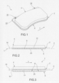
- reference numeral 1 globally denotes a friction assembly comprising a support plate 2, at least one brake pad 4 and at least one reinforcing foil 6 of said plate 2.
- the reinforcing foil 6 has a maximum thickness of about 2 mm.
- the reinforcing foil 6 has a minimum thickness of about 0.5 mm.
- the reinforcing foil 6 is made of metal, such as steel or aluminium.
- the reinforcing foil 6 is made of a composite material, such as a carbon-based material.
- the support plate 2 identifies one or more holes 16 through its thickness suitable to be engaged in a movable manner by guides (not shown) of a brake-caliper, especially upon approaching (and moving away from) a corresponding disc to be braked.
- the reinforcing foil 6 may define lumina 22 at least partially aligned with the holes 16 of the support plate 2.
- the reinforcing foil 6 and support plate 2 extend in a contact plane C between them such that the reinforcing foil 6 remains confined in the profile of the support plate 2, in particular without projecting externally to said plate.
- the reinforcing foil 6 has an extension equal to or smaller than the extension of the support plate 2 in the same plane.
- the aforesaid assembly could comprise at least one protective layer, such as an anti-corrosive layer at least partially covering the reinforcing foil 6.
- the brake pad 4 and the support plate 2 are (preferably hot co-moulded) in at least one heat-resistant resin.
- the heat-resistant resin is a thermosetting resin.
- the heat-resistant resin is a phenolic resin, such as a novolac.
- the heat-resistant resin (or phenol resin) is the same for the support plate 2 and for the brake pads 4.
- the support plate 2 and the brake pad 4 are made from different heat-resistant resins, for example belonging to the same family of polymeric materials.
- the phenolic resin comprises or consists of the resin CAS no. 9003-35-4 .
- the resin is heat resistant at least up to the maximum operating temperature of the assembly 1.
- the heat resistant resin of the support plate 2 is loaded with reinforcing fibres, preferably non-metallic.
- the reinforcing fibres used could comprise carbon fibres, glass fibres, boron fibres, silica fibres, silicon carbide fibres, ceramic fibres and mixtures thereof.
- Glass fibres are a particularly preferred embodiment of this invention.
- the ratio between the weight of heat-resistant resin and the weight of the optional reinforcing fibres could be between 0.1 and 3.0, advantageously between 0.3 and 2.0, optionally between 0.4 and 1.8, for example between 0.7 and 1.5.
- the reinforcing fibres are of a mean length equal to or greater than about 12 mm (for example equal to or greater than 13 or 14 mm) to increase the mechanical strength of the support plate 2, at least compared to a heat-resistant resin plate devoid of the aforesaid fibres.
- the reinforcing fibres are of an average length equal to or greater than about 12 millimetres, for example comprised in the range of 4 - 11 millimetres.
- the reinforcing fibres are oriented mainly or exclusively in a transversal stress direction T of the brake pad 4 (referred to a configuration of correct use of the assembly 1 in a brake caliper for a disc brake).
- the brake pad 4 is instead devoid of reinforcing fibres.
- a preferred embodiment provides, however, that the heat resistant resin of the brake pad 4 comprises at least one friction modifier component.
- the friction modifier component could be selected from a powdered metal (such as copper, iron, aluminium, and/or zinc), an aluminium or silicon oxide, a flaking material (such as graphite or mica), or combinations thereof.
- the separation zone between the support plate 2 and the brake pad 4 has been schematically shown as a net division plane 18 of said components.
- the reinforcing foil 6 is fixed to the support plate 2 by means of anchoring projections 8, joined to and extending away from the foil 6, and are embedded in the aforesaid resin to prevent or limit deformations of the support plate in the use of the assembly 1.
- the anchoring projections 8 could be in the form of a pointed element, a pin, cylinder or hook. According to another embodiment, one or more anchoring projections may be in the form of a cordon or rib.
- the anchoring projections 8 may be shaped as a pyramid, cylinder, truncated cone, cone or truncated pyramid.
- the anchoring projections 8 are made in one piece with the reinforcing foil 6.
- the anchoring projections 8 project only from one surface 10 of the reinforcing foil 6, facing the support plate 2, the opposite surface 20 of such foil being instead without projections.
- the reinforcing foil 6 has no perforations (specifically: through its thickness) in the area superposing the brake pad 4.
- the anchoring projections 8 are distributed on the surface 10 of the reinforcing foil 6 with a density at least equal to, or greater than, about 1-40 projections/cm 2 (for example 1-20 projections/cm 2 ), to achieve a monolithic union between the reinforcing foil 6 and the support plate 2.
- the reinforcing foil in correspondence of the base of at least part of the anchoring projections, could delimit depressions of a substantially complementary shape to said projections.
- the anchoring projections can be generated from the thickness of the reinforcing foil - excavating it in part - thus generating the depressions and projections.
- the brake pad 4 is co-moulded to an opposite surface 12 of the support plate 2 with respect to the surface 14 to which the reinforcing foil 6 is anchored, to create a sandwich structure.
- the present invention also relates to a method of manufacturing a friction assembly.
- a preferred embodiment of the method provides for it to be used to produce a friction assembly 1 according to any one of the preceding embodiments
- preferred or advantageous variants of such method may comprise any step - even implicitly inferable - from the preceding description of the assembly.
- the method comprises the steps of:
- the co-moulding step and the fixing step take place at least partially simultaneously, for example during one or more steps of compression moulding.
- the present invention lastly relates to a brake caliper comprising a friction assembly 1 according to any one of the embodiments illustrated previously, or to an assembly manufactured according to the discussed method.
- a hot press is used with a mould modified so as to delimit two juxtaposed or superposed cavities: a first moulding cavity is intended to receive the heat-resistant resin of the support plate, a second moulding cavity housing instead the heat-resistant resin of the brake pad.
- the reinforcement foil is then placed in the first cavity, after which the heat resistant resin optionally loaded with reinforcing fibres is evenly distributed to fill such cavity.
- a similar or a different heat-resistant resin is placed in the second moulding cavity optionally in the presence of at least one friction modifier component.
- the moulding temperatures may vary between 130°C and 190°C depending on the resins used, while the operating pressures will be in the range 10-50 MPa. Depending on the size of the pad and the quantity of resins used, the moulding times may vary from one to about ten minutes, often 2-5 minutes.
- the moulding of the friction assembly When the moulding of the friction assembly is complete, it is placed in an oven at a temperature of about 220°C to complete the cross-linking of the resin/s.
- the assembly, the caliper and the method described allow the predetermined objectives to be achieved.
- the presence of the reinforcing foil allows an improvement of the thermomechanical resistance and the dimensional stability of the assembly, reducing the overall weight compared to conventional systems.
- the use of a metal reinforcing foil does not involve a drastic increase in weight of the assembly, since the foil utilised has a reduced thickness compared to the overall thickness of the prior metal plates.
- the assembly and the caliper of the present invention allow a substantial reduction in weight to be achieved compared to the traditionally used systems, of course for at least equivalent overall performance.
- the use of a single reinforcing foil allows a saving in weight of the assembly, a reduction of the production cost, and optimized warehouse management to be achieved.
- the method of the present invention allows all the essential components - that is to say the support plate, the brake-pad and the reinforcing foil - to be moulded in a single operation.
- the assembly and the caliper of the present invention are highly reliable, in that the materials of the plate and the brake pad are bonded together in an inseparable manner.
- the assembly and the caliper of the present invention allow the adhesive layer between the plate and the brake pad to be dispensed with, resulting in a favourable impact on production costs and on the reliability of the assembly.
- the assembly of the present invention allows a reduction of the deformations of the plate of about 30% to be achieved compared to the solutions without the reinforcing foil.
- the assembly and the caliper of the present invention are constructively simple and therefore producible at low cost and with repetitive and automated operations.
- the assembly of the present invention has a low heat conductivity, so that the probability of occurrence of vapour lock phenomena of the caliper-brake is reduced.
- the long fibres are much more difficult to form in the heat-resistant resin, they provide unexpected mechanical performance.
Landscapes
- Engineering & Computer Science (AREA)
- General Engineering & Computer Science (AREA)
- Mechanical Engineering (AREA)
- Chemical & Material Sciences (AREA)
- Inorganic Chemistry (AREA)
- Braking Arrangements (AREA)
Claims (13)
- Ensemble de friction (1) comprenant une plaque de support (2), au moins une plaquette de frein (4) et au moins une feuille de renforcement (6) de ladite plaque (2) ;dans lequel la plaquette de frein (4) et la plaque de support (2) sont co-moulées à partir d'au moins une résine résistant à la chaleur, dans lequel la résine résistant à la chaleur de la plaque de support (2) est chargée de fibres de renforcement, de préférence non métalliques,et dans lequel la feuille de renforcement (6) est fixée à la plaque de support (2) à l'aide de saillies d'ancrage (8) reliées à ladite feuille (6) et s'étendant à partir de cette dernière, incorporées dans ladite résine pour empêcher ou limiter des déformations de la plaque de support lors de l'utilisation dudit ensemble (1),dans lequel la plaquette de frein (4) est co-moulée sur une surface opposée (12) de la plaque de support (2) par rapport à la surface (14) à laquelle la feuille de renforcement (6) est ancrée, pour créer une structure en sandwich ;et dans lequel les saillies d'ancrage (8) sont réparties sur une surface (10) de la feuille de renforcement (6) avec une densité au moins égale, ou supérieure à, environ 1-40 saillies/cm2, pour réaliser une union monolithique entre la feuille de renforcement (6) et la plaque de support (2) ;et dans lequel la feuille de renforcement (6) et la plaque de support (2) s'étendent dans un plan de contact C entre elles de sorte que la feuille de renforcement (6) reste confinée dans le profilé de la plaque de support (2), en particulier sans faire saillie à l'extérieur de ladite plaque, dans lequel, à l'intérieur du plan C précédemment mentionné, la feuille de renforcement (6) présente une extension égale à l'extension de la plaque de support (2) dans le même plan.
- Ensemble selon la revendication 1, dans lequel les saillies d'ancrage (8) sont créées d'un seul tenant avec la feuille de renforcement (6).
- Ensemble selon l'une quelconque des revendications précédentes, dans lequel la feuille de renforcement (6) est dépourvue de perforations dans la zone de chevauchement avec la plaquette de frein (4), et dans lequel les saillies d'ancrage (8) font seulement saillie depuis une surface (10) de la feuille de renforcement (6), faisant face à la plaque de support (2).
- Ensemble selon la revendication précédente, dans lequel, en correspondance à la base d'au moins une partie des saillies d'ancrage (8), la feuille de renforcement (6) délimite des creux d'une forme sensiblement complémentaire auxdites saillies.
- Ensemble selon l'une quelconque des revendications précédentes, dans lequel la feuille de renforcement (6) présente une épaisseur maximale d'environ 2 millimètres, et une épaisseur minimale d'environ 0,5 millimètre.
- Ensemble selon l'une quelconque des revendications précédentes, dans lequel la plaque de support (2) identifie, à travers son épaisseur, un ou plusieurs trous (16) appropriés pour être mis en prise par translation par les guides d'un étrier de frein, et dans lequel la feuille de renforcement (6) délimite des ouvertures (22) au moins partiellement alignées sur lesdits trous.
- Ensemble selon l'une quelconque des revendications précédentes, dans lequel la feuille de renforcement (6) est composée d'un matériau métallique, par exemple l'acier, ou d'un matériau composite, par exemple un matériau à base de carbone, et dans lequel ledit ensemble comprend au moins une couche de protection, par exemple anticorrosive, recouvrant au moins partiellement la feuille de renforcement (6).
- Ensemble selon l'une quelconque des revendications précédentes, caractérisé par une résine résistant à la chaleur comprenant ou constituée d'une résine phénolique, par exemple la résine CAS n°9003-35-4.
- Ensemble selon l'une quelconque des revendications précédentes, dans lequel la résine résistant à la chaleur de la plaque de support (2) est partiellement chargée de fibres de renforcement non métalliques, lesdites fibres étant sélectionnées à partir du groupe constitué de fibres de carbone, de fibres de verre, de fibres de bore, de fibres de silice, de fibres de carbure de silicium, de fibres de céramique et de mélanges de celles-ci.
- Ensemble selon la revendication précédente, dans lequel les fibres de renforcement sont d'une longueur moyenne égale ou supérieure à environ 12 millimètres, ou comprise dans la plage de 4 à 11 millimètres.
- Ensemble selon les revendications 9 ou 10, dans lequel les fibres de renforcement sont orientées essentiellement ou exclusivement le long d'une direction de contrainte transversale (T) de ladite plaque de frein (4), dans une configuration d'utilisation correcte dudit ensemble (1) dans un étrier de frein à disque.
- Procédé de fabrication d'un ensemble de friction (1) selon l'une quelconque des revendications précédentes, comprenant les étapes de :- fourniture d'une feuille de renforcement (6) présentant des saillies d'ancrage (8) réparties sur une surface (10) de la feuille de renforcement (6) avec une densité au moins égale, ou supérieure à, environ 1-40 saillies/cm2, pour réaliser une union monolithique entre la feuille de renforcement (6) et la plaque de support (2) ;- co-moulage d'une plaque de support (2) et d'au moins une plaquette de frein (4) à partir d'au moins une résine résistant à la chaleur, dans lequel la résine résistant à la chaleur de la plaque de support (2) est chargée de fibres de renforcement, de préférence non métalliques ;- fixation d'une feuille de renforcement (6) à la plaque de support (2) en incorporant dans ladite résine des saillies d'ancrage (8) reliées à ladite feuille (6) et s'étendant à partir de cette dernière, pour empêcher ou limiter des déformations de la plaque de support lors de l'utilisation dudit ensemble (1),dans lequel la plaquette de frein (4) est co-moulée sur une surface opposée (12) de la plaque de support (2) par rapport à la surface (14) à laquelle la feuille de renforcement (6) est ancrée, pour créer une structure en sandwich ;dans lequel l'étape de co-moulage et l'étape de fixation ont lieu au moins partiellement en même temps, durant une ou plusieurs étapes de moulage par compression.
- Étrier de frein comprenant un ensemble de friction selon les revendications 1 à 11.
Priority Applications (1)
| Application Number | Priority Date | Filing Date | Title |
|---|---|---|---|
| PL17717218.6T PL3414467T5 (pl) | 2016-02-08 | 2017-01-26 | Zespół cierny, zacisk hamulcowy i sposób wytwarzania |
Applications Claiming Priority (2)
| Application Number | Priority Date | Filing Date | Title |
|---|---|---|---|
| ITUB2016A000550A ITUB20160550A1 (it) | 2016-02-08 | 2016-02-08 | Assieme di frizione, pinza-freno e metodo di fabbricazione |
| PCT/IB2017/050403 WO2017137863A1 (fr) | 2016-02-08 | 2017-01-26 | Ensemble de friction, étrier de frein et procédé de fabrication |
Publications (4)
| Publication Number | Publication Date |
|---|---|
| EP3414467A1 EP3414467A1 (fr) | 2018-12-19 |
| EP3414467B1 EP3414467B1 (fr) | 2020-11-25 |
| EP3414467B8 EP3414467B8 (fr) | 2021-09-01 |
| EP3414467B2 true EP3414467B2 (fr) | 2024-04-03 |
Family
ID=55861046
Family Applications (1)
| Application Number | Title | Priority Date | Filing Date |
|---|---|---|---|
| EP17717218.6A Active EP3414467B2 (fr) | 2016-02-08 | 2017-01-26 | Ensemble de friction, étrier de frein et procédé de fabrication |
Country Status (9)
| Country | Link |
|---|---|
| US (1) | US11268583B2 (fr) |
| EP (1) | EP3414467B2 (fr) |
| JP (1) | JP6921090B2 (fr) |
| KR (1) | KR102670119B1 (fr) |
| ES (1) | ES2860770T5 (fr) |
| IT (1) | ITUB20160550A1 (fr) |
| MX (1) | MX2018009598A (fr) |
| PL (1) | PL3414467T5 (fr) |
| WO (1) | WO2017137863A1 (fr) |
Citations (7)
| Publication number | Priority date | Publication date | Assignee | Title |
|---|---|---|---|---|
| US5376410A (en) † | 1991-10-02 | 1994-12-27 | Mackelvie; Winston R. | Material surface modification |
| DE29821482U1 (de) † | 1998-12-02 | 2000-04-13 | AlliedSignal Bremsbelag GmbH, 21509 Glinde | Bremsbelag für Scheibenbremsen |
| EP2204591A1 (fr) † | 2009-01-06 | 2010-07-07 | Shin In Trading Co., Ltd. | Dispositif de freinage avec plateau de frein dentelé |
| WO2011033395A1 (fr) † | 2009-09-17 | 2011-03-24 | Consulplast S.R.L. | Plaquette de frein pour frein à disque de véhicule |
| WO2014087236A1 (fr) † | 2012-12-07 | 2014-06-12 | R.A Investment Management S.A.R.L. | Plaque d'appui de frein à disque composite |
| WO2015010183A1 (fr) † | 2013-07-26 | 2015-01-29 | R.A. Investment Management S.A.R.L | Stratifié de métal et de graphite |
| WO2015173768A1 (fr) † | 2014-05-16 | 2015-11-19 | Freni Brembo S.P.A. | Ensemble de friction, étrier de frein et procédé de fabrication |
Family Cites Families (14)
| Publication number | Priority date | Publication date | Assignee | Title |
|---|---|---|---|---|
| FR2406128A1 (fr) * | 1977-07-25 | 1979-05-11 | Abex Pagid Equip | Procede de fabrication de garnitures pour freins a disques |
| GB2311569B (en) * | 1996-03-27 | 2000-10-25 | Luk Lamellen & Kupplungsbau | Friction lining |
| US6022502A (en) * | 1997-09-30 | 2000-02-08 | Lockhart; Wayne | Composite friction assembly |
| JP2001165210A (ja) * | 1999-12-14 | 2001-06-19 | Nisshinbo Ind Inc | ディスクブレーキ、ディスクブレーキパッド、及び該ディスクブレーキパッド用バックプレート |
| US20030155193A1 (en) * | 2002-02-20 | 2003-08-21 | Hays William D. | Non-metallic brake plate |
| US20050161297A1 (en) * | 2004-01-23 | 2005-07-28 | Innovative Technologies, Llc | Brake pad backing plate and method of making the same |
| CN102138022B (zh) | 2008-08-08 | 2015-06-10 | 福乐尼·乐姆宝公开有限公司 | 用于制动器的摩擦组件的陶瓷基体材料的制备方法及其制得的陶瓷基体材料 |
| WO2010033538A2 (fr) * | 2008-09-18 | 2010-03-25 | Hawk Corporation | Composite a matrice en carbone renforce par des fibres de carbone pour plaque arriere de patin de frein |
| CN105008750A (zh) * | 2013-03-12 | 2015-10-28 | 住友电木株式会社 | 制动片和卡钳装置 |
| US9689450B2 (en) * | 2014-09-26 | 2017-06-27 | R.A. Investment Management S.A.R.L. | Composite disc brake backing plate |
| US9360067B1 (en) * | 2015-02-05 | 2016-06-07 | R. A. Investment Management S.A.R.L. | Hybrid laminate |
| CA2921061C (fr) * | 2015-06-10 | 2022-10-18 | Ray Arbesman | Patin de frein dote de cale et de coussin de friction multicouche preformes |
| US10344817B2 (en) * | 2015-11-30 | 2019-07-09 | Hyundai Motor Company | Vehicle brake pad |
| CA3017768C (fr) * | 2016-04-14 | 2024-02-06 | Nucap Industries Inc. | Composite metallique multicouche et plaquette de frein le comprenant |
-
2016
- 2016-02-08 IT ITUB2016A000550A patent/ITUB20160550A1/it unknown
-
2017
- 2017-01-26 ES ES17717218T patent/ES2860770T5/es active Active
- 2017-01-26 WO PCT/IB2017/050403 patent/WO2017137863A1/fr not_active Ceased
- 2017-01-26 US US16/076,075 patent/US11268583B2/en active Active
- 2017-01-26 EP EP17717218.6A patent/EP3414467B2/fr active Active
- 2017-01-26 MX MX2018009598A patent/MX2018009598A/es unknown
- 2017-01-26 JP JP2018538610A patent/JP6921090B2/ja active Active
- 2017-01-26 KR KR1020187025133A patent/KR102670119B1/ko active Active
- 2017-01-26 PL PL17717218.6T patent/PL3414467T5/pl unknown
Patent Citations (8)
| Publication number | Priority date | Publication date | Assignee | Title |
|---|---|---|---|---|
| US5376410A (en) † | 1991-10-02 | 1994-12-27 | Mackelvie; Winston R. | Material surface modification |
| DE29821482U1 (de) † | 1998-12-02 | 2000-04-13 | AlliedSignal Bremsbelag GmbH, 21509 Glinde | Bremsbelag für Scheibenbremsen |
| EP1006289A2 (fr) † | 1998-12-02 | 2000-06-07 | AlliedSignal Bremsbelag GmbH | Garniture de frein pour freins à disque |
| EP2204591A1 (fr) † | 2009-01-06 | 2010-07-07 | Shin In Trading Co., Ltd. | Dispositif de freinage avec plateau de frein dentelé |
| WO2011033395A1 (fr) † | 2009-09-17 | 2011-03-24 | Consulplast S.R.L. | Plaquette de frein pour frein à disque de véhicule |
| WO2014087236A1 (fr) † | 2012-12-07 | 2014-06-12 | R.A Investment Management S.A.R.L. | Plaque d'appui de frein à disque composite |
| WO2015010183A1 (fr) † | 2013-07-26 | 2015-01-29 | R.A. Investment Management S.A.R.L | Stratifié de métal et de graphite |
| WO2015173768A1 (fr) † | 2014-05-16 | 2015-11-19 | Freni Brembo S.P.A. | Ensemble de friction, étrier de frein et procédé de fabrication |
Also Published As
| Publication number | Publication date |
|---|---|
| EP3414467B8 (fr) | 2021-09-01 |
| ES2860770T3 (es) | 2021-10-05 |
| KR20180108765A (ko) | 2018-10-04 |
| ES2860770T5 (es) | 2024-11-12 |
| MX2018009598A (es) | 2018-12-17 |
| JP6921090B2 (ja) | 2021-08-18 |
| ITUB20160550A1 (it) | 2017-08-08 |
| WO2017137863A1 (fr) | 2017-08-17 |
| US11268583B2 (en) | 2022-03-08 |
| EP3414467A1 (fr) | 2018-12-19 |
| KR102670119B1 (ko) | 2024-05-28 |
| PL3414467T5 (pl) | 2024-11-04 |
| JP2019504262A (ja) | 2019-02-14 |
| PL3414467T3 (pl) | 2021-06-28 |
| CA3012286A1 (fr) | 2017-08-17 |
| US20190186570A1 (en) | 2019-06-20 |
| EP3414467B1 (fr) | 2020-11-25 |
Similar Documents
| Publication | Publication Date | Title |
|---|---|---|
| US10119583B2 (en) | Friction assembly, brake calliper and manufacturing method | |
| CN102575736A (zh) | 用于车辆盘式制动器的制动块 | |
| WO2005069972A3 (fr) | Assemblage de rotor pour freins à disques et son procédé de fabrication | |
| JP2013053687A (ja) | ブレーキパッド | |
| EP1272772B1 (fr) | Composants de freinage destines particulierement a des freins de vehicules | |
| US3761231A (en) | Composite articles | |
| CA3002054C (fr) | Isolant haute friction | |
| JP2012211675A (ja) | ブレーキパッド | |
| EP3414467B2 (fr) | Ensemble de friction, étrier de frein et procédé de fabrication | |
| JPH02271120A (ja) | ディスクブレーキパッド及びその製造方法 | |
| CA3012286C (fr) | Ensemble de friction, etrier de frein et procede de fabrication | |
| JP2013057337A (ja) | ブレーキパッドおよびその製造方法 | |
| KR101610131B1 (ko) | 자동차 브레이크 디스크 제조 방법 | |
| WO2021123755A1 (fr) | Disque de frein, procédé de fabrication de ce dernier et plaquette | |
| JP2013053688A (ja) | ブレーキパッド | |
| KR101258828B1 (ko) | 탄소-세라믹 브레이크 디스크 및 그 제작방법 및 그 제작방법에 사용되는 다기능 코어 | |
| JP4338874B2 (ja) | 車両用ディスクブレーキの摩擦パッド | |
| KR102184578B1 (ko) | 차량 브레이크패드용 백플레이트 전용가공 파인블랭킹금형장치 | |
| US8596429B2 (en) | Brake disk comprising a ceramic friction ring | |
| TWI896144B (zh) | 剎車片與其製造方法 | |
| JP2665624B2 (ja) | 車両用ディスクブレーキの摩擦パッド | |
| JP2019157925A (ja) | ディスクブレーキパッドの製造方法、ディスクブレーキパッド及びディスクブレーキパッドの摩擦部材用金型 | |
| WO1995009251A1 (fr) | Composites a matrice metallique | |
| CA2999300A1 (fr) | Rotor de frein en composite | |
| JP2019504262A5 (fr) |
Legal Events
| Date | Code | Title | Description |
|---|---|---|---|
| STAA | Information on the status of an ep patent application or granted ep patent |
Free format text: STATUS: UNKNOWN |
|
| STAA | Information on the status of an ep patent application or granted ep patent |
Free format text: STATUS: THE INTERNATIONAL PUBLICATION HAS BEEN MADE |
|
| PUAI | Public reference made under article 153(3) epc to a published international application that has entered the european phase |
Free format text: ORIGINAL CODE: 0009012 |
|
| STAA | Information on the status of an ep patent application or granted ep patent |
Free format text: STATUS: REQUEST FOR EXAMINATION WAS MADE |
|
| 17P | Request for examination filed |
Effective date: 20180802 |
|
| AK | Designated contracting states |
Kind code of ref document: A1 Designated state(s): AL AT BE BG CH CY CZ DE DK EE ES FI FR GB GR HR HU IE IS IT LI LT LU LV MC MK MT NL NO PL PT RO RS SE SI SK SM TR |
|
| AX | Request for extension of the european patent |
Extension state: BA ME |
|
| DAV | Request for validation of the european patent (deleted) | ||
| DAX | Request for extension of the european patent (deleted) | ||
| STAA | Information on the status of an ep patent application or granted ep patent |
Free format text: STATUS: EXAMINATION IS IN PROGRESS |
|
| 17Q | First examination report despatched |
Effective date: 20191122 |
|
| GRAP | Despatch of communication of intention to grant a patent |
Free format text: ORIGINAL CODE: EPIDOSNIGR1 |
|
| STAA | Information on the status of an ep patent application or granted ep patent |
Free format text: STATUS: GRANT OF PATENT IS INTENDED |
|
| INTG | Intention to grant announced |
Effective date: 20200707 |
|
| GRAS | Grant fee paid |
Free format text: ORIGINAL CODE: EPIDOSNIGR3 |
|
| GRAA | (expected) grant |
Free format text: ORIGINAL CODE: 0009210 |
|
| STAA | Information on the status of an ep patent application or granted ep patent |
Free format text: STATUS: THE PATENT HAS BEEN GRANTED |
|
| AK | Designated contracting states |
Kind code of ref document: B1 Designated state(s): AL AT BE BG CH CY CZ DE DK EE ES FI FR GB GR HR HU IE IS IT LI LT LU LV MC MK MT NL NO PL PT RO RS SE SI SK SM TR |
|
| REG | Reference to a national code |
Ref country code: GB Ref legal event code: FG4D |
|
| REG | Reference to a national code |
Ref country code: CH Ref legal event code: EP |
|
| REG | Reference to a national code |
Ref country code: AT Ref legal event code: REF Ref document number: 1338683 Country of ref document: AT Kind code of ref document: T Effective date: 20201215 |
|
| REG | Reference to a national code |
Ref country code: DE Ref legal event code: R096 Ref document number: 602017028230 Country of ref document: DE |
|
| REG | Reference to a national code |
Ref country code: IE Ref legal event code: FG4D |
|
| REG | Reference to a national code |
Ref country code: RO Ref legal event code: EPE |
|
| REG | Reference to a national code |
Ref country code: NL Ref legal event code: MP Effective date: 20201125 |
|
| PG25 | Lapsed in a contracting state [announced via postgrant information from national office to epo] |
Ref country code: NO Free format text: LAPSE BECAUSE OF FAILURE TO SUBMIT A TRANSLATION OF THE DESCRIPTION OR TO PAY THE FEE WITHIN THE PRESCRIBED TIME-LIMIT Effective date: 20210225 Ref country code: PT Free format text: LAPSE BECAUSE OF FAILURE TO SUBMIT A TRANSLATION OF THE DESCRIPTION OR TO PAY THE FEE WITHIN THE PRESCRIBED TIME-LIMIT Effective date: 20210325 Ref country code: RS Free format text: LAPSE BECAUSE OF FAILURE TO SUBMIT A TRANSLATION OF THE DESCRIPTION OR TO PAY THE FEE WITHIN THE PRESCRIBED TIME-LIMIT Effective date: 20201125 Ref country code: FI Free format text: LAPSE BECAUSE OF FAILURE TO SUBMIT A TRANSLATION OF THE DESCRIPTION OR TO PAY THE FEE WITHIN THE PRESCRIBED TIME-LIMIT Effective date: 20201125 Ref country code: GR Free format text: LAPSE BECAUSE OF FAILURE TO SUBMIT A TRANSLATION OF THE DESCRIPTION OR TO PAY THE FEE WITHIN THE PRESCRIBED TIME-LIMIT Effective date: 20210226 |
|
| PG25 | Lapsed in a contracting state [announced via postgrant information from national office to epo] |
Ref country code: SE Free format text: LAPSE BECAUSE OF FAILURE TO SUBMIT A TRANSLATION OF THE DESCRIPTION OR TO PAY THE FEE WITHIN THE PRESCRIBED TIME-LIMIT Effective date: 20201125 Ref country code: BG Free format text: LAPSE BECAUSE OF FAILURE TO SUBMIT A TRANSLATION OF THE DESCRIPTION OR TO PAY THE FEE WITHIN THE PRESCRIBED TIME-LIMIT Effective date: 20210225 Ref country code: IS Free format text: LAPSE BECAUSE OF FAILURE TO SUBMIT A TRANSLATION OF THE DESCRIPTION OR TO PAY THE FEE WITHIN THE PRESCRIBED TIME-LIMIT Effective date: 20210325 Ref country code: LV Free format text: LAPSE BECAUSE OF FAILURE TO SUBMIT A TRANSLATION OF THE DESCRIPTION OR TO PAY THE FEE WITHIN THE PRESCRIBED TIME-LIMIT Effective date: 20201125 |
|
| REG | Reference to a national code |
Ref country code: LT Ref legal event code: MG9D |
|
| PG25 | Lapsed in a contracting state [announced via postgrant information from national office to epo] |
Ref country code: HR Free format text: LAPSE BECAUSE OF FAILURE TO SUBMIT A TRANSLATION OF THE DESCRIPTION OR TO PAY THE FEE WITHIN THE PRESCRIBED TIME-LIMIT Effective date: 20201125 |
|
| RAP4 | Party data changed (patent owner data changed or rights of a patent transferred) |
Owner name: BREMBO S.P.A. |
|
| RIN2 | Information on inventor provided after grant (corrected) |
Inventor name: MAESTRINI, LUCA Inventor name: VAROTTO, PAOLO Inventor name: GAVAZZI, ANDREA |
|
| PG25 | Lapsed in a contracting state [announced via postgrant information from national office to epo] |
Ref country code: SM Free format text: LAPSE BECAUSE OF FAILURE TO SUBMIT A TRANSLATION OF THE DESCRIPTION OR TO PAY THE FEE WITHIN THE PRESCRIBED TIME-LIMIT Effective date: 20201125 Ref country code: LT Free format text: LAPSE BECAUSE OF FAILURE TO SUBMIT A TRANSLATION OF THE DESCRIPTION OR TO PAY THE FEE WITHIN THE PRESCRIBED TIME-LIMIT Effective date: 20201125 Ref country code: EE Free format text: LAPSE BECAUSE OF FAILURE TO SUBMIT A TRANSLATION OF THE DESCRIPTION OR TO PAY THE FEE WITHIN THE PRESCRIBED TIME-LIMIT Effective date: 20201125 Ref country code: CZ Free format text: LAPSE BECAUSE OF FAILURE TO SUBMIT A TRANSLATION OF THE DESCRIPTION OR TO PAY THE FEE WITHIN THE PRESCRIBED TIME-LIMIT Effective date: 20201125 Ref country code: SK Free format text: LAPSE BECAUSE OF FAILURE TO SUBMIT A TRANSLATION OF THE DESCRIPTION OR TO PAY THE FEE WITHIN THE PRESCRIBED TIME-LIMIT Effective date: 20201125 |
|
| REG | Reference to a national code |
Ref country code: CH Ref legal event code: PK Free format text: BERICHTIGUNGEN |
|
| REG | Reference to a national code |
Ref country code: CH Ref legal event code: PK Free format text: BERICHTIGUNG B8 |
|
| REG | Reference to a national code |
Ref country code: DE Ref legal event code: R026 Ref document number: 602017028230 Country of ref document: DE |
|
| RAP4 | Party data changed (patent owner data changed or rights of a patent transferred) |
Owner name: BREMBO S.P.A. |
|
| RIN2 | Information on inventor provided after grant (corrected) |
Inventor name: MAESTRINI, LUCA Inventor name: VAROTTO, PAOLO Inventor name: GAVAZZI, ANDREA |
|
| PLBI | Opposition filed |
Free format text: ORIGINAL CODE: 0009260 |
|
| PG25 | Lapsed in a contracting state [announced via postgrant information from national office to epo] |
Ref country code: MC Free format text: LAPSE BECAUSE OF FAILURE TO SUBMIT A TRANSLATION OF THE DESCRIPTION OR TO PAY THE FEE WITHIN THE PRESCRIBED TIME-LIMIT Effective date: 20201125 Ref country code: DK Free format text: LAPSE BECAUSE OF FAILURE TO SUBMIT A TRANSLATION OF THE DESCRIPTION OR TO PAY THE FEE WITHIN THE PRESCRIBED TIME-LIMIT Effective date: 20201125 |
|
| REG | Reference to a national code |
Ref country code: CH Ref legal event code: PL |
|
| PLAX | Notice of opposition and request to file observation + time limit sent |
Free format text: ORIGINAL CODE: EPIDOSNOBS2 |
|
| 26 | Opposition filed |
Opponent name: VRI-VERBAND DER REIBBELAGINDUSTRIE E.V. Effective date: 20210824 |
|
| PG25 | Lapsed in a contracting state [announced via postgrant information from national office to epo] |
Ref country code: LU Free format text: LAPSE BECAUSE OF NON-PAYMENT OF DUE FEES Effective date: 20210126 |
|
| GBPC | Gb: european patent ceased through non-payment of renewal fee |
Effective date: 20210225 |
|
| PG25 | Lapsed in a contracting state [announced via postgrant information from national office to epo] |
Ref country code: AL Free format text: LAPSE BECAUSE OF FAILURE TO SUBMIT A TRANSLATION OF THE DESCRIPTION OR TO PAY THE FEE WITHIN THE PRESCRIBED TIME-LIMIT Effective date: 20201125 Ref country code: NL Free format text: LAPSE BECAUSE OF FAILURE TO SUBMIT A TRANSLATION OF THE DESCRIPTION OR TO PAY THE FEE WITHIN THE PRESCRIBED TIME-LIMIT Effective date: 20201125 Ref country code: IT Free format text: LAPSE BECAUSE OF FAILURE TO SUBMIT A TRANSLATION OF THE DESCRIPTION OR TO PAY THE FEE WITHIN THE PRESCRIBED TIME-LIMIT Effective date: 20201125 |
|
| PG25 | Lapsed in a contracting state [announced via postgrant information from national office to epo] |
Ref country code: LI Free format text: LAPSE BECAUSE OF NON-PAYMENT OF DUE FEES Effective date: 20210131 Ref country code: SI Free format text: LAPSE BECAUSE OF FAILURE TO SUBMIT A TRANSLATION OF THE DESCRIPTION OR TO PAY THE FEE WITHIN THE PRESCRIBED TIME-LIMIT Effective date: 20201125 Ref country code: CH Free format text: LAPSE BECAUSE OF NON-PAYMENT OF DUE FEES Effective date: 20210131 |
|
| PLBB | Reply of patent proprietor to notice(s) of opposition received |
Free format text: ORIGINAL CODE: EPIDOSNOBS3 |
|
| PG25 | Lapsed in a contracting state [announced via postgrant information from national office to epo] |
Ref country code: GB Free format text: LAPSE BECAUSE OF NON-PAYMENT OF DUE FEES Effective date: 20210225 Ref country code: IE Free format text: LAPSE BECAUSE OF NON-PAYMENT OF DUE FEES Effective date: 20210126 |
|
| PG25 | Lapsed in a contracting state [announced via postgrant information from national office to epo] |
Ref country code: IS Free format text: LAPSE BECAUSE OF FAILURE TO SUBMIT A TRANSLATION OF THE DESCRIPTION OR TO PAY THE FEE WITHIN THE PRESCRIBED TIME-LIMIT Effective date: 20210325 |
|
| REG | Reference to a national code |
Ref country code: DE Ref legal event code: R081 Ref document number: 602017028230 Country of ref document: DE Owner name: BREMBO S.P.A., CURNO, IT Free format text: FORMER OWNER: FRENI BREMBO S.P.A., CURNO, BERGAMO, IT |
|
| PG25 | Lapsed in a contracting state [announced via postgrant information from national office to epo] |
Ref country code: CY Free format text: LAPSE BECAUSE OF FAILURE TO SUBMIT A TRANSLATION OF THE DESCRIPTION OR TO PAY THE FEE WITHIN THE PRESCRIBED TIME-LIMIT Effective date: 20201125 |
|
| P01 | Opt-out of the competence of the unified patent court (upc) registered |
Effective date: 20230526 |
|
| PG25 | Lapsed in a contracting state [announced via postgrant information from national office to epo] |
Ref country code: HU Free format text: LAPSE BECAUSE OF FAILURE TO SUBMIT A TRANSLATION OF THE DESCRIPTION OR TO PAY THE FEE WITHIN THE PRESCRIBED TIME-LIMIT; INVALID AB INITIO Effective date: 20170126 |
|
| PUAH | Patent maintained in amended form |
Free format text: ORIGINAL CODE: 0009272 |
|
| STAA | Information on the status of an ep patent application or granted ep patent |
Free format text: STATUS: PATENT MAINTAINED AS AMENDED |
|
| 27A | Patent maintained in amended form |
Effective date: 20240403 |
|
| AK | Designated contracting states |
Kind code of ref document: B2 Designated state(s): AL AT BE BG CH CY CZ DE DK EE ES FI FR GB GR HR HU IE IS IT LI LT LU LV MC MK MT NL NO PL PT RO RS SE SI SK SM TR |
|
| REG | Reference to a national code |
Ref country code: DE Ref legal event code: R102 Ref document number: 602017028230 Country of ref document: DE |
|
| PG25 | Lapsed in a contracting state [announced via postgrant information from national office to epo] |
Ref country code: MK Free format text: LAPSE BECAUSE OF FAILURE TO SUBMIT A TRANSLATION OF THE DESCRIPTION OR TO PAY THE FEE WITHIN THE PRESCRIBED TIME-LIMIT Effective date: 20201125 |
|
| REG | Reference to a national code |
Ref country code: AT Ref legal event code: UEP Ref document number: 1338683 Country of ref document: AT Kind code of ref document: T Effective date: 20201125 |
|
| PG25 | Lapsed in a contracting state [announced via postgrant information from national office to epo] |
Ref country code: MT Free format text: LAPSE BECAUSE OF FAILURE TO SUBMIT A TRANSLATION OF THE DESCRIPTION OR TO PAY THE FEE WITHIN THE PRESCRIBED TIME-LIMIT Effective date: 20201125 |
|
| REG | Reference to a national code |
Ref country code: ES Ref legal event code: DC2A Ref document number: 2860770 Country of ref document: ES Kind code of ref document: T5 Effective date: 20241112 |
|
| PGFP | Annual fee paid to national office [announced via postgrant information from national office to epo] |
Ref country code: PL Payment date: 20250120 Year of fee payment: 9 |
|
| PG25 | Lapsed in a contracting state [announced via postgrant information from national office to epo] |
Ref country code: TR Free format text: LAPSE BECAUSE OF FAILURE TO SUBMIT A TRANSLATION OF THE DESCRIPTION OR TO PAY THE FEE WITHIN THE PRESCRIBED TIME-LIMIT Effective date: 20201125 |
|
| PGFP | Annual fee paid to national office [announced via postgrant information from national office to epo] |
Ref country code: ES Payment date: 20260202 Year of fee payment: 10 |
|
| PGFP | Annual fee paid to national office [announced via postgrant information from national office to epo] |
Ref country code: DE Payment date: 20260123 Year of fee payment: 10 |
|
| PGFP | Annual fee paid to national office [announced via postgrant information from national office to epo] |
Ref country code: AT Payment date: 20251223 Year of fee payment: 10 |
|
| PGFP | Annual fee paid to national office [announced via postgrant information from national office to epo] |
Ref country code: RO Payment date: 20260120 Year of fee payment: 10 Ref country code: BE Payment date: 20260121 Year of fee payment: 10 |
|
| PGFP | Annual fee paid to national office [announced via postgrant information from national office to epo] |
Ref country code: FR Payment date: 20260130 Year of fee payment: 10 |