EP3414616B1 - Dispositif visiocasque, système et procédé correspondants - Google Patents
Dispositif visiocasque, système et procédé correspondants Download PDFInfo
- Publication number
- EP3414616B1 EP3414616B1 EP18737795.7A EP18737795A EP3414616B1 EP 3414616 B1 EP3414616 B1 EP 3414616B1 EP 18737795 A EP18737795 A EP 18737795A EP 3414616 B1 EP3414616 B1 EP 3414616B1
- Authority
- EP
- European Patent Office
- Prior art keywords
- symbol
- display device
- vehicle
- coordinate system
- xyz
- Prior art date
- Legal status (The legal status is an assumption and is not a legal conclusion. Google has not performed a legal analysis and makes no representation as to the accuracy of the status listed.)
- Active
Links
Images












Classifications
-
- G—PHYSICS
- G09—EDUCATION; CRYPTOGRAPHY; DISPLAY; ADVERTISING; SEALS
- G09G—ARRANGEMENTS OR CIRCUITS FOR CONTROL OF INDICATING DEVICES USING STATIC MEANS TO PRESENT VARIABLE INFORMATION
- G09G5/00—Control arrangements or circuits for visual indicators common to cathode-ray tube indicators and other visual indicators
- G09G5/36—Control arrangements or circuits for visual indicators common to cathode-ray tube indicators and other visual indicators characterised by the display of a graphic pattern, e.g. using an all-points-addressable [APA] memory
- G09G5/37—Details of the operation on graphic patterns
-
- G—PHYSICS
- G06—COMPUTING OR CALCULATING; COUNTING
- G06F—ELECTRIC DIGITAL DATA PROCESSING
- G06F3/00—Input arrangements for transferring data to be processed into a form capable of being handled by the computer; Output arrangements for transferring data from processing unit to output unit, e.g. interface arrangements
- G06F3/01—Input arrangements or combined input and output arrangements for interaction between user and computer
- G06F3/011—Arrangements for interaction with the human body, e.g. for user immersion in virtual reality
- G06F3/013—Eye tracking input arrangements
-
- B—PERFORMING OPERATIONS; TRANSPORTING
- B60—VEHICLES IN GENERAL
- B60K—ARRANGEMENT OR MOUNTING OF PROPULSION UNITS OR OF TRANSMISSIONS IN VEHICLES; ARRANGEMENT OR MOUNTING OF PLURAL DIVERSE PRIME-MOVERS IN VEHICLES; AUXILIARY DRIVES FOR VEHICLES; INSTRUMENTATION OR DASHBOARDS FOR VEHICLES; ARRANGEMENTS IN CONNECTION WITH COOLING, AIR INTAKE, GAS EXHAUST OR FUEL SUPPLY OF PROPULSION UNITS IN VEHICLES
- B60K35/00—Instruments specially adapted for vehicles; Arrangement of instruments in or on vehicles
- B60K35/20—Output arrangements, i.e. from vehicle to user, associated with vehicle functions or specially adapted therefor
- B60K35/29—Instruments characterised by the way in which information is handled, e.g. showing information on plural displays or prioritising information according to driving conditions
-
- B—PERFORMING OPERATIONS; TRANSPORTING
- B60—VEHICLES IN GENERAL
- B60K—ARRANGEMENT OR MOUNTING OF PROPULSION UNITS OR OF TRANSMISSIONS IN VEHICLES; ARRANGEMENT OR MOUNTING OF PLURAL DIVERSE PRIME-MOVERS IN VEHICLES; AUXILIARY DRIVES FOR VEHICLES; INSTRUMENTATION OR DASHBOARDS FOR VEHICLES; ARRANGEMENTS IN CONNECTION WITH COOLING, AIR INTAKE, GAS EXHAUST OR FUEL SUPPLY OF PROPULSION UNITS IN VEHICLES
- B60K35/00—Instruments specially adapted for vehicles; Arrangement of instruments in or on vehicles
- B60K35/80—Arrangements for controlling instruments
- B60K35/81—Arrangements for controlling instruments for controlling displays
-
- B—PERFORMING OPERATIONS; TRANSPORTING
- B64—AIRCRAFT; AVIATION; COSMONAUTICS
- B64D—EQUIPMENT FOR FITTING IN OR TO AIRCRAFT; FLIGHT SUITS; PARACHUTES; ARRANGEMENT OR MOUNTING OF POWER PLANTS OR PROPULSION TRANSMISSIONS IN AIRCRAFT
- B64D43/00—Arrangements or adaptations of instruments
-
- G—PHYSICS
- G01—MEASURING; TESTING
- G01C—MEASURING DISTANCES, LEVELS OR BEARINGS; SURVEYING; NAVIGATION; GYROSCOPIC INSTRUMENTS; PHOTOGRAMMETRY OR VIDEOGRAMMETRY
- G01C23/00—Combined instruments indicating more than one navigational value, e.g. for aircraft; Combined measuring devices for measuring two or more variables of movement, e.g. distance, speed or acceleration
- G01C23/005—Flight directors
-
- G—PHYSICS
- G02—OPTICS
- G02B—OPTICAL ELEMENTS, SYSTEMS OR APPARATUS
- G02B27/00—Optical systems or apparatus not provided for by any of the groups G02B1/00 - G02B26/00, G02B30/00
-
- G—PHYSICS
- G02—OPTICS
- G02B—OPTICAL ELEMENTS, SYSTEMS OR APPARATUS
- G02B27/00—Optical systems or apparatus not provided for by any of the groups G02B1/00 - G02B26/00, G02B30/00
- G02B27/01—Head-up displays
- G02B27/017—Head mounted
-
- G—PHYSICS
- G06—COMPUTING OR CALCULATING; COUNTING
- G06F—ELECTRIC DIGITAL DATA PROCESSING
- G06F3/00—Input arrangements for transferring data to be processed into a form capable of being handled by the computer; Output arrangements for transferring data from processing unit to output unit, e.g. interface arrangements
- G06F3/01—Input arrangements or combined input and output arrangements for interaction between user and computer
- G06F3/011—Arrangements for interaction with the human body, e.g. for user immersion in virtual reality
-
- G—PHYSICS
- G06—COMPUTING OR CALCULATING; COUNTING
- G06T—IMAGE DATA PROCESSING OR GENERATION, IN GENERAL
- G06T11/00—Two-dimensional [2D] image generation
- G06T11/60—Creating or editing images; Combining images with text
-
- G—PHYSICS
- G09—EDUCATION; CRYPTOGRAPHY; DISPLAY; ADVERTISING; SEALS
- G09G—ARRANGEMENTS OR CIRCUITS FOR CONTROL OF INDICATING DEVICES USING STATIC MEANS TO PRESENT VARIABLE INFORMATION
- G09G5/00—Control arrangements or circuits for visual indicators common to cathode-ray tube indicators and other visual indicators
- G09G5/36—Control arrangements or circuits for visual indicators common to cathode-ray tube indicators and other visual indicators characterised by the display of a graphic pattern, e.g. using an all-points-addressable [APA] memory
- G09G5/38—Control arrangements or circuits for visual indicators common to cathode-ray tube indicators and other visual indicators characterised by the display of a graphic pattern, e.g. using an all-points-addressable [APA] memory with means for controlling the display position
-
- B—PERFORMING OPERATIONS; TRANSPORTING
- B60—VEHICLES IN GENERAL
- B60K—ARRANGEMENT OR MOUNTING OF PROPULSION UNITS OR OF TRANSMISSIONS IN VEHICLES; ARRANGEMENT OR MOUNTING OF PLURAL DIVERSE PRIME-MOVERS IN VEHICLES; AUXILIARY DRIVES FOR VEHICLES; INSTRUMENTATION OR DASHBOARDS FOR VEHICLES; ARRANGEMENTS IN CONNECTION WITH COOLING, AIR INTAKE, GAS EXHAUST OR FUEL SUPPLY OF PROPULSION UNITS IN VEHICLES
- B60K2360/00—Indexing scheme associated with groups B60K35/00 or B60K37/00 relating to details of instruments or dashboards
- B60K2360/20—Optical features of instruments
- B60K2360/33—Illumination features
- B60K2360/334—Projection means
-
- B—PERFORMING OPERATIONS; TRANSPORTING
- B60—VEHICLES IN GENERAL
- B60K—ARRANGEMENT OR MOUNTING OF PROPULSION UNITS OR OF TRANSMISSIONS IN VEHICLES; ARRANGEMENT OR MOUNTING OF PLURAL DIVERSE PRIME-MOVERS IN VEHICLES; AUXILIARY DRIVES FOR VEHICLES; INSTRUMENTATION OR DASHBOARDS FOR VEHICLES; ARRANGEMENTS IN CONNECTION WITH COOLING, AIR INTAKE, GAS EXHAUST OR FUEL SUPPLY OF PROPULSION UNITS IN VEHICLES
- B60K35/00—Instruments specially adapted for vehicles; Arrangement of instruments in or on vehicles
- B60K35/10—Input arrangements, i.e. from user to vehicle, associated with vehicle functions or specially adapted therefor
-
- B—PERFORMING OPERATIONS; TRANSPORTING
- B60—VEHICLES IN GENERAL
- B60K—ARRANGEMENT OR MOUNTING OF PROPULSION UNITS OR OF TRANSMISSIONS IN VEHICLES; ARRANGEMENT OR MOUNTING OF PLURAL DIVERSE PRIME-MOVERS IN VEHICLES; AUXILIARY DRIVES FOR VEHICLES; INSTRUMENTATION OR DASHBOARDS FOR VEHICLES; ARRANGEMENTS IN CONNECTION WITH COOLING, AIR INTAKE, GAS EXHAUST OR FUEL SUPPLY OF PROPULSION UNITS IN VEHICLES
- B60K35/00—Instruments specially adapted for vehicles; Arrangement of instruments in or on vehicles
- B60K35/20—Output arrangements, i.e. from vehicle to user, associated with vehicle functions or specially adapted therefor
- B60K35/21—Output arrangements, i.e. from vehicle to user, associated with vehicle functions or specially adapted therefor using visual output, e.g. blinking lights or matrix displays
- B60K35/22—Display screens
-
- G—PHYSICS
- G02—OPTICS
- G02B—OPTICAL ELEMENTS, SYSTEMS OR APPARATUS
- G02B27/00—Optical systems or apparatus not provided for by any of the groups G02B1/00 - G02B26/00, G02B30/00
- G02B27/01—Head-up displays
- G02B27/0101—Head-up displays characterised by optical features
- G02B2027/014—Head-up displays characterised by optical features comprising information/image processing systems
-
- G—PHYSICS
- G02—OPTICS
- G02B—OPTICAL ELEMENTS, SYSTEMS OR APPARATUS
- G02B27/00—Optical systems or apparatus not provided for by any of the groups G02B1/00 - G02B26/00, G02B30/00
- G02B27/01—Head-up displays
- G02B27/0101—Head-up displays characterised by optical features
- G02B2027/0141—Head-up displays characterised by optical features characterised by the informative content of the display
-
- G—PHYSICS
- G02—OPTICS
- G02B—OPTICAL ELEMENTS, SYSTEMS OR APPARATUS
- G02B27/00—Optical systems or apparatus not provided for by any of the groups G02B1/00 - G02B26/00, G02B30/00
- G02B27/01—Head-up displays
- G02B27/0179—Display position adjusting means not related to the information to be displayed
- G02B2027/0187—Display position adjusting means not related to the information to be displayed slaved to motion of at least a part of the body of the user, e.g. head, eye
-
- G—PHYSICS
- G02—OPTICS
- G02B—OPTICAL ELEMENTS, SYSTEMS OR APPARATUS
- G02B27/00—Optical systems or apparatus not provided for by any of the groups G02B1/00 - G02B26/00, G02B30/00
- G02B27/01—Head-up displays
- G02B27/017—Head mounted
- G02B27/0172—Head mounted characterised by optical features
-
- G—PHYSICS
- G06—COMPUTING OR CALCULATING; COUNTING
- G06F—ELECTRIC DIGITAL DATA PROCESSING
- G06F3/00—Input arrangements for transferring data to be processed into a form capable of being handled by the computer; Output arrangements for transferring data from processing unit to output unit, e.g. interface arrangements
- G06F3/01—Input arrangements or combined input and output arrangements for interaction between user and computer
- G06F3/048—Interaction techniques based on graphical user interfaces [GUI]
- G06F3/0484—Interaction techniques based on graphical user interfaces [GUI] for the control of specific functions or operations, e.g. selecting or manipulating an object, an image or a displayed text element, setting a parameter value or selecting a range
- G06F3/04842—Selection of displayed objects or displayed text elements
-
- G—PHYSICS
- G06—COMPUTING OR CALCULATING; COUNTING
- G06T—IMAGE DATA PROCESSING OR GENERATION, IN GENERAL
- G06T2200/00—Indexing scheme for image data processing or generation, in general
- G06T2200/24—Indexing scheme for image data processing or generation, in general involving graphical user interfaces [GUIs]
-
- G—PHYSICS
- G09—EDUCATION; CRYPTOGRAPHY; DISPLAY; ADVERTISING; SEALS
- G09G—ARRANGEMENTS OR CIRCUITS FOR CONTROL OF INDICATING DEVICES USING STATIC MEANS TO PRESENT VARIABLE INFORMATION
- G09G2340/00—Aspects of display data processing
- G09G2340/04—Changes in size, position or resolution of an image
- G09G2340/0464—Positioning
-
- G—PHYSICS
- G09—EDUCATION; CRYPTOGRAPHY; DISPLAY; ADVERTISING; SEALS
- G09G—ARRANGEMENTS OR CIRCUITS FOR CONTROL OF INDICATING DEVICES USING STATIC MEANS TO PRESENT VARIABLE INFORMATION
- G09G2340/00—Aspects of display data processing
- G09G2340/04—Changes in size, position or resolution of an image
- G09G2340/0492—Change of orientation of the displayed image, e.g. upside-down, mirrored
-
- G—PHYSICS
- G09—EDUCATION; CRYPTOGRAPHY; DISPLAY; ADVERTISING; SEALS
- G09G—ARRANGEMENTS OR CIRCUITS FOR CONTROL OF INDICATING DEVICES USING STATIC MEANS TO PRESENT VARIABLE INFORMATION
- G09G2340/00—Aspects of display data processing
- G09G2340/14—Solving problems related to the presentation of information to be displayed
-
- G—PHYSICS
- G09—EDUCATION; CRYPTOGRAPHY; DISPLAY; ADVERTISING; SEALS
- G09G—ARRANGEMENTS OR CIRCUITS FOR CONTROL OF INDICATING DEVICES USING STATIC MEANS TO PRESENT VARIABLE INFORMATION
- G09G2354/00—Aspects of interface with display user
-
- G—PHYSICS
- G09—EDUCATION; CRYPTOGRAPHY; DISPLAY; ADVERTISING; SEALS
- G09G—ARRANGEMENTS OR CIRCUITS FOR CONTROL OF INDICATING DEVICES USING STATIC MEANS TO PRESENT VARIABLE INFORMATION
- G09G2380/00—Specific applications
- G09G2380/12—Avionics applications
Definitions
- the present disclosure relates in general to display devices, systems and methods and, more particularly, to head-mounted display devices, systems and methods.
- the invention is set out in the claims.
- Head-mounted displays which also include Helmet-mounted displays are, inter alia, employed for conveying information to a user controlling a vehicle and/or for monitoring parameters relating to the vehicle's operation.
- HMDs can be configured to display a computer-generated symbol while at same time allowing the user to see through the HMD's visor.
- HMDs can facilitate the piloting of an aircraft by displaying to the user (also: pilot) a variety of information including, for example, the aircraft's pitch (also: elevation), yaw (also: azimuth), roll, velocity relative to ground, height and drift.
- the user's ability to control a vehicle may become compromised due to sensory mismatch between the sensations felt in the inner ear vestibular system and those experienced through other senses, such as the user's visual perceptions.
- sensory mismatch include motion sickness and spatial disorientation such as vertigo.
- US 2014/097291 A1 discloses a system for assisting maintenance of hovering of helicopter, having pilot symbol generating unit computing representations with targets in cape rallying direction, where one of targets is displayed based on orientation of pilot's helmet.
- US 2006/015000 A1 discloses a motion sickness preventing apparatus for e.g. car, having video monitor displaying images in form and manner to provide view of external, stationary points of reference for passengers to avoid motion sickness.
- US 2002/099257 A1 discloses a method of preventing a person from experiencing motion sickness comprising sensing the motion experienced by a person via inertial tracker and producing a signal indicative of the motion.
- Embodiments disclosed herein relate to devices, systems and methods for displaying information to a user and which may be configured to facilitate the monitoring and/or controlling of a vehicle, for example, by alleviating or preventing sensory mismatch between the sensations felt in the inner ear vestibular system and those experienced through other senses, and/or by improving ergonomics.
- a current or present orientation of an object with respect to a fixed or reference coordinate system (CS) may be expressed by attitude or orientation angles formed by the object's principal axes of rotation (also: principal axes) relative to the reference coordinate system.
- attitude or orientation angles formed by the object's principal axes of rotation also: principal axes
- the object's principal axes are transformed into the reference coordinate system by using the Euler angles.
- the Euler angles are thus the angles through which the object's coordinate system must be rotated to bring its axes to coincidence with the reference coordinate system.
- the Euler angles describe the object's roll (also: bank), pitch (also: elevation), and azimuth (also: heading) orientation with respect to the reference coordinate system.
- the orientation of an object relative to a reference coordinate system by the amount of rotation of the parts of the object about these principal axes.
- yaw, pitch and roll may refer to deviations from a nominal attitude or orientation.
- the X-axis is defined as the roll axis
- the Y-axis is defined as the pitch axis
- the Z-axis is defined as the yaw axis.
- rotation coordinate systems are herein exemplified as Cartesian coordinate systems in which the axes are perpendicular to each other, this should by no means be construed as limiting.
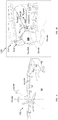
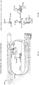
- Vehicle CS V xyz shown in FIG . 1A is a Cartesian representation of the principal axes of rotation of a vehicle 500 (herein exemplified by an aircraft) that is located in a reference world space 10 , which can be a physical or real reference world space, or a virtual (e.g., computer-generated) reference world space.
- a physical reference world space is different from a virtual reference world space in that the physical reference world space actually comprises a control station 510 , whereas the virtual reference world space may be used in a simulation environment and simulates or emulates that control station 510 is located within a selected reference world space.
- the virtual reference world space can be different from the physical space in which control station 510 is located in reality.
- V xyz is spatially fixed to vehicle 500 , so that an attitude of vehicle 500 may be expressed by the angles of the vehicle CS V xyz relative to a world coordinate system ( Wxyz ) of reference world space 10 .
- Non-limiting examples of control station 510 can include a cockpit (e.g., of a passenger plane, a combat aircraft, a vertical takeoff and landing (VTOL) aircraft, a tiltrotor aircraft, a transport aircraft, a fixed-wing aircraft, a rotary-wing aircraft, and/or a combined fixed/rotary-wing aircraft); a bridge of a watercraft (e.g., a passenger ship, a frigate, an aircraft carrier, a freighter); a driver cabin (e.g., of a car, bus, truck and/or armored fighting vehicle); a submarine control/command room; a vehicle control simulator (e.g., a flight simulator, a passenger car driving simulator); and/or any other vehicle command or control room, e.g., including for remote controlling of a vehicle, as outlined herein below in more detail.
- a cockpit e.g., of a passenger plane, a combat aircraft, a vertical takeoff and landing (VTOL) aircraft, a tiltrotor aircraft,
- embodiments disclosed herein may relate to aircrafts, this should by no means be construed limiting. Accordingly, embodiments disclosed herein may additionally or alternatively be employed in conjunction with vehicles including, for example, land-based vehicles such as, for instance, a passenger car, a motorcycle, a bicycle, a transport vehicle (e.g., a bus, truck, a rail-based transport vehicle, etc.), a watercraft, a submarine, a spaceship, a multipurpose vehicle such as a hovercraft, and/or the like.
- land-based vehicles such as, for instance, a passenger car, a motorcycle, a bicycle, a transport vehicle (e.g., a bus, truck, a rail-based transport vehicle, etc.), a watercraft, a submarine, a spaceship, a multipurpose vehicle such as a hovercraft, and/or the like.
- a control station may embody a remote control station for remotely controlling (e.g., piloting) a vehicle.
- a display device 1200 such as an HMD may be worn by a user (e.g., pilot) 600 .
- a “user” may herein also be referred to as a "pilot” of aircraft 500 ; and a “display device” may herein also be referred to as "HMD”.
- an HMD may be embodied by glasses and/or goggles (e.g., including night vision goggles) which are mounted on a helmet.
- an HMD may comprise glasses and/or goggles.
- Display device 1200 is configured to display information to pilot 600 to facilitate the piloting of aircraft 500 .
- An orientation of display device 1200 relative to the vehicle coordinate system Vxyz is herein exemplarily expressed by a display device or HMD coordinate system D x-roll , y-pitch , z-yaw ( D xyz ) that is defined as being spatially fixed to display device 1200 .
- display device coordinate system D xyz may be the principal axes of display device 1200 .
- both display device 1200 and user 600 can be carried by vehicle 500 and may be, for example, located in cockpit 510 .
- display device 1200 may move freely within vehicle 500 and still be operationally usable by user 600 .
- Display device 1200 may for example move freely in cockpit 510 , a freight space, a deck of a ship and/or in any area or location of vehicle 500 while, at the same time, be operationally usable by user 600 wearing display device 1200 as exemplified herein.
- Display device 1200 is configured to display one or more symbols 1400 conveying information to user 600 .
- display device 1200 may project symbols 1400 onto a symbology display area 1212 of a display component 1210 (e.g., a "see-through combiner" or a visor) which are then reflected towards user 600 .
- display device 1200 may allow user 600 to see through display device 1200 so that the one or more symbols 1400 are superimposed with the pilot's current field of view (CFOV) of the outside world.
- CFOV pilot's current field of view
- Additional or alternative display technologies may be employed including, for example, a flat substrate as a display, or a night vision goggles (NVG), while allowing the user to "see-through” the display.
- NVG night vision goggles
- the one or more symbols 1400 may be automatically and continuously displayed through placement and replacement.
- symbols 1400 may hereinafter be referred to in the singular as “symbol 1400” or the plural as “symbols 1400 ", depending on the context.
- display device 1200 is a see-through device, different positions on the display surface can represent different angles.
- Milliradians (mRAD) may for example be used as angular measurement units to indicate different positions on display device 1200 .
- An orientation of symbol 1400 relative to the display device coordinate system D xyz (and therefore relative to display device 1200 or the orientation of the user's head) is herein exemplarily expressed by a symbol coordinate system S x-roll , y-pitch , z-yaw or S xyz that is spatially fixed with symbol 1400 to be displayed by display device 1200 .
- symbol coordinate system S xyz can define three symbol principal axes of rotations that are orthogonal to each other.
- origin O of S xyz can be outside symbology display area 1212.
- aspects of embodiments are directed to the display of symbols 1400 relative to the user's or HMD wearer's 600 total field of view (TFOV).
- TFOV refers to the HMD wearer's view for a complete range of rotation and translation of the wearer's head
- the user's CFOV refers to what the HMD wearer or user can see at a given moment.
- a pilot's ability to control a vehicle may become compromised due to sensory mismatch, which may include motion sickness and spatial disorientation such as vertigo and, therefore, adversely affect the pilot's situational awareness.
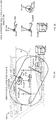
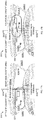
- FIGs. 2A and 2B schematically shows a scenario that may cause sensory mismatch.
- a non-conformal symbols 1420 herein exemplified as "IAS" (indicated airspeed), vertical altitude and speed scales 1420A-C, respectively, are fixed with respect to display device 1200.
- Further examples of non-conformal symbols may pertain to vital signs of user 600 , outside temperature; outside humidity; outside pressure; cabin pressure; fuel reserves; battery power; engine thrust; instrument functionality; and/or G-force on an aircraft.
- Display device 1200 is shown to roll through angle + ⁇ relative to the vehicle's roll axis V x-roll , and non-conformal symbol 1420 rolls along with display device 1200 to the same extent, namely through angle + ⁇ .
- the dashed lines indicate the initial position of display device 1200 and non-conformal symbol 1420 before rotation, and the continuous lines show final orientation after rotation. Accordingly, orientation of non-conformal symbol IAS is altered by angle + ⁇ relative to V x-rol l of cockpit 510 , possibly causing sensory mismatch. Roll orientation of the pilot's head relative to cockpit 510 may change many times during a comparatively short period of time, causing orientation of non-conformal symbol IAS to change relative to cockpit 510 equally often.
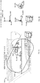
- FIGs. 3A and 3B schematically exemplify how the likelihood of sensory mismatch occurrences may be reduced, according to some embodiments.
- vertical altitude and speed scales 1420B1 and 1420B2 are not illustrated starting from FIGs. 3A and 3B , and the description below may refer to non-conformal IAS and/or any other non-formal symbol using alphanumeric designation " 1420 ".
- the roll orientation S x-roll of non-conformal symbol IAS is orientationally fixed with respect to the vehicle's roll axis V x-roll .
- display device 1200 rolls through angle + ⁇ relative to the vehicle's roll axis V x - roll
- the orientation of non-conformal symbol IAS remains unchanged with respect to the vehicle's roll axis V x-roll , thereby possibly reducing the likelihood of sensory mismatch.
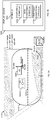
- a gaze tracking and display (GTAD) system 1000 is operable to determine an orientation and translational position of display device 1200 relative to control station (also: cockpit) 510, first remote control station 9510 and/or second remote control station 9511.
- control station also: cockpit
- Alphanumeric designations " 9510 " and " 9511 " concern remote control stations, which are discussed herein in more detail in conjunction with Figs. 11-13 .
- GTAD system 1000 can determine the CFOV that can be seen by pilot 600 through display component 1210 .
- the pilot's CFOV of the outside world can include, for example, a view of the aircraft's cockpit and/or a view of the exterior of the aircraft.
- a current view of the aircraft's exterior can be conveyed by displaying user 600 an image (or sequence of images) emulating a view of the exterior.
- the pilot may view an exterior of the aircraft via a stationary display device (not shown) that is positionally fixed with respect to cockpit 510 or a remote control station.
- symbol(s) 1400 can convey to user 600 a variety of information including, for example, the aircraft's pitch, azimuth, roll, velocity relative to ground, height, and flight direction.
- GTAD system 1000 comprises components and/or modules which are operable to implement a gaze tracker engine 1310 and a symbology rendering engine 1320, e.g., as outlined herein.
- gaze tracker engine 1310 and symbology rendering engine 1320 are operable to implement methods, processes and/or procedures relating to the display of one or more symbols 1400 to user 600 .
- a module may be a self-contained hardware and/or software component that interfaces with a larger system.
- a module may comprise a machine or machines executable instructions.
- a module may be embodied by a circuit and/or a controller programmed to cause the system to implement the method, process and/or operation as disclosed herein.
- a module may be implemented as a hardware circuit comprising, e.g., custom Very Large Scale Integrated (VLSI) circuits or gate arrays, an Application-specific integrated circuit (ASIC), off-the-shelf semiconductors such as logic chips, transistors, and/or other discrete components.
- VLSI Very Large Scale Integrated
- ASIC Application-specific integrated circuit
- a module may also be implemented in programmable hardware devices such as field programmable gate arrays, programmable array logic, programmable logic devices and/or the like.
- Gaze tracker engine 1310 may be operable to determine an estimate relating to a current position and orientation of display device 1200 relative to the cockpit of aircraft 500.
- Symbology rendering engine 1320 may be operable to cause display component 1210 to provide a video output of a symbol 1400 depending on the determined current position and orientation of display device 1200 . More specifically, a type and/or orientation and/or position of a display symbol 1400 displayed by display component 1210 at any given moment may depend on a current orientation and/or position of display device 1200 relative to the cockpit of aircraft 500 as determined, e.g., by gaze tracker engine 1310 .
- GTAD system 1000 comprises a gaze tracker subsystem 1100 that is, e.g., embedded in vehicle 500 or in a remote control station.
- Gaze tracker subsystem 1100 may comprise control station gaze tracking components 1120 .
- Control station gaze tracking components 1120 can be operatively coupled with display gaze tracking components 1220 of display device 1200 such to allow determining an estimate of a position and/or orientation of display device 1200 relative to control station 510 .
- Gaze tracker subsystem 1100 may be operable to determine the user's gaze based on a head pose of the user and/or based on the user's eye-gaze direction.
- control station gaze tracking components 1120 and display gaze tracking components 1220 for determining a head pose including, for example, optical, electromagnetic, inertial sensors (e.g., one or more accelerometers and/or gyroscopes), and/or sonic-based technologies.
- control station gaze tracking components 1120 may for example comprise alternating electric field generators (not shown) that are operable to produce an alternating electric field in the cockpit of aircraft 500 .
- Display gaze tracking components 1220 may for example include conductive coils (not shown) that are comprised in display device 1200 .
- Such conductive coils are configured to produce different voltages based on a current position and orientation of display device 1200 in the cockpit of aircraft 500 .
- gaze tracker engine 1310 can determine an estimate of the position and orientation of display device 1200 relative to the cockpit of aircraft 500 , and symbology rendering engine 1320 may cause display component 1210 to provide a video output of a symbol 1400 according to the determined instant current position and orientation estimate.
- various technologies may be employed by gaze tracker subsystem 1100 for determining the user's eye-gaze direction or point of gaze Px including, for example, camera-based and/or reflection-based eye-movement tracking.
- Devices and/or systems (not shown) employed for tracking the user's eye-gaze direction may be head- and/or vehicle-mounted.
- a position of symbology display area 1212 ( FIG. 2A ) changes according to a change in position of the head of pilot 600.
- a point of intersection of (an optionally tracked) eye-gaze direction Px with display component 1210 may change relative to the frame that defines the boundaries of symbology display area 1212 .
- Gaze tracker subsystem 1100 may comprise, in addition to control station gaze tracking components 1120 , a control station gaze tracking processor 1140 , a control station gaze tracking memory 1130 , a control station gaze tracking communication module 1150 , and a control station gaze tracking power unit 1160 for powering the various components and/or modules of control station gaze tracker subsystem 1100 .
- display device 1200 may comprise display gaze tracking components 1220 , display memory 1230 , display processor 1240 , display communication module 1250 , and display device power unit 1260 for powering the various components of display device 1200 .
- HMD wearer 600 may be located in vehicle 500 .
- separate hardware components such as processors and/or memories may be allocated for each component and/or module in GTAD system 1000 .
- processors and memories may be allocated to implement gaze tracker engine 1310 and symbology rendering engine 1320 .
- control station gaze tracking memory 1130 and to control station gaze tracking processor 1140 and to display memory 1230 and display processor 1240 for implementing gaze tracker engine 1310 , symbology rendering engine 1320 , and/or other functions of GTAD system 1000 , e.g., as outlined herein.
- GTAD system 1000 may communicate with each other over one or more communication buses (not shown), signal lines (not shown) and/or a network infrastructure 5000 .
- control station gaze tracking memory 1130 and/or display memory 1230 may include one or more types of computer-readable storage media including, for example, transactional memory and/or long-term storage memory facilities and may function as file storage, document storage, program storage, and/or as a working memory.
- control station gaze tracking memory 1130 and/or display memory 1230 may for example be in the form of a static random access memory (SRAM), dynamic random access memory (DRAM), read-only memory (ROM), cache and/or flash memory and include, for instance, temporally-based and/or non-temporally based instructions.
- SRAM static random access memory
- DRAM dynamic random access memory
- ROM read-only memory
- cache and/or flash memory include, for instance, temporally-based and/or non-temporally based instructions.
- control station gaze tracking memory 1130 and/or display memory 1230 may for example include a volatile or non-volatile computer storage medium, a hard disk drive, a solid state drive, a magnetic storage medium, a flash memory and/or other storage facility.
- a hardware memory facility may for example store a fixed information set (e.g., software code) including, but not limited to, a file, program, application, source code, object code, data, and/or the like.
- processor may encompass a controller.
- a processor such as, for example, control station gaze tracking processor 1140 and/or display processor 1240 may be implemented by various types of processor devices and/or processor architectures including, for example, embedded processors, communication processors, graphics processing unit (GPU)-accelerated computing, soft-core processors and/or general purpose processors.
- GPU graphics processing unit
- Control station gaze tracking communication module 1150 and/or display communication module 1250 may, for example, include I/O device drivers (not shown) and network interface drivers (not shown) for enabling the transmission and/or reception of data over network infrastructure 5000 , e.g., from gaze tracker subsystem 1100 to display device 1200 and vice versa.
- network infrastructure 5000 may, for example, operate on and/or implement various avionics Local Area Network (LAN) communication standards including, for example, Aeronautical Radio INC. (ARINC) 429, ARINC 629, MUX Bus 1553, Controller Area Network (CAN) BUS, and/or Avionics Full-Duplex Switched Ethernet (AFDX).
- LAN Local Area Network
- ARINC Aeronautical Radio INC.
- ARINC 629 ARINC 629
- MUX Bus 1553 Controller Area Network (CAN) BUS
- AFDX Avionics Full-Duplex Switched Ethernet
- Subsystem power unit 1160 and display device power unit 1260 may comprise an internal power supply.
- display device power unit 1260 may comprise an interface for allowing connection to an external power supply (e.g., from aircraft 500 ).
- Gaze tracker engine 1310 and/or symbology rendering engine 1320 may be implemented by any suitable device, fully or partially.
- implementations and/or processes and/or elements and/or functions of gaze tracker engine 1310 and/or symbology rendering engine 1320 may be implemented by control station gaze tracker subsystem 1100 , and/or by display device 1200 .
- control station gaze tracking memory 1130 and/or display memory 1230 may include instructions which, when executed e.g. by the control station gaze tracking processor 1140 and/or display processor 1240 , may cause the execution of a methods, processes and/or operations as disclosed herein.
- Gaze tracker engine 1310 and/or symbology rendering engine 1320 may operatively interface with vehicle instruments and process data relating to the vehicle instruments for generating the corresponding symbology to be displayed by display device 1200 .
- Gaze tracker engine 1310 and/or symbology rendering engine 1320 may operatively interface with vehicle instruments and process data relating to the vehicle instruments for generating the corresponding symbology to be displayed by display device 1200 .
- at least some or all symbology may be generated external to display device 1200 .
- communication between symbology rendering engine 1320 and display device 1200 may be mainly video.
- GTAD system 1000 is operable to allow selectively (also: controllably) spatially fixing the orientation of at least one symbol rotation axis ( S ⁇ ) of symbol coordinate system S xyz with a principal axis descriptive of an orientation of vehicle 500 .
- S ⁇ may be the symbol rotation axis S x - roll , which may be orientationally fixed with at least one principal axis (e.g., V x-roll ) of the vehicle coordinate system V xyz .
- At least one further principal symbol axis ( S ⁇ ) is correspondingly selectively spatially fixable either to at least one other principal axis of vehicle 500 or of the display device coordinate system D xyz
- the orientational fixation of symbol rotation axes S ⁇ and S ⁇ may be predetermined in GTAD system 1000 and/or occur "on-the-fly", e.g., during the piloting of aircraft 500 .
- a symbol may be descriptive of, or represent, a vehicle state vector. Such symbol may herein be referred to as "vehicle state vector symbol".
- a vehicle state vector symbol represents a state of the vehicle at a particular time instance.
- a vehicle state vector symbol can for example represent values of aircraft flight parameters such as the aircraft's flight path vector (FPV); and/or engine thrust direction and/or magnitude.
- FPV flight path vector
- a translational position of a vehicle state vector symbol may be adjusted in accordance with the values pertaining to the vehicle state vector.
- embodiments and examples pertaining to a vehicle state vector may be outlined with respect to an aircraft's FPV.
- a translational position of a symbol 1400 may be adjusted (e.g., translationally fixed) in accordance with a position of vehicle state vector on display device 1200 .
- the symbol's rotational orientation may not be adjusted in accordance in accordance with the position of the vehicle state vector (e.g., the FPV).
- the translational adjustment of symbol 1400 which can represent a vehicle state vector, may be predetermined in GTAD system 1000 and/or occur "on-the-fly", e.g., during the piloting of aircraft 500 .
- GTAD system 1000 may be operable to adjust the translational position of a vehicle state vector symbol in accordance with a change of translational position of display device 1200 in vehicle 500 and/or in accordance with a change in a parameter value described by the vehicle state vector.
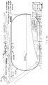
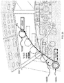
- Symbology display area 1212 shown in FIG. 5A exemplarily delineates the imaginary boundaries of a region in which computer-rendered symbols 1400 can be displayed to pilot 600 by display component 1210 . It is noted that symbology display area 1212 may encompass only a part or the entire area of display component 1210 .
- symbols 1400 may be classified to belong to one of the following categories: conformal symbols 1410 , non-conformal symbols 1420 , or partially conformal symbols 1430 .
- a symbol is considered to be "conformal” if the information that it conveys preserves a scale and/or orientation with respect to World Coordinate System Wxyz .
- Non-limiting examples of conformal symbols 1410 can include a display of an artificial or synthetic horizon 1410A , flight path vector (FPV) 1410B , symbol descriptive of an acquired target; symbol pointing on an incoming missing and/or the like. and/or the like.
- a symbol can be considered to be “non-conformal” if the information that it conveys does not or only partially preserves a scale and/or orientation with respect to Wxyz .
- Non-limiting examples of non-conformal symbols 1420 can include a display of the aircraft's fuel level and/or status, cockpit pressure, indicated air speed (IAS), and/or any other type of information describable by a scalar; ordinal; categorical; and/or interval parameter.
- IAS indicated air speed
- FIGs. 5C and 5D Additional reference is made to FIGs. 5C and 5D to elaborate on the differences between conformal and partial-conformal display of symbols.
- FIG. 5C schematically exemplifies a scenario in which azimuth bar 1430 is displayed in a conformal manner in a virtual HUD (VHUD) region 5100FL whose boundary is schematically delineated by broken lines and herein exemplified as matching the area of a front left ( FL ) window of control station 510 .
- the azimuth angle is measured in a straight virtual surface which is "tangential" to the earth's surface, optionally with the north pole as Zero azimuth, increasing clockwise relative thereto.
- azimuth bar 1430 comprises ticks or markers 1431 , and a pointer 1432 .
- Markers 1431 indicate the azimuth angle
- pointer 1432 is fixed to the aircraft's nose, so that azimuth bar 1430 virtually "slides” relative to pointer 1432 responsive to a change in the vehicle's azimuth angle.
- the distance between each two neighboring markers 1431 may indicate a change in predetermined azimuth angle (e.g., 5 degrees).
- Azimuth bar 1430 is schematically illustrated in FIG. 5C as being displayed in a conformal manner such that angular displacement is identical to displacement of the external visual scene.
- FIG. 5D schematically shows a scenario in which symbology display area 1212 is displaced (e.g., turned to the left), compared to the situation shown in FIG . 5C .
- the distance between markers 1431 is condensed.
- azimuth markers 1431 and pointer 1432 are shown in partial conformity with respect to the external visual scene.
- the distance between markers may be condensed to convey more information in the same amount of space (not shown). In either case, change in azimuth angle is reduced or scaled down compared to displacements of the external visual scene.
- attitude symbology may be displayed to the user in a partially conformal manner including, for example, the vehicle's pitch ladder.
- Additional examples of partially conformal symbols 1430 can include roll (also: bank) indication.
- a FPV may also be categorized as a partially conformal symbol.
- FIGs. 6A and 6B schematically showing a scenario in which, initially, the orientation of both display device rotation axes D xyz and Symbol rotation axes S xyz are aligned with the vehicle principal axes V xyz for all rotation axes x-roll, y-pitch and z-yaw .
- display device rotation axes D xyz may in some embodiments be considered to be principal axes of display device 1200 .
- symbol rotation axes S xyz may in some embodiments be considered to be principal axes of symbol 1400 , as if symbol 1400 was a rigid body.
- non-conformal symbol 1420 may be a real or imaginary rectangle and is shown in FIG. 6A to facilitate illustrating a roll angle or orientation of non-conformal symbol 1420 relative to vehicle CS Vxyz .
- the rectangular's long edge of IAS 1420 which in the current orientation shown in FIG. 6A is illustrated to be parallel to principal axis with V y - pitch , is considered to coincide with the principal axis S y - pitch .
- the rectangle's short edge of non-conformal symbol 1420 is considered to coincide with the principal axis S z - yaw ; and a direction which is normal to the rectangle and pointing in distal direction away from user 600 wearing display device 1200 and, hence, pointing in direction of the user's CFOV, is considered to coincide with S x-roll .
- GTAD system 1000 may be configured so that a change in azimuth angle of display device 1200 relative to Vxyz does not cause a change in the display of yaw orientation of non-conformal symbol 1420.
- FIG. 7A and 7B exemplify a scenario in which at least S z - yaw ( S ⁇ ) is spatially fixed with respect to V z - yaw .
- At least one further symbol rotation axis ( S ⁇ ) (e.g., S x-roll ) may be spatially fixed to either D x-roll or V x-rol l
- principal axis S y-pitch may be spatially fixed to either D y-pitch or V y-pitch .
- a relative displacement of non-conformal symbol 1420 with respect to symbology display area 1212 due to the spatial fixing of S z - yaw ( S ⁇ ) with respect to V z-yaw is schematically illustrated by arrow R1 .
- a position in which non-conformal symbol 1420 would be if S z - yaw ( S ⁇ ) was not fixed with respect to V z-yaw is schematically illustrated in FIG. 5A by the broken lines of rectangle 1420 .
- a positive yaw rotation is herein expressed by angle + ⁇ .
- Principal axis S x-roll may be spatially fixed to either D x-roll or V x -roll
- principal axis S y-pitch may be spatially fixed to either D y-pitch or V y-pitch .
- GTAD system 1000 may be configured so that at least a change in pitch orientation of display device 1200 does not cause a change in the display of pitch orientation of non-conformal symbol 1420 .
- FIGs. 8A and 8B exemplify such scenario in which at least S y-pitch (S ⁇ ) is spatially fixed with respect to V y-pitch .
- At least one further symbol rotation axis (e.g., symbol rotation axis S x-roll ) may be spatially fixed either with D x-roll or with V x-roll
- principal axis S z - yaw may be spatially fixed either with D z-yaw or with V z - yaw
- a relative displacement of non-conformal symbol 1420 with respect to symbology display area 1212 due to the spatial fixing of S y-pitch (S ⁇ ) with respect to V y-pitch is schematically illustrated by arrow R2 .
- a position in which non-conformal symbol 1420 would be if S y-pitch ( S ⁇ ) was not fixed with respect to V y-pitch is schematically illustrated in FIG. 8A by the broken lines of rectangle 1420 .
- a negative pitch rotation is herein expressed by angle - ⁇ .
- principal axis S x-roll may be spatially fixed to either D x-roll or V x-roll
- principal axis S z - yaw may be spatially fixed to either D z-yaw or V z - yaw .
- GTAD system may be configured so that at least roll orientation S x-roll ( S ⁇ ) of symbol coordinate system S xyz is spatially fixed with the principal x-roll axis Vx of vehicle 500 .
- at least the roll orientation of symbol 1400 may remain fixed with respect to V xyz , despite a change in a roll angle of display device 1200 relative to vehicle coordinate system V xyz by ⁇ .
- a relative displacement of non-conformal symbol 1420 with respect to symbology display area 1212 due to the spatial fixing of S x-roll ( S ⁇ ) with respect to V x-roll is schematically illustrated by broken rotation arrow M1.
- the principal pitch axis (also: S y-pitch ) of non-conformal symbol 1420 can be orientationally fixed either with the V y-pitch axis of vehicle principal axes V xyz or with D y-pitch axis of D xyz
- the principal yaw axis (also: S z-yaw ) of non-conformal symbol 1420 can be orientationally fixed either with the V z-yaw axis of vehicle principal axes V xyz or with D z-yaw axis of D xyz .
- FIGs. 10A and 10B schematically exemplify a tilted orientation for display device 1200 for a scenario in which principal axis S x-roll is spatially fixed relative to V x-roll , while both S y-pitch and S z - yaw are spatially fixed to D y-pitch and D z-yaw , respectively.
- the first row lists the vehicle's principal axes V x-roll , V y-pitch and V z-yaw , and rows 1 to 14 list various options for orientationally fixing principal axes of rotation S xyz of non-conformal symbol 1420 to axes V x-rol l , V y-pitch and V z - yaw .
- the options for translationally fixing of non-conformal symbol 1420 with respect to FPV are listed as well. It is noted that only pitch and yaw of non-conformal symbol 1420 may be translationally fixed with the FPV, but not the symbol's rotational orientation.
- a change in pitch of non-conformal symbol 1420 can be considered to be equivalent up/down movement, and a change in yaw of non-conformal symbol 1420 can be considered to be equivalent to a left/right movement on display device 1200 .
- V x-roll V y-pitch V z-yaw FPV Exemplified in Figures: 1. S x-roll N/A N/A N/A FIGs. 9A - 9B , and FIGs. 10A-10B 2. S x-roll S y-pitch N/A N/A Not shown 3. S x-roll S y-pitch S z-yaw N/A Not shown 4.
- N/A N/A S z - yaw N/A FIGs. 7A-7B 5.
- a remote control GTAD system 9000 may comprise one or more display devices which are located remotely from remote controllably vehicle 9500 in a location 9510.
- location 9510 may also be referred to as "remote control station 9510 " .
- Remote control GTAD system 9000 is operable to convey to a user 9600 located at remote control station 9510, via the one or more display devices, a digital image of an emulated view of the exterior of remote controllable vehicle 9500 from a perspective of remote controllable vehicle 9500.
- Coordinate system RC xyz is a Cartesian representation of the principal axes of remote control station 9510.
- Coordinate system V xzy defines an orientation of remote controllable vehicle 9500 with respect to World coordinate system W xyz .
- Coordinate system D(wearable) xyz (also: D(wr) xyz ) defines an orientation of external wearable display device 9200 (comprising a symbology display are 9212) with respect to remote control station 9510.
- external wearable display device 9200 may move freely in remote control station 9510.
- Symbol coordinate system S xyz defines an orientation of a symbol that is displayed to user 9600.
- the one or more display devices may include, in addition to external wearable display device 9200, a non-wearable, external display device 9700.
- Coordinate system D(ext) xyz defines an orientation of external wearable display device 9200 relative to a remote control station 9511.
- a remote control station (e.g, first remote control station 9510 or second remote control station 9511 ) is spatially fixed relative to world reference frame W xyz .
- orientation and/or position of a remote control station can change relative to world reference frame W xyz .
- a remote control station is comprised in another vehicle such as a ship, an aircraft, a truck, and/or the like.
- a remote control station can be mounted on a moving platform (not shown) which may comprise mounts (not shown), and which may be operable to controllably change the position and/or orientation of the remote control station such that an orientation of the remote control station is fixed with respect to an attitude of remote controllable vehicle 9500 . More specifically, the orientation of a remote control station and remote controllable vehicle 9500 relative to world reference frame W xyz may be synchronized with each other and (substantially) identical.
- external wearable display device 9200 may be spatially (e.g., orientationally) fixed with respect to the attitude of remote controllable vehicle 9500, while remote control station 9510 is spatially (e.g., orientationally) fixed with respect to world reference frame W xyz .
- both external wearable display device 9200 and the remote control station are either spatially (e.g., orientationally) fixed with respect to world reference frame W xyz or to remote controllable vehicle 9500 .
- a method for providing information to user 9600 for remote monitoring and/or remote controlling a vehicle 9500 that is located in a reference world space 10 via one or more display devices that are located remotely from the vehicle in a remote control station comprises providing a vehicle coordinate system ( V xyz ) that defines an attitude of the vehicle relative to a world coordinate system ( W xyz ) of the reference world space 10 ; conveying by the one or more display devices a digital image of an emulated view of the exterior of the vehicle from a perspective of the vehicle.
- the one or more display devices comprise at least, a head-mounted display device that is wearable by the pilot 600 .
- the method comprises providing a symbol coordinate system ( S xyz ) that is spatially associated with a symbol to be displayed on the head-mounted display device.
- the symbol coordinate system ( S xyz ) defines three symbol rotation axes that are orthogonal to each other.
- the method also comprises spatially fixing at least one of the symbol rotation axes ( S ⁇ ) to a principal axis of rotation of remote controllable vehicle 9500 .
- the method includes selectively spatially fixing at least one further symbol rotation axis ( S ⁇ ) to one of the following: at least one other principal axis of rotation of remote controllable vehicle 9500 ; and at least one principal axis of the head mounted display device coordinate system.
- a translational position of symbol 1400 that is displayed on display device 1200 may be adjusted according to the vehicle state vector.
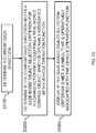
- a method for providing information to user 600 of vehicle 500 (or remote controllable vehicle 9500 ) via a display device 1200 (or wearable external display device 9200 ) that is worn by user 600 may comprise, in an embodiment, providing a principal axes of rotation coordinate system (V XYZ ) that defines a vehicle orientation relative to a world coordinate system (W xyz ) of the reference world space 10 (step 13100 ).
- V XYZ principal axes of rotation coordinate system
- W xyz world coordinate system
- the method further comprises providing at least one display device coordinate system ( D xyz ) that defines a display device orientation relative to the vehicle coordinate system, wherein display device 1200 is operable to visually display to user 600 at least one first symbol (step 13200 ).
- D xyz display device coordinate system
- the method comprises providing a symbol coordinate system ( S xyz ) that is spatially associated with the at least one first symbol to be displayed on display device 1200 and that defines three symbol rotation axes that are orthogonal to each other (step 13300 ).
- the method comprises spatially fixing at least one of the symbol rotation axes ( S ⁇ ) to one of a principal axis of rotation of V xyz , (step 13400 ). At least one further symbol rotation axis ( S ⁇ ) is correspondingly selectively spatially fixable to one of at least one other principal axis of rotation of V xyz ; and at least one principal axis of the display device coordinate system D xyz .
- GTAD system 1000 is configured such that orientationally fixing a symbol rotation axes to either a principal rotation axes of the vehicle or a rotation axis of the display device as described herein, can be accomplished without requiring installation and/or arrangement of dedicated markers and/or sensors in the control station and/or on or in the display device in order to provide a reference.
- the pilot's view of the outside world that can be seen through display device 1200 can include, for example, a view of the aircraft's cockpit 510 and/or a view of the exterior of the aircraft 500 (cf. for instance to FIG. 5A ).
- the view of the outside world may depend on the current orientation and position of display device 1200 relative to cockpit 510.
- the TFOV refers to the view for a complete range of rotation and translation in cockpit 510 by the user's 600 head wearing display device 1200.
- the user's 600 TFOV may be divided (e.g., classified by a classifier) into at least two cockpit viewing regions, e.g., as disclosed herein.
- a "region" of a TFOV may be defined in accordance with pilot's 600 gaze direction as determined by gaze tracker engine 1310 ( FIG. 4 ).
- a control station such as cockpit may be spatially divided into various viewing regions of the pilot's TFOV.
- the boundaries of various cockpit viewing regions may be defined in a (e.g., registration) procedure in which gaze directions are operatively associated with symbology rendering engine 1320 , so that information conveyed via display component 1210 may depend on the cockpit viewing region the pilot 600 is gazing at. It is noted that a hysteresis interval may also be applied for determining if gaze is directed towards one or another cockpit viewing region.
- the expression "conveying information”, as well as grammatical variations thereof, may not only refer to altering a displayed symbol as a result of the pilot's gaze direction, but also to making a computer-based decision regarding display or non-display of a symbol, e.g., as outlined herein below in more detail.
- a gaze direction of pilot 600 may be determined based on the orientation of display device 1200. Additionally or alternatively, a pilot's 600 gaze direction may be determined using an eye tracker (not shown), which may for example be comprised in display device 1200 .
- two cockpit viewing regions of a TFOV may optionally comprise one or more "VHUD regions" 5100, one or more "outside VHUD regions" 5200, and one or more "masked regions” 5300.
- VHUD region may be further subdivided into a conformal and non-conformal VHUD region (not shown).
- Conformal VHUD region may be defined such to allow the display of conformal, non-conformal and partially conformal symbology. In the non-conformal VHUD region, only non-conformal symbology may be displayed.
- non-conformal VHUD region may refer to viewing angles which cover areas of cockpit 510 which neither comprise instrumentation nor provide a view of the exterior of the vehicle.
- Such non-conformal VHUD region may herein exemplified by frame element 550 .
- GTAD system 1000 may be configured so that if gaze is directed towards VHUD region 5100 , symbols 1400 are displayed like on a "real" head-up display.
- GTAD system 1000 may be configured so that if gaze is directed towards outside VHUD regions 5200 , then at least one orientation and/or translational position of symbols 1400 is spatially fixed with respect to at least one of the axes D xyz of display component 1210 , instead of being spatially fixed with respect to the corresponding at least one of principal axes V xyz of vehicle 500 when gazing towards VHUD region 5100.
- At least one further symbol rotation axis ( S ⁇ ) that was before the transition spatially fixed with one of the principal axes V xyz may become spatially fixed with a corresponding or rotation axis of display D xyz .
- GTAD system 1000 may be configured so that when gaze is directed towards a masked region 5300, comparatively fewer and/or different, or no symbols 1400 may displayed by display component 1210.
- masked regions 5300 may spatially coincide with instrument panels of a control station 510 (e.g., of an aircraft's cockpit).
- masked region 5300 may virtually "cover” or mask all instruments of control station 510 .
- masked region 5300 may mask at least portions of a window of control station 510 .
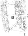
- FIG. 15 Additional reference is made to FIG. 15 .
- the terms "right” and “left” are used to describe a position in cockpit 510 with respect to an imaginary symmetry plane 5050 that lies in the plane spanned by V x-roll and V x-yaw , when gazing in direction of V x-roll .
- display device 1200 is considered to be positioned left of imaginary symmetry plane 5050 (when e.g., a pilot sitting in the left seat (not shown) of cockpit 510 )
- any gaze direction of pilot 600 that may substantially coincide with a forward-left cockpit window 5100FL may be defined, for the same display device 1200, as VHUD region 5100FL.
- any one of pilot's 600 gaze direction that may substantially intersect either with a forward-right cockpit window 5200FR, a right-side cockpit window 5200R, or with a left-side cockpit window 5200L, may correspondingly define outside VHUD regions 5200FR, 5200R and 5200L, respectively.
- any gaze direction that may intersect with critical instrument panels such as, for example, upper instrument panel 5300up and lower instrument panel 5300down may be correspondingly define masked regions 5300up and 5300down.
- a current gaze direction is herein illustrated by vector P x .
- gaze direction vector P x does not necessarily have to be normal to the inner or outer surface of display component 1210.
- the "inner" surface of display component 1210 is proximal, and the “outer” surface is distal to pilot 600 wearing display device 1200.
- gaze direction vector P x may be orientationally and translationally fixed with respect to display device 1200 so that P x can be considered to be spatially fixed with respect to D x .
- gaze direction vector P x may be orientationally and translationally fixed with respect to the pilot's eye-gaze direction in which case the gaze direction vector Px may not be normal to the surfaces of display component 1210.
- gaze tracker engine 1310 may determine that the current gaze direction vector P x is towards VHUD region 5100FL .
- Symbology rendering engine 1320 may, accordingly, cause symbol 1400 , to be displayed by display component 1210 .
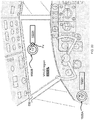
- gaze tracker engine 1310 may determine that another gaze direction vector P x of pilot 600 is towards lower masked region 5300down. Accordingly, symbology rendering engine 1320 may discontinue displaying symbol 1400 that was displayed while gazing towards VHUD region 5100FL . Such discontinuation of symbol display is in FIG. 16B schematically illustrated by a transition of continuous lines to broken lines for symbol 1400 .
- the display of one or more symbols may be discontinued while continuing the display of one or more other symbols.
- vertical altitude and speed scales also: columns
- 1420B1 and 1420B2 may still be displayed, e.g., in a roll-compensated manner which is exemplified in FIG. 3A ) when gazing towards a masked region (e.g., masked region 5300 down ).
- the type of symbol displayed to the pilot may change from one category to another when changing gaze from a VHUD region to a masked region, and vice versa.
- alternative symbols may be displayed instead of the discontinued symbol(s).
- the alternative symbols shown when gazing towards a masked region may for example provide an augmented view of the real-world control objects of the masked region (e.g., masked region 5300down ) .
- the alternative symbols may for example complement information provided by and/or enhance visibility of the real-world control objects of a masked region.
- the alternative symbols may, for instance, provide the pilot with a visual feedback (e.g., a digital symbol superimposed on the real-life control object) to indicate towards which control object he is gazing at.
- a value that is associated with a control object may be displayed to the pilot as long as the pilot is gazing at it.
- a symbol descriptive of a radio volume may be displayed by display device 1200 as long as the pilot is gazing at the respective real-life volume control of the control panel.
- one or more orientations of S xyz of symbol 1400 may become spatially fixed with respect to D xyz of display component 1210 instead of being spatially fixed to a principal axis of rotation of V xyz when the wearer is gazing towards VHUD region 5100.
- the type of symbol displayed to the pilot may change from one category to another when changing gaze from a VHUD region to an outside-VHUD region, and vice versa.
- information e.g., aircraft pitch
- a conformal symbol 1410 pilot 600 when gazing towards VHUD region 5100FL may be conveyed to the pilot by a non-conformal symbol 1420 when the pilot is gazing towards outside VHUD display region 5200FR ( FIG. 17D ).
- an arrow Q may be displayed to indicate the pilot a direction towards he/she should traverse his/her gaze direction for viewing VHUD region 5100FL again.
- At least one orientation may again become spatially fixed with respect to a principal axis Vxyz, instead of being spatially fixed with respect to D xyz when gazing towards the outside VHUD region 5200FR.
- a translational position of symbol 1400 may again become spatially fixed with respect to the vehicle state vector instead of being spatially fixed with respect to D xyz when gazing towards the outside VHUD region 5200FR.
- information that is conveyed to pilot 600 gazing towards an outside VHUD region 5200 may be conveyed in a conformal manner when pilot 600 is gazing again towards VHUD region 5100.
- gaze tracker engine 1310 and/or symbology rendering engine 1320 are operable to determine the position of a symbol 1400 relative to a boundary of a cockpit viewing region.
- the translational position of a symbol may be altered depending on the gaze direction.
- symbol 1400 can represent a vehicle state vector, such as the FPV. In the discussion that follows, such symbol may referred to as "direction symbol”. A translational position of direction symbol 1400 may be adjusted in accordance change of the vehicle state vector.
- direction symbol 1400 may be displayed in a first or regular display mode. Otherwise stated, in the regular display mode, direction symbol 1400 is displayed in manner which conforms to the value of the direction parameter. However, if the symbol representing the vehicle state vector cannot be displayed (also: is not displayable) in a directionally conformable manner within the given field of view (e.g. when a direction parameter of the vehicle state vector would require display of the symbol outside the field of view of display device 1200 ), then the symbol may be displayed in a ghosted display mode.
- FPV 1410B as the vehicle state vector symbol, it may be displayed in one of a regular and ghosted mode depending on the amount or magnitude of (angular) drift of aircraft 500 ( FIG. 1A ) and the orientation of display device 1200.
- the position of FPV 1410B relative to artificial horizon 1410A can indicate whether the aircraft is ascending or descending. Since the FPV may, in some embodiments, be displayed in one of a regular and ghosted mode, the FPV may be categorized as a partially-conformal symbol.
- FIG. 18A schematically illustrates FPV 1410B a scenario in which it is displayed in the regular display mode. That is, the distance between FPV 1410B and artificial horizon 1410A corresponds to the rate of ascent of the aircraft.
- the magnitude of the aircraft's ascent or descent may exceed a certain displaying threshold such that FPV 1410B cannot be displayed in a translationally conformal manner within the boundaries of VHUD region 5100.
- FPV 1410 may be displayed in a second, "ghosted" mode, which is schematically illustrated in FIG. 18B by the dashed lines of ghosted FPV 1410B'.
- the ghosted display is to indicate to pilot 600 that the position of ghosted FPV 1410B' is not where it actually should be.
- the position where FPV 1410B actually should be displayed if it was translationally conformal, is shown in FIG. 18B to be within masked region 5300up.
- aspects of embodiments may concern a method that comprises selectively displaying the vehicle state vector symbol relating to a directional parameter value in one of the following display modes: in a first, regular display mode, as long as the vehicle state vector symbol can be displayed to the user by the display device in a directionally conformable manner within a given field of view; and in a second, ghosted display mode, if the vehicle state vector symbol cannot be displayed by the display device in a directionally conformable manner within the given field of view.
- the vehicle state vector is displayed differently than in the regular display mode.
- line thickness, line style, line color and/or the like may be different in the regular and the ghosted display mode.
- the regular display mode of FPV 1410B is represented in FIG. 18A by its continuous lines
- the ghosted display mode of FPV 1410B is represented in FIG. 18B by its broken lines.
- a translational position of symbol 1400 (e.g., translational position of non-conformal symbol 1420 ) as displayed by display device 1200 may be adjusted (e.g., translationally positioned on symbology display area 1212 ) in accordance with a position of a vehicle state vector.
- arrow R symbol schematically illustrates traversing non-conformal symbol 1420 in accordance with the traversing of FPV 1410B in direction of R FPV , which may be due to a change in one or more of the values associated with FPV 1410B and/or a change in the position and/or orientation of symbology display area 1212 .
- the origin O of symbol coordinate system Sxyz may be translationally fixed with respect to, e.g., the position of FPV 1410B .
- the roll orientation of non-conformal symbol 1420 may be spatially fixed with respect to the roll orientation of the vehicle.
- the gaze direction of user 600 may be continuously tracked. While the gaze is tracked, it may be determined if a gaze-based object selection criterion is met. If the gaze-based object selection criterion is met, the user is provided with information (e.g., a feedback) indicating that the gaze-based object selection criterion is met.
- information e.g., a feedback
- an object selection criterion defines the conditions for selecting a certain object by the pilot.
- An object selection criterion may be based on input parameter values such as the the pilot's gaze, gesture, utterance, and/or based on any other suitable physical action.
- a gesture tracking system (not shown) may track gestures (e.g., finger and/or hand gesturing by the user) and operable to recognize an object the pilot wants to select.
- object selection may be utterance-based (e.g., through a suitable voice command).
- An object selection criterion may pertain to a variety of different user inputs concurrently. For example, for an object to be selected, the conditions pertaining to both gaze-based and physical engagement inputs may have to be met simultaneously or according to a certain predetermined sequence.
- a gaze-based object selection criterion may for example pertain to one or more thresholds of a difference value between a current gaze direction and a reference gaze direction towards the gaze-selectable object. It is noted that the term "reference direction" as used herein may refer to a single reference direction or to reference directions that are within a certain range.
- a gaze-based object selection criterion may for example be met if the difference value is below a threshold, and the gaze-based object selection criterion may not be met if the difference value is equal or above the threshold. In another example, the gaze-based object selection criterion may be met if the difference value is equal or below a threshold, and the gaze-based object selection criterion may not be met if the difference value is above the threshold.
- a "gaze-based object selection criterion" may take into account, inter alia, a hysteresis interval between two different thresholds, depending on the direction of change of the HMD wearer's gaze direction.
- the hysteresis interval may for example be defined by a selection threshold that is lower than a non-selection threshold, e.g., as outlined herein below.
- a hysteresis interval may be applicable to additional or alternative object selection inputs.
- GTAD system 1000 may be operable to determine if the user's current gaze direction meets a gaze-based object selection criterion for allowing initiating an action associated with a gaze-selectable object.
- a gaze direction of an HMD's wearer may be considered to be directed at a gaze-selectable object if a "gaze-based object engagement criterion" is met.
- the gaze direction is considered as not be selectably directed at the gaze-selectable object.
- GTAD system 1000 may for example generate (e.g., graphically render) and display to pilot 600 a symbol that is operatively associated with a real-world control object (e.g., controls or control elements) of control station (e.g., cockpit) 510, if the object selection criterion is met.
- a real-world control object e.g., controls or control elements
- control station e.g., cockpit
- a gaze-based object selection criterion may for example be met if an imaginary gaze vector P x representing the user's gaze direction intersects, e.g., for a certain dwell time, with a selectable virtual object which is operatively associated with a real world physical object.
- a selectable virtual object may be operatively associated with a real world physical object and/or a vehicle operation function such as, for instance, an aircraft control element.
- a "real world physical object" may include a hardware element and/or a graphical symbol displayed by a hardware element, e.g., in a masked region.
- a selectable virtual object may be defined as a virtual plane having boundaries and/or contours that correspond to and virtually "overlay" the gaze-selectable object.
- the operable association between a vehicle operation function and a virtual object may be such so that responsive to a gaze-based selection of the selectable virtual object, user 600 is provided with information relating to the vehicle operation function, e.g., as outlined herein below in more detail.
- Methods, processes and/or procedures of gaze-based selection of a real-world control object and the display of a symbol or virtual object that is operatively associated with the vehicle operation function controllable by real-world control object may herein be referred as "actionably acquiring a real-world control object", as well as grammatical variations thereof.
- actionably object a control element may first require “selection of the control element".
- the selection of a real-world control object may provide the pilot with an indication that, for example, the gaze direction intersects with selectable object, yet that at least one validation input has to be provided for actionable acquisition, such that the corresponding virtual object is displayed in VHUD region 5100, or to spatially lock the virtual object with the gaze direction.
- Such validation input may for example comprise a physical action (e.g., push button actuation) during the dwell time of gaze direction on the selectable object, a gesture (e.g., a hand and/or finger gesture-based input), utterance of a command input, and/or the like.
- Validation may be confirmed by responsively providing pilot 600 with a sensory feedback (e.g., audible feedback).
- a sensory feedback e.g., audible feedback
- Non-limiting examples of real-world selectable objects can include a physical object outside the control station, e.g., as seen through a window and/or conveyed graphically via a display comprised in control station 510 ; a graphical object (e.g., symbol) displayed to the user, e.g., via an HMD worn by the user; and/or a physical and/or real-world control object comprised in control station 510 such as a control element.
- a physical object outside the control station e.g., as seen through a window and/or conveyed graphically via a display comprised in control station 510 ; a graphical object (e.g., symbol) displayed to the user, e.g., via an HMD worn by the user; and/or a physical and/or real-world control object comprised in control station 510 such as a control element.
- Control elements comprised in cockpit/control station 510 may be employed for controlling various systems of aircraft 500 ( FIG. 1A ) including, for example, the aircraft's engines, fuel pump system, flight control hydraulics, electrical system, oxygen system, navigation system, air-conditioning system, LAN communication system, wing heating/anti-ice controls, window heating controls, radio communication system, door controls, and/or the in-flight entertainment system. It is noted that, exemplarily, only a selection of the controls may be actionably acquirable by the pilot. Optionally, only non-critical real-life control objects may be actionably acquirable by the pilot. Non-limiting examples of non-critical real-control objects may include, for example, radio frequency knobs; volume knobs; metric selection switches; environmental conditioning controls (e.g., temperature, humidity, lighting, digital panel displays); and/or the like.
- Cockpit control elements can include, for example, switches, dials, knobs, push buttons, levers, indicators, wheels and/or handles. Controls may require a multiple-step actuation sequence to prevent accidental actuation of the control.
- an actionable acquisition of the selectable (real-world control) object may automatically initiate an automated action of generating a symbol which is operatively associated with the selected real-world object and/or the corresponding vehicle operation function, e.g., as outlined herein below in more detail.
- an actionable engagement criterion for actionably engaging a virtual object (also: a symbol) which may be associated with the selected object and/or displayed to the user.
- the gaze-based object selection criterion and actionable engagement criterion may be identical.
- a virtual object or symbol may be actionably engageable by a gaze-based input and/or using gesture-based, utterance-based and/or any other suitable physical action.
- a gesture tracking system may track gestures (e.g., finger and/or hand gesturing by the user) and operable to recognize that a symbol is actionably engaged.
- the actionable acquisition of real-world control objects is herein exemplified with respect to a real-world control object herein referenced by alphanumeric designation " 1600A ".
- a (real-world) control object 1600A is exemplified as a rotary control knob which is employed for changing an operational scalar value (e.g., a radio communication frequency), which in the present state is set to "10200".
- an operational scalar value e.g., a radio communication frequency
- a control such as a "rotary control knob” may be one-handed operable by the user.
- a rotary control knob may be embodied by a consolidated control handle push button assembly.
- a symbol may be displayed indicating pilot 600 that gaze-based selection criterion is met.
- the symbol may be spatially associated with the real-world control object.
- the displayed symbol may represent virtual control object 1600B.
- Virtual control object 1600B may for example be mixed with or superimposed onto real-world rotary control knob 1600A to convey to pilot 600 a combined imagery of the real-world rotary control knob 1600A and virtual control object 1600B.
- virtual control object 1600B is shown as dashed lines extending along the contour edges of real-world rotary control knob 1600A.
- a symbol coordinate system S xyz is spatially associated with a virtual control object 1600B, which may represent a virtual rotary control knob.
- virtual control object 1600B and virtual control knob 1600B may herein be used interchangeably.
- Virtual control knob 1600B can include the scalar display that is associated therewith.
- the virtual control objects may be displayed on symbology display area 1212 (cf. for instance to FIG. 5A ) in a spatially fixed relationship with the pilot's gaze direction (e.g., spatially fixed with the orientation and position of display device 1200 or with the pilot's eye-gaze direction).
- a spatially fixed relationship with the pilot's gaze direction e.g., spatially fixed with the orientation and position of display device 1200 or with the pilot's eye-gaze direction.
- illustration of symbology display area 1212 is omitted from FIGs. 19-22 .
- the spatial fixing of virtual control objects (e.g., virtual rotary control knob 1600B) with respect to the pilot's gaze direction may in an embodiment be accomplished as schematically shown in FIGs.
- the pilot's gaze direction may always intersect with a geometric center of a virtual control objects such as rotary control knob 1600B .
- a virtual control object such as virtual rotary control knob 1600B may be displayed to pilot 600 at some predetermined or dynamically adjustable position relative to the pilot's current gaze direction.
- an actionable acquired virtual control object that is displayed in accordance with the pilot's gaze direction vector P x may be "handed over" to become, at least partially, translationally and/or orientationally fixed with respect to another reference coordinate system.
- display of the virtual control objects may be confined within VHUD region 5100.
- a virtual control object e.g., control object 1600B
- At least one first selected symbol rotation axis ( S ⁇ ) of the virtual control object becomes orientationally fixed, correspondingly, to at least one principle axis of the vehicle.
- At least one further symbol rotation axis ( S ⁇ ) is selectively spatially fixable to one of: at least one at least one further principle axis of the vehicle; and at least one axis of the display device coordinate system.
- the translational position of a symbol may be displayed in accordance with an operational state of aircraft 500.
- a procedure of handing over an actionably acquired virtual control object may be initiated responsive to receiving a suitable input at GTAD system 1000 meeting an object handoff criterion.
- the object handoff criterion may for example relate to the pilot's gaze direction towards VHUD region 5100FL and/or a physical action performed by the pilot.
- the object handoff criterion may be met if pilot 600 gazes at a certain area of VHUD region 5100FL for a predetermined dwell time to designate the area as a "locked-in area" (not shown).
- display of the virtual object may then be spatially fixed with respect to a geometric center of the locked-in area.
- display of the virtual object may be spatially fixed with respect to a virtual intersection point between a current gaze direction P x with VHUD region 5100FL at the time the object handoff criterion is met.
- the virtual intersection point may be displayed to pilot 600 in the form of a specific (e.g. pointer) symbol (not shown).
- a virtual control object e.g., virtual rotary control knob 1600B may be displayed immediately at a predetermined position of VHUD region 5100FL, without requiring pilot 600 to change his/her gaze direction towards VHUD region 5100FL for spatially associating the virtual control object with VHUD region 5100FL.
- virtual rotary control knob 1600B may be substantially immediately displayed in a spatially fixed manner relative to VHUD region 5100FL after the actionable acquisition of the real-world control object is completed.
- the virtual symbol after the virtual symbol is handed off (e.g., positionally confined within VHUD region 5100 ), its display may change in accordance with an input provided at the real-world control object with which the virtual symbol is operatively coupled with.
- information conveyed by the virtual control object to user 600 is selectable based on an input provided by the user via the real-world control object. For example, as shown schematically in FIGs. 21 and 22 , imparting a rotary motion on real-world rotary control knob 1600A may cause GTAD system 1000 to animate a corresponding rotary motion of virtual rotary control knob 1600B.
- the computerized display of information associated with real-world control object 1600B may be altered in accordance with the rotary input provided at real-world control object 1600A , e.g., by pilot 600 .
- rotating real-world rotary control knob 1600A in clockwise direction T1 may cause animation of virtual rotary control knob 1600B by GTAD system 1000 to simulate a corresponding rotary motion thereof.
- the value associated with real-world control knob may change accordingly.
- a change in a displayed value responsive to imparting a clockwise rotary motion T1 on real-world rotary control knob 1600A is herein exemplified by a change from "10200" in FIG. 20 to "10199" in FIG. 21 .
- a change in a displayed value responsive to imparting a counterclockwise rotary motion T2 on real-world rotary control knob 1600A is herein exemplified by a change from "10200" in FIG. 20 to "10201" in FIG. 22 .
- a virtual symbol that is operatively associated with an actionably acquired real-world control object may be operatively selectable or engagable if, e.g., a corresponding gaze-based virtual object selection criterion is met.
- a state of a vehicle operation function e.g., radio frequency or volume level
- a state of a vehicle operation function associated with the virtual object may be changed, e.g., without requiring performing a physical action on the acquired real-world control object.
- actionably engaging virtual object 1600B to change for example, display of "10200” to “10199” on VHUD region 5100FL can cause a corresponding change in the value (also from “10200” to "10199") displaye by the real-world display associated with real-world control knob 1600A .
- actionably acquirable real-world may include rotary control knobs which can change values or states (e.g., "ON”/ "OFF”) irrespective of the knobs' initial orientation.
- only rotary control knobs may be actionably acquirable by the pilot which can change values or states (e.g., "ON”/ "OFF”) irrespective of the knobs' initial orientation.
- the same virtual object can be selectively operatively associated with different real-world control objects.
- virtual rotary control knob 1600B is exemplified as being operatively associated with real-world rotating control knob 1600A (e.g., for selecting radio frequencies).
- Virtual object 1600B may subsequently be operatively associated by the pilot with another real-world rotating knob (not shown) which may for example be employed to select the cabin's temperature.
- a series of suitable inputs that collectively meet a "symbol association-change criterion" may be predefined and/or provided by the pilot.
- the pilot may change the operable association of a virtual object from one real-world control object to another real-world control object.
- a virtual object that is operatively associated with an actionably acquired real-world control object may be selectively displayed in a conformal or a non-conformal manner.
- the display of a virtual object that is operatively associated with an actionably acquired real-world control object may be discontinued, e.g., responsive to receiving a corresponding input from the pilot.
- Generating and displaying to the pilot a symbol that is operatively associated with a real-world control object may involve a method that comprises determining a current gaze direction or tracking a pilot's gaze direction (step 23100 ) .
- the method may then further comprise determining if the current gaze direction meets a gaze-based object selection criterion (step 23200 ) for actionably acquiring a real-world control object.
- the method may additionally comprise displaying, if the gaze-based object selection criterion is met, a symbol that is operatively associated with the real-world control object (step 23300 ).
- a gaze-based object criterion selection may met if and as long the wearer's gaze direction intersects with a first area of a virtual selectable object, defining the selection threshold.
- the gaze-based object selection criterion stops to be met if the current gaze direction seizes to intersect with a second area of the virtual selectable object which is enlarged compared to the first area of the virtual selectable object and which defines the non-selection threshold.
- a gaze-based object selection criterion may be met if and as long as the difference value (e.g., the angle) between the current and a virtual gaze direction towards the object drops below, or becomes equal or drops below the selection threshold.
- the gaze-based object selection criterion seizes to be met if the difference value exceeds, or becomes equal to or exceeds the non-selection threshold which is higher than the selection threshold.
- virtual gaze direction refers to a possible future gaze direction of pilot 600 (cf. Fig. 1B ), as opposed to a current or actual gaze direction of pilot 600 (cf. Fig. 1B ) at a particular time instance, as determined by GTAD system 1000.
- the selection threshold may be set to be lower than the non-selection threshold by a magnitude of 0.05 radians or less, by 0.04 radians or less, by 0.03 radians or less, by 0.02 radians or less, or by 0.01 radians or less.
- a plurality of (e.g., non-conformal) symbols 1400 may be displayed in VHUD region 5100. At least two of the plurality of symbols 1400 may be different from one another. That is, the at least two symbols may, for example, pertain to different operating parameters of vehicle 500 , display device 1200 and/or vital signs of user 600 . Accordingly, the at least two symbols may have different functionalities and pertain, for example, to different vehicle operation functions.
- the number of non-conformal symbols 1400 to be displayed in VHUD region 5100 and their corresponding functionality may be customizable, e.g., per each user, vehicle and/or display device.
- the non-conformal symbols 1400 are automatically displayed, at least once display device 1200 is worn by user 600 and operationally coupled with vehicle 500 .
- pilot-initiated actionable instrument acquisition as described with respect to FIGs. 19-22 may not be required in order for the non-conformal symbols 1400 to be displayed in VHUD region 5100 in symbology display area 1212 .
- the symbols 1400 may be gaze-, gesture, utterance-based and/or otherwise selectable and/or actionably engageable by user 600 , if a selection criterion and/or actionably engagement criterion is met, respectively.
- symbols 1400 may be selectable through a physical action (e.g., gesture-based selection, gaze-based selection, utterance-based selection, push button and/or control knob actuation) by user 600 .
- a non-conformal symbol 1420 for instance may, for example, first preselected by scrolling sequentially from left to right (or vice versa) over non-conformal symbols 1420 , which may be stationary with respect to VHUD region 5100.
- the scrolling may be accomplished in a one-handed manner by user 600 using, e.g., a rotary control knob (not shown) which moves a "selector", exemplified herein by dashed box, over the stationary non-conformal symbols 1420 .
- the selector may be stationary with respect to VHUD region 5100 , and the symbols 1420 may be moved relative to the selector. While FIGs. 24A and 24B exemplify embodiments with respect to non-conformal symbols 1420 , this should not be construed in a limiting manner.
- a symbol 1400 such as a non-conformal symbol 1420 may be highlighted, colored and/or otherwise indicated as "selected”.
- the selected non-conformal symbol 1420 may then be actionably engaged, e.g., using a push button (not shown), using gaze-based selection, gesture-based selection, and/or any other physical action.
- a corresponding command input may be provided to vehicle 500.
- the display of the symbol may change accordingly.
- non-conformal symbol 1420 may concern the activation ("ON”) or deactivation ("OFF”) of an air-conditioning (also: "A/C”) system.
- ON activation
- OFF deactivation
- the A/C system (non-conformal symbol 1420C2 ) is shown as turned to "OFF” and actionably engaged (schematically indicated by dashed box and the bold fonts), such to be turned “ON” ( FIG. 24B ).
- the synthetic vision system (SVS) is shown to be unselected, whereas in FIG . 24B , the SVS is shown as being actionably engaged, schematically illustrated by the bold fonts and the dashed box around non-conformal symbol 1420C3 .
- the "12XA" symbol (non-conformal symbol 1420C1) is shown as being unselected.
- the same control (not shown) can be used to actionably engage a selected non-conformal symbols 1420A-C .
- the same real-world control knob 1600A schematically shown in FIG. 22 may be used to actionably engage any one of non-conformal symbols 1420A-C selected by pilot 600 .
- display device 1200 is adapted to receive an input from user 600 for selecting and/or controlling various systems of vehicle 500 . Accordingly, display device 1200 may be modified from a device which merely conveys information to user 600 , to a device which is can receive inputs from user 600 .
- a method of controlling a vehicle operation function may include displaying, by display device 1200 worn by user 600 , a plurality of selectable non-conformal symbols which are associated with respective plurality of vehicle operation functions (step 25100 ).
- the method of controlling a vehicle operation function may further include selecting a symbol of the plurality of symbols for allowing actionably engaging the selected symbol by user 600 .
- a symbol may be selected if the object selection criterion is met.
- Any digital computer system, module and/or engine exemplified herein can be configured or otherwise programmed to implement a method disclosed herein, and to the extent that the system, module and/or engine is configured to implement such a method, it is within the scope of the disclosure as solely defined by the appended claims.
- the system, module and/or engine are programmed to perform particular functions pursuant to computer readable and executable instructions from program software that implements a method disclosed herein, it in effect becomes a special purpose computer particular to embodiments of the method disclosed herein.
- the methods and/or processes disclosed herein may be implemented as a computer program product that may be tangibly embodied in an information carrier including, for example, in a non-transitory tangible computer-readable and/or non-transitory tangible machine-readable storage device.
- the computer program product may directly loadable into an internal memory of a digital computer, comprising software code portions for performing the methods and/or processes as disclosed herein.
- a computer readable signal medium may include a propagated data signal with computer readable program code embodied therein, for example, in baseband or as part of a carrier wave. Such a propagated signal may take any of a variety of forms, including, but not limited to, electro-magnetic, optical, or any suitable combination thereof.
- a computer readable signal medium may be any computer readable medium that is not a non-transitory computer or machine-readable storage device and that can communicate, propagate, or transport a program for use by or in connection with apparatuses, systems, platforms, methods, operations and/or processes discussed herein.
- non-transitory computer-readable storage device and “non-transitory machine-readable storage device” encompasses distribution media, intermediate storage media, execution memory of a computer, and any other medium or device capable of storing for later reading by a computer program implementing embodiments of a method disclosed herein.
- a computer program product can be deployed to be executed on one computer or on multiple computers at one site or distributed across multiple sites and interconnected by one or more communication networks.
- These computer readable and executable instructions may be provided to a processor of a general purpose computer, special purpose computer, or other programmable data processing apparatus to produce a machine, such that the instructions, which execute via the processor of the computer or other programmable data processing apparatus, create means for implementing the functions/acts specified in the flowchart and/or block diagram block or blocks.
- These computer readable and executable program instructions may also be stored in a computer readable storage medium that can direct a computer, a programmable data processing apparatus, and/or other devices to function in a particular manner, such that the computer readable storage medium having instructions stored therein comprises an article of manufacture including instructions which implement aspects of the function/act specified in the flowchart and/or block diagram block or blocks.
- the computer readable and executable instructions may also be loaded onto a computer, other programmable data processing apparatus, or other device to cause a series of operational steps to be performed on the computer, other programmable apparatus or other device to produce a computer implemented process, such that the instructions which execute on the computer, other programmable apparatus, or other device implement the functions/acts specified in the flowchart and/or block diagram block or blocks.
- Coupled with means indirectly or directly “coupled with”.
- the method may include is not limited to those diagrams or to the corresponding descriptions.
- the method may include additional or even fewer processes or operations in comparison to what is described in the figures.
- embodiments of the method are not necessarily limited to the chronological order as illustrated and described herein.
- Discussions herein utilizing terms such as, for example, “processing”, “computing”, “calculating”, “determining”, “establishing”, “analyzing”, “checking”, “estimating”, “deriving”, “selecting”, “inferring” or the like, may refer to operation(s) and/or process(es) of a computer, a computing platform, a computing system, or other electronic computing device, that manipulate and/or transform data represented as physical (e.g., electronic) quantities within the computer's registers and/or memories into other data similarly represented as physical quantities within the computer's registers and/or memories or other information storage medium that may store instructions to perform operations and/or processes.
- the term determining may, where applicable, also refer to "heuristically determining”.
- each of the verbs, "comprise” “include” and “have”, and conjugates thereof, are used to indicate that the object or objects of the verb are not necessarily a complete listing of components, elements or parts of the subject or subjects of the verb.
- a machine e.g., a processor
- the machine may include components, parts, or aspects (e.g., software) that enable the machine to perform a particular task. In some embodiments, the machine may perform this task during operation.
- a task is described as being done “in order to” establish a target result (e.g., in order to apply a plurality of electromagnetic field patterns to the object), then, at least in some embodiments, carrying out the task may accomplish the target result.
- range format is merely for convenience and brevity and should not be construed as an inflexible limitation on the scope of the embodiments. Accordingly, the description of a range should be considered to have specifically disclosed all the possible subranges as well as individual numerical values within that range. For example, description of a range such as from 1 to 6 should be considered to have specifically disclosed subranges such as from 1 to 3, from 1 to 4, from 1 to 5, from 2 to 4, from 2 to 6, from 3 to 6 etc., as well as individual numbers within that range, for example, 1, 2, 3, 4, 5, and 6. This applies regardless of the breadth of the range.
Landscapes
- Engineering & Computer Science (AREA)
- Physics & Mathematics (AREA)
- General Physics & Mathematics (AREA)
- Theoretical Computer Science (AREA)
- General Engineering & Computer Science (AREA)
- Human Computer Interaction (AREA)
- Radar, Positioning & Navigation (AREA)
- Remote Sensing (AREA)
- Combustion & Propulsion (AREA)
- Chemical & Material Sciences (AREA)
- Transportation (AREA)
- Mechanical Engineering (AREA)
- Aviation & Aerospace Engineering (AREA)
- Optics & Photonics (AREA)
- Computer Hardware Design (AREA)
- User Interface Of Digital Computer (AREA)
- Instrument Panels (AREA)
Claims (14)
- Procédé de fourniture d'informations, à un utilisateur (600) d'un véhicule (500), par l'intermédiaire d'un dispositif d'affichage (1200) qui est porté par l'utilisateur (600), le procédé comprenant les étapes ci-dessous consistant à :fournir un système de coordonnées de véhicule (Vxyz ) représentant les axes de rotation principaux du véhicule (500) pour définir une orientation de véhicule par rapport à un système de coordonnées universel (Wxyz ) d'un espace de référence mondial (10) ;fournir au moins un système de coordonnées de dispositif d'affichage (Dxyz ) qui définit une orientation de dispositif d'affichage par rapport au système de coordonnées de véhicule (Vxyz ), dans lequel le dispositif d'affichage (1200) est exploitable pour afficher visuellement à l'utilisateur (600) au moins un premier symbole (1400) ; etfournir un système de coordonnées de symbole (Sxyz ) qui est fixé spatialement avec ledit au moins un premier symbole (1400) à afficher sur le dispositif d'affichage (1200) et qui définit trois axes de rotation de symbole qui sont mutuellement orthogonaux ; etafficher ledit au moins un premier symbole (1400) ;caractérisé par l'étape ci-dessous consistant à :
fixer spatialement au moins l'un des axes de rotation de symbole (Sα ) à un axe de rotation principal de véhicule décrivant une orientation de véhicule (500) ; etdans lequel au moins un axe de rotation de symbole supplémentaire (Sβ ) peut être sélectivement fixé spatialement de manière correspondante à l'un parmi :au moins un autre axe de rotation principal du véhicule (500) ; etau moins un axe de rotation d'affichage du système de coordonnées de dispositif d'affichage (Dxyz). - Procédé selon la revendication 1, comprenant l'étape consistant à ajuster par translation une position dudit au moins un premier symbole affiché (1400) conformément à un vecteur d'état de véhicule, et dans lequel, par exemple, le vecteur d'état de véhicule se rapporte à un ou plusieurs des éléments suivants : un vecteur de trajectoire de vol ; et une direction de poussée de moteur et/ou une grandeur s'y rapportant.
- Procédé selon la revendication 2, comprenant l'étape consistant à afficher sélectivement un symbole dudit au moins un premier symbole (1400) qui représente le vecteur d'état de véhicule, dans l'un des modes d'affichage suivants :dans un premier mode d'affichage « classique », pour autant que le symbole représentant le vecteur d'état de véhicule peut être affiché à l'utilisateur (600) par le dispositif d'affichage (1200) d'une manière conforme à la direction dans un champ de vision donné ; etdans un second mode d'affichage « fantôme », si le symbole représentant le vecteur d'état de véhicule ne peut pas être affiché parle dispositif d'affichage (1200) d'une manière conforme à la direction dans le champ de vision donné.
- Procédé selon l'une quelconque des revendications précédentes, dans lequel l'étape de fourniture du système de coordonnées de symbole (Sxyz ) sur le dispositif d'affichage (1200) est exploitable dans toutes les orientations du système de coordonnées de symbole (Sxyz ) par rapport au système de coordonnées de véhicule (Vxyz ) ;dans lequel, par exemple, ledit au moins un des axes de rotation de symbole (Sα ) est une orientation de roulis qui est fixée spatialement, de manière correspondante, à l'orientation de roulis du système de coordonnées de véhicule (Vxyz ) ; etdans lequel ledit au moins un axe de rotation de symbole supplémentaire (Sβ ) est une orientation de tangage ou de lacet du système de coordonnées de symbole (Sxyz ) qui est fixée spatialement, de manière correspondante, à une orientation de tangage ou de lacet du système de coordonnées (Dxyz ) de dispositif d'affichage (1200) par rapport au système de coordonnées de véhicule (Vxyz ).
- Procédé selon l'une quelconque des revendications précédentes, comprenant en outre l'étape ci-dessous consistant à :
fournir un système de coordonnées de symbole de pointeur (Pxyz ) qui est associé spatialement à un symbole de pointeur à afficher sur le dispositif d'affichage (1200) et qui définit au moins deux axes de translation de symbole de pointeur (y-z) qui sont mutuellement orthogonaux. - Procédé selon la revendication 5, comprenant en outre les étapes ci-dessous consistant à :déterminer une première direction de regard en cours de l'utilisateur ; etafficher, sur le dispositif d'affichage, le symbole de pointeur simultanément audit au moins un premier symbole, dans lequel le symbole de pointeur indique la première direction de regard en cours de l'utilisateur.
- Procédé selon l'une quelconque des revendications précédentes, dans lequel ledit au moins un premier symbole affiché (1400) comprend un objet d'interface d'utilisateur (600) qui peut être engagé de manière sélective et actionnable par l'utilisateur (600).
- Procédé selon l'une quelconque des revendications 6 et 7, comprenant en outre les étapes ci-dessous consistant à :suivre le regard de l'utilisateur (600) ;déterminer si un critère de sélection d'objet basé sur le regard est satisfait ; etsi le critère de sélection d'objet basé sur le regard est satisfait, fournir, à l'utilisateur (600), des informations indiquant que le critère de sélection d'objet basé sur le regard est satisfait.
- Procédé selon la revendication 8, comprenant en outre l'étape ci-dessous consistant à :déterminer si un critère d'engagement actionnable est satisfait pour engager de manière actionnable un objet virtuel (1600B) qui est associé à l'objet d'interface d'utilisateur sélectionné.
- Procédé selon la revendication 9, dans lequel le critère de sélection fait référence à l'un quelconque des éléments suivants :un temps de maintien de la première direction de regard en cours dans un intervalle prédéterminé ; et/ouune action physique mise en œuvre par l'utilisateur (600).
- Procédé selon la revendication 5, comprenant les étapes ci-dessous consistant à :déterminer une deuxième direction de regard en cours de l'utilisateur (600) ;déterminer une deuxième valeur de différence entre la deuxième direction de regard en cours et au moins une direction de regard virtuelle ; etsi la deuxième valeur de différence dépasse une deuxième valeur de seuil de différence, fixer spatialement ledit au moins un axe de rotation de symbole supplémentaire (Sβ ) du système de coordonnées de symbole (Sxyz ) au système de coordonnées de dispositif d'affichage (Dxyz ) ; etpar exemple, comprenant en outre l'étape ci-dessous consistant à :
fixer spatialement ledit au moins un des axes de rotation de symbole (Sα ) au système de coordonnées de dispositif d'affichage (Dxyz ) ; etpar exemple, comprenant en outre l'étape ci-dessous consistant à :
afficher au moins un second symbole en correspondance avec et à la place dudit au moins un premier symbole (1400) ; etpar exemple, comprenant les étapes ci-dessous consistant à :déterminer une troisième valeur de différence entre une troisième direction de regard en cours et ladite au moins une direction de regard virtuelle ; etsi la troisième valeur de différence est inférieure à une troisième valeur de seuil de différence :
fixer spatialement au moins l'un des axes de rotation de symbole (Sα ) à au moins l'un des axes du système de coordonnées de véhicule (Vxyz ) pour afficher ledit au moins un premier symbole (1400). - Système (1000) d'affichage et de suivi du regard (GTAD) exploitable de manière à fournir des informations à un utilisateur (600) d'un véhicule (500) par l'intermédiaire d'un dispositif d'affichage (1200) qui est porté par l'utilisateur (600), le système comprenant :un ou plusieurs processeurs ; etune ou plusieurs mémoires stockant des parties de code logiciel exécutables par ledit un ou lesdits plusieurs processeurs pour amener le système GTAD (1000) à mettre en œuvre les étapes ci-dessous consistant à :fournir un système de coordonnées de véhicule (Vxyz ) qui définit une orientation de véhicule par rapport à un système de coordonnées universel (Wxyz ) d'un espace de référence mondial (10) ;fournir au moins un système de coordonnées de dispositif d'affichage (Dxyz ) qui définit une orientation de dispositif d'affichage par rapport au système de coordonnées de véhicule, dans lequel le dispositif d'affichage (1200) est exploitable pour afficher visuellement à l'utilisateur (600) au moins un premier symbole (1400) ; etfournir un système de coordonnées de symbole (Sxyz ) qui est fixé spatialement avec ledit au moins un premier symbole (1400) à afficher sur le dispositif d'affichage (1200) et qui définit trois axes de rotation de symbole qui sont mutuellement orthogonaux ; etcaractérisé par l'étape ci-dessous consistant à :fixer spatialement, au cours de l'affichage dudit au moins un premier symbole (1400), au moins l'un des axes de rotation de symbole (Sα ) à un axe de rotation principal de véhicule décrivant une orientation du véhicule (500), et dans lequel, au cours de l'affichage dudit au moins un premier symbole, au moins un axe de rotation de symbole supplémentaire (Sβ ) peut être sélectivement fixé spatialement de manière correspondante à l'un parmi :au moins un autre axe de rotation principal du véhicule ; etau moins un axe de rotation d'affichage du système de coordonnées de dispositif d'affichage (Dxyz ).
- Produit-programme informatique exploitable de manière à fournir des informations à un utilisateur (600) d'un véhicule (500) par l'intermédiaire d'un dispositif d'affichage (1200) qui est porté par l'utilisateur (600), le produit-programme informatique comprenant un support de stockage tangible non transitoire et/ou un support de stockage transitoire pouvant être lu(s) par un ou plusieurs circuits de traitement, et stockant des instructions destinées à être exécutées par ledit un ou lesdits plusieurs circuits de traitement en vue de mettre en œuvre un procédé comprenant les étapes ci-dessous consistant à :fournir un système de coordonnées de véhicule (Vxyz ) qui définit une orientation de véhicule par rapport à un système de coordonnées universel (Wxyz ) d'un espace de référence mondial (10) ;fournir un système de coordonnées de dispositif d'affichage (Dxyz ) qui définit une orientation de dispositif d'affichage par rapport au système de coordonnées de véhicule, dans lequel le dispositif d'affichage est exploitable pour afficher visuellement à l'utilisateur au moins un premier symbole (1400) ; etfournir un système de coordonnées de symbole (Sxyz ) qui est fixé spatialement avec au moins un premier symbole à afficher sur le dispositif d'affichage et qui définit trois axes de rotation de symbole qui sont mutuellement orthogonaux ; etafficher ledit au moins un premier symbole (1400) ;caractérisé par l'étape ci-dessous consistant à :fixer spatialement au moins l'un des axes de rotation de symbole (Sα ) à un axe de rotation principal de véhicule décrivant une orientation du véhicule ; etdans lequel au moins un axe de rotation de symbole supplémentaire (Sβ ) peut être sélectivement fixé spatialement de manière correspondante à l'un parmi :au moins un autre axe de rotation principal du véhicule (500) ; etau moins un axe de rotation d'affichage du système de coordonnées de dispositif d'affichage (Dxyz ).
- Système (1000) d'affichage et de suivi du regard (GTAD) exploitable de manière à fournir des informations à un utilisateur d'un véhicule par l'intermédiaire d'un dispositif d'affichage qui est porté par l'utilisateur, le système GTAD comprenant :un sous-système de suivi de regard (1100) d'une station de commande destinée à commander un véhicule, le sous-système de suivi du regard comprenant des composants d'outil de suivi de regard de station ;un dispositif d'affichage portable (1200) comprenant des composants de suivi de regard d'affichage ;un moteur de suivi de regard (1310) destiné à suivre le regard de l'utilisateur portant le dispositif d'affichage portable, dans lequel le regard de l'utilisateur est suivi sur la base d'informations fournies par le sous-système de suivi de regard et le dispositif d'affichage portable ; etun moteur de rendu de symbologie (1320) pour occasionner l'affichage d'au moins un premier symbole à l'utilisateur, par l'intermédiaire du dispositif d'affichage portable ;caractérisé en ce qu'un système de coordonnées de symbole (Sxyz ) est fixé spatialement avec ledit au moins un premier symbole et définit trois axes de rotation de symbole qui sont mutuellement orthogonaux ;dans lequel, au cours de l'affichage dudit au moins un premier symbole, et du suivi du regard de l'utilisateur, au moins l'un des axes de rotation de symbole (Sα ) est fixé spatialement par le moteur de rendu de symbologie à un axe de rotation principal de véhicule décrivant une orientation du véhicule (500), et dans lequel au moins un axe de rotation de symbole supplémentaire (Sβ ) peut être fixé spatialement de manière correspondante et sélective, par le moteur de rendu de symbologie, à l'un parmi :
au moins un autre axe de rotation principal du véhicule ; et au moins un axe de rotation d'affichage d'un système de coordonnées de dispositif d'affichage (Dxyz ).
Applications Claiming Priority (2)
| Application Number | Priority Date | Filing Date | Title |
|---|---|---|---|
| IL25205617A IL252056A (en) | 2017-05-01 | 2017-05-01 | Head-up display device, system and method |
| PCT/IL2018/050337 WO2018203320A1 (fr) | 2017-05-01 | 2018-03-24 | Dispositif visiocasque, système et procédé correspondants |
Publications (3)
| Publication Number | Publication Date |
|---|---|
| EP3414616A1 EP3414616A1 (fr) | 2018-12-19 |
| EP3414616A4 EP3414616A4 (fr) | 2019-02-27 |
| EP3414616B1 true EP3414616B1 (fr) | 2021-12-08 |
Family
ID=62045939
Family Applications (1)
| Application Number | Title | Priority Date | Filing Date |
|---|---|---|---|
| EP18737795.7A Active EP3414616B1 (fr) | 2017-05-01 | 2018-03-24 | Dispositif visiocasque, système et procédé correspondants |
Country Status (4)
| Country | Link |
|---|---|
| US (2) | US10586514B2 (fr) |
| EP (1) | EP3414616B1 (fr) |
| IL (1) | IL252056A (fr) |
| WO (1) | WO2018203320A1 (fr) |
Families Citing this family (27)
| Publication number | Priority date | Publication date | Assignee | Title |
|---|---|---|---|---|
| US10726625B2 (en) | 2015-01-28 | 2020-07-28 | CCP hf. | Method and system for improving the transmission and processing of data regarding a multi-user virtual environment |
| US10725297B2 (en) | 2015-01-28 | 2020-07-28 | CCP hf. | Method and system for implementing a virtual representation of a physical environment using a virtual reality environment |
| DE112016007015T5 (de) * | 2016-07-29 | 2019-03-21 | Mitsubishi Electric Corporation | Anzeigevorrichtung, anzeigesteuervorrichtung und anzeigesteuerverfahren |
| US10552497B2 (en) | 2016-08-16 | 2020-02-04 | International Business Machines Corporation | Unbiasing search results |
| FR3068481B1 (fr) * | 2017-06-29 | 2019-07-26 | Airbus Operations (S.A.S.) | Systeme et procede d'affichage pour un aeronef |
| US20190057180A1 (en) * | 2017-08-18 | 2019-02-21 | International Business Machines Corporation | System and method for design optimization using augmented reality |
| FR3072479B1 (fr) * | 2017-10-13 | 2022-06-10 | Airbus Operations Sas | Methode de visualisation synthetique d'une scene vue a partir d'un aeronef et systeme de vision synthetique pour mettre en œuvre une telle methode |
| CN108499104B (zh) | 2018-04-17 | 2022-04-15 | 腾讯科技(深圳)有限公司 | 虚拟场景中的方位显示方法、装置、电子装置及介质 |
| US11887495B2 (en) * | 2018-04-27 | 2024-01-30 | Red Six Aerospace Inc. | Augmented reality for vehicle operations |
| US11869388B2 (en) | 2018-04-27 | 2024-01-09 | Red Six Aerospace Inc. | Augmented reality for vehicle operations |
| US11436932B2 (en) * | 2018-04-27 | 2022-09-06 | Red Six Aerospace Inc. | Methods and systems to allow real pilots in real aircraft using augmented and virtual reality to meet in a virtual piece of airspace |
| US11508255B2 (en) | 2018-04-27 | 2022-11-22 | Red Six Aerospace Inc. | Methods, systems, apparatuses and devices for facilitating provisioning of a virtual experience |
| JP2021140195A (ja) * | 2018-05-31 | 2021-09-16 | ソニーグループ株式会社 | 情報処理装置、情報処理方法およびプログラム |
| FR3086400B1 (fr) * | 2018-09-26 | 2020-09-04 | Thales Sa | Systeme d'affichage tete haute, procede d'affichage et produit programme d'ordinateur associes |
| FR3089643A1 (fr) * | 2018-12-05 | 2020-06-12 | Airbus Operations (S.A.S.) | Cockpit d’aéronef et procédé d’affichage dans un cockpit d’aéronef. |
| CN111316217B (zh) * | 2019-04-12 | 2024-05-14 | 深圳市大疆创新科技有限公司 | 遥控可移动平台的控制方法、设备及计算机可读存储介质 |
| US11675324B2 (en) * | 2019-09-19 | 2023-06-13 | Bao Tran | Air transportation systems and methods |
| KR102349566B1 (ko) * | 2019-11-26 | 2022-01-11 | 한국전자기술연구원 | 비행 시뮬레이터를 위한 시선추적 데이터 및 훈련 시나리오 기반 공간정위 상실 탐지 시스템 |
| DE102019220055A1 (de) * | 2019-12-18 | 2021-06-24 | Robert Bosch Gmbh | Verfahren zum Reduzieren von Kinetose |
| US11830147B2 (en) * | 2020-05-28 | 2023-11-28 | Comcast Cable Communications, Llc | Methods and systems for anchoring objects in augmented or virtual reality |
| US11710216B2 (en) * | 2020-07-14 | 2023-07-25 | Gm Cruise Holdings Llc | Adaptive adjustments to visual media to reduce motion sickness |
| GB2602954B (en) * | 2020-08-21 | 2024-09-18 | Hill Group Tech Limited | Aircraft flight control |
| US20230005224A1 (en) * | 2021-07-01 | 2023-01-05 | Lenovo (Singapore) Pte. Ltd. | Presenting real world view during virtual reality presentation |
| EP4423740A1 (fr) * | 2021-10-27 | 2024-09-04 | BAE SYSTEMS plc | Système et procédé de symbologie coordonnée dans un système de réalité augmentée |
| US12008681B2 (en) * | 2022-04-07 | 2024-06-11 | Gm Technology Operations Llc | Systems and methods for testing vehicle systems |
| DE102023117959A1 (de) | 2023-07-07 | 2025-01-09 | Audi Aktiengesellschaft | Steuervorrichtung und Verfahren zum Erzeugen eines adaptierbaren künstlichen Horizonts |
| US12248144B1 (en) * | 2023-11-07 | 2025-03-11 | Honeywell International Inc. | Display system and method for reducing motion sickness |
Family Cites Families (52)
| Publication number | Priority date | Publication date | Assignee | Title |
|---|---|---|---|---|
| US4305057A (en) * | 1979-07-19 | 1981-12-08 | Mcdonnell Douglas Corporation | Concave quadratic aircraft attitude reference display system |
| US7180476B1 (en) | 1999-06-30 | 2007-02-20 | The Boeing Company | Exterior aircraft vision system using a helmet-mounted display |
| IL138831A (en) | 2000-10-03 | 2007-07-24 | Rafael Advanced Defense Sys | An information system is operated by Mabat |
| US6497649B2 (en) * | 2001-01-21 | 2002-12-24 | University Of Washington | Alleviating motion, simulator, and virtual environmental sickness by presenting visual scene components matched to inner ear vestibular sensations |
| US7774075B2 (en) * | 2002-11-06 | 2010-08-10 | Lin Julius J Y | Audio-visual three-dimensional input/output |
| US7128705B2 (en) * | 2002-11-26 | 2006-10-31 | Artis Llc | Motion-coupled visual environment for prevention or reduction of motion sickness and simulator/virtual environment sickness |
| JP2006047997A (ja) * | 2004-06-30 | 2006-02-16 | Canon Inc | 変調回路、駆動回路および出力方法 |
| US7722526B2 (en) * | 2004-07-16 | 2010-05-25 | Samuel Kim | System, method and apparatus for preventing motion sickness |
| DE102005061211B4 (de) * | 2004-12-22 | 2023-04-06 | Abb Schweiz Ag | Verfahren zum Erzeugen einer Mensch-Maschine-Benutzer-Oberfläche |
| WO2007105792A1 (fr) * | 2006-03-15 | 2007-09-20 | Omron Corporation | Dispositif et procede de surveillance, dispositif et procede de commande, et programme |
| US7383129B1 (en) | 2006-09-07 | 2008-06-03 | Itt Manufacturing Enterprises, Inc. | Method and system for geo-referencing and visualization of detected contaminants |
| US8416152B2 (en) | 2008-06-11 | 2013-04-09 | Honeywell International Inc. | Method and system for operating a near-to-eye display |
| US8120857B2 (en) | 2008-10-15 | 2012-02-21 | Gentex Corporation | Apparatus and method for mounting and calibrating a helmet-mounted display |
| US8362973B2 (en) | 2009-05-19 | 2013-01-29 | Honeywell International Inc. | Systems, apparatus and fast methods for aligning images to external markers in near-to-eye display systems |
| WO2011073682A1 (fr) * | 2009-12-17 | 2011-06-23 | Bae Systems Plc | Procédé d'alignement d'un système d'affichage monté sur casque |
| US20110193725A1 (en) | 2010-02-11 | 2011-08-11 | Honeywell International Inc. | Methods and systems for displaying a symbol representative of an aircraft in flight |
| US8690750B2 (en) * | 2010-05-14 | 2014-04-08 | Wesley W. O. Krueger | System and method for measuring and minimizing the effects of vertigo, motion sickness, motion intolerance, and/or spatial disorientation |
| US8531394B2 (en) | 2010-07-23 | 2013-09-10 | Gregory A. Maltz | Unitized, vision-controlled, wireless eyeglasses transceiver |
| JP5853331B2 (ja) * | 2011-03-11 | 2016-02-09 | 株式会社ブイ・テクノロジー | レーザ照射装置及びそれを使用した液晶表示パネルの輝点修正方法 |
| US9727132B2 (en) | 2011-07-01 | 2017-08-08 | Microsoft Technology Licensing, Llc | Multi-visor: managing applications in augmented reality environments |
| US9183807B2 (en) | 2011-12-07 | 2015-11-10 | Microsoft Technology Licensing, Llc | Displaying virtual data as printed content |
| US10013053B2 (en) | 2012-01-04 | 2018-07-03 | Tobii Ab | System for gaze interaction |
| US9024844B2 (en) | 2012-01-25 | 2015-05-05 | Microsoft Technology Licensing, Llc | Recognition of image on external display |
| US9035878B1 (en) | 2012-02-29 | 2015-05-19 | Google Inc. | Input system |
| US9519640B2 (en) | 2012-05-04 | 2016-12-13 | Microsoft Technology Licensing, Llc | Intelligent translations in personal see through display |
| US9696547B2 (en) | 2012-06-25 | 2017-07-04 | Microsoft Technology Licensing, Llc | Mixed reality system learned input and functions |
| FR2995092B1 (fr) * | 2012-08-31 | 2015-11-13 | Thales Sa | Systeme d'assistance a la tenue du vol stationnaire d'un helicoptere |
| US9886703B2 (en) * | 2012-11-08 | 2018-02-06 | xAd, Inc. | System and method for estimating mobile device locations |
| KR101878376B1 (ko) | 2012-11-14 | 2018-07-16 | 한국전자통신연구원 | 시선 기반의 제어 장치 및 그것의 기기 제어 방법 |
| JP6094190B2 (ja) | 2012-12-10 | 2017-03-15 | ソニー株式会社 | 情報処理装置および記録媒体 |
| KR101417470B1 (ko) * | 2012-12-12 | 2014-07-08 | 현대자동차주식회사 | 응시 대상 확인 장치 및 방법 |
| US9791921B2 (en) | 2013-02-19 | 2017-10-17 | Microsoft Technology Licensing, Llc | Context-aware augmented reality object commands |
| US20140240349A1 (en) * | 2013-02-22 | 2014-08-28 | Nokia Corporation | Method and apparatus for presenting task-related objects in an augmented reality display |
| FR3003049B1 (fr) | 2013-03-08 | 2015-04-10 | Thales Sa | Systeme de visualisation de casque comportant des moyens visuels d'interaction avec la symbologie affichee |
| FR3004817B1 (fr) | 2013-04-19 | 2015-05-15 | Thales Sa | Systeme de visualisation hybride affichant des informations en superposition sur l exterieur |
| IL226701A (en) | 2013-06-03 | 2017-07-31 | Itl Optronics Ltd | Platform Composite Device Control System and Method |
| US9710130B2 (en) | 2013-06-12 | 2017-07-18 | Microsoft Technology Licensing, Llc | User focus controlled directional user input |
| EP2843507A1 (fr) | 2013-08-26 | 2015-03-04 | Thomson Licensing | Procédé d'affichage par l'intermédiaire d'un dispositif monté sur la tête |
| GB2533520B (en) * | 2013-08-27 | 2021-02-10 | Auckland Uniservices Ltd | Gaze-controlled interface method and system |
| US9244539B2 (en) | 2014-01-07 | 2016-01-26 | Microsoft Technology Licensing, Llc | Target positioning with gaze tracking |
| US9201578B2 (en) | 2014-01-23 | 2015-12-01 | Microsoft Technology Licensing, Llc | Gaze swipe selection |
| US9437159B2 (en) | 2014-01-25 | 2016-09-06 | Sony Interactive Entertainment America Llc | Environmental interrupt in a head-mounted display and utilization of non field of view real estate |
| US9804753B2 (en) | 2014-03-20 | 2017-10-31 | Microsoft Technology Licensing, Llc | Selection using eye gaze evaluation over time |
| US9244280B1 (en) * | 2014-03-25 | 2016-01-26 | Rockwell Collins, Inc. | Near eye display system and method for display enhancement or redundancy |
| FR3020688B1 (fr) | 2014-04-30 | 2016-05-06 | Thales Sa | Systeme de visualisation de tete comportant des moyens de selections de cap et procede de selection associe |
| JP2016031439A (ja) | 2014-07-28 | 2016-03-07 | ソニー株式会社 | 情報処理装置及び情報処理方法、コンピューター・プログラム、並びに画像表示システム |
| KR20160015972A (ko) | 2014-08-01 | 2016-02-15 | 엘지전자 주식회사 | 웨어러블 디바이스 및 그 제어 방법 |
| US9489739B2 (en) | 2014-08-13 | 2016-11-08 | Empire Technology Development Llc | Scene analysis for improved eye tracking |
| GB2529683A (en) | 2014-08-29 | 2016-03-02 | Bae Systems Plc | Image display |
| KR101655818B1 (ko) * | 2014-12-11 | 2016-09-08 | 현대자동차주식회사 | 웨어러블 글래스, 그 제어 방법 및 차량 제어 시스템 |
| WO2017004580A1 (fr) | 2015-07-01 | 2017-01-05 | Schradin Aaron | Dispositif d'entrée pour siège à commande de mouvement |
| US20170235361A1 (en) * | 2016-01-20 | 2017-08-17 | Panasonic Automotive Systems Company Of America, Division Of Panasonic Corporation Of North America | Interaction based on capturing user intent via eye gaze |
-
2017
- 2017-05-01 IL IL25205617A patent/IL252056A/en active IP Right Grant
-
2018
- 2018-03-24 EP EP18737795.7A patent/EP3414616B1/fr active Active
- 2018-03-24 WO PCT/IL2018/050337 patent/WO2018203320A1/fr not_active Ceased
- 2018-07-18 US US16/038,336 patent/US10586514B2/en active Active
-
2019
- 2019-12-04 US US16/703,191 patent/US11004425B2/en active Active
Non-Patent Citations (1)
| Title |
|---|
| None * |
Also Published As
| Publication number | Publication date |
|---|---|
| US20200118527A1 (en) | 2020-04-16 |
| US20180366090A1 (en) | 2018-12-20 |
| US10586514B2 (en) | 2020-03-10 |
| US11004425B2 (en) | 2021-05-11 |
| IL252056A0 (en) | 2017-07-31 |
| IL252056A (en) | 2018-04-30 |
| EP3414616A4 (fr) | 2019-02-27 |
| WO2018203320A1 (fr) | 2018-11-08 |
| EP3414616A1 (fr) | 2018-12-19 |
Similar Documents
| Publication | Publication Date | Title |
|---|---|---|
| US11004425B2 (en) | Head mounted display device, system and method | |
| US10018847B2 (en) | Methods of vestibulo-ocular reflex correction in display systems | |
| US11760503B2 (en) | Augmented reality system for pilot and passengers | |
| US20240199224A1 (en) | Movable vehicle control interface | |
| US10254544B1 (en) | Head tracking accuracy and reducing latency in dynamic environments | |
| EP2124088B1 (fr) | Procédés pour l'exploitation de systèmes avioniques basés sur les gestes de l'utilisateur | |
| US9244649B2 (en) | Piloting assistance system and an aircraft | |
| US20170096237A1 (en) | Tactile and peripheral vision combined modality hover drift cueing | |
| EP2668646A1 (fr) | Système de commande de point de vue 3d pour l'avionique | |
| CN107487449B (zh) | 用于飞行器的显示系统和方法 | |
| CN107010237A (zh) | 用于在hud上显示fov边界的系统和方法 | |
| US11048079B2 (en) | Method and system for display and interaction embedded in a cockpit | |
| CN108319274A (zh) | 一种无人飞行器位置的图形显示方法 | |
| ES2957292T3 (es) | Aparato y método para definir e interactuar con regiones de un área operativa | |
| US20140055323A1 (en) | Visualisation system, notably for an aircraft, with a transparent screen and with peripheral symbology | |
| Newman et al. | Helmet-mounted display design guide | |
| US10969589B2 (en) | Head up display system, associated display system and computer program product | |
| US20200192468A1 (en) | Display system and method for an aircraft | |
| CN107014397A (zh) | 飞行器的头部观察系统中显示“姿态指引指示符”的方法 | |
| WO2026009068A1 (fr) | Systèmes et procédés d'alignement de transfert | |
| WO2025259633A1 (fr) | Cabine d'aéronef à voilure fixe, à écoulement laminaire et à traînée réduite | |
| US9643732B2 (en) | Aircraft attitude indicator device | |
| Lif et al. | Perceptual momentum for design of multimodal displays |
Legal Events
| Date | Code | Title | Description |
|---|---|---|---|
| STAA | Information on the status of an ep patent application or granted ep patent |
Free format text: STATUS: UNKNOWN |
|
| STAA | Information on the status of an ep patent application or granted ep patent |
Free format text: STATUS: THE INTERNATIONAL PUBLICATION HAS BEEN MADE |
|
| PUAI | Public reference made under article 153(3) epc to a published international application that has entered the european phase |
Free format text: ORIGINAL CODE: 0009012 |
|
| STAA | Information on the status of an ep patent application or granted ep patent |
Free format text: STATUS: REQUEST FOR EXAMINATION WAS MADE |
|
| 17P | Request for examination filed |
Effective date: 20180719 |
|
| AK | Designated contracting states |
Kind code of ref document: A1 Designated state(s): AL AT BE BG CH CY CZ DE DK EE ES FI FR GB GR HR HU IE IS IT LI LT LU LV MC MK MT NL NO PL PT RO RS SE SI SK SM TR |
|
| AX | Request for extension of the european patent |
Extension state: BA ME |
|
| RIN1 | Information on inventor provided before grant (corrected) |
Inventor name: HASHARONI, OMER Inventor name: BRILLER, OMER Inventor name: SHATZKI, ROY |
|
| STAA | Information on the status of an ep patent application or granted ep patent |
Free format text: STATUS: EXAMINATION IS IN PROGRESS |
|
| A4 | Supplementary search report drawn up and despatched |
Effective date: 20190129 |
|
| RIC1 | Information provided on ipc code assigned before grant |
Ipc: G02B 27/01 20060101ALI20190123BHEP Ipc: G06T 11/60 20060101ALI20190123BHEP Ipc: G06F 3/01 20060101ALI20190123BHEP Ipc: G01C 23/00 20060101ALI20190123BHEP Ipc: B64D 43/00 20060101ALI20190123BHEP Ipc: G09G 5/38 20060101ALI20190123BHEP Ipc: G02B 27/00 20060101AFI20190123BHEP Ipc: B60K 35/00 20060101ALI20190123BHEP Ipc: G06F 3/0484 20130101ALI20190123BHEP Ipc: G09G 5/37 20060101ALI20190123BHEP |
|
| 17Q | First examination report despatched |
Effective date: 20190225 |
|
| R17C | First examination report despatched (corrected) |
Effective date: 20190225 |
|
| DAV | Request for validation of the european patent (deleted) | ||
| DAX | Request for extension of the european patent (deleted) | ||
| GRAP | Despatch of communication of intention to grant a patent |
Free format text: ORIGINAL CODE: EPIDOSNIGR1 |
|
| STAA | Information on the status of an ep patent application or granted ep patent |
Free format text: STATUS: GRANT OF PATENT IS INTENDED |
|
| INTG | Intention to grant announced |
Effective date: 20210629 |
|
| GRAS | Grant fee paid |
Free format text: ORIGINAL CODE: EPIDOSNIGR3 |
|
| GRAA | (expected) grant |
Free format text: ORIGINAL CODE: 0009210 |
|
| STAA | Information on the status of an ep patent application or granted ep patent |
Free format text: STATUS: THE PATENT HAS BEEN GRANTED |
|
| AK | Designated contracting states |
Kind code of ref document: B1 Designated state(s): AL AT BE BG CH CY CZ DE DK EE ES FI FR GB GR HR HU IE IS IT LI LT LU LV MC MK MT NL NO PL PT RO RS SE SI SK SM TR |
|
| REG | Reference to a national code |
Ref country code: GB Ref legal event code: FG4D |
|
| REG | Reference to a national code |
Ref country code: AT Ref legal event code: REF Ref document number: 1454218 Country of ref document: AT Kind code of ref document: T Effective date: 20211215 Ref country code: CH Ref legal event code: EP |
|
| REG | Reference to a national code |
Ref country code: DE Ref legal event code: R096 Ref document number: 602018027881 Country of ref document: DE |
|
| REG | Reference to a national code |
Ref country code: IE Ref legal event code: FG4D |
|
| REG | Reference to a national code |
Ref country code: LT Ref legal event code: MG9D |
|
| REG | Reference to a national code |
Ref country code: NL Ref legal event code: MP Effective date: 20211208 |
|
| PG25 | Lapsed in a contracting state [announced via postgrant information from national office to epo] |
Ref country code: RS Free format text: LAPSE BECAUSE OF FAILURE TO SUBMIT A TRANSLATION OF THE DESCRIPTION OR TO PAY THE FEE WITHIN THE PRESCRIBED TIME-LIMIT Effective date: 20211208 Ref country code: LT Free format text: LAPSE BECAUSE OF FAILURE TO SUBMIT A TRANSLATION OF THE DESCRIPTION OR TO PAY THE FEE WITHIN THE PRESCRIBED TIME-LIMIT Effective date: 20211208 Ref country code: FI Free format text: LAPSE BECAUSE OF FAILURE TO SUBMIT A TRANSLATION OF THE DESCRIPTION OR TO PAY THE FEE WITHIN THE PRESCRIBED TIME-LIMIT Effective date: 20211208 Ref country code: BG Free format text: LAPSE BECAUSE OF FAILURE TO SUBMIT A TRANSLATION OF THE DESCRIPTION OR TO PAY THE FEE WITHIN THE PRESCRIBED TIME-LIMIT Effective date: 20220308 |
|
| REG | Reference to a national code |
Ref country code: AT Ref legal event code: MK05 Ref document number: 1454218 Country of ref document: AT Kind code of ref document: T Effective date: 20211208 |
|
| PG25 | Lapsed in a contracting state [announced via postgrant information from national office to epo] |
Ref country code: SE Free format text: LAPSE BECAUSE OF FAILURE TO SUBMIT A TRANSLATION OF THE DESCRIPTION OR TO PAY THE FEE WITHIN THE PRESCRIBED TIME-LIMIT Effective date: 20211208 Ref country code: NO Free format text: LAPSE BECAUSE OF FAILURE TO SUBMIT A TRANSLATION OF THE DESCRIPTION OR TO PAY THE FEE WITHIN THE PRESCRIBED TIME-LIMIT Effective date: 20220308 Ref country code: LV Free format text: LAPSE BECAUSE OF FAILURE TO SUBMIT A TRANSLATION OF THE DESCRIPTION OR TO PAY THE FEE WITHIN THE PRESCRIBED TIME-LIMIT Effective date: 20211208 Ref country code: HR Free format text: LAPSE BECAUSE OF FAILURE TO SUBMIT A TRANSLATION OF THE DESCRIPTION OR TO PAY THE FEE WITHIN THE PRESCRIBED TIME-LIMIT Effective date: 20211208 Ref country code: GR Free format text: LAPSE BECAUSE OF FAILURE TO SUBMIT A TRANSLATION OF THE DESCRIPTION OR TO PAY THE FEE WITHIN THE PRESCRIBED TIME-LIMIT Effective date: 20220309 Ref country code: ES Free format text: LAPSE BECAUSE OF FAILURE TO SUBMIT A TRANSLATION OF THE DESCRIPTION OR TO PAY THE FEE WITHIN THE PRESCRIBED TIME-LIMIT Effective date: 20211208 |
|
| PG25 | Lapsed in a contracting state [announced via postgrant information from national office to epo] |
Ref country code: NL Free format text: LAPSE BECAUSE OF FAILURE TO SUBMIT A TRANSLATION OF THE DESCRIPTION OR TO PAY THE FEE WITHIN THE PRESCRIBED TIME-LIMIT Effective date: 20211208 |
|
| PG25 | Lapsed in a contracting state [announced via postgrant information from national office to epo] |
Ref country code: SM Free format text: LAPSE BECAUSE OF FAILURE TO SUBMIT A TRANSLATION OF THE DESCRIPTION OR TO PAY THE FEE WITHIN THE PRESCRIBED TIME-LIMIT Effective date: 20211208 Ref country code: SK Free format text: LAPSE BECAUSE OF FAILURE TO SUBMIT A TRANSLATION OF THE DESCRIPTION OR TO PAY THE FEE WITHIN THE PRESCRIBED TIME-LIMIT Effective date: 20211208 Ref country code: RO Free format text: LAPSE BECAUSE OF FAILURE TO SUBMIT A TRANSLATION OF THE DESCRIPTION OR TO PAY THE FEE WITHIN THE PRESCRIBED TIME-LIMIT Effective date: 20211208 Ref country code: PT Free format text: LAPSE BECAUSE OF FAILURE TO SUBMIT A TRANSLATION OF THE DESCRIPTION OR TO PAY THE FEE WITHIN THE PRESCRIBED TIME-LIMIT Effective date: 20220408 Ref country code: EE Free format text: LAPSE BECAUSE OF FAILURE TO SUBMIT A TRANSLATION OF THE DESCRIPTION OR TO PAY THE FEE WITHIN THE PRESCRIBED TIME-LIMIT Effective date: 20211208 Ref country code: CZ Free format text: LAPSE BECAUSE OF FAILURE TO SUBMIT A TRANSLATION OF THE DESCRIPTION OR TO PAY THE FEE WITHIN THE PRESCRIBED TIME-LIMIT Effective date: 20211208 |
|
| PG25 | Lapsed in a contracting state [announced via postgrant information from national office to epo] |
Ref country code: PL Free format text: LAPSE BECAUSE OF FAILURE TO SUBMIT A TRANSLATION OF THE DESCRIPTION OR TO PAY THE FEE WITHIN THE PRESCRIBED TIME-LIMIT Effective date: 20211208 Ref country code: AT Free format text: LAPSE BECAUSE OF FAILURE TO SUBMIT A TRANSLATION OF THE DESCRIPTION OR TO PAY THE FEE WITHIN THE PRESCRIBED TIME-LIMIT Effective date: 20211208 |
|
| REG | Reference to a national code |
Ref country code: DE Ref legal event code: R097 Ref document number: 602018027881 Country of ref document: DE |
|
| PG25 | Lapsed in a contracting state [announced via postgrant information from national office to epo] |
Ref country code: IS Free format text: LAPSE BECAUSE OF FAILURE TO SUBMIT A TRANSLATION OF THE DESCRIPTION OR TO PAY THE FEE WITHIN THE PRESCRIBED TIME-LIMIT Effective date: 20220408 |
|
| PLBE | No opposition filed within time limit |
Free format text: ORIGINAL CODE: 0009261 |
|
| STAA | Information on the status of an ep patent application or granted ep patent |
Free format text: STATUS: NO OPPOSITION FILED WITHIN TIME LIMIT |
|
| PG25 | Lapsed in a contracting state [announced via postgrant information from national office to epo] |
Ref country code: MC Free format text: LAPSE BECAUSE OF FAILURE TO SUBMIT A TRANSLATION OF THE DESCRIPTION OR TO PAY THE FEE WITHIN THE PRESCRIBED TIME-LIMIT Effective date: 20211208 Ref country code: DK Free format text: LAPSE BECAUSE OF FAILURE TO SUBMIT A TRANSLATION OF THE DESCRIPTION OR TO PAY THE FEE WITHIN THE PRESCRIBED TIME-LIMIT Effective date: 20211208 Ref country code: AL Free format text: LAPSE BECAUSE OF FAILURE TO SUBMIT A TRANSLATION OF THE DESCRIPTION OR TO PAY THE FEE WITHIN THE PRESCRIBED TIME-LIMIT Effective date: 20211208 |
|
| REG | Reference to a national code |
Ref country code: CH Ref legal event code: PL |
|
| 26N | No opposition filed |
Effective date: 20220909 |
|
| PG25 | Lapsed in a contracting state [announced via postgrant information from national office to epo] |
Ref country code: SI Free format text: LAPSE BECAUSE OF FAILURE TO SUBMIT A TRANSLATION OF THE DESCRIPTION OR TO PAY THE FEE WITHIN THE PRESCRIBED TIME-LIMIT Effective date: 20211208 |
|
| REG | Reference to a national code |
Ref country code: BE Ref legal event code: MM Effective date: 20220331 |
|
| PG25 | Lapsed in a contracting state [announced via postgrant information from national office to epo] |
Ref country code: LU Free format text: LAPSE BECAUSE OF NON-PAYMENT OF DUE FEES Effective date: 20220324 Ref country code: LI Free format text: LAPSE BECAUSE OF NON-PAYMENT OF DUE FEES Effective date: 20220331 Ref country code: IE Free format text: LAPSE BECAUSE OF NON-PAYMENT OF DUE FEES Effective date: 20220324 Ref country code: CH Free format text: LAPSE BECAUSE OF NON-PAYMENT OF DUE FEES Effective date: 20220331 |
|
| PG25 | Lapsed in a contracting state [announced via postgrant information from national office to epo] |
Ref country code: BE Free format text: LAPSE BECAUSE OF NON-PAYMENT OF DUE FEES Effective date: 20220331 |
|
| PG25 | Lapsed in a contracting state [announced via postgrant information from national office to epo] |
Ref country code: HU Free format text: LAPSE BECAUSE OF FAILURE TO SUBMIT A TRANSLATION OF THE DESCRIPTION OR TO PAY THE FEE WITHIN THE PRESCRIBED TIME-LIMIT; INVALID AB INITIO Effective date: 20180324 |
|
| PG25 | Lapsed in a contracting state [announced via postgrant information from national office to epo] |
Ref country code: MK Free format text: LAPSE BECAUSE OF FAILURE TO SUBMIT A TRANSLATION OF THE DESCRIPTION OR TO PAY THE FEE WITHIN THE PRESCRIBED TIME-LIMIT Effective date: 20211208 Ref country code: CY Free format text: LAPSE BECAUSE OF FAILURE TO SUBMIT A TRANSLATION OF THE DESCRIPTION OR TO PAY THE FEE WITHIN THE PRESCRIBED TIME-LIMIT Effective date: 20211208 |
|
| PG25 | Lapsed in a contracting state [announced via postgrant information from national office to epo] |
Ref country code: TR Free format text: LAPSE BECAUSE OF FAILURE TO SUBMIT A TRANSLATION OF THE DESCRIPTION OR TO PAY THE FEE WITHIN THE PRESCRIBED TIME-LIMIT Effective date: 20211208 |
|
| PG25 | Lapsed in a contracting state [announced via postgrant information from national office to epo] |
Ref country code: MT Free format text: LAPSE BECAUSE OF FAILURE TO SUBMIT A TRANSLATION OF THE DESCRIPTION OR TO PAY THE FEE WITHIN THE PRESCRIBED TIME-LIMIT Effective date: 20211208 |
|
| PGFP | Annual fee paid to national office [announced via postgrant information from national office to epo] |
Ref country code: FR Payment date: 20251231 Year of fee payment: 9 |
|
| PGFP | Annual fee paid to national office [announced via postgrant information from national office to epo] |
Ref country code: GB Payment date: 20260106 Year of fee payment: 9 |
|
| PGFP | Annual fee paid to national office [announced via postgrant information from national office to epo] |
Ref country code: DE Payment date: 20260102 Year of fee payment: 9 |
|
| PGFP | Annual fee paid to national office [announced via postgrant information from national office to epo] |
Ref country code: IT Payment date: 20260220 Year of fee payment: 9 |