EP3414981B1 - Machine agricole - Google Patents
Machine agricole Download PDFInfo
- Publication number
- EP3414981B1 EP3414981B1 EP18177300.3A EP18177300A EP3414981B1 EP 3414981 B1 EP3414981 B1 EP 3414981B1 EP 18177300 A EP18177300 A EP 18177300A EP 3414981 B1 EP3414981 B1 EP 3414981B1
- Authority
- EP
- European Patent Office
- Prior art keywords
- working unit
- cylinder
- boom
- agricultural machine
- machine according
- Prior art date
- Legal status (The legal status is an assumption and is not a legal conclusion. Google has not performed a legal analysis and makes no representation as to the accuracy of the status listed.)
- Active
Links
Images
Classifications
-
- A—HUMAN NECESSITIES
- A01—AGRICULTURE; FORESTRY; ANIMAL HUSBANDRY; HUNTING; TRAPPING; FISHING
- A01B—SOIL WORKING IN AGRICULTURE OR FORESTRY; PARTS, DETAILS, OR ACCESSORIES OF AGRICULTURAL MACHINES OR IMPLEMENTS, IN GENERAL
- A01B63/00—Lifting or adjusting devices or arrangements for agricultural machines or implements
- A01B63/14—Lifting or adjusting devices or arrangements for agricultural machines or implements for implements drawn by animals or tractors
- A01B63/24—Tools or tool-holders adjustable relatively to the frame
- A01B63/32—Tools or tool-holders adjustable relatively to the frame operated by hydraulic or pneumatic means without automatic control
-
- A—HUMAN NECESSITIES
- A01—AGRICULTURE; FORESTRY; ANIMAL HUSBANDRY; HUNTING; TRAPPING; FISHING
- A01B—SOIL WORKING IN AGRICULTURE OR FORESTRY; PARTS, DETAILS, OR ACCESSORIES OF AGRICULTURAL MACHINES OR IMPLEMENTS, IN GENERAL
- A01B51/00—Undercarriages specially adapted for mounting on various kinds of agricultural tools or apparatus
-
- A—HUMAN NECESSITIES
- A01—AGRICULTURE; FORESTRY; ANIMAL HUSBANDRY; HUNTING; TRAPPING; FISHING
- A01B—SOIL WORKING IN AGRICULTURE OR FORESTRY; PARTS, DETAILS, OR ACCESSORIES OF AGRICULTURAL MACHINES OR IMPLEMENTS, IN GENERAL
- A01B73/00—Means or arrangements to facilitate transportation of agricultural machines or implements, e.g. folding frames to reduce overall width
Definitions
- the invention relates to an agricultural machine according to the preamble of claim 1.
- An agricultural machine comprises a support frame which carries at least two booms, with a work unit for crop processing being arranged on at least one boom.
- Crop processing includes the mowing, picking up and further processing or laying down (swaths) of permanent grassland and field forage in the states from freshly mowed to different degrees of wilting (dry matter) to dry hay as well as the picking up and further processing of whole plant silage, e.g. green rye, and straw from different types of grain, e.g. maize, rape, as well as the uptake of harvest residues from other crops.
- the document US 2015/0020492 A1 relates to an agricultural harvesting machine with the features according to the preamble of claim 1.
- the document FR 2 945 403 A1 comprises a haymaking machine with working units which are arranged on booms and which can be pivoted vertically for transport.
- a support device is provided on the boom, by means of which the working unit is held on the boom.
- an adjustment device assigned to the boom and the working unit is provided, which can bring the working unit into a transport position and a working position with respect to the boom, the working unit being lifted from the floor in the transport position and being placed on the floor in the working position.
- the adjustment device comprises at least one excavation cylinder which is supported with respect to the associated boom and the working unit and, when pressure is applied, enables the working unit to be offset with respect to the boom with at least one vertical portion.
- the working unit can be hydraulically moved back and forth between the two positions.
- the process of moving the working unit from the working position to the transport position is also referred to as lifting.
- the adjusting device comprises a lateral offset cylinder which is supported with respect to the working unit and the boom, that is to say, indirectly or directly when pressure is applied, enables the working unit to move with a horizontal component.
- the working unit can be pushed outwards when excavating, so that a collision of two adjacent working units can be avoided, although the two working units can be arranged close to one another in the working position, so that only small rake losses can occur.
- the excavation cylinder with the excavation cylinder in a first cylinder chamber acting in the excavation direction is connected to a first cylinder chamber of the side offset cylinder, the first cylinder chamber of the side offset cylinder acting in the offset direction, in particular outwards.
- the lateral offset cylinder acts at the same time in such a way that the working unit is shifted laterally, especially away from the second working unit, as soon as the contact with the ground and the associated friction is overcome becomes.
- the second cylinder chamber in particular the annular chamber of the side offset cylinder, is preferably connected to a pressure accumulator.
- the pressure accumulator acts on the offset cylinder in such a way that it is moved inward.
- the working unit is shifted counter to the direction of offset, that is, preferably from the outside to the inside. If there are two work units next to each other, they can be brought so close to each other.
- the adjusting device can comprise tie rods via which the working unit is connected to the excavation cylinder.
- the pull rod can take the working unit with it in the excavation direction into a transport position in the vertical direction. In the operating position, however, a free movement in the longitudinal direction of the pull rod is made possible in relation to the excavation cylinder,
- the pull rod is a rod element which is provided with a stop in the longitudinal direction, which acts in the stop direction indirectly or directly with respect to the excavation cylinder, the rod element being movable in the longitudinal direction counter to the stop direction.
- a rod element with an elongated hole running in the longitudinal direction. This rod element can be guided by a bolt that is fixedly attached to the moving part of the excavation cylinder.
- the adjusting device comprises an adjusting block which is arranged pivotably with respect to the boom, with two tie rods being articulated via an adjusting block.
- the adjustment block can be operated with one or two excavation cylinders.
- the support device has at least two spring-loaded (that is, relieved) lower links, the lower links each being connected to both the boom and the working unit via a ball-head bearing.
- the lateral offset cylinder is also connected to the working unit via a ball head bearing.
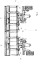
- Fig. 1 shows an agricultural machine 10 according to the invention with two arms 12, 14 in plan view, the central frame connecting the two arms 12, 14 not being shown for reasons of clarity.
- a working unit 16, 18 is carried by each of the arms 12, 14.
- the working unit 16, 18, which in the present example is designed as a belt swather, is each supported by a support device 20, 22 on the associated boom.
- an adjustment device 24, 26 is provided which can change the position of the working unit 16, 18 with respect to the boom 12, 14.
- Fig. 1 shows the working units 16, 18 in their working position in a state in which the working units 16, 18 lie next to one another.
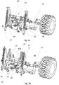
- Fig. 2a shows the boom 14 for the sake of clarity without the working unit 18 in the working position.
- the support device 22 comprises two spring-loaded links which form the lower links 32, 34 and an upper link cylinder 36 which forms the upper link.
- the links 32, 34 are connected to the boom 14 via ball-head bearings 38, 40. In addition to a vertical movement of the link, these also enable a lateral offset of the working unit 18 with respect to the boom 14.
- FIG. 2b shows the boom 14 with the support device 22 and the adjustment device 26 in the raised state or in the transport position.
- the adjusting device comprises an adjusting block 42 which is arranged pivotably with respect to the boom 14.
- Tie rods 44, 46 are connected to swivel arms 42a, 42b and cooperate at one end via an elongated hole with pins integrated in the swivel arms.
- the tie rods are connected to the working unit 18 via ball head bearings.
- the adjustment block 42 is pivoted via two excavation cylinders 48, 50 which are supported with respect to the boom 14. As a result, the working unit 18 can be lifted from the working position into the transport position or vice versa via the tie rods 44, 46.
- the adjustment device 26 comprises a lateral offset cylinder which is connected to the arm 14 of the working unit 18 via a ball-head bearing. This arrangement of the adjusting device 26 enables both excavation in the vertical direction and a lateral offset by hydraulic actuation of the excavation cylinder and the lateral offset cylinder.
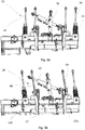
- Fig. 3a shows a boom 14 according to Fig. 2a in top view in the working position.
- the support device 22 described here which supports the working unit (not shown here), comprises the lower link 32 and the lower link 34 and is also guided by the upper link cylinder 36.
- the Lower links 32, 34 and the upper link cylinder are supported directly or indirectly with respect to the boom 14.
- the lower links 32, 34 are essentially orthogonal to the boom 14.
- Figure 3b shows the boom 14 according to Figure 2b in the transport position in plan view.
- the working unit 18, not shown is laterally offset towards the outside.
- the adjustment device 26 comprises two tie rods 44, 46, which are guided and held in a longitudinally displaceable manner by bolts on the pivot arms 42a, 42b of the adjustment block 42.
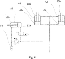
- the hydraulic interconnection is in Fig. 4 described in more detail.
- the piston spaces 48a, 50a of the excavation cylinders 48, 50 are connected to the piston space 52a of the side offset cylinder 52.
- the annular space 52b of the lateral offset cylinder 52 is connected to a pressure accumulator 54, so that the lateral offset cylinder 52 is pushed in when the oil pressure in the piston spaces 48a, 50a, 52a is correspondingly low.
- This situation exists in the floating position on a tractor control unit, so that in the working position the two working units 18, 16 are arranged next to one another, whereby in the event of a collision it is possible to evade against the pressure.
- the pressure accumulator 54 can only be effective when the piston space 52a is relieved via the associated valve.
- the lateral offset cylinder 52 is automatically extended when it is lifted, so that the distance between the working units 16, 18 is increased and a collision is avoided.
Landscapes
- Life Sciences & Earth Sciences (AREA)
- Engineering & Computer Science (AREA)
- Mechanical Engineering (AREA)
- Soil Sciences (AREA)
- Environmental Sciences (AREA)
- Zoology (AREA)
- Agricultural Machines (AREA)
- Soil Working Implements (AREA)
Claims (10)
- Machine agricole (10) comprenant un cadre central, qui porte au moins deux bras (12, 14), dans laquelle une unité de travail (16, 18) pour le traitement de la récolte est disposée sur chaque bras, dans laquelle un dispositif de support (20, 22) est prévu, par l'intermédiaire duquel l'unité de travail (16, 18) est maintenue sur le bras (12, 14), dans laquelle un dispositif de déplacement (24, 26) associé au bras est en outre prévu, qui peut amener l'unité de travail (16, 18) par rapport au bras (12, 14) dans une position de transport et dans une position de travail, dans laquelle, dans la position de transport, l'unité de travail (16, 18) est soulevée du sol et, dans la position de travail, repose sur le sol, dans laquelle le dispositif de déplacement (24, 26) comprend au moins un cylindre de déblai (48, 50), qui est directement ou indirectement soutenu par rapport au bras (12, 14) associé et qui est relié directement ou indirectement à l'unité de travail (16, 18), de sorte que, lorsque le cylindre de déblai (48, 50) est sollicité en pression, un décalage de l'unité de travail par rapport au bras s'effectue avec au moins une composante de mouvement verticale, dans laquelle le dispositif de déplacement (24, 26) comprend un cylindre de décalage latéral (52), qui est soutenu par rapport à l'unité de travail (16, 18) et au bras (12, 14) et, lors d'une sollicitation en pression, permet un mouvement de l'unité de travail (16, 18) avec une composante horizontale,
caractérisée en ce que l'au moins un cylindre de déblai (48, 50), avec sa première chambre de cylindre (48a, 50a) sollicitant le cylindre de déblai (48, 50) dans une direction de déblai, est regroupé avec la première chambre de cylindre (52a) du cylindre de décalage latéral (52), qui agit dans la direction de décalage. - Machine agricole selon la revendication 1, caractérisée en ce que la première chambre de cylindre est la chambre de piston (48a, 50a, 52a) du cylindre de déblai (48, 50, 52) et du cylindre de décalage latéral.
- Machine agricole selon l'une quelconque des revendications précédentes, caractérisée en ce que la deuxième chambre de cylindre, en particulier la chambre annulaire (52b), du cylindre de décalage latéral (52), est reliée à un accumulateur de pression (54).
- Machine agricole selon l'une quelconque des revendications précédentes, caractérisée en ce que le dispositif de déplacement (24, 26) comprend au moins une tige de traction (44, 46), par l'intermédiaire de laquelle l'unité de travail (16, 18) est reliée au cylindre de déblai (48, 50), de telle sorte que la tige de traction (44, 46), dans une position de transport, entraîne l'unité de travail (16, 18) dans la direction de déblai et, dans la position de travail, permet une mobilité libre dans la direction longitudinale de la tige de traction (44, 46) par rapport au cylindre de déblai (48, 50).
- Machine agricole selon la revendication 4, caractérisée en ce que le dispositif de déplacement (24, 26) comprend un bloc de déplacement (42), qui est disposé de manière pivotante par rapport au bras (12, 14), dans laquelle deux tiges de traction (44, 46) sont articulées par l'intermédiaire d'un bloc de déplacement (42).
- Machine agricole selon l'une des revendications précédentes 4 ou 5, caractérisée en ce que la tige de traction (44, 46) présente un élément de tige, qui est pourvu dans la direction longitudinale d'un trou oblong, qui coopère avec un axe entraîné avec le cylindre de déblai (48, 50).
- Machine agricole selon l'une quelconque des revendications précédentes, caractérisée en ce que le dispositif de support (20, 22) comprend au moins deux barres inférieures (32, 34), dans laquelle les barres sont reliées chacune par l'intermédiaire d'un palier à tête sphérique (38, 40) aussi bien au bras (12, 14) qu'à l'unité de travail (16, 18).
- Machine agricole selon l'une quelconque des revendications précédentes, caractérisée en ce que le dispositif de support comprend un cylindre de barre supérieure (36), qui est relié respectivement par l'intermédiaire d'un raccordement à tête sphérique à l'unité de travail (16, 18) et au bras (12, 14).
- Machine agricole selon l'une quelconque des revendications précédentes, caractérisée en ce que l'unité de travail (16, 18) est portée par l'intermédiaire de ce qu'on appelle des bols glisseurs ou patins.
- Machine agricole selon l'une quelconque des revendications précédentes, caractérisée en ce que l'unité de travail (16, 18) est un andaineur à tapis.
Applications Claiming Priority (1)
| Application Number | Priority Date | Filing Date | Title |
|---|---|---|---|
| DE102017112982.0A DE102017112982A1 (de) | 2017-06-13 | 2017-06-13 | Landwirtschaftliche Maschine |
Publications (2)
| Publication Number | Publication Date |
|---|---|
| EP3414981A1 EP3414981A1 (fr) | 2018-12-19 |
| EP3414981B1 true EP3414981B1 (fr) | 2020-12-30 |
Family
ID=62620760
Family Applications (1)
| Application Number | Title | Priority Date | Filing Date |
|---|---|---|---|
| EP18177300.3A Active EP3414981B1 (fr) | 2017-06-13 | 2018-06-12 | Machine agricole |
Country Status (2)
| Country | Link |
|---|---|
| EP (1) | EP3414981B1 (fr) |
| DE (1) | DE102017112982A1 (fr) |
Families Citing this family (2)
| Publication number | Priority date | Publication date | Assignee | Title |
|---|---|---|---|---|
| NL2021519B1 (nl) | 2018-08-30 | 2020-04-24 | Ploeger Oxbo Europe B V | Zelfrijdende landbouwmachine, bijvoorbeeld een zelfrijdende bandhark |
| DE102024126013A1 (de) * | 2024-09-10 | 2026-03-12 | Claas Saulgau Gmbh | Landwirtschaftliche Erntemaschine und Verfahren zum Betreiben derselben |
Citations (1)
| Publication number | Priority date | Publication date | Assignee | Title |
|---|---|---|---|---|
| US20150020492A1 (en) * | 2013-07-17 | 2015-01-22 | Kuhn S.A. | Machine for harvesting fodder |
Family Cites Families (6)
| Publication number | Priority date | Publication date | Assignee | Title |
|---|---|---|---|---|
| US4042044A (en) * | 1976-04-12 | 1977-08-16 | Deere & Company | Rear folding implement |
| DE4217375A1 (de) * | 1992-05-26 | 1993-12-02 | Claas Saulgau Gmbh | Landwirtschaftliche Arbeitsmaschine, besonders Kreiselheuwender |
| DE102004022534B4 (de) * | 2004-05-05 | 2012-01-26 | Claas Saulgau Gmbh | Erntemaschine zum Ernten von stängelartigem Erntegut wie Mais oder dergleichen |
| US7073604B1 (en) * | 2005-02-22 | 2006-07-11 | Morris Industries Ltd. | Hydraulic holding cylinder for wing lift mechanism |
| DE102005016350A1 (de) * | 2005-04-09 | 2006-10-12 | Maschinenfabrik Kemper Gmbh & Co. Kg | Erntevorsatz für landwirtschaftliche Erntemaschinen |
| FR2945403B1 (fr) * | 2009-05-14 | 2014-10-17 | Kuhn Sa | Machine de fenaison, notamment une andaineuse de vegetaux. |
-
2017
- 2017-06-13 DE DE102017112982.0A patent/DE102017112982A1/de not_active Withdrawn
-
2018
- 2018-06-12 EP EP18177300.3A patent/EP3414981B1/fr active Active
Patent Citations (1)
| Publication number | Priority date | Publication date | Assignee | Title |
|---|---|---|---|---|
| US20150020492A1 (en) * | 2013-07-17 | 2015-01-22 | Kuhn S.A. | Machine for harvesting fodder |
Also Published As
| Publication number | Publication date |
|---|---|
| DE102017112982A1 (de) | 2018-12-13 |
| EP3414981A1 (fr) | 2018-12-19 |
Similar Documents
| Publication | Publication Date | Title |
|---|---|---|
| EP3704928B1 (fr) | Machine de récolte et procédé de récolte au moyen d'une machine de récolte | |
| EP3612014B1 (fr) | Machine pour cultiver le sol | |
| EP3738419B1 (fr) | Équipement de préparation du sol | |
| DE102013107148B4 (de) | Absenkbares Rollenpaket eines sekundären Schneidwerks für einen Mähdrescher | |
| DE102016103475A1 (de) | Landwirtschaftliches Arbeitsgerät und Verfahren zum Ausführen einer Bodenanpassung in der Erntestellung desselben | |
| EP3414981B1 (fr) | Machine agricole | |
| EP2436251B1 (fr) | Faneuse destinée à retourner des récoltes se trouvant sur le sol | |
| EP3628142B1 (fr) | Dispositif de coupe pour un engin d'abattage-façonnage agricole ainsi que procédé de fonctionnement d'un dispositif de coupe | |
| EP4028599B1 (fr) | Élément de préhension | |
| EP1362506A1 (fr) | Ramasseur et dispositif de contrôle de la hauter | |
| EP3242543B1 (fr) | Engin agricole à châssis de roulement supplémentaire | |
| DE2536756A1 (de) | Ballenwagen mit auswahl der anordnung von ballen in ballengruppen eines ballenstapels | |
| EP4104654B1 (fr) | Appareil de traitement du sol à protection hydraulique contre les surcharges | |
| EP3763181B1 (fr) | Dispositif de récolte | |
| EP2661952B1 (fr) | Machine de fenaison | |
| EP4367997A1 (fr) | Andaineuse avec dispositif de ramassage | |
| EP3449716B1 (fr) | Ramasseuse-hacheuse ainsi que son procédé de fonctionnement | |
| DE69705346T2 (de) | Mähmaschine | |
| DE102006022480B4 (de) | Landwirtschaftliches Arbeitsgerät mit einem Tragrahmen | |
| DE102016103980B4 (de) | Landwirtschaftliches Vorsatzgerät und landwirtschaftliches Erntefahrzeug | |
| EP4706371A1 (fr) | Moissonneuse agricole et son procédé de fonctionnement | |
| DE102014110740B4 (de) | Landwirtschaftliches Arbeitsgerät | |
| DE102024103039A1 (de) | Maschine zum Mähen von stängelartigem Erntegut | |
| DE102015105215B4 (de) | Vorsatzgerät eines landwirtschaftlichen Erntefahrzeugs | |
| DE102015202178A1 (de) | Sicherheitsabstützung für einen Erntevorsatz |
Legal Events
| Date | Code | Title | Description |
|---|---|---|---|
| PUAI | Public reference made under article 153(3) epc to a published international application that has entered the european phase |
Free format text: ORIGINAL CODE: 0009012 |
|
| STAA | Information on the status of an ep patent application or granted ep patent |
Free format text: STATUS: THE APPLICATION HAS BEEN PUBLISHED |
|
| AK | Designated contracting states |
Kind code of ref document: A1 Designated state(s): AL AT BE BG CH CY CZ DE DK EE ES FI FR GB GR HR HU IE IS IT LI LT LU LV MC MK MT NL NO PL PT RO RS SE SI SK SM TR |
|
| AX | Request for extension of the european patent |
Extension state: BA ME |
|
| STAA | Information on the status of an ep patent application or granted ep patent |
Free format text: STATUS: REQUEST FOR EXAMINATION WAS MADE |
|
| 17P | Request for examination filed |
Effective date: 20190128 |
|
| RBV | Designated contracting states (corrected) |
Designated state(s): AL AT BE BG CH CY CZ DE DK EE ES FI FR GB GR HR HU IE IS IT LI LT LU LV MC MK MT NL NO PL PT RO RS SE SI SK SM TR |
|
| GRAP | Despatch of communication of intention to grant a patent |
Free format text: ORIGINAL CODE: EPIDOSNIGR1 |
|
| STAA | Information on the status of an ep patent application or granted ep patent |
Free format text: STATUS: GRANT OF PATENT IS INTENDED |
|
| INTG | Intention to grant announced |
Effective date: 20200528 |
|
| GRAJ | Information related to disapproval of communication of intention to grant by the applicant or resumption of examination proceedings by the epo deleted |
Free format text: ORIGINAL CODE: EPIDOSDIGR1 |
|
| STAA | Information on the status of an ep patent application or granted ep patent |
Free format text: STATUS: REQUEST FOR EXAMINATION WAS MADE |
|
| INTC | Intention to grant announced (deleted) | ||
| RAP1 | Party data changed (applicant data changed or rights of an application transferred) |
Owner name: REITER, THOMAS |
|
| RIN1 | Information on inventor provided before grant (corrected) |
Inventor name: REITER, THOMAS |
|
| GRAR | Information related to intention to grant a patent recorded |
Free format text: ORIGINAL CODE: EPIDOSNIGR71 |
|
| GRAS | Grant fee paid |
Free format text: ORIGINAL CODE: EPIDOSNIGR3 |
|
| STAA | Information on the status of an ep patent application or granted ep patent |
Free format text: STATUS: GRANT OF PATENT IS INTENDED |
|
| GRAA | (expected) grant |
Free format text: ORIGINAL CODE: 0009210 |
|
| STAA | Information on the status of an ep patent application or granted ep patent |
Free format text: STATUS: THE PATENT HAS BEEN GRANTED |
|
| INTG | Intention to grant announced |
Effective date: 20201119 |
|
| AK | Designated contracting states |
Kind code of ref document: B1 Designated state(s): AL AT BE BG CH CY CZ DE DK EE ES FI FR GB GR HR HU IE IS IT LI LT LU LV MC MK MT NL NO PL PT RO RS SE SI SK SM TR |
|
| REG | Reference to a national code |
Ref country code: GB Ref legal event code: FG4D Free format text: NOT ENGLISH |
|
| REG | Reference to a national code |
Ref country code: DE Ref legal event code: R096 Ref document number: 502018003440 Country of ref document: DE |
|
| REG | Reference to a national code |
Ref country code: AT Ref legal event code: REF Ref document number: 1348986 Country of ref document: AT Kind code of ref document: T Effective date: 20210115 |
|
| REG | Reference to a national code |
Ref country code: IE Ref legal event code: FG4D Free format text: LANGUAGE OF EP DOCUMENT: GERMAN |
|
| PG25 | Lapsed in a contracting state [announced via postgrant information from national office to epo] |
Ref country code: GR Free format text: LAPSE BECAUSE OF FAILURE TO SUBMIT A TRANSLATION OF THE DESCRIPTION OR TO PAY THE FEE WITHIN THE PRESCRIBED TIME-LIMIT Effective date: 20210331 Ref country code: NO Free format text: LAPSE BECAUSE OF FAILURE TO SUBMIT A TRANSLATION OF THE DESCRIPTION OR TO PAY THE FEE WITHIN THE PRESCRIBED TIME-LIMIT Effective date: 20210330 Ref country code: FI Free format text: LAPSE BECAUSE OF FAILURE TO SUBMIT A TRANSLATION OF THE DESCRIPTION OR TO PAY THE FEE WITHIN THE PRESCRIBED TIME-LIMIT Effective date: 20201230 Ref country code: RS Free format text: LAPSE BECAUSE OF FAILURE TO SUBMIT A TRANSLATION OF THE DESCRIPTION OR TO PAY THE FEE WITHIN THE PRESCRIBED TIME-LIMIT Effective date: 20201230 |
|
| PG25 | Lapsed in a contracting state [announced via postgrant information from national office to epo] |
Ref country code: BG Free format text: LAPSE BECAUSE OF FAILURE TO SUBMIT A TRANSLATION OF THE DESCRIPTION OR TO PAY THE FEE WITHIN THE PRESCRIBED TIME-LIMIT Effective date: 20210330 Ref country code: LV Free format text: LAPSE BECAUSE OF FAILURE TO SUBMIT A TRANSLATION OF THE DESCRIPTION OR TO PAY THE FEE WITHIN THE PRESCRIBED TIME-LIMIT Effective date: 20201230 Ref country code: SE Free format text: LAPSE BECAUSE OF FAILURE TO SUBMIT A TRANSLATION OF THE DESCRIPTION OR TO PAY THE FEE WITHIN THE PRESCRIBED TIME-LIMIT Effective date: 20201230 |
|
| REG | Reference to a national code |
Ref country code: NL Ref legal event code: MP Effective date: 20201230 |
|
| PG25 | Lapsed in a contracting state [announced via postgrant information from national office to epo] |
Ref country code: HR Free format text: LAPSE BECAUSE OF FAILURE TO SUBMIT A TRANSLATION OF THE DESCRIPTION OR TO PAY THE FEE WITHIN THE PRESCRIBED TIME-LIMIT Effective date: 20201230 |
|
| REG | Reference to a national code |
Ref country code: LT Ref legal event code: MG9D |
|
| PG25 | Lapsed in a contracting state [announced via postgrant information from national office to epo] |
Ref country code: LT Free format text: LAPSE BECAUSE OF FAILURE TO SUBMIT A TRANSLATION OF THE DESCRIPTION OR TO PAY THE FEE WITHIN THE PRESCRIBED TIME-LIMIT Effective date: 20201230 Ref country code: RO Free format text: LAPSE BECAUSE OF FAILURE TO SUBMIT A TRANSLATION OF THE DESCRIPTION OR TO PAY THE FEE WITHIN THE PRESCRIBED TIME-LIMIT Effective date: 20201230 Ref country code: PT Free format text: LAPSE BECAUSE OF FAILURE TO SUBMIT A TRANSLATION OF THE DESCRIPTION OR TO PAY THE FEE WITHIN THE PRESCRIBED TIME-LIMIT Effective date: 20210430 Ref country code: SK Free format text: LAPSE BECAUSE OF FAILURE TO SUBMIT A TRANSLATION OF THE DESCRIPTION OR TO PAY THE FEE WITHIN THE PRESCRIBED TIME-LIMIT Effective date: 20201230 Ref country code: EE Free format text: LAPSE BECAUSE OF FAILURE TO SUBMIT A TRANSLATION OF THE DESCRIPTION OR TO PAY THE FEE WITHIN THE PRESCRIBED TIME-LIMIT Effective date: 20201230 Ref country code: CZ Free format text: LAPSE BECAUSE OF FAILURE TO SUBMIT A TRANSLATION OF THE DESCRIPTION OR TO PAY THE FEE WITHIN THE PRESCRIBED TIME-LIMIT Effective date: 20201230 |
|
| PG25 | Lapsed in a contracting state [announced via postgrant information from national office to epo] |
Ref country code: PL Free format text: LAPSE BECAUSE OF FAILURE TO SUBMIT A TRANSLATION OF THE DESCRIPTION OR TO PAY THE FEE WITHIN THE PRESCRIBED TIME-LIMIT Effective date: 20201230 |
|
| PG25 | Lapsed in a contracting state [announced via postgrant information from national office to epo] |
Ref country code: IS Free format text: LAPSE BECAUSE OF FAILURE TO SUBMIT A TRANSLATION OF THE DESCRIPTION OR TO PAY THE FEE WITHIN THE PRESCRIBED TIME-LIMIT Effective date: 20210430 |
|
| REG | Reference to a national code |
Ref country code: DE Ref legal event code: R097 Ref document number: 502018003440 Country of ref document: DE |
|
| PG25 | Lapsed in a contracting state [announced via postgrant information from national office to epo] |
Ref country code: AL Free format text: LAPSE BECAUSE OF FAILURE TO SUBMIT A TRANSLATION OF THE DESCRIPTION OR TO PAY THE FEE WITHIN THE PRESCRIBED TIME-LIMIT Effective date: 20201230 Ref country code: IT Free format text: LAPSE BECAUSE OF FAILURE TO SUBMIT A TRANSLATION OF THE DESCRIPTION OR TO PAY THE FEE WITHIN THE PRESCRIBED TIME-LIMIT Effective date: 20201230 |
|
| PLBE | No opposition filed within time limit |
Free format text: ORIGINAL CODE: 0009261 |
|
| STAA | Information on the status of an ep patent application or granted ep patent |
Free format text: STATUS: NO OPPOSITION FILED WITHIN TIME LIMIT |
|
| PG25 | Lapsed in a contracting state [announced via postgrant information from national office to epo] |
Ref country code: DK Free format text: LAPSE BECAUSE OF FAILURE TO SUBMIT A TRANSLATION OF THE DESCRIPTION OR TO PAY THE FEE WITHIN THE PRESCRIBED TIME-LIMIT Effective date: 20201230 |
|
| 26N | No opposition filed |
Effective date: 20211001 |
|
| PG25 | Lapsed in a contracting state [announced via postgrant information from national office to epo] |
Ref country code: MC Free format text: LAPSE BECAUSE OF FAILURE TO SUBMIT A TRANSLATION OF THE DESCRIPTION OR TO PAY THE FEE WITHIN THE PRESCRIBED TIME-LIMIT Effective date: 20201230 Ref country code: ES Free format text: LAPSE BECAUSE OF FAILURE TO SUBMIT A TRANSLATION OF THE DESCRIPTION OR TO PAY THE FEE WITHIN THE PRESCRIBED TIME-LIMIT Effective date: 20201230 |
|
| REG | Reference to a national code |
Ref country code: CH Ref legal event code: PL |
|
| PG25 | Lapsed in a contracting state [announced via postgrant information from national office to epo] |
Ref country code: SI Free format text: LAPSE BECAUSE OF FAILURE TO SUBMIT A TRANSLATION OF THE DESCRIPTION OR TO PAY THE FEE WITHIN THE PRESCRIBED TIME-LIMIT Effective date: 20201230 |
|
| REG | Reference to a national code |
Ref country code: BE Ref legal event code: MM Effective date: 20210630 |
|
| PG25 | Lapsed in a contracting state [announced via postgrant information from national office to epo] |
Ref country code: LU Free format text: LAPSE BECAUSE OF NON-PAYMENT OF DUE FEES Effective date: 20210612 |
|
| PG25 | Lapsed in a contracting state [announced via postgrant information from national office to epo] |
Ref country code: LI Free format text: LAPSE BECAUSE OF NON-PAYMENT OF DUE FEES Effective date: 20210630 Ref country code: IE Free format text: LAPSE BECAUSE OF NON-PAYMENT OF DUE FEES Effective date: 20210612 Ref country code: CH Free format text: LAPSE BECAUSE OF NON-PAYMENT OF DUE FEES Effective date: 20210630 |
|
| PG25 | Lapsed in a contracting state [announced via postgrant information from national office to epo] |
Ref country code: IS Free format text: LAPSE BECAUSE OF FAILURE TO SUBMIT A TRANSLATION OF THE DESCRIPTION OR TO PAY THE FEE WITHIN THE PRESCRIBED TIME-LIMIT Effective date: 20210430 Ref country code: FR Free format text: LAPSE BECAUSE OF NON-PAYMENT OF DUE FEES Effective date: 20210630 |
|
| PG25 | Lapsed in a contracting state [announced via postgrant information from national office to epo] |
Ref country code: BE Free format text: LAPSE BECAUSE OF NON-PAYMENT OF DUE FEES Effective date: 20210630 |
|
| GBPC | Gb: european patent ceased through non-payment of renewal fee |
Effective date: 20220612 |
|
| PG25 | Lapsed in a contracting state [announced via postgrant information from national office to epo] |
Ref country code: GB Free format text: LAPSE BECAUSE OF NON-PAYMENT OF DUE FEES Effective date: 20220612 |
|
| PG25 | Lapsed in a contracting state [announced via postgrant information from national office to epo] |
Ref country code: NL Free format text: LAPSE BECAUSE OF NON-PAYMENT OF DUE FEES Effective date: 20201230 Ref country code: CY Free format text: LAPSE BECAUSE OF FAILURE TO SUBMIT A TRANSLATION OF THE DESCRIPTION OR TO PAY THE FEE WITHIN THE PRESCRIBED TIME-LIMIT Effective date: 20201230 |
|
| P01 | Opt-out of the competence of the unified patent court (upc) registered |
Effective date: 20230531 |
|
| PG25 | Lapsed in a contracting state [announced via postgrant information from national office to epo] |
Ref country code: SM Free format text: LAPSE BECAUSE OF FAILURE TO SUBMIT A TRANSLATION OF THE DESCRIPTION OR TO PAY THE FEE WITHIN THE PRESCRIBED TIME-LIMIT Effective date: 20201230 Ref country code: HU Free format text: LAPSE BECAUSE OF FAILURE TO SUBMIT A TRANSLATION OF THE DESCRIPTION OR TO PAY THE FEE WITHIN THE PRESCRIBED TIME-LIMIT; INVALID AB INITIO Effective date: 20180612 |
|
| PG25 | Lapsed in a contracting state [announced via postgrant information from national office to epo] |
Ref country code: MK Free format text: LAPSE BECAUSE OF FAILURE TO SUBMIT A TRANSLATION OF THE DESCRIPTION OR TO PAY THE FEE WITHIN THE PRESCRIBED TIME-LIMIT Effective date: 20201230 |
|
| REG | Reference to a national code |
Ref country code: AT Ref legal event code: MM01 Ref document number: 1348986 Country of ref document: AT Kind code of ref document: T Effective date: 20230612 |
|
| PG25 | Lapsed in a contracting state [announced via postgrant information from national office to epo] |
Ref country code: MT Free format text: LAPSE BECAUSE OF FAILURE TO SUBMIT A TRANSLATION OF THE DESCRIPTION OR TO PAY THE FEE WITHIN THE PRESCRIBED TIME-LIMIT Effective date: 20201230 |
|
| PG25 | Lapsed in a contracting state [announced via postgrant information from national office to epo] |
Ref country code: AT Free format text: LAPSE BECAUSE OF NON-PAYMENT OF DUE FEES Effective date: 20230612 |
|
| PG25 | Lapsed in a contracting state [announced via postgrant information from national office to epo] |
Ref country code: AT Free format text: LAPSE BECAUSE OF NON-PAYMENT OF DUE FEES Effective date: 20230612 |
|
| PGFP | Annual fee paid to national office [announced via postgrant information from national office to epo] |
Ref country code: DE Payment date: 20250610 Year of fee payment: 8 |
|
| PG25 | Lapsed in a contracting state [announced via postgrant information from national office to epo] |
Ref country code: TR Free format text: LAPSE BECAUSE OF FAILURE TO SUBMIT A TRANSLATION OF THE DESCRIPTION OR TO PAY THE FEE WITHIN THE PRESCRIBED TIME-LIMIT Effective date: 20201230 |
|
| PGFP | Annual fee paid to national office [announced via postgrant information from national office to epo] |
Ref country code: AT Payment date: 20260410 Year of fee payment: 5 |