EP3415032A1 - Fermoir pour accessoires et accessoire l'utilisant - Google Patents
Fermoir pour accessoires et accessoire l'utilisant Download PDFInfo
- Publication number
- EP3415032A1 EP3415032A1 EP17811174.6A EP17811174A EP3415032A1 EP 3415032 A1 EP3415032 A1 EP 3415032A1 EP 17811174 A EP17811174 A EP 17811174A EP 3415032 A1 EP3415032 A1 EP 3415032A1
- Authority
- EP
- European Patent Office
- Prior art keywords
- personal
- main body
- ornament
- closing member
- clasp
- Prior art date
- Legal status (The legal status is an assumption and is not a legal conclusion. Google has not performed a legal analysis and makes no representation as to the accuracy of the status listed.)
- Granted
Links
Images


Classifications
-
- A—HUMAN NECESSITIES
- A44—HABERDASHERY; JEWELLERY
- A44C—PERSONAL ADORNMENTS, e.g. JEWELLERY; COINS
- A44C11/00—Watch chains; Ornamental chains
- A44C11/005—Watch chains; Ornamental chains with friction boxes adjustments
-
- A—HUMAN NECESSITIES
- A44—HABERDASHERY; JEWELLERY
- A44C—PERSONAL ADORNMENTS, e.g. JEWELLERY; COINS
- A44C25/00—Miscellaneous fancy ware for personal wear, e.g. pendants, crosses, crucifixes, charms
- A44C25/001—Pendants
-
- A—HUMAN NECESSITIES
- A44—HABERDASHERY; JEWELLERY
- A44C—PERSONAL ADORNMENTS, e.g. JEWELLERY; COINS
- A44C5/00—Bracelets; Wrist-watch straps; Fastenings for bracelets or wrist-watch straps
- A44C5/18—Fasteners for straps, chains or the like
- A44C5/20—Fasteners for straps, chains or the like for open straps, chains or the like
- A44C5/2019—Hooks
- A44C5/2033—Hooks provided with pivoting closure means
- A44C5/2038—Swivels
-
- F—MECHANICAL ENGINEERING; LIGHTING; HEATING; WEAPONS; BLASTING
- F16—ENGINEERING ELEMENTS AND UNITS; GENERAL MEASURES FOR PRODUCING AND MAINTAINING EFFECTIVE FUNCTIONING OF MACHINES OR INSTALLATIONS; THERMAL INSULATION IN GENERAL
- F16B—DEVICES FOR FASTENING OR SECURING CONSTRUCTIONAL ELEMENTS OR MACHINE PARTS TOGETHER, e.g. NAILS, BOLTS, CIRCLIPS, CLAMPS, CLIPS OR WEDGES; JOINTS OR JOINTING
- F16B45/00—Hooks; Eyes
- F16B45/02—Hooks with pivoting or elastically bending closing member
- F16B45/024—Hooks with pivoting or elastically bending closing member and having means biasing the closing member about the pivot
- F16B45/026—Hooks with pivoting or elastically bending closing member and having means biasing the closing member about the pivot and including a coil type spring
-
- A—HUMAN NECESSITIES
- A44—HABERDASHERY; JEWELLERY
- A44C—PERSONAL ADORNMENTS, e.g. JEWELLERY; COINS
- A44C15/00—Other forms of jewellery
- A44C15/0045—Jewellery specially adapted to be worn on a specific part of the body not fully provided for in groups A44C1/00 - A44C9/00
- A44C15/005—Necklaces
-
- A—HUMAN NECESSITIES
- A44—HABERDASHERY; JEWELLERY
- A44D—INDEXING SCHEME RELATING TO BUTTONS, PINS, BUCKLES OR SLIDE FASTENERS, AND TO JEWELLERY, BRACELETS OR OTHER PERSONAL ADORNMENTS
- A44D2200/00—General types of fasteners
- A44D2200/10—Details of construction
Definitions
- the present invention relates to a personal-ornament clasp for annually locking a personal ornament such as a necklace to the body and, in particular, to a personal-ornament clasp capable of having a long chain-shaped personal ornament attached to the body while adjusting a retaining position.
- a personal ornament of PTL 1 has been disclosed.
- This ornament is a personal ornament for an ornamental chain of a necklace, and a cylinder body made of an elastic resin material is provided in an ornamental body. A small hole of the cylinder body is provided smaller than the diameter of the ornamental chain.
- a personal-ornament clasp of PTL 2 has an ornamental member main body with an ornament on a front surface, and this ornamental member main body is provided with first and second engaging members which engage with each other.
- the second engaging member is provided to the first engaging member so as to be rotatable about a fulcrum, and one engaging member is provided with a magnet and the other engaging member is provided with a magnet or a metal member.
- the engaging members are provided so as to be engageable with each other, and a long personal ornament main body is retained in a space portion between the engaging members in a state in which its retaining position is adjustable.
- the small hole of the cylinder body is provided so as to be smaller than the diameter of the ornamental chain.
- attachment and detachment take efforts, and attachment cannot be made with one touch.
- the cylinder body is intensely exhausted, thereby raising the possibility of weakening the locking force and damaging the ornamental chain.
- the cylinder body is elongated, and the size of the ornamental body is increased, thereby losing a balance between the ornamental chain and the ornamental body and degrading entire ornamental properties.
- the personal-ornament clasp of PTL 2 since the magnet and the metal member are provided to the ornamental member main body for engagement, the size of the ornamental member main body is increased to lose integration with the chain and impair ornamental properties.
- the personal ornament main body is provided by a pearl necklace. With this pearl having a size not passable through the space portion provided in an arc portion of the engaging members, the retaining position can be adjusted. In this manner, this clasp does not have a structure in which the ornamental member main body is directly nipped and attached by the engaging members. Thus, if the ornamental member main body is a thin chain, looseness may occur between the clasp and the ornamental member main body to deviate the retaining position to decrease attachability.
- the present invention was developed to solve the above-described circumstances, and has an object of providing a personal-ornament clasp and a personal ornament using the same which solve burdensome handling of the conventional clasp all at once, the personal-ornament clasp being able to easily attach and detach a long personal ornament to and from the body with one touch while adjusting a retaining position, in which even if the personal ornament is a thin chain, this personal ornament is strongly gripped without damage to hold the attachment position, thereby allowing prevention of a deviation, and an attachment/detachment portion is made compact to exert excellent ornamental properties.
- the invention according to claim 1 is directed to a personal-ornament clasp including: a holder on a fixed side having, on one end side, an arc-shaped holding portion where a long chain-shaped personal ornament main body is held via an opening; a closing member on a movable side rotatably attached to the holder via a pivotally attaching portion on another end side with the opening side and locking from inside the opening to cause a closed state; a soft member attached to this closing member at least on a side of gripping the personal ornament main body; and a spring attached in a repulsive state between the holder and the closing member and pressing the closing member in a direction of closing the opening, wherein a grip space where the personal ornament main body is gripped in the repulsive direction of the spring is provided between the soft member and the holding portion.
- the invention according to claim 2 is directed to the personal-ornament clasp in which the soft member is made of silicone or rubber with friction resistance, and is attached in a state of slightly protruding from the closing member to the grip space.
- the invention according to claim 3 is directed to the personal-ornament clasp in which the soft member is formed in a flat shape, and is fitted into the closing member as being surrounded inside.
- the invention according to claim 4 is directed to a personal-ornament clasp including : a holder on a fixed side having, on one end side, an arc-shaped holding portion where a long chain-shaped personal ornament main body is held via an opening; a closing member on a movable side rotatably attached to the holder via a pivotally attaching portion on another end side with the opening side and locking from inside the opening to cause a closed state; a soft member attached to an inner periphery of the holding portion; and a spring attached in a repulsive state between the holder and the closing member and pressing the closing member in a direction of closing the opening, wherein a grip space where the personal ornament main body is gripped is provided between the soft member and the closing member.
- the invention according to claim 5 is directed to the personal-ornament clasp in which the soft member is made of silicone or rubber with friction resistance.
- the invention according to claim 6 is directed to the personal-ornament clasp in which a personal ornament using a personal-ornament clasp in which the personal-ornament clasp is provided on one end side of a personal ornament main body.
- the invention according to claim 7 is directed to the personal ornament using the personal-ornament clasp in which an ornamental member larger than the grip space is attached to another end side of the personal ornament main body.
- the clasp includes: the holder on the fixed side having, on one end side, the arc-shaped holding portion via the opening; a closing member locking from inside the opening via the pivotally attaching portion to cause a closed state; the soft member attached to the closing member on the gripping side; and the spring which repulsively presses the holder and the closing member in the closing direction, and the personal ornament main body is provided in the grip space between the soft member and the holding portion so as to be able to be gripped by the resilient force of the spring.
- the soft member is made of silicone or rubber, thereby allowing the personal ornament main body to be attached and detached without damaging its surface. With this soft member attached in the state of slightly protruding to the grip space, gripping can be made while this soft member is reliably in contact with the personal ornament main body, the personal ornament main body is firmly held by friction resistance of the soft member to prevent a deviation and dropping after attachment, and fitness to the body can be maintained.
- the closing member is fabricated by press working or the like and simultaneously the soft member can be attached to the inside of this closing member.
- mass production can be made while the number of components and the number of processes are reduced.
- the soft member can be attached at an accurate position, its looseness or dropping after attachment are also prevented, and assembling is also performed with ease.
- the clasp includes: the holder on the fixed side having, on one end side, the arc-shaped holding portion via the opening; a closing member locking from inside the opening via the pivotally attaching portion to cause a closed state; the soft member attached to the inner periphery of the holding portion; and the spring which repulsively presses the holder and the closing member in the closing direction, and the personal ornament main body is provided in the grip space between the soft member and the holding portion so as to be able to be gripped.
- a pressing force is applied to the holder and the closing member as being nipped by fingers to cause the grip space to become in an open state, and the personal ornament main body is dropped into this grip space from the opening.
- the soft member is made of silicone or rubber, thereby allowing the personal ornament main body to be attached and detached without damaging its surface. After attachment of the personal ornament main body, the personal ornament main body is firmly held by friction resistance of the soft member to prevent a deviation and dropping after attachment, and fitness to the body can be maintained.
- the personal ornament main body can be easily attached to and detached from the body with one touch while the retaining position is adjusted. After attachment, the attachment state fitted to the body can be maintained.
- Various ornamental properties can be added to the personal ornament main body, and the personal ornament main body can be formed at any length, thereby extending the range of ornamentation.
- the ornamental member larger than the grip space is provided to the other end side of the clasp of the personal ornament main body. Even if a force in a dropping direction is applied to the other end side after attachment to the body, the ornamental member engages with the holder, thereby preventing its dropping to prevent falling from the body. This ornamental member further enhances ornament properties as a personal ornament.
- FIG. 1 Depicted in FIG. 1 is an embodiment of the personal ornament using the personal-ornament clasp of the present invention, depicted in FIG. 2 is an attached state of the personal ornament, and depicted in FIGs. 3A to 3B is a personal-ornament clasp for use in this personal ornament.
- the personal-ornament clasp in the present invention (hereinafter referred to as a clasp main body 1) is attached to a personal ornament main body 2 formed of a long chain-shaped necklace depicted in FIG. 1 and FIG. 2 .
- the personal ornament main body 2 is annularly connected to be provided attachably to and detachably from the body.
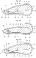
- the clasp main body 1 includes a holder 10, a soft member 11, a closing member 12, and a spring 13.
- the holder 10 is provided from an appropriate precious metal or metal material with ornamental properties so as to have an substantially hook-formed outer shape having a substantially U-shaped cross-section, and is provided as a side for fixing the personal ornament main body 2.
- an arc-shaped holding portion 20 is formed on one end side to which the personal ornament main body 2 is attached.
- an opening 21 is provided on an opening side of this holding portion 20, an opening 21 is provided.
- the opening 21 is formed so as to be able to attach and detach the personal ornament main body 2 to and from the holding portion 20 and be slightly wider than the thickness of this personal ornament main body 2. Via this opening 21, the personal ornament main body 2 can be held in the holding portion 20. Between the holder 10 and the closing member 12 to which the soft member 11 is attached, a grip space S, which will be described further below, is provided. In this grip space S, the personal ornament main body 2 is attached to the holding portion 20 via the soft member 11.
- a curved surface end 22 forming a mild curved surface is formed so as to be continued from the holding portion 20. Via this curved surface end 22, the personal ornament main body 2 can be guided to the holding portion 20 from the opening 21.
- a bowed portion 23 with a portion near its center recessed is formed on an opposite side of the curved surface end 22 of the holder 10.
- two communication holes 24, 24 are formed so as to cross an open and close direction of the closing member 12. Furthermore, at an end side from these communication holes 24, an attachment hole 25 for attaching a fixing side of the personal ornament main body 2 is formed.
- the closing member 12 has a curved-surface shape on its upper surface side and a bowed shape on its lower surface side in a front view of FIGs. 4A to 4C , and is formed to have a U-shaped cross section which can be accommodated inside the holder. Inside this U-shaped portion, the soft member 11 is attached. Through holes 26 are formed at positions of the closing member 12 corresponding to the communication holes 24. With these through holes 26 communicated with the communication holes 24, the closing member 12 is temporarily attached to the holder 10, and a pin 27 is inserted into these communication holes 24 and the through holes 26. Both ends of the pin 27 are fixed to the holder 10 by swaging, laser welding, or the like, thereby providing a pivotally attaching portion 28.
- the closing member 12 is rotatably attached to the holder 10 as a movable side via the pivotally attaching portion 28 on the other end side with the opening 21, and has its tip side lockable from the inside of the opening 21.
- the holder 10 and the closing member 12 are each made of, for example, a thin-plate-shaped precious metal such as 18K or silver having a thickness of 0.1 mm as a material, and are each integrally fabricated by processing means such as press working.
- the soft member 11 of FIG. 5 is formed of silicone with friction resistance to be long in a flat shape including a plate-shaped portion 30 and a broad portion 31 broader than this plate-shaped portion 30. Formed of silicone in this manner, the soft member 11 has a hardness allowing the personal ornament main body 2 to dig thereinto.
- the plate-shaped portion 30 is formed so as to have a thickness capable of fitting inside an inverted-C shape of the closing member 12.
- the broad portion 31 is formed on front and rear surfaces at the tip side (right side in FIG. 4A ) of the plate-shaped portion 30 so as to have a thick substantially equal to the width of the closing member 12.
- an appropriate smooth convex arc portion 32 is formed on the tip side of the broad portion 31 .
- a concave arc portion 33 capable of engaging with the tip side of the closing member 12 is formed.
- the soft member 11 is fitted into the closing member 12 in a state in which the plate-shaped portion 30 is surrounded inside, the concave arc portion 33 engages with a tip face of the closing member 12, and the convex arc portion 32 of the broad portion 31 is attached by means such as bonding to the closing member 12 in a state of slightly protruding (bulging) into the grip space S.
- the spring 13 of FIGs. 4A to 4C is made of a torsion coil spring, and has a coil portion 40, a free end 41 on one end side across this coil portion 40, and a folded portion 42 on the other end side.
- the spring 13 is attached between the holder 10 and the closing member 12 so as to be mutually repulsive to these members. This spring 13 causes the closing member 12 to be pressed in a direction of closing the opening 21.
- the closing member 12 is pressed in a leftward rotating direction of FIG. 4A by a resilient force of the spring 13. At normal times, the tip side of the closing member 12 locks in the opening 21 to cause a closed state.
- the closing member 12 and the holder 10 are both nipped and pressed against the resilient force of the spring 13, the closing member 12 rotates rightward while the soft member 11 is sliding over the inner periphery of the holder 10, and the opening 21 becomes in an open state as depicted in FIG. 4B .
- the grip space S is provided between the soft member 11 and the holding portion 20 as a space for gripping the personal ornament main body 2.
- the personal ornament main body 2 can be held as gripped in this grip space S toward the repulsive direction of the spring 13. Specifically, when the closing member 12 is pressed to a holder 10 side from a state of FIG. 4A and the closing member 12 moves into the inside of the holder 10 as in FIG. 4B , the grip space S is provided between the holding portion 20 and the closing member 12 via the soft member 11. To the holding portion 20 in this grip space S, the personal ornament main body 2 is attached as indicated by a two-dot-chain line of FIG. 4C . In this state, by releasing the pressing of the closing member 12 and the holder 10, the personal ornament main body 2 is gripped between the holding portion 20 and the soft member 11 by the resilient force of the spring 13.
- the personal ornament main body 2 depicted in FIG. 1 is formed of a precious metal such as gold, silver, or platinum, another metal material, or the like in a long chain shape, and a general one can be used.
- the personal ornament main body 2 has chain elements 2a, and the chain element 2a at one end is attached in the attachment hole 25 of the clasp main body 1.
- an appropriate ornamental member 50 is attached to the chain element 2a at the other end. This ornamental member 50 is formed larger than the grip space S of the clasp main body 1.
- the soft member 11 may be attached to the holder 10 side if the soft member 11 protrudes to the grip space S side to be able to attach and detach the personal ornament main body 2 between the holder 10 and the closing member 12. Even if being provided on either side, the soft member 11 may be provided in a compact shape that can be arranged only on the grip space S side. In this case, although not depicted, for example, if a lock hole is provided to the closing member and a stopper piece that can be locked into this lock hole is provided to the soft member, these locking can position and fix the soft member to the closing member. According to this, the material of the soft member is reduced, and attachment is facilitated. Furthermore, since the folded portion for fixation to the soft member is not required to be provided to the spring, flexibility when the spring is processed is also improved.
- the soft member 11 may be made of a material other than silicone if the material can produce appropriate friction resistance, and may be formed of rubber, for example. While the soft member 11 is formed to be long and is arranged over the closing member 12 approximately in its entirety in the present embodiment, the soft member 11 may be in a shape that can be arranged only a portion near the tip end side of the closing member 12 if the personal ornament main body 2 can be gripped.
- the personal ornament main body 2 is not limited to a chain shape and, for example, may have appropriate ornamental properties such as a string shape.
- the ornamental member 50 may be attachable to and detachable from the personal ornament main body 2, integrally provided, or omitted.
- the clasp main body 1 can be provided in an appropriated shape or be provided with any ornament if the clasp main body 1 has a fastening structure of gripping the personal ornament main body 2 in the grip space S via the soft member 11 between the holding portion 20 and the closing member 12.
- the size of the grip space S may be appropriately set in accordance with the thickness of the personal ornament main body 2.
- the clasp main body 1 and the ornamental member 50 are positioned in front of the body (chest or belly side), and the personal ornament main body 2 is worn on the neck while the lengths at both end of the clasp main body 1.
- the closing member 12 and the holder 10 of FIG. 3A and FIG. 4A are nipped by a finger, and these are pressed against the resilient force of the torsion coil spring 13, thereby causing the closing member 12 to rotate rightward about the pivotally attaching portion 28 in FIGs. 4A to 4C , and the opening 21 is opened to such an extent that the upper surface side of the closing member 12 is substantially equal to a portion near the upper surface of the holder 10.
- the closing member 12 and the holder 10 can be easily operated to be opened with a light force of a finger of one hand.
- the torsion coil spring 13 as depicted in FIG. 4B , its free end 41 is deformed along a bowed portion on the inner periphery of the holder 10 to be able to exert a resilient force.
- the personal ornament main body 2 After the personal ornament main body 2 is attached, with an elastic force and friction resistance the soft member 11 has in addition to the resilient force of the spring 13, the personal ornament main body 2 is firmly held between the soft member 11 and the holding portion 20, and sliding is also inhibited. With this, even if the thickness of each chain element 2a forming the personal ornament main body 2 is varied, a strong grip force can be exerted in accordance with its thickness to retain attachability. Thus, excellent versatility can be achieved. Even if an outer force is applied after attachment, a deviation between the clasp main body 1 and the personal ornament main body 2 and dropping thereof are prevented to maintain an attached state. After the personal ornament main body 2 is gripped between the soft member 11 and the holding portion 20, its gripped portion does not bulge outward, and compactability of the clasp main body 1 is maintained.
- the clasp main body 1 has a smooth curved line shape as a whole, integration with the personal ornament main body 2 is improved, and the clasp main body 1 can ergonomically fit along the body together with this personal ornament main body 2. While the closing member 12 having the soft member 11 attached thereto is accommodated inside the holder 10, compactization can be achieved as the entirety is made narrower. Also, since there is no protrusion pointed outward, excellent beauty of function is achieved, for example, there is no obstruction to attachment, there is no snag in clothing or hair, and erroneous operation can also be prevented.
- the locking position and the left and right lengths of the personal ornament main body 2 can be easily adjusted at the time of wearing or after wearing.
- the closing member 12 and the holder 10 are nipped by fingers to release the grip force to the personal ornament main body 2 by the pressing force and, in this state, the personal ornament main body 2 is slid to the holding portion 20 to allow adjustment of the attachment position. In this manner, adjustment can be easily made without removal of the personal ornament main body 2.
- the closing member 12 With the closing member 12 always pressed by the torsion coil spring 13 in the closing direction, the closing member 12 is inhibited from loosing naturally to open the opening 21, thereby preventing dropping of the personal ornament main body 2. In this manner, since the personal ornament main body 2 is gripped by using the resilient force of the torsion coil spring 13, the gripping force is maintained even when the closing member 12 is repeatedly opened and closed. At normal times, the tip side of the closing member 12 locks from the inside of the opening 21, thereby preventing the closing member 12 from protruding outward even though the resilient force of the torsion coil spring 13 is applied to this closing member 12.
- the soft member 11 is formed in a flat shape, and is structured to be fitted into the closing member 12 as being surrounded inside.
- the soft member 11 can be fixedly attached at a predetermined position inside this closing member 12 simultaneously with fabrication of the closing member 12 by press working or the like.
- the plate-shaped portion 30 is formed as being in a long shape, and this plate-shaped portion 30 fits inside the closing member 12. This increases a contact area between the soft member 11 and the closing member 12 to prevent a deviation of the soft member 11 after fixed attachment, and durability with respect to repeated use is enhanced. Furthermore, productivity, assembling capability, and workability are also favorable.
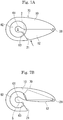
- FIGs. 6A to 6B a second embodiment of the personal-ornament clasp in the present invention is depicted. Note that in the following embodiments, portions identical to those of the above-described embodiment are provided with the same reference characters and their description is omitted.
- a groove-shaped region is formed inside a holding portion 61, and a soft member 62 made of silicone is accommodated in this groove-shaped region.
- a plurality of claw portions not depicted are provided on both edges of the groove portion. With these claw portions folded after accommodation of the soft member 62, the soft member 62 is attached inside the holding portion 61 in a state of being fixed therein.
- a smooth round surface 63 is provided on an inner peripheral side of the soft member 62 after attachment to the holding portion 61.
- This round surface 63 provides a gap for attaching the personal ornament main body 2.
- the soft member 62 is attached to the holder 10 on a fixed side, and the grip space S where the personal ornament main body 2 is gripped is provided between the soft member 62 and the closing member 12.
- FIG. 6A Depicted in FIG. 6A is a closed state of the clasp main body 60, and depicted in FIG. 6B is an open state of the clasp main body 60. With the closed state of FIG. 6A , as with the above-described embodiment, the personal ornament main body 2 can be firmly gripped.
- FIGs. 7A to 7B a third embodiment of the personal-ornament clasp in the present invention is depicted.
- This clasp main body 70 is provided with the clasp main body 60 of FIGs. 6A to 6B which is short in a length direction. Also in this case, as depicted in a closed state of FIG. 7A and an opening state of FIG. 7B and as with the clasp main body 60 of FIGs. 6A to 6B , the closing member 12 can be pressed as being nipped to open and close an open/close portion. In this case, compactization can be achieved compared with the clasp main body 60 of FIGs. 6A to 6B .
- the present invention solves the conventional inconvenience of the clasp, a user-satisfying clasp can be provided and, in particular, the present invention is not meant to be limited to the description of the embodiments and can be variously modified in a range not deviating from the spirit of the invention described in the scope of claims for patent of the present invention.
Landscapes
- Engineering & Computer Science (AREA)
- General Engineering & Computer Science (AREA)
- Mechanical Engineering (AREA)
- Adornments (AREA)
Applications Claiming Priority (2)
| Application Number | Priority Date | Filing Date | Title |
|---|---|---|---|
| JP2017077500 | 2017-04-10 | ||
| PCT/JP2017/025703 WO2018189918A1 (fr) | 2017-04-10 | 2017-07-14 | Fermoir pour accessoires et accessoire l'utilisant |
Publications (3)
| Publication Number | Publication Date |
|---|---|
| EP3415032A1 true EP3415032A1 (fr) | 2018-12-19 |
| EP3415032A4 EP3415032A4 (fr) | 2019-04-24 |
| EP3415032B1 EP3415032B1 (fr) | 2020-02-12 |
Family
ID=63792646
Family Applications (1)
| Application Number | Title | Priority Date | Filing Date |
|---|---|---|---|
| EP17811174.6A Active EP3415032B1 (fr) | 2017-04-10 | 2017-07-14 | Fermoir pour accessoires et accessoire l'utilisant |
Country Status (5)
| Country | Link |
|---|---|
| US (1) | US10709217B2 (fr) |
| EP (1) | EP3415032B1 (fr) |
| JP (1) | JP6596513B2 (fr) |
| CN (1) | CN109068817A (fr) |
| WO (1) | WO2018189918A1 (fr) |
Families Citing this family (7)
| Publication number | Priority date | Publication date | Assignee | Title |
|---|---|---|---|---|
| US11317684B1 (en) * | 2018-10-25 | 2022-05-03 | Misa Design, LLC | Necklace having integrated pendant anchor |
| CN109757836B (zh) * | 2019-01-03 | 2020-12-25 | 郑海宁 | 一种链扣及其制造设备和制造方法 |
| US10858222B1 (en) | 2019-06-18 | 2020-12-08 | Christopher Laarman | Couplers with partially open gates |
| US20210259165A1 (en) * | 2020-02-24 | 2021-08-26 | Lillian C. Rauch | Clothing and fashion accessories for plants |
| CN115244406B (zh) * | 2020-03-16 | 2025-07-25 | 亿酷科株式会社 | 紧固件 |
| US20220265512A1 (en) * | 2021-02-22 | 2022-08-25 | Jessica Lopera | Chakra Aligning Wellness Wear |
| USD989657S1 (en) * | 2022-02-26 | 2023-06-20 | Cartier International Ag | Charm |
Family Cites Families (15)
| Publication number | Priority date | Publication date | Assignee | Title |
|---|---|---|---|---|
| US731162A (en) * | 1902-12-31 | 1903-06-16 | Charles W Carter | Snap-hook. |
| US1746054A (en) * | 1927-02-09 | 1930-02-04 | Ridabock Alice Budd | Holding device for necklaces |
| US4628708A (en) * | 1983-02-24 | 1986-12-16 | Ivey Alma T | Jewelry chain organizer |
| US4754534A (en) * | 1987-01-15 | 1988-07-05 | Helwick Carol S | Jewelry clip |
| JPH03132896A (ja) | 1989-10-19 | 1991-06-06 | Fuji Electric Co Ltd | 飲料自動販売機の飲料水殺菌装置 |
| US5117539A (en) * | 1991-09-03 | 1992-06-02 | Shrader James P | Clasp mechanism |
| US5687585A (en) * | 1996-02-09 | 1997-11-18 | Ferrell; Kathryn L. | Necklace chain separation device and a multiple strand necklace unit |
| JP3829158B2 (ja) * | 1996-04-04 | 2006-10-04 | 株式会社ヤマ | 装身具用ジョイント |
| JP3041020U (ja) * | 1997-02-28 | 1997-09-05 | 株式会社ムラオ | 長さ調節式ネックレス |
| JPH10295421A (ja) | 1997-05-01 | 1998-11-10 | J C S:Kk | 装飾チエーン用の装飾具と止め具 |
| US6308385B1 (en) * | 1999-11-29 | 2001-10-30 | Peter Franklin Ball | Jewelry clasp |
| JP2001224412A (ja) * | 2000-02-18 | 2001-08-21 | Kosaikogei Co Ltd | 装身具用止め金具 |
| JP2006325657A (ja) * | 2005-05-23 | 2006-12-07 | Yasuo Kawahara | 装身具用留め具 |
| US9777763B2 (en) * | 2010-09-14 | 2017-10-03 | Lucy A. Mitchell | Hook with magnetic closure |
| JPWO2016121088A1 (ja) * | 2015-01-30 | 2017-11-09 | 雅弘 星野 | 留め具 |
-
2017
- 2017-07-14 CN CN201780002154.6A patent/CN109068817A/zh active Pending
- 2017-07-14 JP JP2017558754A patent/JP6596513B2/ja active Active
- 2017-07-14 EP EP17811174.6A patent/EP3415032B1/fr active Active
- 2017-07-14 WO PCT/JP2017/025703 patent/WO2018189918A1/fr not_active Ceased
- 2017-07-14 US US15/736,584 patent/US10709217B2/en not_active Expired - Fee Related
Also Published As
| Publication number | Publication date |
|---|---|
| EP3415032B1 (fr) | 2020-02-12 |
| EP3415032A4 (fr) | 2019-04-24 |
| JPWO2018189918A1 (ja) | 2019-06-27 |
| US20180352917A1 (en) | 2018-12-13 |
| JP6596513B2 (ja) | 2019-10-23 |
| US10709217B2 (en) | 2020-07-14 |
| CN109068817A (zh) | 2018-12-21 |
| WO2018189918A1 (fr) | 2018-10-18 |
Similar Documents
| Publication | Publication Date | Title |
|---|---|---|
| EP3415032B1 (fr) | Fermoir pour accessoires et accessoire l'utilisant | |
| CN101371724A (zh) | 带用带扣以及具备带用带扣的身体穿戴装置 | |
| US3698044A (en) | Clutch mechanism for jewelry pin | |
| US12082657B2 (en) | Belt buckle system | |
| US20070251268A1 (en) | Clip for an ornamental item | |
| CN107581726B (zh) | 表带 | |
| EP2995214B1 (fr) | Instrument d'ouverture destiné à un fermoir d'accessoire | |
| US20230346085A1 (en) | Jewelry Clasp Opening Tool | |
| CN105901849A (zh) | 具有扩展表带的手表 | |
| CN111513436A (zh) | 金属表带 | |
| US20110173782A1 (en) | Split arm clip | |
| GB2333260A (en) | Jewellery clasp clamping device | |
| US7712643B2 (en) | Jewelry fastening aid | |
| US11540597B1 (en) | Belt buckle system | |
| JP2025107619A (ja) | 中留及びバンド | |
| CN110573040B (zh) | 人身装饰品等的卡扣 | |
| KR20160138539A (ko) | 보석용 공구 | |
| EP0253771B1 (fr) | Fermoir pour parure | |
| HK1261129A1 (zh) | 人身装饰品用卡扣和使用其的人身装饰品 | |
| US20250229384A1 (en) | Jewelry opening device and method of opening a jewelry fastener | |
| JP3726157B2 (ja) | 合成樹脂製クリップ | |
| JP6876314B1 (ja) | 装身具の止め具 | |
| KR20200039609A (ko) | 장신구용 잠금쇠 | |
| KR20180132244A (ko) | 장신구의 체결장치 | |
| JPH0354570Y2 (fr) |
Legal Events
| Date | Code | Title | Description |
|---|---|---|---|
| STAA | Information on the status of an ep patent application or granted ep patent |
Free format text: STATUS: UNKNOWN |
|
| STAA | Information on the status of an ep patent application or granted ep patent |
Free format text: STATUS: THE INTERNATIONAL PUBLICATION HAS BEEN MADE |
|
| PUAI | Public reference made under article 153(3) epc to a published international application that has entered the european phase |
Free format text: ORIGINAL CODE: 0009012 |
|
| STAA | Information on the status of an ep patent application or granted ep patent |
Free format text: STATUS: REQUEST FOR EXAMINATION WAS MADE |
|
| 17P | Request for examination filed |
Effective date: 20171218 |
|
| AK | Designated contracting states |
Kind code of ref document: A1 Designated state(s): AL AT BE BG CH CY CZ DE DK EE ES FI FR GB GR HR HU IE IS IT LI LT LU LV MC MK MT NL NO PL PT RO RS SE SI SK SM TR |
|
| AX | Request for extension of the european patent |
Extension state: BA ME |
|
| R17P | Request for examination filed (corrected) |
Effective date: 20171218 |
|
| A4 | Supplementary search report drawn up and despatched |
Effective date: 20190325 |
|
| RIC1 | Information provided on ipc code assigned before grant |
Ipc: A44C 15/00 20060101ALN20190319BHEP Ipc: A44C 5/20 20060101AFI20190319BHEP |
|
| REG | Reference to a national code |
Ref country code: DE Ref legal event code: R079 Ref document number: 602017011784 Country of ref document: DE Free format text: PREVIOUS MAIN CLASS: A44C0025000000 Ipc: A44C0005200000 |
|
| GRAP | Despatch of communication of intention to grant a patent |
Free format text: ORIGINAL CODE: EPIDOSNIGR1 |
|
| RIC1 | Information provided on ipc code assigned before grant |
Ipc: A44C 5/20 20060101AFI20190725BHEP Ipc: A44C 15/00 20060101ALN20190725BHEP |
|
| STAA | Information on the status of an ep patent application or granted ep patent |
Free format text: STATUS: GRANT OF PATENT IS INTENDED |
|
| DAV | Request for validation of the european patent (deleted) | ||
| DAX | Request for extension of the european patent (deleted) | ||
| INTG | Intention to grant announced |
Effective date: 20190829 |
|
| GRAS | Grant fee paid |
Free format text: ORIGINAL CODE: EPIDOSNIGR3 |
|
| GRAA | (expected) grant |
Free format text: ORIGINAL CODE: 0009210 |
|
| STAA | Information on the status of an ep patent application or granted ep patent |
Free format text: STATUS: THE PATENT HAS BEEN GRANTED |
|
| AK | Designated contracting states |
Kind code of ref document: B1 Designated state(s): AL AT BE BG CH CY CZ DE DK EE ES FI FR GB GR HR HU IE IS IT LI LT LU LV MC MK MT NL NO PL PT RO RS SE SI SK SM TR |
|
| REG | Reference to a national code |
Ref country code: GB Ref legal event code: FG4D |
|
| REG | Reference to a national code |
Ref country code: CH Ref legal event code: EP |
|
| REG | Reference to a national code |
Ref country code: AT Ref legal event code: REF Ref document number: 1230938 Country of ref document: AT Kind code of ref document: T Effective date: 20200215 |
|
| REG | Reference to a national code |
Ref country code: IE Ref legal event code: FG4D |
|
| REG | Reference to a national code |
Ref country code: DE Ref legal event code: R096 Ref document number: 602017011784 Country of ref document: DE |
|
| PG25 | Lapsed in a contracting state [announced via postgrant information from national office to epo] |
Ref country code: NO Free format text: LAPSE BECAUSE OF FAILURE TO SUBMIT A TRANSLATION OF THE DESCRIPTION OR TO PAY THE FEE WITHIN THE PRESCRIBED TIME-LIMIT Effective date: 20200512 Ref country code: FI Free format text: LAPSE BECAUSE OF FAILURE TO SUBMIT A TRANSLATION OF THE DESCRIPTION OR TO PAY THE FEE WITHIN THE PRESCRIBED TIME-LIMIT Effective date: 20200212 Ref country code: RS Free format text: LAPSE BECAUSE OF FAILURE TO SUBMIT A TRANSLATION OF THE DESCRIPTION OR TO PAY THE FEE WITHIN THE PRESCRIBED TIME-LIMIT Effective date: 20200212 |
|
| REG | Reference to a national code |
Ref country code: LT Ref legal event code: MG4D |
|
| REG | Reference to a national code |
Ref country code: NL Ref legal event code: MP Effective date: 20200212 |
|
| PG25 | Lapsed in a contracting state [announced via postgrant information from national office to epo] |
Ref country code: HR Free format text: LAPSE BECAUSE OF FAILURE TO SUBMIT A TRANSLATION OF THE DESCRIPTION OR TO PAY THE FEE WITHIN THE PRESCRIBED TIME-LIMIT Effective date: 20200212 Ref country code: GR Free format text: LAPSE BECAUSE OF FAILURE TO SUBMIT A TRANSLATION OF THE DESCRIPTION OR TO PAY THE FEE WITHIN THE PRESCRIBED TIME-LIMIT Effective date: 20200513 Ref country code: BG Free format text: LAPSE BECAUSE OF FAILURE TO SUBMIT A TRANSLATION OF THE DESCRIPTION OR TO PAY THE FEE WITHIN THE PRESCRIBED TIME-LIMIT Effective date: 20200512 Ref country code: LV Free format text: LAPSE BECAUSE OF FAILURE TO SUBMIT A TRANSLATION OF THE DESCRIPTION OR TO PAY THE FEE WITHIN THE PRESCRIBED TIME-LIMIT Effective date: 20200212 Ref country code: SE Free format text: LAPSE BECAUSE OF FAILURE TO SUBMIT A TRANSLATION OF THE DESCRIPTION OR TO PAY THE FEE WITHIN THE PRESCRIBED TIME-LIMIT Effective date: 20200212 Ref country code: IS Free format text: LAPSE BECAUSE OF FAILURE TO SUBMIT A TRANSLATION OF THE DESCRIPTION OR TO PAY THE FEE WITHIN THE PRESCRIBED TIME-LIMIT Effective date: 20200612 |
|
| PG25 | Lapsed in a contracting state [announced via postgrant information from national office to epo] |
Ref country code: NL Free format text: LAPSE BECAUSE OF FAILURE TO SUBMIT A TRANSLATION OF THE DESCRIPTION OR TO PAY THE FEE WITHIN THE PRESCRIBED TIME-LIMIT Effective date: 20200212 |
|
| PG25 | Lapsed in a contracting state [announced via postgrant information from national office to epo] |
Ref country code: CZ Free format text: LAPSE BECAUSE OF FAILURE TO SUBMIT A TRANSLATION OF THE DESCRIPTION OR TO PAY THE FEE WITHIN THE PRESCRIBED TIME-LIMIT Effective date: 20200212 Ref country code: RO Free format text: LAPSE BECAUSE OF FAILURE TO SUBMIT A TRANSLATION OF THE DESCRIPTION OR TO PAY THE FEE WITHIN THE PRESCRIBED TIME-LIMIT Effective date: 20200212 Ref country code: SK Free format text: LAPSE BECAUSE OF FAILURE TO SUBMIT A TRANSLATION OF THE DESCRIPTION OR TO PAY THE FEE WITHIN THE PRESCRIBED TIME-LIMIT Effective date: 20200212 Ref country code: DK Free format text: LAPSE BECAUSE OF FAILURE TO SUBMIT A TRANSLATION OF THE DESCRIPTION OR TO PAY THE FEE WITHIN THE PRESCRIBED TIME-LIMIT Effective date: 20200212 Ref country code: PT Free format text: LAPSE BECAUSE OF FAILURE TO SUBMIT A TRANSLATION OF THE DESCRIPTION OR TO PAY THE FEE WITHIN THE PRESCRIBED TIME-LIMIT Effective date: 20200705 Ref country code: ES Free format text: LAPSE BECAUSE OF FAILURE TO SUBMIT A TRANSLATION OF THE DESCRIPTION OR TO PAY THE FEE WITHIN THE PRESCRIBED TIME-LIMIT Effective date: 20200212 Ref country code: LT Free format text: LAPSE BECAUSE OF FAILURE TO SUBMIT A TRANSLATION OF THE DESCRIPTION OR TO PAY THE FEE WITHIN THE PRESCRIBED TIME-LIMIT Effective date: 20200212 Ref country code: SM Free format text: LAPSE BECAUSE OF FAILURE TO SUBMIT A TRANSLATION OF THE DESCRIPTION OR TO PAY THE FEE WITHIN THE PRESCRIBED TIME-LIMIT Effective date: 20200212 Ref country code: EE Free format text: LAPSE BECAUSE OF FAILURE TO SUBMIT A TRANSLATION OF THE DESCRIPTION OR TO PAY THE FEE WITHIN THE PRESCRIBED TIME-LIMIT Effective date: 20200212 |
|
| REG | Reference to a national code |
Ref country code: DE Ref legal event code: R097 Ref document number: 602017011784 Country of ref document: DE |
|
| REG | Reference to a national code |
Ref country code: AT Ref legal event code: MK05 Ref document number: 1230938 Country of ref document: AT Kind code of ref document: T Effective date: 20200212 |
|
| PLBE | No opposition filed within time limit |
Free format text: ORIGINAL CODE: 0009261 |
|
| STAA | Information on the status of an ep patent application or granted ep patent |
Free format text: STATUS: NO OPPOSITION FILED WITHIN TIME LIMIT |
|
| 26N | No opposition filed |
Effective date: 20201113 |
|
| PG25 | Lapsed in a contracting state [announced via postgrant information from national office to epo] |
Ref country code: AT Free format text: LAPSE BECAUSE OF FAILURE TO SUBMIT A TRANSLATION OF THE DESCRIPTION OR TO PAY THE FEE WITHIN THE PRESCRIBED TIME-LIMIT Effective date: 20200212 Ref country code: IT Free format text: LAPSE BECAUSE OF FAILURE TO SUBMIT A TRANSLATION OF THE DESCRIPTION OR TO PAY THE FEE WITHIN THE PRESCRIBED TIME-LIMIT Effective date: 20200212 |
|
| REG | Reference to a national code |
Ref country code: DE Ref legal event code: R119 Ref document number: 602017011784 Country of ref document: DE |
|
| PG25 | Lapsed in a contracting state [announced via postgrant information from national office to epo] |
Ref country code: PL Free format text: LAPSE BECAUSE OF FAILURE TO SUBMIT A TRANSLATION OF THE DESCRIPTION OR TO PAY THE FEE WITHIN THE PRESCRIBED TIME-LIMIT Effective date: 20200212 Ref country code: SI Free format text: LAPSE BECAUSE OF FAILURE TO SUBMIT A TRANSLATION OF THE DESCRIPTION OR TO PAY THE FEE WITHIN THE PRESCRIBED TIME-LIMIT Effective date: 20200212 Ref country code: MC Free format text: LAPSE BECAUSE OF FAILURE TO SUBMIT A TRANSLATION OF THE DESCRIPTION OR TO PAY THE FEE WITHIN THE PRESCRIBED TIME-LIMIT Effective date: 20200212 |
|
| REG | Reference to a national code |
Ref country code: CH Ref legal event code: PL |
|
| REG | Reference to a national code |
Ref country code: BE Ref legal event code: MM Effective date: 20200731 |
|
| PG25 | Lapsed in a contracting state [announced via postgrant information from national office to epo] |
Ref country code: CH Free format text: LAPSE BECAUSE OF NON-PAYMENT OF DUE FEES Effective date: 20200731 Ref country code: FR Free format text: LAPSE BECAUSE OF NON-PAYMENT OF DUE FEES Effective date: 20200731 Ref country code: LU Free format text: LAPSE BECAUSE OF NON-PAYMENT OF DUE FEES Effective date: 20200714 Ref country code: LI Free format text: LAPSE BECAUSE OF NON-PAYMENT OF DUE FEES Effective date: 20200731 |
|
| PG25 | Lapsed in a contracting state [announced via postgrant information from national office to epo] |
Ref country code: BE Free format text: LAPSE BECAUSE OF NON-PAYMENT OF DUE FEES Effective date: 20200731 Ref country code: DE Free format text: LAPSE BECAUSE OF NON-PAYMENT OF DUE FEES Effective date: 20210202 |
|
| PG25 | Lapsed in a contracting state [announced via postgrant information from national office to epo] |
Ref country code: IE Free format text: LAPSE BECAUSE OF NON-PAYMENT OF DUE FEES Effective date: 20200714 |
|
| GBPC | Gb: european patent ceased through non-payment of renewal fee |
Effective date: 20210714 |
|
| PG25 | Lapsed in a contracting state [announced via postgrant information from national office to epo] |
Ref country code: GB Free format text: LAPSE BECAUSE OF NON-PAYMENT OF DUE FEES Effective date: 20210714 |
|
| PG25 | Lapsed in a contracting state [announced via postgrant information from national office to epo] |
Ref country code: TR Free format text: LAPSE BECAUSE OF FAILURE TO SUBMIT A TRANSLATION OF THE DESCRIPTION OR TO PAY THE FEE WITHIN THE PRESCRIBED TIME-LIMIT Effective date: 20200212 Ref country code: MT Free format text: LAPSE BECAUSE OF FAILURE TO SUBMIT A TRANSLATION OF THE DESCRIPTION OR TO PAY THE FEE WITHIN THE PRESCRIBED TIME-LIMIT Effective date: 20200212 Ref country code: CY Free format text: LAPSE BECAUSE OF FAILURE TO SUBMIT A TRANSLATION OF THE DESCRIPTION OR TO PAY THE FEE WITHIN THE PRESCRIBED TIME-LIMIT Effective date: 20200212 |
|
| PG25 | Lapsed in a contracting state [announced via postgrant information from national office to epo] |
Ref country code: MK Free format text: LAPSE BECAUSE OF FAILURE TO SUBMIT A TRANSLATION OF THE DESCRIPTION OR TO PAY THE FEE WITHIN THE PRESCRIBED TIME-LIMIT Effective date: 20200212 Ref country code: AL Free format text: LAPSE BECAUSE OF FAILURE TO SUBMIT A TRANSLATION OF THE DESCRIPTION OR TO PAY THE FEE WITHIN THE PRESCRIBED TIME-LIMIT Effective date: 20200212 |