EP3415419A1 - Fahrwerksregler - Google Patents
Fahrwerksregler Download PDFInfo
- Publication number
- EP3415419A1 EP3415419A1 EP18177930.7A EP18177930A EP3415419A1 EP 3415419 A1 EP3415419 A1 EP 3415419A1 EP 18177930 A EP18177930 A EP 18177930A EP 3415419 A1 EP3415419 A1 EP 3415419A1
- Authority
- EP
- European Patent Office
- Prior art keywords
- landing gear
- aircraft
- extension
- retraction
- landing
- Prior art date
- Legal status (The legal status is an assumption and is not a legal conclusion. Google has not performed a legal analysis and makes no representation as to the accuracy of the status listed.)
- Granted
Links
Images



Classifications
-
- B—PERFORMING OPERATIONS; TRANSPORTING
- B64—AIRCRAFT; AVIATION; COSMONAUTICS
- B64C—AEROPLANES; HELICOPTERS
- B64C25/00—Alighting gear
- B64C25/02—Undercarriages
- B64C25/08—Undercarriages non-fixed, e.g. jettisonable
- B64C25/10—Undercarriages non-fixed, e.g. jettisonable retractable, foldable, or the like
- B64C25/18—Operating mechanisms
- B64C25/26—Control or locking systems therefor
-
- B—PERFORMING OPERATIONS; TRANSPORTING
- B64—AIRCRAFT; AVIATION; COSMONAUTICS
- B64C—AEROPLANES; HELICOPTERS
- B64C25/00—Alighting gear
- B64C25/02—Undercarriages
- B64C25/08—Undercarriages non-fixed, e.g. jettisonable
- B64C25/10—Undercarriages non-fixed, e.g. jettisonable retractable, foldable, or the like
- B64C25/16—Fairings movable in conjunction with undercarriage elements
-
- B—PERFORMING OPERATIONS; TRANSPORTING
- B64—AIRCRAFT; AVIATION; COSMONAUTICS
- B64C—AEROPLANES; HELICOPTERS
- B64C25/00—Alighting gear
- B64C25/02—Undercarriages
- B64C25/08—Undercarriages non-fixed, e.g. jettisonable
- B64C25/10—Undercarriages non-fixed, e.g. jettisonable retractable, foldable, or the like
- B64C25/18—Operating mechanisms
-
- B—PERFORMING OPERATIONS; TRANSPORTING
- B64—AIRCRAFT; AVIATION; COSMONAUTICS
- B64C—AEROPLANES; HELICOPTERS
- B64C25/00—Alighting gear
- B64C25/02—Undercarriages
- B64C25/08—Undercarriages non-fixed, e.g. jettisonable
- B64C25/10—Undercarriages non-fixed, e.g. jettisonable retractable, foldable, or the like
- B64C25/18—Operating mechanisms
- B64C25/22—Operating mechanisms fluid
-
- B—PERFORMING OPERATIONS; TRANSPORTING
- B64—AIRCRAFT; AVIATION; COSMONAUTICS
- B64C—AEROPLANES; HELICOPTERS
- B64C25/00—Alighting gear
- B64C25/02—Undercarriages
- B64C25/08—Undercarriages non-fixed, e.g. jettisonable
- B64C25/10—Undercarriages non-fixed, e.g. jettisonable retractable, foldable, or the like
- B64C25/18—Operating mechanisms
- B64C25/24—Operating mechanisms electric
-
- G—PHYSICS
- G05—CONTROLLING; REGULATING
- G05D—SYSTEMS FOR CONTROLLING OR REGULATING NON-ELECTRIC VARIABLES
- G05D3/00—Control of position or direction
- G05D3/10—Control of position or direction without using feedback
Definitions
- the present invention relates to a landing gear controller, to a system comprising the landing gear controller and a landing gear extension and retraction system, to a method to extend or retract a landing gear of an aircraft during an aircraft take-off or landing procedure, and to an aircraft.
- a landing gear of the aircraft is held in an extended position when the aircraft is on the ground, and is retracted to a stowed position once the aircraft has taken off. The landing gear subsequently is extended to the extended position again before the aircraft lands. Movement of the landing gear between the stowed position and the extended position is typically controlled by a pilot using cockpit controls of the aircraft, such as a landing gear lever.
- a first aspect of the present invention provides a landing gear controller to control extension and retraction of a landing gear of an aircraft, the landing gear controller configured to cause, during an aircraft take-off or landing procedure, a landing gear extension and retraction system to perform only a first portion of a landing gear extension or retraction process, on the basis of a status of the aircraft and prior to receiving a command for the landing gear to be extended or retracted.
- the landing gear controller is configured to receive the command from cockpit controls of the aircraft.
- the landing gear controller is configured, on the basis of the command, to cause the landing gear extension and retraction system to perform a second portion of the landing gear extension or retraction process.
- the second portion may be a remainder of the landing gear extension or retraction process.
- the first portion of the landing gear extension or retraction process comprises one or more functions involving avionics.
- the landing gear controller is configured to cause a landing gear bay door to move from a closed position towards an open position during the second portion of the landing gear extension or retraction process, wherein the landing gear bay door is associated with a landing gear to which the landing gear extension and retraction system is operatively connected.
- the status of the aircraft comprises one or more of: ground speed, amount of lift, aircraft angle, absolute altitude, true altitude, landing gear strut length, and aircraft rotation.
- the landing gear controller is configured to cause, during the aircraft take-off procedure, the landing gear extension and retraction system to perform the first portion of the landing gear extension or retraction process when the aircraft is on the ground.
- the landing gear controller may be configured to cause, during the aircraft take-off procedure, the landing gear extension and retraction system to perform the first portion of the landing gear extension or retraction process during rotation of the aircraft or during initial climb of the aircraft after lift-off from the ground.
- the landing gear controller is configured to cause, during the aircraft take-off procedure, the landing gear extension and retraction system to perform the first portion of the landing gear retraction process, on the basis of a detection that a length of a landing gear strut has increased, during the aircraft take-off procedure, to above a predetermined threshold length, the landing gear strut being a strut of a landing gear to which the landing gear extension and retraction system is operatively connected.
- the predetermined threshold length is less than a maximum length to which the strut is extendable when the aircraft is off the ground.
- a second aspect of the present invention provides an aircraft landing gear system, comprising: a landing gear extension and retraction system; and the landing gear controller according to the first aspect of the present invention, wherein the landing gear controller is operatively connected to the landing gear extension and retraction system.
- the landing gear controller has any one or more of the features discussed above as optional in the landing gear controller of the first aspect of the present invention.
- the aircraft landing gear system comprises: a landing gear bay door; a landing gear bay door lock to retain the landing gear bay door in a closed position when locked; and a landing gear bay door actuator to move the landing gear bay door between the closed position and an open position relative to a door frame; and the first portion of the landing gear extension or retraction process comprises the landing gear extension and retraction system causing: actuation of the landing gear bay door actuator to positively hold the landing gear bay door in a closed position; and unlocking of the landing gear bay door lock to permit movement of the landing gear bay door to the open position.
- the aircraft landing gear system comprises: a landing gear lock to retain the landing gear in position when stowed or extended, and a landing gear actuator to move the landing gear between extended and stowed positions; and the first portion of the landing gear extension or retraction process comprises the landing gear extension and retraction system causing: actuation of the landing gear actuator to positively hold the landing gear in an extended or stowed position, and unlocking of the landing gear lock to permit movement of the landing gear to the stowed or extended position, respectively.
- the aircraft landing gear system comprises an isolator for isolating the landing gear extension and retraction system from a power supply.
- the landing gear controller may be configured to cause, during the aircraft take-off or landing procedure and prior to receiving the command, operation of the isolator to supply power to the landing gear extension and retraction system.
- the isolator may be an isolation valve, and the operation of the isolation valve may comprise opening of the isolation valve.
- a third aspect of the present invention provides a method to extend or retract a landing gear of an aircraft during an aircraft take-off or landing procedure, the method comprising: on the basis of a status of the aircraft, causing performance of only a first portion of a process for extending or retracting the landing gear; and then receiving a command for the landing gear to be extended or retracted.
- the method comprises maintaining a closed state of a landing gear bay door until after the receiving of the command, wherein the landing gear bay door is a door of a landing gear bay for accommodating the landing gear.
- the first portion of the process involves the use of avionics of the aircraft.
- the method comprises, during the aircraft take-off procedure, causing performance of only a first portion of a process for retracting the landing gear on the basis of a detection that a length of a landing gear strut has increased, during the aircraft take-off procedure, to above a predetermined threshold length, the landing gear strut being a strut of a landing gear to which the landing gear extension and retraction system is operatively connected.
- the predetermined threshold length is less than a maximum length to which the strut is extendable when the aircraft is off the ground.
- a fourth aspect of the present invention provides a non-transitory computer-readable storage medium storing instructions that, if executed by a processor of a landing gear controller, cause the processor to carry out the method according to the third aspect of the present invention.
- a fifth aspect of the present invention provides a landing gear controller configured to cause, during an aircraft take-off or landing procedure, an aircraft system to begin a process for extending or retracting a landing gear and an aerodynamic profile of a fuselage of the aircraft to be maintained, before receiving a command from aircraft cockpit controls for the landing gear to be extended or retracted.
- a sixth aspect of the present invention provides an aircraft, comprising one or more of: the landing gear controller according to the first aspect or the fifth aspect of the present invention, the aircraft landing gear system according to the second aspect of the present invention, and the non-transitory computer-readable storage medium according to the fourth aspect of the present invention.
- the phrase “between the open position and the closed position” covers movement from the open position to the closed position, and movement from the closed position to the open position. In some embodiments, the movement is from the open position to the closed position, and in other embodiments the movement is from the closed position to the open position.
- the phrase “between the stowed position and the extended position” covers movement from the stowed position to the extended position, and movement from the extended position to the stowed position. In some embodiments, the movement is from the stowed position to the extended position, and in other embodiments the movement is from the extended position to the stowed position.
- An aircraft landing gear can influence aircraft performance, particularly during aircraft take-off when the landing gear is in an extended position. In the extended position, the landing gear increases aircraft drag, which can reduce, for example, the climb rate of the aircraft during take-off.
- Decreasing the time taken to retract the landing gear can therefore help to reduce aircraft drag during a take-off procedure, which in turn can help to allow an increase in a maximum take-off weight of the aircraft.
- retraction or extension of a landing gear is initiated by a pilot operating aircraft cockpit controls. Operation of the aircraft cockpit controls causes a landing gear extension and retraction system of the aircraft to extend or retract the landing gear(s) of the aircraft. During a take-off procedure, the pilot will typically manually initiate a landing gear retraction process upon confirming, for example, a positive rate of aircraft climb. This initiation may be achieved by the pilot moving a landing gear lever in the cockpit.
- Embodiments of the present invention are concerned with performing a first portion of a landing gear extension or retraction process before a pilot requests that the landing gear be extended or retracted. Despite this, in embodiments of the present invention, authority for actually extending or retracting the landing gear remains with the pilot.
- FIG. 1 shows a schematic view of an example of an aircraft landing gear system 100 according to an embodiment of the present invention.
- the aircraft landing gear system 100 comprises a landing gear extension and retraction system 110 for an aircraft and a landing gear controller 120 operatively connected to the landing gear extension and retraction system 110.
- the aircraft landing gear system 100 comprises a landing gear bay door 130, a landing gear bay door lock 140 to retain the landing gear bay door 130 in a closed position when locked, and a landing gear bay door actuator 150 to move the landing gear bay door 130 between the closed position and an open position relative to a door frame.
- the landing gear bay door 130 is associated with a landing gear (not shown in Figure 1 ) to which the landing gear extension and retraction system 110 is operatively connected. That is, the landing gear bay door 130 is a door of a landing gear bay for accommodating the landing gear.
- the landing gear is movable by the landing gear extension and retraction system 110 between an extended position and a stowed position. In the stowed position, the landing gear is positioned in the landing gear bay.
- the landing gear to which the landing gear bay door 130 is associated comprises a strut on which the one or more wheels of the landing gear are mounted.
- the strut may comprise a shock absorber to dampen vertical oscillations and to cushion the impact of aircraft landing, as is known in the art.
- the strut When the aircraft is on the ground, the strut is in a ground state in which the strut is at least partially compressed and so has a first length.
- the strut is in a flight state in which the strut is at least partially lengthened compared to the ground state and so has a second length, the second length being longer than the first length.
- the strut moves from the ground state to the flight state during an aircraft take-off procedure. That is, the strut lengthens as the aircraft takes off.
- the aircraft landing gear system 100 comprises an isolator 160 for isolating the landing gear extension and retraction system 110 from a power supply 102.
- the isolator 160 is an isolation valve 160.
- the landing gear extension and retraction system 110 is a hydraulic system and the power supply 102 is another aircraft hydraulic system 102.
- the other aircraft hydraulic system 102 may be a centralised aircraft hydraulic system.
- the isolation valve 160 isolates the landing gear extension and retraction system 110 from the other aircraft hydraulic system 102 when the isolation valve 160 is in a closed position.
- the isolation valve 160 permits the flow of hydraulic fluid from the other aircraft hydraulic system 102 to the landing gear extension and retraction system 110 when the isolation valve is in an open position.
- the landing gear extension and retraction system 110 may be an electric or electro-mechanical system and the isolator 160 may be an electrical switch or other appropriate device configured to control the supply of electric power from a power supply to the landing gear extension and retraction system 110.
- the isolator 160 may be omitted.
- the landing gear extension and retraction system 110 may be permanently connected to the power supply 102.
- the landing gear controller 120 is to control the landing gear extension and retraction system 100.
- the landing gear controller 120 is configured to cause, during an aircraft take-off or landing procedure, the landing gear extension and retraction system 110 to perform only a first portion of a landing gear extension or retraction process, on the basis of a status of the aircraft and prior to receiving a command for the landing gear to be extended or retracted.
- the landing gear extension or retraction process is a process for extending or retracting one or more landing gear of the aircraft.
- the status of the aircraft comprises one or more of: ground speed, amount of lift, aircraft angle, absolute altitude, true altitude, landing gear strut length, and aircraft rotation.
- the command is received from aircraft cockpit controls of the aircraft.
- the aircraft cockpit controls may be operated by a pilot of the aircraft.
- the landing gear controller 120 is configured, on the basis of the command, to cause the landing gear extension and retraction system to perform a second portion of the landing gear extension or retraction process.
- the second portion of the landing gear extension or retraction process may be a remainder of the landing gear extension or retraction process. That is, the landing gear extension or retraction process may consist of the first and second portions.
- the landing gear controller 120 is configured to cause the landing gear bay door 130 to move from the closed position towards the open position as part of the second portion of the landing gear extension or retraction process.
- the period of time between the controller 120 receiving the command and the landing gear extension and retraction system 110 completing the landing gear extension or retraction process can be reduced. This can lead to one or more of the advantages discussed above.
- the first portion of the landing gear extension or retraction process comprises one or more functions involving avionics of the aircraft.
- the avionics function to check on the state of one or more components of the landing gear extension and retraction system 110.
- the avionics of the aircraft may be configured to control one or more components of the landing gear extension and retraction system 110, for example the landing gear bay door lock 140.
- the landing gear bay door actuator 150, or any other actuator in the system 100 is an electric actuator controlled by avionics of the aircraft or a hydraulic actuator controlled by avionics of the aircraft.
- Functions involving avionics of the aircraft can cause latency in a process. For instance, hydraulic or electrical valves or switches take time to respond to avionic signals. Some embodiments of the present invention help to reduce this latency by performing one or more functions involving avionics of the aircraft before receiving the command.
- the first portion of the landing gear extension or retraction process comprises the landing gear extension and retraction system 110 causing: actuation of the landing gear bay door actuator 150 to positively hold the landing gear bay door 130 in a closed position, and unlocking of the landing gear bay door lock 140 to permit movement of the landing gear bay door 130 to the open position. In some embodiments, this actuation of the landing gear bay door actuator 150 is performed before the unlocking of the landing gear bay door lock 140.
- the aircraft landing gear system 100 comprises a landing gear lock to retain the landing gear in position when stowed or extended (not shown in Figure 1 ), and a landing gear actuator to move the landing gear between extended and stowed positions (not shown in Figure 1 ).
- the first portion of the landing gear extension or retraction process comprises the landing gear extension and retraction system 110 causing: actuation of the landing gear actuator to positively hold the landing gear in an extended or stowed position, and unlocking of the landing gear lock to permit movement of the landing gear to the stowed or extended position, respectively. In some embodiments, this actuation of the landing gear actuator is performed before the unlocking of the landing gear lock.
- the landing gear controller 120 is configured to cause, during the aircraft take-off or landing procedure and prior to receiving the command, operation of the isolator 160 to supply power to the landing gear extension and retraction system 110. This operation of the isolator 160 may be caused before the actuation of the landing gear bay door actuator 150. Indeed, in some embodiments, the landing gear bay door actuator 150 and the landing gear bay door lock 140 may rely on the supply of power from the power supply 102 in order to be operable.
- the landing gear controller 120 is configured, during the aircraft take-off procedure, to cause the landing gear extension and retraction system 110 to perform the first portion of the process when the aircraft is on the ground, such as on a runway.
- the aircraft may be stationary on the ground or moving along the ground. Determination that the aircraft is on the ground may be achieved using any known technique in the art.
- a measurement of landing gear strut length can be used to detect, before the aircraft has left the ground, when aircraft take-off has commenced.
- the strut may lengthen compared to the ground state when the wheels of the aircraft are still on the ground and only a portion of the weight of the aircraft is being lifted by the wings.
- the strut has a pre-load, and therefore does not compress upon landing until the force on the strut exceeds the pre-load. Therefore, the strut may reach the flight state when the wheels of the aircraft are still on the ground and only a portion of the weight of the aircraft is being lifted by the wings.
- the flight state is a fully lengthened state of the strut.
- the landing gear controller 120 may be configured to cause, during an aircraft take-off procedure, the landing gear extension and retraction system 110 to perform the first portion of the landing gear retraction process, on the basis of a detection that a length of a landing gear strut has increased, during the aircraft take-off procedure, to above a predetermined threshold length.
- the predetermined threshold may be a strut length that indicates that aircraft take-off has commenced.
- the predetermined threshold is an only partial lengthening of the strut compared to the ground state.
- the predetermined threshold is a full lengthening of the strut.
- the landing gear strut is comprised in a nose landing gear.
- the landing gear strut is comprised in a main landing gear.
- the landing gear controller 120 may be configured to receive a signal from a strut sensor (not shown), the signal indicating the length of the strut, to compare the signal to a predetermined threshold and to cause, during an aircraft take-off procedure, the landing gear extension and retraction system 110 to perform the first portion of the landing gear retraction process, on the basis of detecting that the landing gear strut exceeding a predetermined threshold and prior to receiving a command for the landing gear to be retracted.
- the controller is configured to perform the first portion of the landing gear extension and retraction process in response to detecting that a length of one or more or all landing gear struts of an aircraft has exceeded a predetermined threshold.
- the controller may be configured to perform the first portion of the landing gear extension and retraction process in response to detecting that a length of a landing gear strut associated with a nose landing gear of the aircraft has exceeded a predetermined nose strut threshold.
- the landing gear controller 120 is configured, during the aircraft take-off procedure, to cause the landing gear extension and retraction system 110 to perform the first portion of the process during rotation of the aircraft or during initial climb of the aircraft after lift-off from the ground.
- the second portion of the landing gear extension or retraction process comprises the landing gear extension and retraction system 110 causing opening of the landing gear bay door 130. That is, a closed state of the landing gear bay door 130 may be maintained until after the landing gear controller 120 has received the command.
- the landing gear controller 120 is configured to cause, during the aircraft take-off or landing procedure, an aircraft system (such as the landing gear extension and retraction system 110) to begin the landing gear extension or retraction process, and an aerodynamic profile of a fuselage of the aircraft to be maintained, before receiving the command for the landing gear to be extended or retracted.
- the command may be received at the landing gear controller 120 from the aircraft cockpit controls.
- This maintenance of the aerodynamic profile of the fuselage may comprise maintaining a closed state of the landing gear bay door 130, and helps to reduce the degree of drag acting on the aircraft as compared to when the landing gear bay door 130 is open.
- the present invention also provides a method to extend or retract a landing gear of an aircraft during an aircraft take-off or landing procedure.
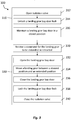
- Figure 2 is a flow diagram showing an example of a method 200 according an embodiment of the present invention.
- the method 200 of this embodiment comprises: on the basis of a status of the aircraft, causing 210 performance of only a first portion of a process for extending or retracting the landing gear; and then receiving 220 a command for the landing gear to be extended or retracted.
- the method 200 comprises maintaining a closed state of a landing gear bay door until after receiving 220 the command.
- the first portion of the process involves the use of avionics of the aircraft.
- the method 200 may be performed by a landing gear controller, such as the landing gear controller 120 of any one of the embodiments discussed above.
- the command may be received at the landing gear controller from aircraft cockpit controls of the aircraft.
- Figure 3 is a flow diagram showing an example of another method 300 to extend or retract a landing gear of an aircraft during an aircraft take-off or landing procedure, according an embodiment of the present invention.
- the method 300 of this embodiment comprises: on the basis of a status of the aircraft, causing 310 performance of only a first portion 310 of a process for extending or retracting the landing gear, then receiving 320 a command for the landing gear to be extended or retracted, and then, on the basis of the command, causing 330 performance of a second portion of the process for extending or retracting the landing gear.
- the method 300 may be performed by a landing gear controller, such as the landing gear controller 120 of any one of the embodiments discussed above, and the command may be received at the landing gear controller from aircraft cockpit controls of the aircraft.
- the first portion of the process for extending or retracting the landing gear comprises the following operations: operating 312 an isolator (such as opening the isolation valve 160 discussed above), unlocking 314 a landing gear bay door lock (such as the lock 140 discussed above), and maintaining 316 a landing gear bay door (such as the door 130 discussed above) in a closed position.
- These operations 312, 314, 316 may be carried out in the order presented.
- the first portion of the process may comprise only one, or a combination of some, of these operations 312, 314, 316.
- the second portion of the process for extending or retracting the landing gear comprises the following operations: opening 332 the landing gear bay door, moving 334 the landing gear between a stowed position and an extended position, closing 336 the landing gear bay door, locking 338 the landing gear bay door lock to retain the landing gear bay door in a closed position, and operating 340 the isolator (such as closing the isolation valve 160 discussed above).
- These operations 332, 334, 336, 338, 340 may be carried out in the order presented.
- the second portion of the process may comprise only one, or a combination of some, of these operations 332, 334, 336, 338, 340.
- Either of the methods 200, 300 described above with reference to Figure 2 and Figure 3 , respectively, may be implemented by one of the aircraft landing gear systems described above, such as system 100 illustrated in Figure 1 .
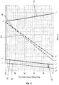
- Figure 4 shows a graph that demonstrates the time saved in extending or retracting a landing gear by implementation of an embodiment of the present invention, as compared to a comparative example.
- a pilot requested extension or retraction of the landing gear at time To by generating a command for the landing gear to be extended or retracted.
- opening of a landing gear bay door is started in response to the command at time T 1 and completed at time T 2 , as denoted by line 12.
- extension or retraction of the landing gear is started at time T 3 and completed at time T 4 , as denoted by line 14.
- Closing of the landing gear bay door is started after the landing gear has reached the respective extended or stowed position, and the landing gear bay door is fully closed at time T 5 , as denoted by line 16.
- extending or retracting the landing gear in response to the command takes time T 5 from time T 0 , in this comparative example.
- the pilot generates a command to extend or retract the landing gear at time T 0 . Since a first portion of the landing gear extension or retraction process has been performed before time T 0 , opening the landing gear bay door in response to the command is started earlier than in the comparative example. That is, in this embodiment, opening of the landing gear bay door is started at time T 1 ' and completed at time T 2 ', as denoted by line 13. Time T 1 ' is closer to time T 0 than time T 1 by an amount of time saved 10. In this embodiment, the time taken to move the landing gear bay door from a closed position to an open position is the same as in the comparative example.
- time T 2 ' is also closer to time T 0 than time T 2 by the amount of time saved 10.
- extension or retraction of the landing gear is started at time T 3 ' and completed at time T 4 ', as denoted by line 15.
- Closing of the landing gear bay door is started after the landing gear has reached the respective extended or stowed position, and the landing gear bay door is fully closed at time T 5 ', as denoted by line 17.
- each movement of the landing gear bay door and the landing gear within the landing gear extension or retraction process is therefore started and completed earlier than in the comparative example by the amount of time saved 10, as denoted by lines 15 and 17 of Figure 4 .
- extending or retracting the landing gear in response to the command takes time T 5 ' from time T 0 , in this embodiment, which is a shorter period of time than the time required in the comparative example by the amount of time saved 10.
- a landing gear is moved to a stowed position in a shorter period of time from when a pilot commands the landing gear to be retracted, as compared to a comparative example. This can help to improve the climb performance of the aircraft, which in turn can help to allow an increase in the maximum take-off weight of the aircraft, as discussed above.
- the present invention can be implemented to allow a slower extension or retraction of the landing gear, whilst taking the same overall time T 5 to deploy or stow the landing gear in response to a command as in a comparative example, as shown by way of example in Figure 5 .
- the comparative example shown in Figure 5 is the same as the comparative example shown in Figure 4 and described with reference to Figure 4 .
- the pilot generates a command to extend or retract the landing gear at time T 0 . Since a first portion of the landing gear extension or retraction process has been performed before time T 0 , opening the landing gear bay door in response to the command is started earlier than in the comparative example. That is, in this embodiment, opening the landing gear bay door is started at time T 1 ' and completed at time T 2 ', as denoted by line 23. Time T 1 ' is closer to time T 0 than time T 1 by an amount of time saved 10. The time taken to move the landing gear bay door from a closed position to an open position is the same in the comparative example and in this embodiment.
- time T 2 ' is also closer to time To than time T 2 by the amount of time saved 10.
- extension or retraction of the landing gear is started at time T 3 ' and completed at time T 4 , as denoted by line 25. That is, extending or retracting the landing gear in this embodiment takes a longer period of time than in the comparative example, by the amount of time saved 10. In other embodiments, extending or retracting the landing gear may take a longer period of time than in the comparative example, and yet there may still be time saved in completing the overall process as measured from time T 0 .
- closing of the landing gear bay door is started after the landing gear has reached the respective extended or stowed position, and the landing gear bay door is fully closed at time T 5 , as denoted by line 16.
- the full process of deploying or stowing the landing gear in response to the command takes time T 5 from time T 0 in both this embodiment and in the comparative example.
- permitting the extending or retracting of the landing gear to take a longer period of time than in the comparative example can help to reduce the demand on the landing gear extension and retraction system that is used to move the landing gear. Additionally or alternatively, this can help to reduce the demand on a power source that powers the landing gear extension and retraction system that is used to move the landing gear.
- embodiments of the present invention potentially allow a smaller and/or lighter landing gear extension and retraction system and/or power system to be provided on the aircraft.
- a similar principle could be applied to reduce the speed of movement of the landing gear bay door between the open position and the closed position.
- FIG. 6 shows a schematic diagram of a non-transitory computer-readable storage medium 400 according to an embodiment of the present invention.
- the non-transitory computer-readable storage medium 400 stores instructions 430 that, if executed by a processor 420 of a controller 410, cause the processor 420 to perform a method according to an embodiment of the present invention.
- the controller 410 is the landing gear controller 120 as described above with reference to Figure 1 .
- the instructions 430 comprise: on the basis of a status of an aircraft, causing 432 performance of only a first portion of a process for extending or retracting a landing gear, and then receiving 434 a command for the landing gear to be extended or retracted.
- the instructions 430 may comprise instructions to perform the operations of one of the methods 200, 300 described above with reference to Figure 2 and Figure 3 , respectively.
- Figure 7 shows a schematic diagram of an aircraft 500 in accordance with an embodiment of the present invention.
- the aircraft 500 comprises two main landing gears 510 and a nose landing gear 520.
- the aircraft 500 also comprises the non-transitory computer-readable storage medium 400 (not shown) discussed above with reference to Figure 6 .
- the aircraft 500 also comprises the landing gear system 100 (not shown) discussed above with reference to Figure 1 .
- the landing gear system 100 is common to all of the landing gears 510, 520.
- the aircraft 500 has a plurality of the landing gear systems 100, such as one for each of the landing gears 510, 520.
- the aircraft 500 also has a power supply (not shown) to which the landing gear extension and retraction system 110 of the landing gear system 100 may be selectively connected by appropriate operation of the isolator, as discussed above.
Landscapes
- Engineering & Computer Science (AREA)
- Mechanical Engineering (AREA)
- Aviation & Aerospace Engineering (AREA)
- Physics & Mathematics (AREA)
- General Physics & Mathematics (AREA)
- Automation & Control Theory (AREA)
- Gear Transmission (AREA)
- Traffic Control Systems (AREA)
Applications Claiming Priority (1)
| Application Number | Priority Date | Filing Date | Title |
|---|---|---|---|
| GB1709609.0A GB2563437A (en) | 2017-06-16 | 2017-06-16 | Landing gear controller |
Publications (2)
| Publication Number | Publication Date |
|---|---|
| EP3415419A1 true EP3415419A1 (de) | 2018-12-19 |
| EP3415419B1 EP3415419B1 (de) | 2023-08-02 |
Family
ID=59462282
Family Applications (1)
| Application Number | Title | Priority Date | Filing Date |
|---|---|---|---|
| EP18177930.7A Active EP3415419B1 (de) | 2017-06-16 | 2018-06-15 | Fahrwerksregler |
Country Status (4)
| Country | Link |
|---|---|
| US (2) | US11345464B2 (de) |
| EP (1) | EP3415419B1 (de) |
| CN (1) | CN109131845B (de) |
| GB (1) | GB2563437A (de) |
Cited By (4)
| Publication number | Priority date | Publication date | Assignee | Title |
|---|---|---|---|---|
| EP3702270A1 (de) * | 2019-02-28 | 2020-09-02 | Airbus Operations Limited | Einfahren des fahrwerks |
| EP3689740A3 (de) * | 2019-01-31 | 2020-12-16 | Airbus Operations Limited | Fahrwerkseinsatz |
| GB2587205A (en) * | 2019-09-17 | 2021-03-24 | Airbus Operations Ltd | Aircraft system |
| US12060147B2 (en) | 2021-04-26 | 2024-08-13 | Airbus Operations Limited | Retraction alert for aircraft landing gear |
Families Citing this family (15)
| Publication number | Priority date | Publication date | Assignee | Title |
|---|---|---|---|---|
| GB2563437A (en) * | 2017-06-16 | 2018-12-19 | Airbus Operations Ltd | Landing gear controller |
| US10266253B1 (en) * | 2017-11-10 | 2019-04-23 | The Boeing Company | Methods and apparatus for controlling landing gear shrink |
| US11358710B2 (en) * | 2018-02-23 | 2022-06-14 | The Boeing Company | Methods and apparatus for controlling landing gear retract braking |
| US10933982B2 (en) | 2018-02-26 | 2021-03-02 | The Boeing Company | Methods and apparatus for controlling landing gear retract braking |
| GB2581824A (en) * | 2019-02-28 | 2020-09-02 | Airbus Operations Ltd | Landing gear control |
| CN111661314B (zh) * | 2019-03-07 | 2023-07-14 | 海鹰航空通用装备有限责任公司 | 无人机起落架自主收起管理方法及控制系统 |
| GB2582151B (en) * | 2019-03-12 | 2021-10-13 | Airbus Operations Ltd | Landing gear system uplock arrangement |
| GB2583464A (en) * | 2019-04-18 | 2020-11-04 | Airbus Operations Ltd | System and method for landing gear retraction |
| GB2585065A (en) | 2019-06-27 | 2020-12-30 | Airbus Operations Ltd | Controlling movement of landing gear or landing gear bay doors |
| GB2604183A (en) | 2021-02-26 | 2022-08-31 | Airbus Operations Ltd | Aircraft system |
| GB2604180A (en) * | 2021-02-26 | 2022-08-31 | Airbus Operations Ltd | Aircraft system |
| GB2604182A (en) | 2021-02-26 | 2022-08-31 | Airbus Operations Ltd | Aircraft system |
| FR3122167B1 (fr) * | 2021-04-26 | 2025-08-01 | Airbus Sas | Procede et systeme d’aide au pilotage d’un aeronef et aeronef |
| GB2606205A (en) * | 2021-04-29 | 2022-11-02 | Airbus Operations Ltd | Aircraft braking controller and system |
| FR3126692B1 (fr) * | 2021-09-09 | 2025-08-15 | Safran Landing Systems | Procédé et dispositif de déverrouillage d’une trappe d’un atterrisseur d’aéronef |
Citations (2)
| Publication number | Priority date | Publication date | Assignee | Title |
|---|---|---|---|---|
| US6854689B1 (en) * | 2004-02-09 | 2005-02-15 | The Boeing Company | Methods and systems for operating aircraft landing gears |
| US20080035790A1 (en) * | 2006-08-11 | 2008-02-14 | Bryant Malcolm S | Aircraft landing gear truck orientation for noise reduction |
Family Cites Families (16)
| Publication number | Priority date | Publication date | Assignee | Title |
|---|---|---|---|---|
| US6129306A (en) * | 1997-03-05 | 2000-10-10 | Pham; Roger N. C. | Easily-convertible high-performance roadable aircraft |
| CA2390487C (en) * | 2001-06-11 | 2009-02-10 | Robert D. Wiplinger | Gear status indicator aircraft landing system |
| FR2875475B1 (fr) * | 2004-09-21 | 2008-02-08 | Airbus France Sas | Systeme de manoeuvre d'un train d'atterrissage pour aeronef et aeronef comportant un tel systeme |
| FR2887516B1 (fr) * | 2005-06-27 | 2008-10-03 | Messier Bugatti Sa | Architecture distribuee de systeme de gestion d'atterisseurs d'aeronef |
| FR2898866B1 (fr) * | 2006-03-22 | 2008-11-21 | Airbus France Sas | Distributeur hydraulique pour train d'atterrissage d'avion |
| US8684306B2 (en) * | 2011-01-26 | 2014-04-01 | Goodrich Corporation | Steering collar locking mechanism for retractable aircraft nose landing gear |
| US8463462B2 (en) * | 2011-09-02 | 2013-06-11 | Goodrich Corporation | Systems and methods for braking system testing |
| FR2981910B1 (fr) * | 2011-10-26 | 2013-12-27 | Eurocopter France | Atterrisseur, aeronef et procede |
| FR2982240B1 (fr) * | 2011-11-09 | 2013-12-13 | Messier Bugatti Dowty | Procede de deploiement d'atterrisseurs d'aeronef en mode secours. |
| FR3001708B1 (fr) * | 2013-02-06 | 2015-02-13 | Eurocopter France | Train d'atterrissage retractable, aeronef muni dudit train d'atterrissage, et procede de manoeuvre dudit train d'atterrissage |
| US10106248B2 (en) * | 2013-06-14 | 2018-10-23 | Bombardier Inc. | Apparatus and method for controlling landing gear |
| US20150122945A1 (en) * | 2013-11-03 | 2015-05-07 | Peter Apostolos Kavounas | Passenger aircraft with automatically deployable and/or retractable landing gear |
| FR3013681B1 (fr) * | 2013-11-22 | 2017-06-09 | Messier Bugatti Dowty | Procede pour diminuer le temps de manoeuvre apparent d'atterrisseurs d'un aeronef. |
| US9709102B2 (en) | 2015-06-15 | 2017-07-18 | GM Global Technology Operations LLC | Transmission for a powertrain system |
| ES2668445T3 (es) * | 2015-06-15 | 2018-05-18 | Airbus Operations, S.L. | Procedimiento de operación de un sistema de tren de aterrizaje |
| GB2563437A (en) * | 2017-06-16 | 2018-12-19 | Airbus Operations Ltd | Landing gear controller |
-
2017
- 2017-06-16 GB GB1709609.0A patent/GB2563437A/en not_active Withdrawn
-
2018
- 2018-06-15 CN CN201810618970.6A patent/CN109131845B/zh active Active
- 2018-06-15 US US16/009,470 patent/US11345464B2/en active Active
- 2018-06-15 EP EP18177930.7A patent/EP3415419B1/de active Active
-
2022
- 2022-05-04 US US17/736,787 patent/US11753151B2/en active Active
Patent Citations (2)
| Publication number | Priority date | Publication date | Assignee | Title |
|---|---|---|---|---|
| US6854689B1 (en) * | 2004-02-09 | 2005-02-15 | The Boeing Company | Methods and systems for operating aircraft landing gears |
| US20080035790A1 (en) * | 2006-08-11 | 2008-02-14 | Bryant Malcolm S | Aircraft landing gear truck orientation for noise reduction |
Cited By (12)
| Publication number | Priority date | Publication date | Assignee | Title |
|---|---|---|---|---|
| EP3689740A3 (de) * | 2019-01-31 | 2020-12-16 | Airbus Operations Limited | Fahrwerkseinsatz |
| US11531356B2 (en) | 2019-01-31 | 2022-12-20 | Airbus Operations Limited | Landing gear deployment |
| US11880211B2 (en) | 2019-01-31 | 2024-01-23 | Airbus Operations Limited | Landing gear deployment |
| EP3702270A1 (de) * | 2019-02-28 | 2020-09-02 | Airbus Operations Limited | Einfahren des fahrwerks |
| GB2581825A (en) * | 2019-02-28 | 2020-09-02 | Airbus Operations Ltd | Landing gear retraction |
| CN111619790A (zh) * | 2019-02-28 | 2020-09-04 | 空中客车营运有限公司 | 起落架系统、飞行器及方法与存储介质 |
| US11541992B2 (en) | 2019-02-28 | 2023-01-03 | Airbus Operations Limited | Landing gear retraction |
| CN111619790B (zh) * | 2019-02-28 | 2024-12-03 | 空中客车营运有限公司 | 起落架系统、飞行器及方法与存储介质 |
| GB2587205A (en) * | 2019-09-17 | 2021-03-24 | Airbus Operations Ltd | Aircraft system |
| WO2021053021A1 (en) * | 2019-09-17 | 2021-03-25 | Airbus Operations Limited | Aircraft system |
| US12214866B2 (en) | 2019-09-17 | 2025-02-04 | Airbus Operations Limited | Aircraft take-off system |
| US12060147B2 (en) | 2021-04-26 | 2024-08-13 | Airbus Operations Limited | Retraction alert for aircraft landing gear |
Also Published As
| Publication number | Publication date |
|---|---|
| US11345464B2 (en) | 2022-05-31 |
| EP3415419B1 (de) | 2023-08-02 |
| CN109131845B (zh) | 2023-08-22 |
| US20180362151A1 (en) | 2018-12-20 |
| GB2563437A (en) | 2018-12-19 |
| US11753151B2 (en) | 2023-09-12 |
| US20220258854A1 (en) | 2022-08-18 |
| GB201709609D0 (en) | 2017-08-02 |
| CN109131845A (zh) | 2019-01-04 |
Similar Documents
| Publication | Publication Date | Title |
|---|---|---|
| US11753151B2 (en) | Landing gear controller | |
| CN111619790B (zh) | 起落架系统、飞行器及方法与存储介质 | |
| CN113200142B (zh) | 起落架系统控制 | |
| US9573676B2 (en) | Device for an adjustable flap of a wing | |
| CN111824396B (zh) | 用于起落架收回的系统及方法 | |
| US10894598B2 (en) | Landing gear controller | |
| CN113508079B (zh) | 对起落架运动或起落架舱门的运动的控制 | |
| US20160362177A1 (en) | Method for operating a landing gear system | |
| EP4049928B1 (de) | Flugzeugsystem | |
| EP4049926B1 (de) | Flugzeugsystem | |
| EP4552975A1 (de) | Fahrwerksteuerung |
Legal Events
| Date | Code | Title | Description |
|---|---|---|---|
| PUAI | Public reference made under article 153(3) epc to a published international application that has entered the european phase |
Free format text: ORIGINAL CODE: 0009012 |
|
| STAA | Information on the status of an ep patent application or granted ep patent |
Free format text: STATUS: THE APPLICATION HAS BEEN PUBLISHED |
|
| AK | Designated contracting states |
Kind code of ref document: A1 Designated state(s): AL AT BE BG CH CY CZ DE DK EE ES FI FR GB GR HR HU IE IS IT LI LT LU LV MC MK MT NL NO PL PT RO RS SE SI SK SM TR |
|
| AX | Request for extension of the european patent |
Extension state: BA ME |
|
| STAA | Information on the status of an ep patent application or granted ep patent |
Free format text: STATUS: REQUEST FOR EXAMINATION WAS MADE |
|
| 17P | Request for examination filed |
Effective date: 20190619 |
|
| RBV | Designated contracting states (corrected) |
Designated state(s): AL AT BE BG CH CY CZ DE DK EE ES FI FR GB GR HR HU IE IS IT LI LT LU LV MC MK MT NL NO PL PT RO RS SE SI SK SM TR |
|
| STAA | Information on the status of an ep patent application or granted ep patent |
Free format text: STATUS: EXAMINATION IS IN PROGRESS |
|
| 17Q | First examination report despatched |
Effective date: 20201009 |
|
| GRAP | Despatch of communication of intention to grant a patent |
Free format text: ORIGINAL CODE: EPIDOSNIGR1 |
|
| STAA | Information on the status of an ep patent application or granted ep patent |
Free format text: STATUS: GRANT OF PATENT IS INTENDED |
|
| INTG | Intention to grant announced |
Effective date: 20230223 |
|
| GRAS | Grant fee paid |
Free format text: ORIGINAL CODE: EPIDOSNIGR3 |
|
| GRAA | (expected) grant |
Free format text: ORIGINAL CODE: 0009210 |
|
| STAA | Information on the status of an ep patent application or granted ep patent |
Free format text: STATUS: THE PATENT HAS BEEN GRANTED |
|
| AK | Designated contracting states |
Kind code of ref document: B1 Designated state(s): AL AT BE BG CH CY CZ DE DK EE ES FI FR GB GR HR HU IE IS IT LI LT LU LV MC MK MT NL NO PL PT RO RS SE SI SK SM TR |
|
| REG | Reference to a national code |
Ref country code: GB Ref legal event code: FG4D |
|
| REG | Reference to a national code |
Ref country code: CH Ref legal event code: EP |
|
| REG | Reference to a national code |
Ref country code: DE Ref legal event code: R096 Ref document number: 602018054403 Country of ref document: DE |
|
| REG | Reference to a national code |
Ref country code: IE Ref legal event code: FG4D |
|
| REG | Reference to a national code |
Ref country code: LT Ref legal event code: MG9D |
|
| REG | Reference to a national code |
Ref country code: NL Ref legal event code: MP Effective date: 20230802 |
|
| REG | Reference to a national code |
Ref country code: AT Ref legal event code: MK05 Ref document number: 1594463 Country of ref document: AT Kind code of ref document: T Effective date: 20230802 |
|
| PG25 | Lapsed in a contracting state [announced via postgrant information from national office to epo] |
Ref country code: GR Free format text: LAPSE BECAUSE OF FAILURE TO SUBMIT A TRANSLATION OF THE DESCRIPTION OR TO PAY THE FEE WITHIN THE PRESCRIBED TIME-LIMIT Effective date: 20231103 |
|
| PG25 | Lapsed in a contracting state [announced via postgrant information from national office to epo] |
Ref country code: IS Free format text: LAPSE BECAUSE OF FAILURE TO SUBMIT A TRANSLATION OF THE DESCRIPTION OR TO PAY THE FEE WITHIN THE PRESCRIBED TIME-LIMIT Effective date: 20231202 |
|
| PG25 | Lapsed in a contracting state [announced via postgrant information from national office to epo] |
Ref country code: SE Free format text: LAPSE BECAUSE OF FAILURE TO SUBMIT A TRANSLATION OF THE DESCRIPTION OR TO PAY THE FEE WITHIN THE PRESCRIBED TIME-LIMIT Effective date: 20230802 Ref country code: RS Free format text: LAPSE BECAUSE OF FAILURE TO SUBMIT A TRANSLATION OF THE DESCRIPTION OR TO PAY THE FEE WITHIN THE PRESCRIBED TIME-LIMIT Effective date: 20230802 Ref country code: PT Free format text: LAPSE BECAUSE OF FAILURE TO SUBMIT A TRANSLATION OF THE DESCRIPTION OR TO PAY THE FEE WITHIN THE PRESCRIBED TIME-LIMIT Effective date: 20231204 Ref country code: NO Free format text: LAPSE BECAUSE OF FAILURE TO SUBMIT A TRANSLATION OF THE DESCRIPTION OR TO PAY THE FEE WITHIN THE PRESCRIBED TIME-LIMIT Effective date: 20231102 Ref country code: NL Free format text: LAPSE BECAUSE OF FAILURE TO SUBMIT A TRANSLATION OF THE DESCRIPTION OR TO PAY THE FEE WITHIN THE PRESCRIBED TIME-LIMIT Effective date: 20230802 Ref country code: LV Free format text: LAPSE BECAUSE OF FAILURE TO SUBMIT A TRANSLATION OF THE DESCRIPTION OR TO PAY THE FEE WITHIN THE PRESCRIBED TIME-LIMIT Effective date: 20230802 Ref country code: LT Free format text: LAPSE BECAUSE OF FAILURE TO SUBMIT A TRANSLATION OF THE DESCRIPTION OR TO PAY THE FEE WITHIN THE PRESCRIBED TIME-LIMIT Effective date: 20230802 Ref country code: IS Free format text: LAPSE BECAUSE OF FAILURE TO SUBMIT A TRANSLATION OF THE DESCRIPTION OR TO PAY THE FEE WITHIN THE PRESCRIBED TIME-LIMIT Effective date: 20231202 Ref country code: HR Free format text: LAPSE BECAUSE OF FAILURE TO SUBMIT A TRANSLATION OF THE DESCRIPTION OR TO PAY THE FEE WITHIN THE PRESCRIBED TIME-LIMIT Effective date: 20230802 Ref country code: GR Free format text: LAPSE BECAUSE OF FAILURE TO SUBMIT A TRANSLATION OF THE DESCRIPTION OR TO PAY THE FEE WITHIN THE PRESCRIBED TIME-LIMIT Effective date: 20231103 Ref country code: FI Free format text: LAPSE BECAUSE OF FAILURE TO SUBMIT A TRANSLATION OF THE DESCRIPTION OR TO PAY THE FEE WITHIN THE PRESCRIBED TIME-LIMIT Effective date: 20230802 Ref country code: AT Free format text: LAPSE BECAUSE OF FAILURE TO SUBMIT A TRANSLATION OF THE DESCRIPTION OR TO PAY THE FEE WITHIN THE PRESCRIBED TIME-LIMIT Effective date: 20230802 |
|
| PG25 | Lapsed in a contracting state [announced via postgrant information from national office to epo] |
Ref country code: PL Free format text: LAPSE BECAUSE OF FAILURE TO SUBMIT A TRANSLATION OF THE DESCRIPTION OR TO PAY THE FEE WITHIN THE PRESCRIBED TIME-LIMIT Effective date: 20230802 |
|
| PG25 | Lapsed in a contracting state [announced via postgrant information from national office to epo] |
Ref country code: ES Free format text: LAPSE BECAUSE OF FAILURE TO SUBMIT A TRANSLATION OF THE DESCRIPTION OR TO PAY THE FEE WITHIN THE PRESCRIBED TIME-LIMIT Effective date: 20230802 |
|
| PG25 | Lapsed in a contracting state [announced via postgrant information from national office to epo] |
Ref country code: SM Free format text: LAPSE BECAUSE OF FAILURE TO SUBMIT A TRANSLATION OF THE DESCRIPTION OR TO PAY THE FEE WITHIN THE PRESCRIBED TIME-LIMIT Effective date: 20230802 Ref country code: RO Free format text: LAPSE BECAUSE OF FAILURE TO SUBMIT A TRANSLATION OF THE DESCRIPTION OR TO PAY THE FEE WITHIN THE PRESCRIBED TIME-LIMIT Effective date: 20230802 Ref country code: ES Free format text: LAPSE BECAUSE OF FAILURE TO SUBMIT A TRANSLATION OF THE DESCRIPTION OR TO PAY THE FEE WITHIN THE PRESCRIBED TIME-LIMIT Effective date: 20230802 Ref country code: EE Free format text: LAPSE BECAUSE OF FAILURE TO SUBMIT A TRANSLATION OF THE DESCRIPTION OR TO PAY THE FEE WITHIN THE PRESCRIBED TIME-LIMIT Effective date: 20230802 Ref country code: DK Free format text: LAPSE BECAUSE OF FAILURE TO SUBMIT A TRANSLATION OF THE DESCRIPTION OR TO PAY THE FEE WITHIN THE PRESCRIBED TIME-LIMIT Effective date: 20230802 Ref country code: CZ Free format text: LAPSE BECAUSE OF FAILURE TO SUBMIT A TRANSLATION OF THE DESCRIPTION OR TO PAY THE FEE WITHIN THE PRESCRIBED TIME-LIMIT Effective date: 20230802 Ref country code: SK Free format text: LAPSE BECAUSE OF FAILURE TO SUBMIT A TRANSLATION OF THE DESCRIPTION OR TO PAY THE FEE WITHIN THE PRESCRIBED TIME-LIMIT Effective date: 20230802 |
|
| REG | Reference to a national code |
Ref country code: DE Ref legal event code: R097 Ref document number: 602018054403 Country of ref document: DE |
|
| PG25 | Lapsed in a contracting state [announced via postgrant information from national office to epo] |
Ref country code: IT Free format text: LAPSE BECAUSE OF FAILURE TO SUBMIT A TRANSLATION OF THE DESCRIPTION OR TO PAY THE FEE WITHIN THE PRESCRIBED TIME-LIMIT Effective date: 20230802 |
|
| PLBE | No opposition filed within time limit |
Free format text: ORIGINAL CODE: 0009261 |
|
| STAA | Information on the status of an ep patent application or granted ep patent |
Free format text: STATUS: NO OPPOSITION FILED WITHIN TIME LIMIT |
|
| 26N | No opposition filed |
Effective date: 20240503 |
|
| PG25 | Lapsed in a contracting state [announced via postgrant information from national office to epo] |
Ref country code: SI Free format text: LAPSE BECAUSE OF FAILURE TO SUBMIT A TRANSLATION OF THE DESCRIPTION OR TO PAY THE FEE WITHIN THE PRESCRIBED TIME-LIMIT Effective date: 20230802 |
|
| PG25 | Lapsed in a contracting state [announced via postgrant information from national office to epo] |
Ref country code: BG Free format text: LAPSE BECAUSE OF FAILURE TO SUBMIT A TRANSLATION OF THE DESCRIPTION OR TO PAY THE FEE WITHIN THE PRESCRIBED TIME-LIMIT Effective date: 20230802 |
|
| PG25 | Lapsed in a contracting state [announced via postgrant information from national office to epo] |
Ref country code: BG Free format text: LAPSE BECAUSE OF FAILURE TO SUBMIT A TRANSLATION OF THE DESCRIPTION OR TO PAY THE FEE WITHIN THE PRESCRIBED TIME-LIMIT Effective date: 20230802 |
|
| PG25 | Lapsed in a contracting state [announced via postgrant information from national office to epo] |
Ref country code: MC Free format text: LAPSE BECAUSE OF FAILURE TO SUBMIT A TRANSLATION OF THE DESCRIPTION OR TO PAY THE FEE WITHIN THE PRESCRIBED TIME-LIMIT Effective date: 20230802 |
|
| REG | Reference to a national code |
Ref country code: CH Ref legal event code: PL |
|
| PG25 | Lapsed in a contracting state [announced via postgrant information from national office to epo] |
Ref country code: LU Free format text: LAPSE BECAUSE OF NON-PAYMENT OF DUE FEES Effective date: 20240615 |
|
| PG25 | Lapsed in a contracting state [announced via postgrant information from national office to epo] |
Ref country code: IE Free format text: LAPSE BECAUSE OF NON-PAYMENT OF DUE FEES Effective date: 20240615 |
|
| PG25 | Lapsed in a contracting state [announced via postgrant information from national office to epo] |
Ref country code: BE Free format text: LAPSE BECAUSE OF NON-PAYMENT OF DUE FEES Effective date: 20240630 Ref country code: CH Free format text: LAPSE BECAUSE OF NON-PAYMENT OF DUE FEES Effective date: 20240630 |
|
| REG | Reference to a national code |
Ref country code: BE Ref legal event code: MM Effective date: 20240630 |
|
| PGFP | Annual fee paid to national office [announced via postgrant information from national office to epo] |
Ref country code: DE Payment date: 20250618 Year of fee payment: 8 |
|
| PGFP | Annual fee paid to national office [announced via postgrant information from national office to epo] |
Ref country code: GB Payment date: 20250618 Year of fee payment: 8 |
|
| PGFP | Annual fee paid to national office [announced via postgrant information from national office to epo] |
Ref country code: FR Payment date: 20250625 Year of fee payment: 8 |
|
| PG25 | Lapsed in a contracting state [announced via postgrant information from national office to epo] |
Ref country code: CY Free format text: LAPSE BECAUSE OF FAILURE TO SUBMIT A TRANSLATION OF THE DESCRIPTION OR TO PAY THE FEE WITHIN THE PRESCRIBED TIME-LIMIT; INVALID AB INITIO Effective date: 20180615 |
|
| PG25 | Lapsed in a contracting state [announced via postgrant information from national office to epo] |
Ref country code: HU Free format text: LAPSE BECAUSE OF FAILURE TO SUBMIT A TRANSLATION OF THE DESCRIPTION OR TO PAY THE FEE WITHIN THE PRESCRIBED TIME-LIMIT; INVALID AB INITIO Effective date: 20180615 |