EP3415438A1 - Système de propulsion hybride-électrique pour un aéronef - Google Patents
Système de propulsion hybride-électrique pour un aéronef Download PDFInfo
- Publication number
- EP3415438A1 EP3415438A1 EP18177534.7A EP18177534A EP3415438A1 EP 3415438 A1 EP3415438 A1 EP 3415438A1 EP 18177534 A EP18177534 A EP 18177534A EP 3415438 A1 EP3415438 A1 EP 3415438A1
- Authority
- EP
- European Patent Office
- Prior art keywords
- computing devices
- gas turbine
- turbine engine
- data indicative
- amount
- Prior art date
- Legal status (The legal status is an assumption and is not a legal conclusion. Google has not performed a legal analysis and makes no representation as to the accuracy of the status listed.)
- Granted
Links
Images



Classifications
-
- B—PERFORMING OPERATIONS; TRANSPORTING
- B64—AIRCRAFT; AVIATION; COSMONAUTICS
- B64D—EQUIPMENT FOR FITTING IN OR TO AIRCRAFT; FLIGHT SUITS; PARACHUTES; ARRANGEMENT OR MOUNTING OF POWER PLANTS OR PROPULSION TRANSMISSIONS IN AIRCRAFT
- B64D31/00—Power plant control systems; Arrangement of power plant control systems in aircraft
- B64D31/16—Power plant control systems; Arrangement of power plant control systems in aircraft for electric power plants
- B64D31/18—Power plant control systems; Arrangement of power plant control systems in aircraft for electric power plants for hybrid-electric power plants
-
- F—MECHANICAL ENGINEERING; LIGHTING; HEATING; WEAPONS; BLASTING
- F02—COMBUSTION ENGINES; HOT-GAS OR COMBUSTION-PRODUCT ENGINE PLANTS
- F02C—GAS-TURBINE PLANTS; AIR INTAKES FOR JET-PROPULSION PLANTS; CONTROLLING FUEL SUPPLY IN AIR-BREATHING JET-PROPULSION PLANTS
- F02C9/00—Controlling gas-turbine plants; Controlling fuel supply in air- breathing jet-propulsion plants
- F02C9/48—Control of fuel supply conjointly with another control of the plant
-
- G—PHYSICS
- G07—CHECKING-DEVICES
- G07C—TIME OR ATTENDANCE REGISTERS; REGISTERING OR INDICATING THE WORKING OF MACHINES; GENERATING RANDOM NUMBERS; VOTING OR LOTTERY APPARATUS; ARRANGEMENTS, SYSTEMS OR APPARATUS FOR CHECKING NOT PROVIDED FOR ELSEWHERE
- G07C5/00—Registering or indicating the working of vehicles
- G07C5/08—Registering or indicating performance data other than driving, working, idle, or waiting time, with or without registering driving, working, idle or waiting time
- G07C5/0808—Diagnosing performance data
-
- B—PERFORMING OPERATIONS; TRANSPORTING
- B64—AIRCRAFT; AVIATION; COSMONAUTICS
- B64D—EQUIPMENT FOR FITTING IN OR TO AIRCRAFT; FLIGHT SUITS; PARACHUTES; ARRANGEMENT OR MOUNTING OF POWER PLANTS OR PROPULSION TRANSMISSIONS IN AIRCRAFT
- B64D27/00—Arrangement or mounting of power plants in aircraft; Aircraft characterised by the type or position of power plants
- B64D27/02—Aircraft characterised by the type or position of power plants
- B64D27/026—Aircraft characterised by the type or position of power plants comprising different types of power plants, e.g. combination of a piston engine and a gas-turbine
-
- B—PERFORMING OPERATIONS; TRANSPORTING
- B64—AIRCRAFT; AVIATION; COSMONAUTICS
- B64D—EQUIPMENT FOR FITTING IN OR TO AIRCRAFT; FLIGHT SUITS; PARACHUTES; ARRANGEMENT OR MOUNTING OF POWER PLANTS OR PROPULSION TRANSMISSIONS IN AIRCRAFT
- B64D27/00—Arrangement or mounting of power plants in aircraft; Aircraft characterised by the type or position of power plants
- B64D27/02—Aircraft characterised by the type or position of power plants
- B64D27/10—Aircraft characterised by the type or position of power plants of gas-turbine type
-
- B—PERFORMING OPERATIONS; TRANSPORTING
- B64—AIRCRAFT; AVIATION; COSMONAUTICS
- B64D—EQUIPMENT FOR FITTING IN OR TO AIRCRAFT; FLIGHT SUITS; PARACHUTES; ARRANGEMENT OR MOUNTING OF POWER PLANTS OR PROPULSION TRANSMISSIONS IN AIRCRAFT
- B64D27/00—Arrangement or mounting of power plants in aircraft; Aircraft characterised by the type or position of power plants
- B64D27/02—Aircraft characterised by the type or position of power plants
- B64D27/30—Aircraft characterised by electric power plants
- B64D27/33—Hybrid electric aircraft
-
- B—PERFORMING OPERATIONS; TRANSPORTING
- B64—AIRCRAFT; AVIATION; COSMONAUTICS
- B64D—EQUIPMENT FOR FITTING IN OR TO AIRCRAFT; FLIGHT SUITS; PARACHUTES; ARRANGEMENT OR MOUNTING OF POWER PLANTS OR PROPULSION TRANSMISSIONS IN AIRCRAFT
- B64D35/00—Transmitting power from power plants to propellers or rotors; Arrangements of transmissions
- B64D35/02—Transmitting power from power plants to propellers or rotors; Arrangements of transmissions specially adapted for specific power plants
- B64D35/021—Transmitting power from power plants to propellers or rotors; Arrangements of transmissions specially adapted for specific power plants for electric power plants
- B64D35/022—Transmitting power from power plants to propellers or rotors; Arrangements of transmissions specially adapted for specific power plants for electric power plants of hybrid-electric type
- B64D35/024—Transmitting power from power plants to propellers or rotors; Arrangements of transmissions specially adapted for specific power plants for electric power plants of hybrid-electric type of series type
-
- B—PERFORMING OPERATIONS; TRANSPORTING
- B64—AIRCRAFT; AVIATION; COSMONAUTICS
- B64D—EQUIPMENT FOR FITTING IN OR TO AIRCRAFT; FLIGHT SUITS; PARACHUTES; ARRANGEMENT OR MOUNTING OF POWER PLANTS OR PROPULSION TRANSMISSIONS IN AIRCRAFT
- B64D35/00—Transmitting power from power plants to propellers or rotors; Arrangements of transmissions
- B64D35/02—Transmitting power from power plants to propellers or rotors; Arrangements of transmissions specially adapted for specific power plants
- B64D35/021—Transmitting power from power plants to propellers or rotors; Arrangements of transmissions specially adapted for specific power plants for electric power plants
- B64D35/022—Transmitting power from power plants to propellers or rotors; Arrangements of transmissions specially adapted for specific power plants for electric power plants of hybrid-electric type
- B64D35/025—Transmitting power from power plants to propellers or rotors; Arrangements of transmissions specially adapted for specific power plants for electric power plants of hybrid-electric type of parallel type
-
- F—MECHANICAL ENGINEERING; LIGHTING; HEATING; WEAPONS; BLASTING
- F02—COMBUSTION ENGINES; HOT-GAS OR COMBUSTION-PRODUCT ENGINE PLANTS
- F02C—GAS-TURBINE PLANTS; AIR INTAKES FOR JET-PROPULSION PLANTS; CONTROLLING FUEL SUPPLY IN AIR-BREATHING JET-PROPULSION PLANTS
- F02C9/00—Controlling gas-turbine plants; Controlling fuel supply in air- breathing jet-propulsion plants
-
- G—PHYSICS
- G07—CHECKING-DEVICES
- G07C—TIME OR ATTENDANCE REGISTERS; REGISTERING OR INDICATING THE WORKING OF MACHINES; GENERATING RANDOM NUMBERS; VOTING OR LOTTERY APPARATUS; ARRANGEMENTS, SYSTEMS OR APPARATUS FOR CHECKING NOT PROVIDED FOR ELSEWHERE
- G07C5/00—Registering or indicating the working of vehicles
- G07C5/08—Registering or indicating performance data other than driving, working, idle, or waiting time, with or without registering driving, working, idle or waiting time
- G07C5/0841—Registering performance data
-
- B—PERFORMING OPERATIONS; TRANSPORTING
- B64—AIRCRAFT; AVIATION; COSMONAUTICS
- B64D—EQUIPMENT FOR FITTING IN OR TO AIRCRAFT; FLIGHT SUITS; PARACHUTES; ARRANGEMENT OR MOUNTING OF POWER PLANTS OR PROPULSION TRANSMISSIONS IN AIRCRAFT
- B64D45/00—Aircraft indicators or protectors not otherwise provided for
- B64D2045/0085—Devices for aircraft health monitoring, e.g. monitoring flutter or vibration
-
- B—PERFORMING OPERATIONS; TRANSPORTING
- B64—AIRCRAFT; AVIATION; COSMONAUTICS
- B64D—EQUIPMENT FOR FITTING IN OR TO AIRCRAFT; FLIGHT SUITS; PARACHUTES; ARRANGEMENT OR MOUNTING OF POWER PLANTS OR PROPULSION TRANSMISSIONS IN AIRCRAFT
- B64D43/00—Arrangements or adaptations of instruments
-
- F—MECHANICAL ENGINEERING; LIGHTING; HEATING; WEAPONS; BLASTING
- F05—INDEXING SCHEMES RELATING TO ENGINES OR PUMPS IN VARIOUS SUBCLASSES OF CLASSES F01-F04
- F05D—INDEXING SCHEME FOR ASPECTS RELATING TO NON-POSITIVE-DISPLACEMENT MACHINES OR ENGINES, GAS-TURBINES OR JET-PROPULSION PLANTS
- F05D2220/00—Application
- F05D2220/30—Application in turbines
- F05D2220/32—Application in turbines in gas turbines
- F05D2220/323—Application in turbines in gas turbines for aircraft propulsion, e.g. jet engines
-
- F—MECHANICAL ENGINEERING; LIGHTING; HEATING; WEAPONS; BLASTING
- F05—INDEXING SCHEMES RELATING TO ENGINES OR PUMPS IN VARIOUS SUBCLASSES OF CLASSES F01-F04
- F05D—INDEXING SCHEME FOR ASPECTS RELATING TO NON-POSITIVE-DISPLACEMENT MACHINES OR ENGINES, GAS-TURBINES OR JET-PROPULSION PLANTS
- F05D2260/00—Function
- F05D2260/80—Diagnostics
-
- G—PHYSICS
- G07—CHECKING-DEVICES
- G07C—TIME OR ATTENDANCE REGISTERS; REGISTERING OR INDICATING THE WORKING OF MACHINES; GENERATING RANDOM NUMBERS; VOTING OR LOTTERY APPARATUS; ARRANGEMENTS, SYSTEMS OR APPARATUS FOR CHECKING NOT PROVIDED FOR ELSEWHERE
- G07C5/00—Registering or indicating the working of vehicles
- G07C5/08—Registering or indicating performance data other than driving, working, idle, or waiting time, with or without registering driving, working, idle or waiting time
-
- Y—GENERAL TAGGING OF NEW TECHNOLOGICAL DEVELOPMENTS; GENERAL TAGGING OF CROSS-SECTIONAL TECHNOLOGIES SPANNING OVER SEVERAL SECTIONS OF THE IPC; TECHNICAL SUBJECTS COVERED BY FORMER USPC CROSS-REFERENCE ART COLLECTIONS [XRACs] AND DIGESTS
- Y02—TECHNOLOGIES OR APPLICATIONS FOR MITIGATION OR ADAPTATION AGAINST CLIMATE CHANGE
- Y02T—CLIMATE CHANGE MITIGATION TECHNOLOGIES RELATED TO TRANSPORTATION
- Y02T50/00—Aeronautics or air transport
- Y02T50/60—Efficient propulsion technologies, e.g. for aircraft
Definitions
- the present subject matter relates generally to a hybrid-electric propulsion system for an aircraft, and more particularly to a method for assessing a health of a gas turbine engine of the hybrid-electric propulsion system.
- the engines are designed to operate for relatively long period of time. During this course of operation, the engine may degrade, reducing engine performance and efficiency, and/or increasing engine emissions. Once the engine degrades to a certain point, certain maintenance operations must be performed on the engine to bring it back to a certain operability level. These maintenance operations may include taking the engine off wing and overhauling engine. This process may be time-consuming and expensive. Therefore, it is generally desirable to wait until these maintenance operations are necessary prior to performing such maintenance operations. Accordingly, a system capable of determining an engine health of an engine and/or predicting when certain maintenance operations will be required for the engine would be useful.
- a computer-implemented method of assessing a health of a gas turbine engine of a hybrid-electric propulsion system for an aircraft includes an electric machine rotatable with the gas turbine engine.
- the method includes receiving, by one or more computing devices, data indicative of an amount of electrical power provided to, or extracted from, the electric machine.
- the method also includes receiving, by the one or more computing devices, data indicative of an operating parameter of the hybrid-electric propulsion system.
- the method also includes assessing, by the one or more computing devices, a health of the gas turbine engine based at least in part on the received data indicative of the amount of electrical power provided to, or extracted from, the electric machine and the received data indicative of the operating parameter of the hybrid electric propulsion system.
- the method also includes providing, by the one or more computing devices, information to a user indicative of the health of the gas turbine engine.
- receiving, by the one or more computing devices, data indicative of the operating parameter of the hybrid electric propulsion system includes receiving, by the one or more computing devices, data indicative of an operating parameter of the gas turbine engine.
- receiving, by the one or more computing devices, data indicative of the operating parameter of the gas turbine engine includes receiving, by the one or more computing devices, data indicative of one or more of a temperature within the gas turbine engine, a rotational speed of one or more components of the gas turbine engine, an amount of fuel provided to a combustion section of the gas turbine engine, or data indicative of a pressure within the gas turbine engine.
- receiving, by the one or more computing devices, data indicative of the amount of electrical power provided to, or extracted from, the electric machine includes receiving, by the one or more computing devices, data indicative of the amount of electrical power extracted from the electric machine.
- receiving, by the one or more computing devices, data indicative of the amount of electrical power provided to, or extracted from, the electric machine includes receiving, by the one or more computing devices, data indicative of the amount of electrical power provided to the electric machine.
- the method further includes changing, by the one or more computing devices, an amount of fuel provided to the combustion section of the gas turbine engine for an amount of time, wherein receiving, by the one or more computing devices, data indicative of the amount of electrical power provided to, or extracted from, the electric machine includes receiving, by the one or more computing devices, data indicative of a change in the amount of electrical power provided to, or extracted from, the electric machine during at least a portion of the amount of time.
- receiving, by the one or more computing devices, data indicative of the operating parameter of the hybrid-electric propulsion system includes receiving, by the one or more computing devices, data indicative of a change in a fuel flow parameter during the amount of time.
- receiving, by the one or more computing devices, data indicative of the amount of electrical power provided to, or extracted from, the electric machine includes receiving, by the one or more computing devices, data indicative of the amount of electrical power provided to, or extracted from, the electric machine over a plurality of operation cycles
- receiving, by the one or more computing devices, data indicative of the operating parameter of the hybrid-electric propulsion system includes receiving, by the one or more computing devices, data indicative of the operating parameter of the hybrid-electric propulsion system over the plurality of operation cycles
- assessing, by the one or more computing devices, the health of the gas turbine engine includes comparing, by the one or more computing devices, the received data indicative of the amount of electrical power provided to, or extracted from, the electric machine over the plurality of operation cycles and the received data indicative of the operating parameter of the hybrid-electric propulsion system over the plurality of operation cycles.
- assessing, by the one or more computing devices, the health of the gas turbine engine further includes trending, by the one or more computing devices, the compared information over a time variable or a cycle variable.
- assessing, by the one or more computing devices, the health of the gas turbine engine further includes determining, by the one or more computing devices, an amount of time, a number of cycles, or both until a maintenance operation is needed for the gas turbine engine based on the trending of the compared information over the time variable or the cycle variable.
- the method further includes modifying, by the one or more computing devices, an engine parameter indicative of a stall margin of the gas turbine engine in response to the assessment, by the one or more computing devices, of the health of the gas turbine.
- providing, by the one or more computing devices, information to the user indicative of the health of the gas turbine engine includes displaying, by the one or more computing devices, the health of the gas turbine engine on a user interface device.
- the method further includes scheduling, by the one or more computing devices, a maintenance operation for the gas turbine engine in response to assessing, by the one or more computing devices, the health of the gas turbine engine.
- a hybrid-electric propulsion system for an aircraft.
- the hybrid electric propulsion system includes an electric machine, a gas turbine engine mechanically coupled to the electric machine for driving the electric machine, and an electric propulsor assembly electrically connectable to the electric machine.
- the hybrid electric propulsion system further includes a controller including memory and one or more processors, the memory storing instructions that when executed by the one or more processors cause the hybrid-electric propulsion system to perform functions.
- the functions include receiving data indicative of an amount of electrical power provided to, or extracted from, the electric machine; receiving data indicative of an operating parameter of the hybrid-electric propulsion system; assessing a health of the gas turbine engine based at least in part on the received data indicative of the amount of electrical power provided to, or extracted from, the electric machine and the received data indicative of the operating parameter of the hybrid electric propulsion system; and providing information to a user indicative of the health of the gas turbine engine.
- receiving data indicative of the operating parameter of the hybrid electric propulsion system includes receiving data indicative of an operating parameter of the gas turbine engine.
- receiving data indicative of the operating parameter of the gas turbine engine includes receiving data indicative of one or more of a temperature within the gas turbine engine, a rotational speed of one or more components of the gas turbine engine, an amount of fuel provided to a combustion section of the gas turbine engine, or data indicative of a pressure within the gas turbine engine.
- the functions further include changing an amount of fuel provided to the combustion section of the gas turbine engine for an amount of time, wherein receiving data indicative of the amount of electrical power provided to, or extracted from, the electric machine includes receiving data indicative of a change in the amount of electrical power provided to, or extracted from, the electric machine during at least a portion of the amount of time.
- receiving data indicative of the operating parameter of the hybrid-electric propulsion system includes receiving data indicative of a change in a fuel flow parameter during the amount of time.
- receiving data indicative of the amount of electrical power provided to, or extracted from, the electric machine includes receiving data indicative of the amount of electrical power provided to, or extracted from, the electric machine over a plurality of operation cycles
- receiving data indicative of the operating parameter of the hybrid-electric propulsion system includes receiving data indicative of the operating parameter of the hybrid-electric propulsion system over the plurality of operation cycles
- assessing the health of the gas turbine engine includes comparing the received data indicative of the amount of electrical power provided to, or extracted from, the electric machine over the plurality of operation cycles and the received data indicative of the operating parameter of the hybrid-electric propulsion system over the plurality of operation cycles.
- an engine health assessment control system for a hybrid electric propulsion system having a gas turbine engine.
- the control system includes one or more controllers including memory and one or more processors, the memory storing instructions that when executed by the one or more processors cause the engine health assessment control system to perform functions.
- the functions include receiving data indicative of an amount of electrical power provided to, or extracted from, the electric machine; receiving data indicative of an operating parameter of the hybrid-electric propulsion system; assessing a health of the gas turbine engine based at least in part on the received data indicative of the amount of electrical power provided to, or extracted from, the electric machine and the received data indicative of the operating parameter of the hybrid electric propulsion system; and providing information to a user indicative of the health of the gas turbine engine.
- first, second, and third may be used interchangeably to distinguish one component from another and are not intended to signify location or importance of the individual components.
- forward and aft refer to relative positions within a gas turbine engine or vehicle, and refer to the normal operational attitude of the gas turbine engine or vehicle.
- forward refers to a position closer to an engine inlet and aft refers to a position closer to an engine nozzle or exhaust.
- upstream and downstream refer to the relative direction with respect to a flow in a pathway.
- upstream refers to the direction from which the fluid flows
- downstream refers to the direction to which the fluid flows.
- upstream and downstream as used herein may also refer to a flow of electricity.
- Approximating language is applied to modify any quantitative representation that could permissibly vary without resulting in a change in the basic function to which it is related. Accordingly, a value modified by a term or terms, such as “about”, “approximately”, and “substantially”, are not to be limited to the precise value specified. In at least some instances, the approximating language may correspond to the precision of an instrument for measuring the value, or the precision of the methods or machines for constructing or manufacturing the components and/or systems. For example, the approximating language may refer to being within a ten percent margin.
- the present disclosure generally provides for a hybrid-electric propulsion system having a gas turbine engine, an electric machine, an electric propulsor assembly, and an energy storage unit.
- the gas turbine engine is drivingly connected to the electric machine, and the electric machine is configured to provide electrical power to, or receive electrical power from, the energy storage unit and the electric propulsor assembly.
- the present disclosure further provides for a method for assessing a health of the gas turbine engine based at least in part on the amount of electrical power provided to, or extracted from, the electric machine during operation of the hybrid electric propulsion system.
- the method which may be a computer implemented method, generally receives data indicative of an amount of electrical power provided to, or extracted from, the electric machine, as well as data indicative of an operating parameter of the hybrid electric propulsion system. The method may then assess a health of the gas turbine engine based at least in part on the received data indicative of the amount of electrical power provided to, or extracted from, the electric machine and the received data indicative of the operating parameter of the hybrid electric propulsion system.
- the operating parameter of the hybrid electric propulsion system may be an operating parameter of the gas turbine engine, such as a temperature within the gas turbine engine, a rotational speed of one or more components of the gas turbine engine, an amount of fuel provided to a combustion section of the gas turbine engine, or data indicative of a pressure within the gas turbine engine (which may, in turn, be indicative of an amount of thrust being produced by the gas turbine engine).
- One or more of these operating parameters in combination with the amount of electrical power being provided to, or being extracted from, the electric machine during operation of the hybrid electric propulsion system may then be used to determine a health of the gas turbine engine.
- the combination of this information may generally indicate an efficiency at which the gas turbine engine is converting fuel to power (i.e., electrical power and/or mechanical power), which in turn is indicative of engine health.
- the method may determine the health of the gas turbine engine by "probing" the hybrid electric propulsion system.
- the method may include changing an amount of fuel provided to the combustion section of the gas turbine engine for an amount of time.
- the method may briefly increase an amount of fuel provided to the combustion section of the gas turbine engine and measure a response of the hybrid electric propulsion system to assess a health of the gas turbine engine.
- the method may determine a change in the amount of electrical power provided, or extracted from, the electric machine during at least a portion of the amount of time, and further, the operating parameter of the hybrid electric propulsion system may be a change in a fuel flow parameter during the amount of time.
- the method may determine electrical power provided to, or extracted from, the electric machine over a plurality of operation cycles, and further may determine the operating parameter of the hybrid electric propulsion system over the same plurality of operation cycles.
- assessing the health of the gas turbine engine may include comparing the determined electrical power provided to, or extracted from, the electric machine over the plurality of operation cycles and the determined operating parameter of the hybrid electric propulsion system over the same plurality of operation cycles.
- assessing the health of the gas turbine engine may include trending this data over a time variable or a cycle variable, and further may include determining an amount of time, or number of cycles, until a maintenance operation for the gas turbine engine is needed based on the trending of the compared data over the time variable or cycle variable.
- Operating a hybrid electric propulsion system in accordance with one or more these exemplary aspects may have the technical effect of providing more accurate health assessment data for a gas turbine engine of the hybrid electric propulsion system.
- operating a hybrid electric propulsion system in accordance with one or more of these exemplary aspects may allow for real-time health assessment of a gas turbine engine of the hybrid electric propulsion system, or predictive analysis of a health of the gas turbine engine of the hybrid electric propulsion system.
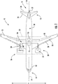
- FIG. 1 provides a top view of an exemplary aircraft 10 as may incorporate various embodiments of the present disclosure.
- the aircraft 10 defines a longitudinal centerline 14 that extends therethrough, a lateral direction L, a forward end 16, and an aft end 18.
- the aircraft 10 includes a fuselage 12, extending longitudinally from the forward end 16 of the aircraft 10 to the aft end 18 of the aircraft 10, and an empennage 19 at the aft end of the aircraft 10.
- the aircraft 10 includes a wing assembly including a first, port side wing 20 and a second, starboard side wing 22.
- the first and second wings 20, 22 each extend laterally outward with respect to the longitudinal centerline 14.
- the first wing 20 and a portion of the fuselage 12 together define a first side 24 of the aircraft 10, and the second wing 22 and another portion of the fuselage 12 together define a second side 26 of the aircraft 10.
- the first side 24 of the aircraft 10 is configured as the port side of the aircraft 10
- the second side 26 of the aircraft 10 is configured as the starboard side of the aircraft 10.
- Each of the wings 20, 22 for the exemplary embodiment depicted includes one or more leading edge flaps 28 and one or more trailing edge flaps 30.
- the aircraft 10 further includes, or rather, the empennage 19 of the aircraft 10 includes, a vertical stabilizer 32 having a rudder flap (not shown) for yaw control, and a pair of horizontal stabilizers 34, each having an elevator flap 36 for pitch control.
- the fuselage 12 additionally includes an outer surface or skin 38. It should be appreciated however, that in other exemplary embodiments of the present disclosure, the aircraft 10 may additionally or alternatively include any other suitable configuration. For example, in other embodiments, the aircraft 10 may include any other configuration of stabilizer.
- the exemplary aircraft 10 of FIG. 1 additionally includes a hybrid-electric propulsion system 50 having a first propulsor assembly 52 and a second propulsor assembly 54.
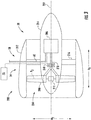
- FIG. 2 provides a schematic, cross-sectional view of the first propulsor assembly 52
- FIG. 3 provides a schematic, cross-sectional view of the second propulsor assembly 54.
- the first propulsor assembly 52 and second propulsor assembly 54 are each configured in an underwing-mounted configuration.
- one or both of the first and second propulsor assemblies 52, 54 may in other exemplary embodiments be mounted at any other suitable location.
- the exemplary hybrid-electric propulsion system 50 generally includes the first propulsor assembly 52 having a combustion engine and a prime propulsor (which, for the embodiment of FIG. 2 are configured together as a gas turbine engine, or rather as a turbofan engine 100), an electric machine 56 (which for the embodiment depicted in FIG. 2 is an electric motor/generator) drivingly coupled to the combustion engine, the second propulsor assembly 54 (which for the embodiment of FIG.
- the power bus 58 may include various switches or other power electronics movable to selectively electrically connect the various components of the hybrid electric propulsion system 50. Additionally, the power bus 58 may further include power electronics, such as inverters, converters, rectifiers, etc., for conditioning or converting electrical power within the hybrid electric propulsion system 50.
- the controller 72 may be configured to distribute electrical power between the various components of the hybrid-electric propulsion system 50.
- the controller 72 may be operable with the power bus 58 (including the one or more switches or other power electronics) to provide electrical power to, or draw electrical power from, the various components, such as the electric machine 56, to operate the hybrid electric propulsion system 50 between various operating modes.
- the electric lines 60 of the power bus 58 extending through the controller 72.
- the controller 72 may be a stand-alone controller, dedicated to the hybrid-electric propulsion system 50, or alternatively, may be incorporated into one or more of a main system controller for the aircraft 10, a separate controller for the exemplary turbofan engine 100 (such as a full authority digital engine control system for the turbofan engine 100, also referred to as a FADEC), etc.
- the electric energy storage unit 55 may be configured as one or more batteries, such as one or more lithium-ion batteries, or alternatively may be configured as any other suitable electrical energy storage devices. It will be appreciated that for the hybrid-electric propulsion system 50 described herein, the electric energy storage unit 55 is configured to store a relatively large amount of electrical power. For example, in certain exemplary embodiments, the electric energy storage unit may be configured to store at least about fifty kilowatt hours of electrical power, such as at least about sixty-five kilowatt hours of electrical power, such as at least about seventy-five kilowatts hours of electrical power, and up to about five hundred kilowatt hours of electrical power.
- the first propulsor assembly 52 includes a gas turbine engine mounted, or configured to be mounted, to the first wing 20 of the aircraft 10. More specifically, for the embodiment of FIG. 2 , the gas turbine engine includes a turbomachine 102 and a prime propulsor, the prime propulsor being a fan (referred to as "fan 104" with reference to FIG. 2 ). Accordingly, for the embodiment of FIG. 2 , the gas turbine engine is configured as a turbofan engine 100.
- the turbofan engine 100 defines an axial direction A1 (extending parallel to a longitudinal centerline 101 provided for reference) and a radial direction R1. As stated, the turbofan engine 100 includes the fan 104 and the turbomachine 102 disposed downstream from the fan 104.
- the exemplary turbomachine 102 depicted generally includes a substantially tubular outer casing 106 that defines an annular inlet 108.
- the outer casing 106 encases, in serial flow relationship, a compressor section including a booster or low pressure (LP) compressor 110 and a high pressure (HP) compressor 112; a combustion section 114; a turbine section including a first, high pressure (HP) turbine 116 and a second, low pressure (LP) turbine 118; and a jet exhaust nozzle section 120.
- the compressor section, combustion section 114, and turbine section together define at least in part a core air flowpath 121 through the turbomachine 102.
- the turbofan engine 100 includes a fuel delivery system 115 for providing fuel to the combustion section 114.
- the exemplary turbomachine 102 of the turbofan engine 100 additionally includes one or more shafts rotatable with at least a portion of the turbine section and, for the embodiment depicted, at least a portion of the compressor section. More particularly, for the embodiment depicted, the turbofan engine 100 includes a high pressure (HP) shaft or spool 122, which drivingly connects the HP turbine 116 to the HP compressor 112. Additionally, the exemplary turbofan engine 100 includes a low pressure (LP) shaft or spool 124, which drivingly connects the LP turbine 118 to the LP compressor 110.
- HP high pressure
- LP low pressure
- the exemplary fan 104 depicted is configured as a variable pitch fan having a plurality of fan blades 128 coupled to a disk 130 in a spaced apart manner.
- the fan blades 128 extend outwardly from disk 130 generally along the radial direction R1.
- Each fan blade 128 is rotatable relative to the disk 130 about a respective pitch axis P1 by virtue of the fan blades 128 being operatively coupled to a suitable actuation member 132 configured to collectively vary the pitch of the fan blades 128.
- the fan 104 is mechanically coupled to the LP shaft 124, such that the fan 104 is mechanically driven by the second, LP turbine 118.
- the fan 104 including the fan blades 128, disk 130, and actuation member 132, is mechanically coupled to the LP shaft 124 through a power gearbox 134, and is rotatable about the longitudinal axis 101 by the LP shaft 124 across the power gear box 134.
- the power gear box 134 includes a plurality of gears for stepping down the rotational speed of the LP shaft 124 to a more efficient rotational fan speed. Accordingly, the fan 104 is powered by an LP system (including the LP turbine 118) of the turbomachine 102.
- the disk 130 is covered by rotatable front hub 136 aerodynamically contoured to promote an airflow through the plurality of fan blades 128.
- the turbofan engine 100 includes an annular fan casing or outer nacelle 138 that circumferentially surrounds the fan 104 and/or at least a portion of the turbomachine 102. Accordingly, the exemplary turbofan engine 100 depicted may be referred to as a "ducted" turbofan engine.
- the nacelle 138 is supported relative to the turbomachine 102 by a plurality of circumferentially-spaced outlet guide vanes 140. A downstream section 142 of the nacelle 138 extends over an outer portion of the turbomachine 102 so as to define a bypass airflow passage 144 therebetween.
- the hybrid-electric propulsion system 50 additionally includes an electric machine 56, which for the embodiment depicted is configured as an electric motor/generator.
- the electric machine 56 is, for the embodiment depicted, positioned within the turbomachine 102 of the turbofan engine 100, inward of the core air flowpath 121, and is in mechanical communication with one of the shafts of the turbofan engine 100. More specifically, for the embodiment depicted, the electric machine is driven by the second, LP turbine 118 through the LP shaft 124.
- the electric machine 56 may be configured to convert mechanical power of the LP shaft 124 to electric power, or alternatively the electric machine 56 may be configured to convert electrical power provided thereto into mechanical power for the LP shaft 124.
- the electric machine 56 may instead be positioned at any other suitable location within the turbomachine 102 or elsewhere.
- the electric machine 56 may be, in other embodiments, mounted coaxially with the LP shaft 124 within the turbine section, or alternatively may be offset from the LP shaft 124 and driven through a suitable gear train.
- the electric machine 56 may instead be powered by the HP system, i.e., by the HP turbine 116 through, e.g., the HP shaft 122, or by both the LP system (e.g., the LP shaft 124) and the HP system (e.g., the HP shaft 122) via a dual drive system.
- the electric machine 56 may include a plurality of electric machines, e.g., with one being drivingly connected to the LP system (e.g., the LP shaft 124) and one being drivingly connected to the HP system (e.g., the HP shaft 122). Further, although the electric machine 56 is described as an electric motor/generator, in other exemplary embodiments, the electric machine 56 may be configured solely as an electric motor, or solely as an electric generator.
- the turbofan engine 100 further includes a controller 150 and a plurality of sensors.
- the plurality of sensors may be configured to sense data indicative of various operating parameters of the turbofan engine 100.
- the one or more sensors may be configured to determine a temperature within the gas turbine engine, a rotational speed of one or more components of the gas turbine engine, an amount of fuel provided to the combustion section 114 of the gas turbine engine, and/or an amount of thrust being generated by the gas turbine engine.
- the plurality of sensors include: a sensor 152 for sensing data indicative of a compressor exit temperature; a sensor 154 configured for sensing data indicative of an exhaust gas temperature; a sensor 156 configured for sensing data indicative of a turbine inlet temperature; a sensor 158 configured for sensing data indicative of a rotational speed of the LP shaft 124; a sensor 160 configured for sensing data indicative of a rotational speed of the HP shaft 122; a sensor 162 operable with the fuel delivery system 115 and configured for sensing data indicative of a fuel flow parameter to the combustion section 114; and a sensor 164 operable with one or both of the electric machine 56 and the power bus 58 for sensing data indicative of an amount of electrical power provided to, or extracted from, the electric machine 56.
- the sensor 164 may be positioned at any other suitable location, or configured in any suitable manner, for sensing data indicative of an amount of electrical power provided to, or extracted from, the electric machine 56.
- the controller 150 may be a full authority digital engine control system, also referred to as a FADEC.
- the controller 150 of the turbofan engine 100 may be configured to control operation of, e.g., the actuation member 132, the fuel delivery system 115 for the combustion section 114, etc.
- the controller 150 may be operably connected to the plurality of sensors 152, 154, 156, 158, 160, 162 and configured to receive data sensed by the respective sensors to determine various operational parameters of the turbofan engine 100.
- the controller 150 of the turbofan engine 100 is operably connected to the controller 72 of the hybrid-electric propulsion system 50.
- controller 72 may further be operably connected to one or more of the first propulsor assembly 52 (including controller 150), the electric machine 56, the second propulsor assembly 54, and the energy storage unit 55 through a suitable wired or wireless communication system (depicted in phantom).
- the exemplary turbofan engine 100 depicted in FIG. 2 may, in other exemplary embodiments, have any other suitable configuration.
- the fan 104 may not be a variable pitch fan, and further, in other exemplary embodiments, the LP shaft 124 may be directly mechanically coupled to the fan 104 (i.e., the turbofan engine 100 may not include the gearbox 134).
- the turbofan engine 100 may be configured as any other suitable gas turbine engine.
- the turbofan engine 100 may instead be configured as a turboprop engine, an unducted turbofan engine, a turbojet engine, a turboshaft engine, etc.
- the exemplary hybrid-electric propulsion system 50 additionally includes the second propulsor assembly 54 mounted, for the embodiment depicted, to the second wing 22 of the aircraft 10.
- the second propulsor assembly 54 is generally configured as an electric propulsor assembly 200 including an electric motor 206 and a propulsor/fan 204.
- the electric propulsor assembly 200 defines an axial direction A2 extending along a longitudinal centerline axis 202 that extends therethrough for reference, as well as a radial direction R2.
- the fan 204 is rotatable about the centerline axis 202 by the electric motor 206.
- the fan 204 includes a plurality of fan blades 208 and a fan shaft 210.
- the plurality of fan blades 208 are attached to/rotatable with the fan shaft 210 and spaced generally along a circumferential direction of the electric propulsor assembly 200 (not shown).
- the plurality of fan blades 208 may be attached in a fixed manner to the fan shaft 210, or alternatively, the plurality of fan blades 208 may be rotatable relative to the fan shaft 210, such as in the embodiment depicted.
- the plurality of fan blades 208 each define a respective pitch axis P2, and for the embodiment depicted are attached to the fan shaft 210 such that a pitch of each of the plurality of fan blades 208 may be changed, e.g., in unison, by a pitch change mechanism 211. Changing the pitch of the plurality of fan blades 208 may increase an efficiency of the second propulsor assembly 54 and/or may allow the second propulsor assembly 54 to achieve a desired thrust profile.
- the fan 204 may be referred to as a variable pitch fan.
- the electric propulsor assembly 200 depicted additionally includes a fan casing or outer nacelle 212, attached to a core 214 of the electric propulsor assembly 200 through one or more struts or outlet guide vanes 216.
- the outer nacelle 212 substantially completely surrounds the fan 204, and particularly the plurality of fan blades 208. Accordingly, for the embodiment depicted, the electric propulsor assembly 200 may be referred to as a ducted electric fan.
- the fan shaft 210 is mechanically coupled to the electric motor 206 within the core 214, such that the electric motor 206 drives the fan 204 through the fan shaft 210.
- the fan shaft 210 is supported by one or more bearings 218, such as one or more roller bearings, ball bearings, or any other suitable bearings.
- the electric motor 206 may be an inrunner electric motor (i.e., including a rotor positioned radially inward of a stator), or alternatively may be an outrunner electric motor (i.e., including a stator positioned radially inward of a rotor), or alternatively, still, may be an axial flux electric motor (i.e., with the rotor neither outside the stator nor inside the stator, but rather offset from it along the axis of the electric motor).
- the electric power source e.g., the electric machine 56 or the electric energy storage unit 55
- the electric propulsor assembly 200 i.e., the electric motor 206
- the electric motor 206 is in electrical communication with the electric machine 56 and/or the electric energy storage unit 55 through the electrical power bus 58, and more particularly through the one or more electrical cables or lines 60 extending therebetween.
- the exemplary hybrid-electric propulsion system 50 may have any other suitable configuration, and further, may be integrated into an aircraft 10 in any other suitable manner.
- the electric propulsor assembly 200 of the hybrid electric propulsion system 50 may instead be configured as a plurality of electric propulsor assemblies 200 and/or the hybrid electric propulsion system 50 may further include a plurality of gas turbine engines (such as turbofan engine 100) and electric machines 56.
- the electric propulsor assembly(ies) 200 and/or gas turbine engine(s) and electric machine(s) 56 may be mounted to the aircraft 10 at any other suitable location in any other suitable manner (including, e.g., tail mounted configurations).
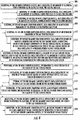
- a computer implemented method 300 of assessing a health of a gas turbine engine of a hybrid electric propulsion system for an aircraft is provided.
- the exemplary hybrid electric propulsion system may be configured in accordance with one or more of the exemplary embodiments described above with reference to FIGS. 1 through 3 . Accordingly, in certain exemplary aspects, the hybrid electric propulsion system may, in addition to the gas turbine engine, include an electric machine rotatable with the gas turbine engine.
- the exemplary method 300 generally includes at (302) receiving, by one or more computing devices, data indicative of an amount of electrical power provided to, or extracted from, the electric machine.
- receiving, by the one or more computing devices, the data at (302) may include at (304) receiving, by the one or more computing devices, data indicative of an amount of electrical power provided to the electric machine, or alternatively, may include at (306) receiving, by the one or more computing devices, data indicative of an amount of electrical power extracted from the electric machine.
- receiving, by the one or more computing devices, data indicative of the amount of electrical power provided to, or extracted from, the electric machine at (302) may further include determining the amount of electrical power provided to, or extracted from, the electric machine based at least in part on data received by the one or more sensors.
- the method 300 includes at (308) receiving, by the one or more computing devices, data indicative of an operating parameter of the hybrid electric propulsion system.
- receiving, by the one or more computing devices, data indicative of the operating parameter of the hybrid electric propulsion system at (308) includes at (310) receiving, by the one or more computing devices, data indicative of an operating parameter of the gas turbine engine. More specifically, for the exemplary aspect of FIG.
- receiving, by the one or more computing devices, data indicative of the operating parameter of the gas turbine engine at (310) includes at (312) receiving, by the one or more computing devices, data indicative of one or more of a temperature within the gas turbine engine, a rotational speed of one or more components of the gas turbine engine, an amount of fuel provided to a combustion section of the gas turbine engine, or data indicative of a pressure within the gas turbine engine (which may, in turn, be indicative of an amount of thrust being produced by the gas turbine engine).
- the temperature within the gas turbine engine may refer to, e.g., a compressor exit temperature, a turbine inlet temperature, or exhaust gas temperature.
- the rotational speed of one or more components of the gas turbine engine may include a rotational speed of a low pressure shaft or of a high pressure shaft.
- the pressure within the gas turbine may include a compressor exit pressure or a turbine exit pressure.
- the method 300 further includes at (314) assessing, by the one or more computing devices, a health of the gas turbine engine based at least in part on the received data indicative of the amount of electrical power provided to, or extracted from the electric machine at (302) and the received data indicative of the operating parameter of the hybrid electric propulsion system at (304).
- the amount of electrical power provided to, or extracted from, the electric machine during a given operating mode may indicate a health of the engine, such as a deterioration value of the engine.
- the "operating mode" may be, e.g., a power level of the gas turbine engine, which may be determined based on the received data indicative of the one or more operating parameters of the hybrid electric propulsion system, such as of the gas turbine engine. Additionally, or alternatively, the operating mode may be determined by an aircraft parameter such as on-ground, takeoff, climb, cruise, or descent parameters.
- a value of the one or more operating parameters of the hybrid electric propulsion system such as of the gas turbine engine, which may be determined based on the received data indicative of the parameter, for a given power level of the electric machine (i.e., for a given amount of power provided by the electric machine or extracted from the electric machine), may also indicate a health the engine, such as the deterioration value of the engine.
- the deterioration value may be a percent deterioration, or any other suitable value.
- the method 300 may determine an exhaust gas temperature value while extracting a reference amount of electrical power from the electric machine.
- the value of the exhaust gas temperature for the reference amount of electrical power being extracted from the electric machine may be indicative of the health of the engine. For example, when the engine is new, or healthy, the exhaust gas temperature may be at a first value when extracting the reference amount of electrical power from the electric machine. By contrast when the engine is old, or relatively unhealthy, the exhaust gas temperature may be at a second, higher value when extracting the reference amount of electrical power from the electric machine.
- the method 300 may determine an amount of electrical power being extracted from the electric machine while the gas turbine engine is operated to define a reference exhaust gas temperature.
- the amount of electrical power being extracted from the gas turbine engine may be indicative of the health of the engine. For example, when the engine is new, or healthy, the electrical power being extracted from the gas turbine engine may be a first value while the gas turbine engine is operated at the reference exhaust gas temperature. By contrast, when the engine is old, or relatively unhealthy, the electric power being extracted from the gas turbine engine may be a second, lower value while the gas turbine engine is operated at the reference exhaust gas temperature.
- assessing, by the one or more computing devices, the health of the gas turbine engine based at least in part on the received data indicative of the amount of electrical power provided to, or extracted from, the electric machine at (302) and the received data indicative of the operating parameter of the hybrid electric propulsion system at (304) may include comparing the received data indicative of the operating parameter of the hybrid electric propulsion system at (304) to a reference operating parameter value, a reference chart of operating parameter values, etc. to assess the engine health, and/or comparing the received data indicative of the amount of electrical power provided to, or extracted from the electric machine at (302) to a reference power level value, a reference chart of power level values, etc. to assess the engine health.
- any other suitable gas turbine engine parameter, or hybrid electric propulsion system parameter may be utilized.
- the exemplary aspect of the method 300 depicted includes at (316) providing, by one or more computing devices, information to a user indicative of the health of the gas turbine engine.
- providing, by the one or more computing devices, information to the user indicative of the health of the gas turbine engine at (316) includes at (318) displaying, by the one or more computing devices, data indicative of the health of the gas turbine engine on a user interface device, such as a screen or other display device, and at (319) storing, by the one or more computing devices, data indicative of the health of the gas turbine engine to one or more storage devices.
- the "user” may be a member of a flight crew of an aircraft including the exemplary propulsion system, or may be a user gathering data from, e.g., a fleet of aircraft, or alternatively may be any other suitable user.
- the method 300 depicted includes at (320) scheduling, by the one or more computing devices, a maintenance operation for the gas turbine engine response to assessing, by the one or more computing devices, the health of the gas turbine engine at (314).
- assessing, by the one or more computing devices, the health of the gas turbine engine at (314) may include determining, by the one or more computing devices, an engine deterioration value of the gas turbine engine is above the predetermined threshold, in which case, scheduling, by the one or more computing devices, the maintenance operation for the gas turbine engine at (320) may include scheduling, by the one or more computing devices, the maintenance operation for the gas turbine engine further in response to the determination that the engine deterioration value for the gas turbine engine being above the predetermined threshold.
- the method may modify operation of the hybrid electric propulsion system, including the gas turbine engine, in response to the assessed health of the gas turbine engine.
- the exemplary aspect of the method 300 depicted includes at (322) modifying, by the one or more computing devices, operation of the gas turbine engine in response to assessing, by the one or more computing devices, the health of the gas turbine engine at (314).
- modifying, by the one or more computing devices, operation of the gas turbine engine at (322) includes at (324) modifying, by the one or more computing devices, an engine parameter indicative of a stall margin of the gas turbine engine in response to the assessment, by the one or more computing devices, of the health of the gas turbine at (314).
- a stall margin of the gas turbine engine may generally need to be increased (or rather an engine parameter indicative of, i.e., tied to, the stall margin may generally need to be increased) to reduce a risk of compressor stall within a compressor section of the gas turbine engine.
- Such an exemplary aspect may allow for a reduced stall margin, or at least a more appropriate stall margin, for the engine to be utilized during operation, potentially increasing an efficiency of the engine.
- the method 300 may be configured to assess a health of a gas turbine engine in any other suitable manner.
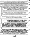
- the method 300 may be configured to "probe" the hybrid electric propulsion system to determine a health of a gas turbine engine of the electric propulsion system. More specifically, referring now to FIG. 5 , such an exemplary aspect of the method 300 is provided.
- the exemplary aspect of FIG. 5 may be substantially the same as the exemplary aspect of FIG. 4 .
- the exemplary aspect of the method 300 depicted in FIG. 5 generally includes at (302) receiving, by one or more computing devices, data indicative of an amount of electrical power provided to, or extracted from the electric machine; at (304) receiving, by the one or more computing devices, data indicative of an operating parameter of the hybrid electric propulsion system; and at (314) assessing, by the one or more computing devices, a health of the gas turbine engine based at least in part on the received data at (302) and the received data at (304).
- the exemplary aspect of the method 300 depicted in FIG. 5 additionally includes "probing" the hybrid electric propulsion system. More specifically, for the exemplary aspect of the method 300 depicted in FIG. 5 , the method 300 further includes at (326) changing, by the one or more computing devices, an amount of fuel provided to the combustion section of the gas turbine engine for an amount of time. In addition, for the exemplary aspect of the method 300 depicted in FIG.
- determining, by the one or more computing devices, the amount of electrical power provided to, or extracted from, the electric machine at (302) includes at (328) receiving, by the one or more computing devices, data indicative of a change in the amount of electrical power provided to, or extracted from, the electric machine during at least a portion of the amount of time, and further, at (330) determining, by the one or more computing devices, a change in the amount of electrical power provided to, or extracted from, the electric machine during at least a portion of the amount of time.
- the amount of time may be a relatively short amount of time, such as one minute or less, such as thirty seconds or less, such as fifteen seconds or less, or such as five seconds or less.
- changing, by the one or more computing devices, the amount of fuel provided to the combustion section of the gas turbine engine for the amount of time at (326) may include increasing the amount of fuel provided to the combustion section of the gas turbine engine for the amount of time.
- determining, by the one or more computing devices, the change in the amount of electrical power provided to, or extracted from, the electric machine at (330) may further include determining, by the one or more computing devices, an increase in the amount of electrical power extracted from the electric machine during at least a portion of the amount of time.
- changing, by the one or more computing devices, the amount of fuel provided to the combustion section of the gas turbine engine for the amount of time at (326) may include decreasing the amount of fuel provided to the combustion section of the gas turbine engine for the amount of time.
- determining, by the one or more computing devices, the change in the amount of electrical power provided to, or extracted from, the electric machine at (330) may further include determining, by the one or more computing devices, a decrease in the amount of electrical power extracted from the electric machine during at least a portion of the amount of time.
- receiving, by the one or more computing devices, data indicative of the operating parameter of the hybrid electric propulsion system at (304) may include at (331) receiving, by the one or more computing devices, data indicative of a change in a fuel flow parameter during the amount time.
- the fuel flow parameter may be a fuel flowrate, or the total amount of fuel provided during a certain amount of time.
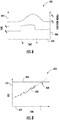
- a chart 400 depicting the exemplary aspect of the method 300 depicted in FIG. 5 is provided.
- the chart 400 generally depicts a fuel flow parameter (on a first Y-axis 402) over of time (on an X-axis 404) and a power extracted from the electric machine (on a second Y-axis 406) over time (the power on the second Y-axis 406 being inferred from one or more power indicators/ engine parameters). More particularly, the chart 400 of FIG. 6 depicts these parameters over the amount of time in which the fuel provided to the combustion section of the gas turbine engine is changed at (326). The amount of time is the time between t 0 and t 1 in the chart 400.
- the fuel flowrate parameter is increased from R 0 to R 1 at to, and then decreased from R 1 to R 0 at t 1 .
- the amount of power extracted from the electric machine increases. More specifically, between t 0 and t 1 the amount of power extracted from the electric machine increases from P 0 to P 1 .
- assessing, by the one or more computing devices, the health of the gas turbine engine at (314) further includes at (332) assessing, by the one or more computing devices, the health of the gas turbine engine based at least in part on the received data indicative of the change in the amount of fuel provided to the combustion section of the gas turbine engine at (331) and the received data indicative of the change in the amount of electrical power provided to, or extracted from, the electric machine during at least a portion of the amount of time at (328).
- assessing, by the one or more computing devices, the health of the gas turbine engine at (332) may include comparing the received data indicative of the change in the amount of electrical power provided to, or extracted from, the electric machine at (328), for a given change in the amount of fuel provided to the combustion section the gas turbine engine determined based on the received data at (331), to a baseline number (e.g., a baseline amount of electrical power) to determine the health of the gas turbine engine, or alternatively to a schedule to determine the health of the gas turbine engine.
- a baseline number e.g., a baseline amount of electrical power
- this information may be used in any other suitable manner to assess a health of the engine.
- the exemplary method 300 may be operable in still other suitable manners.
- the exemplary method 300 may be operable in a predictive manner to anticipate, e.g., necessary maintenance operations. Accordingly, referring now also to FIG. 7 , another exemplary aspect of the method 300 is depicted.
- the exemplary method 300 of FIG. 7 may be similar to the exemplary method 300 of FIG. 4 .
- the exemplary aspect of the method 300 depicted in FIG. 7 generally includes at (302) receiving, by one or more computing devices, data indicative of an amount of electrical power provided to, or extracted from the electric machine; at (304) receiving, by the one or more computing devices, data indicative of an operating parameter of the hybrid electric propulsion system; and at (314) assessing, by the one or more computing devices, a health of the gas turbine engine based at least in part on the received data at (302) and the received data at (304).
- the exemplary aspect of the method 300 depicted in FIG. 7 is further operable in a predictive manner to, e.g., anticipate necessary maintenance operations. More specifically, for the exemplary aspect of the method 300 depicted in FIG. 7 , receiving, by the one or more computing devices, data indicative of the amount of electrical power provided to, or extracted from, the electric machine at (302) includes at (334) receiving, by the one or more computing devices, data indicative of the amount of electrical power provided to, or extracted from, the electric machine over a plurality of operation cycles.
- the plurality of operation cycles may be a plurality of operation cycles of the gas turbine engine, the hybrid electric propulsion system as a whole, and/or of an aircraft incorporating the hybrid electric propulsion system.
- receiving, by the one or more computing devices, data indicative of the operating parameter of the hybrid electric propulsion system at (304) includes at (336) receiving, by the one or more computing devices, data indicative of the operating parameter of the hybrid electric propulsion system over the plurality of operation cycles.
- assessing, by the one or more computing devices, the health of the gas turbine engine at (314) further includes at (338) comparing, by the one or more computing devices, the received data indicative of the amount of electrical power provided to, or extracted from the electric machine over the plurality of operation cycles at (334) and the received data indicative of the operating parameters of the hybrid electric propulsion system over the plurality of operation cycles at (336). More specifically, for the exemplary aspect of the method 300 depicted in FIG. 7 , assessing, by the one or more computing devices, the health of the gas turbine engine at (314) further includes at (340) trending, by the one or more computing devices, the compared information at (338) over a time variable or a cycle variable.
- trending at (340), by the one or more computing devices, the compared information may include plotting a value of the operating parameter for a given amount of electrical power provided to, or extracted from, the electric machine; or in the alternative, plotting, a value of the amount of electrical power provided to, or extracted from, the electric machine for a given value of the operating parameter.
- trending at (340), by the one or more computing devices, the compared information may further include assigning or determining a line of best fit for the plotted data points using, e.g., least mean squares, or any other suitable method.
- assessing, by the one or more computing devices, the health of the gas turbine engine at (314) further includes at (342) determining, by the one or more computing devices, one or both of an amount of time or number of cycles until a maintenance operation for the gas turbine engine is needed based on the trending of the compared information over the time variable or the cycle variable at (340).
- determining, by the one or more computing devices, the amount of time until the maintenance operation for the gas turbine engine is needed at (342) may include extrapolating or extending out the line of best fit determined for the plotted data, and determining when such extrapolated or extended out line of best fit intersects with a threshold for requiring the maintenance operation for the gas turbine engine.
- the exemplary aspect of the method 300 depicted in FIG. 7 may predict when a maintenance operation for the gas turbine engine will be needed.
- the method 300 further includes at (320) scheduling, by the one or more computing devices, the maintenance operation for the gas turbine engine in response to assessing, by the one or more computing devices, the health of the gas turbine engine (314), or more specifically, at (344) scheduling, by one or more computing devices, the maintenance operation for the gas turbine engine in response to determining, by the one or more computing devices, the amount of time until the maintenance operation for the gas turbine engine is needed at (342).
- the chart 450 generally depicts an operating parameter of the hybrid electric propulsion system (on a Y-axis 452) over of time (on an X-axis 454). More particularly, for the exemplary embodiment of FIG. 8 , the chart 450 depicts an exhaust gas temperature as the operating parameter of the hybrid electric propulsion system on the Y-axis 452 over time on the X-axis 454. More particularly, the values of exhaust gas temperature charted are for a particular amount of electrical power provided to, or extracted from, the electric machine. Accordingly, for each of the values of the exhaust gas temperature charted, a constant amount of electrical power was being provided to, or extracted from the electric machine.
- the chart 450 further includes a line of best fit 456 for the various exhaust gas temperature values charted.
- the line of best fit 456 may be determined using a least mean squared method, or any other suitable method.
- a line 458 is depicted in phantom in the chart 450 representing an exhaust gas temperature limit for the particular amount of electrical power being provided to, or extracted from, the electric machine.
- an anticipated point 460 at which the exhaust gas temperature values will reach the exhaust gas temperature limit represented by line 458 may be determined.
- the chart 450 (or similar methodology) may be used to predict a point at which a gas turbine engine will need to undergo a maintenance operation (e.g., the time, t, corresponding to point 460).
- the operating parameter the hybrid electric propulsion system may be any other suitable operating parameter, and further, instead of time being used on the X-axis 454, the chart 450 may use engine cycles.
- the computing system 500 can be used, for example, as a controller 72 in a hybrid electric propulsion system 50.
- the computing system 500 can include one or more computing device(s) 510.
- the computing device(s) 510 can include one or more processor(s) 510A and one or more memory device(s) 510B.
- the one or more processor(s) 510A can include any suitable processing device, such as a microprocessor, microcontroller, integrated circuit, logic device, and/or other suitable processing device.
- the one or more memory device(s) 510B can include one or more computer-readable media, including, but not limited to, non-transitory computer-readable media, RAM, ROM, hard drives, flash drives, and/or other memory devices.
- the one or more memory device(s) 510B can store information accessible by the one or more processor(s) 510A, including computer-readable instructions 510C that can be executed by the one or more processor(s) 510A.
- the instructions 510C can be any set of instructions that when executed by the one or more processor(s) 510A, cause the one or more processor(s) 510A to perform operations.
- the instructions 510C can be executed by the one or more processor(s) 510A to cause the one or more processor(s) 510A to perform operations, such as any of the operations and functions for which the computing system 500 and/or the computing device(s) 510 are configured, the operations for assessing a health of a gas turbine engine of a hybrid electric propulsion system for an aircraft (e.g, method 300), as described herein, and/or any other operations or functions of the one or more computing device(s) 510.
- the exemplary computing system 500 may be configured as an engine health assessment control system.
- the instructions 510C can be software written in any suitable programming language or can be implemented in hardware. Additionally, and/or alternatively, the instructions 510C can be executed in logically and/or virtually separate threads on processor(s) 510A.
- the memory device(s) 510B can further store data 510D that can be accessed by the processor(s) 510A.
- the data 510D can include data indicative of operational parameters of the aircraft and/or the hybrid electric propulsion system, data indicative of performance maps for the aircraft and/or the hybrid electric propulsion system, any user input, such as flight phase data, and/or any other data and/or information described herein.
- the computing device(s) 510 can also include a network interface 510E used to communicate, for example, with the other components of system 500 (e.g., via a network).
- the network interface 510E can include any suitable components for interfacing with one or more network(s), including for example, transmitters, receivers, ports, controllers, antennas, and/or other suitable components.
- One or more external display devices can be configured to receive one or more commands from the computing device(s) 510.
Landscapes
- Engineering & Computer Science (AREA)
- Mechanical Engineering (AREA)
- Aviation & Aerospace Engineering (AREA)
- Chemical & Material Sciences (AREA)
- Combustion & Propulsion (AREA)
- Physics & Mathematics (AREA)
- General Physics & Mathematics (AREA)
- General Engineering & Computer Science (AREA)
- Engine Equipment That Uses Special Cycles (AREA)
- Control Of Turbines (AREA)
- Control Of Eletrric Generators (AREA)
Applications Claiming Priority (1)
| Application Number | Priority Date | Filing Date | Title |
|---|---|---|---|
| US15/621,279 US10762726B2 (en) | 2017-06-13 | 2017-06-13 | Hybrid-electric propulsion system for an aircraft |
Publications (2)
| Publication Number | Publication Date |
|---|---|
| EP3415438A1 true EP3415438A1 (fr) | 2018-12-19 |
| EP3415438B1 EP3415438B1 (fr) | 2021-08-04 |
Family
ID=62750764
Family Applications (1)
| Application Number | Title | Priority Date | Filing Date |
|---|---|---|---|
| EP18177534.7A Active EP3415438B1 (fr) | 2017-06-13 | 2018-06-13 | Système de propulsion hybride-électrique pour un aéronef |
Country Status (5)
| Country | Link |
|---|---|
| US (1) | US10762726B2 (fr) |
| EP (1) | EP3415438B1 (fr) |
| JP (1) | JP6727664B2 (fr) |
| CN (1) | CN109083747B (fr) |
| CA (1) | CA3006682C (fr) |
Cited By (1)
| Publication number | Priority date | Publication date | Assignee | Title |
|---|---|---|---|---|
| US10762726B2 (en) | 2017-06-13 | 2020-09-01 | General Electric Company | Hybrid-electric propulsion system for an aircraft |
Families Citing this family (49)
| Publication number | Priority date | Publication date | Assignee | Title |
|---|---|---|---|---|
| US10962448B2 (en) * | 2016-06-17 | 2021-03-30 | Airbus Operations Sas | Method for monitoring the engines of an aircraft |
| US10442547B2 (en) * | 2017-06-22 | 2019-10-15 | General Electric Company | Engine and electrical machine health monitoring |
| US20190002117A1 (en) * | 2017-06-30 | 2019-01-03 | General Electric Company | Propulsion system for an aircraft |
| CN109229361A (zh) * | 2017-07-11 | 2019-01-18 | 深圳市道通智能航空技术有限公司 | 电机控制系统及无人机 |
| US10968765B2 (en) * | 2018-12-04 | 2021-04-06 | General Electric Company | Power system with a coordinated power draw |
| US11162382B2 (en) * | 2019-02-21 | 2021-11-02 | General Electric Company | Method and system for engine operation |
| CN119099858A (zh) * | 2019-08-28 | 2024-12-10 | 株式会社电装 | 电动航空器及电动航空器的控制装置 |
| JP7276002B2 (ja) * | 2019-08-28 | 2023-05-18 | 株式会社デンソー | 電動垂直離着陸機および電動垂直離着陸機の制御装置 |
| JP7276253B2 (ja) * | 2019-08-28 | 2023-05-18 | 株式会社デンソー | 電動垂直離着陸機および電動垂直離着陸機の制御装置 |
| US11618580B2 (en) * | 2020-08-31 | 2023-04-04 | General Electric Company | Hybrid electric aircraft engine |
| MX2023003968A (es) * | 2020-10-05 | 2023-04-24 | Alakai Tech Corporation | Sistema y metodo de evaluacion y monitoreo de salud para vehiculos electricos de combustible limpio. |
| US20230138476A1 (en) * | 2021-10-29 | 2023-05-04 | Raytheon Technologies Corporation | Hybrid electric single engine descent restart |
| US12202616B2 (en) | 2021-11-04 | 2025-01-21 | General Electric Company | Relight of a propulsion system with a fuel cell |
| US11794912B2 (en) | 2022-01-04 | 2023-10-24 | General Electric Company | Systems and methods for reducing emissions with a fuel cell |
| US12037952B2 (en) | 2022-01-04 | 2024-07-16 | General Electric Company | Systems and methods for providing output products to a combustion chamber of a gas turbine engine |
| US12123361B2 (en) | 2022-01-04 | 2024-10-22 | General Electric Company | Systems and methods for providing output products to a combustion chamber of a gas turbine engine |
| US11719441B2 (en) | 2022-01-04 | 2023-08-08 | General Electric Company | Systems and methods for providing output products to a combustion chamber of a gas turbine engine |
| US11933216B2 (en) | 2022-01-04 | 2024-03-19 | General Electric Company | Systems and methods for providing output products to a combustion chamber of a gas turbine engine |
| US11970282B2 (en) | 2022-01-05 | 2024-04-30 | General Electric Company | Aircraft thrust management with a fuel cell |
| US12034298B2 (en) | 2022-01-10 | 2024-07-09 | General Electric Company | Power source for an aircraft |
| US11804607B2 (en) | 2022-01-21 | 2023-10-31 | General Electric Company | Cooling of a fuel cell assembly |
| US12074350B2 (en) | 2022-01-21 | 2024-08-27 | General Electric Company | Solid oxide fuel cell assembly |
| US12573647B2 (en) | 2022-01-21 | 2026-03-10 | General Electric Company | Solid oxide fuel cell assembly |
| US12351329B2 (en) | 2022-01-21 | 2025-07-08 | General Electric Company | Systems and method of operating a fuel cell assembly |
| US12037124B2 (en) | 2022-01-21 | 2024-07-16 | General Electric Company | Systems and method of operating a fuel cell assembly |
| US12129789B2 (en) | 2022-02-21 | 2024-10-29 | General Electric Company | Systems and method of operating a fuel cell assembly, a gas turbine engine, or both |
| US11967743B2 (en) | 2022-02-21 | 2024-04-23 | General Electric Company | Modular fuel cell assembly |
| US12170390B2 (en) | 2022-02-21 | 2024-12-17 | General Electric Company | Systems and method of operating a fuel cell assembly, a gas turbine engine, or both |
| FR3133642A1 (fr) * | 2022-03-15 | 2023-09-22 | Safran Aircraft Engines | Procédé et unité de commande d’ensemble moteur |
| US12025061B2 (en) | 2022-04-04 | 2024-07-02 | General Electric Company | Gas turbine engine with fuel cell assembly |
| US12195192B2 (en) * | 2022-04-30 | 2025-01-14 | Beta Air Llc | Hybrid propulsion systems for an electric aircraft |
| US11634232B1 (en) * | 2022-04-30 | 2023-04-25 | Beta Air, Llc | Hybrid propulsion systems for an electric aircraft |
| US11639230B1 (en) * | 2022-04-30 | 2023-05-02 | Beta Air, Llc | System for an integral hybrid electric aircraft |
| US12428164B2 (en) | 2022-05-16 | 2025-09-30 | General Electric Company | Environmental control system having a fuel cell assembly |
| US12412914B2 (en) | 2022-05-16 | 2025-09-09 | General Electric Company | Environmental control system having a fuel cell assembly |
| US12043406B2 (en) | 2022-05-27 | 2024-07-23 | General Electric Company | Method of operating a fuel cell assembly for an aircraft |
| US11817700B1 (en) | 2022-07-20 | 2023-11-14 | General Electric Company | Decentralized electrical power allocation system |
| CN115355105B (zh) * | 2022-08-17 | 2024-10-25 | 北京航空航天大学杭州创新研究院 | 用于分析可持续航空燃料高空排放的民航缩比涡扇发动机 |
| US12301002B2 (en) | 2022-08-26 | 2025-05-13 | General Electric Company | Power dispatch control system for multiple power generation sources |
| US12071904B2 (en) * | 2022-10-19 | 2024-08-27 | Mitsubishi Power Aero LLC | Systems and methods for bleed valve testing in gas turbine engines |
| US12567595B2 (en) | 2022-11-10 | 2026-03-03 | General Electric Company | Gas turbine combustion section having an integrated fuel cell assembly |
| US12240613B2 (en) | 2022-11-10 | 2025-03-04 | General Electric Company | Gas turbine combustion section having an integrated fuel cell assembly |
| US11923586B1 (en) | 2022-11-10 | 2024-03-05 | General Electric Company | Gas turbine combustion section having an integrated fuel cell assembly |
| US11859820B1 (en) | 2022-11-10 | 2024-01-02 | General Electric Company | Gas turbine combustion section having an integrated fuel cell assembly |
| US12078350B2 (en) | 2022-11-10 | 2024-09-03 | General Electric Company | Gas turbine combustion section having an integrated fuel cell assembly |
| FR3145553B1 (fr) * | 2023-02-08 | 2025-01-10 | Airbus Helicopters | Procédé de test d’une installation motrice hybride équipant un aéronef, programme d’ordinateur et aéronef associés |
| CN118532263A (zh) | 2023-02-23 | 2024-08-23 | 通用电气公司 | 燃气涡轮发动机和燃料电池组件 |
| CN118532265A (zh) | 2023-02-23 | 2024-08-23 | 通用电气公司 | 燃气涡轮发动机和燃料电池组件 |
| CN118532266A (zh) | 2023-02-23 | 2024-08-23 | 通用电气公司 | 燃气涡轮发动机和燃料电池组件 |
Citations (6)
| Publication number | Priority date | Publication date | Assignee | Title |
|---|---|---|---|---|
| US20140271114A1 (en) * | 2013-03-13 | 2014-09-18 | Rolls-Royce North America Technologies, Inc. | Engine Health Monitoring and Power Allocation Control for a Turbine Engine Using Electric Generators |
| US20150100181A1 (en) * | 2013-10-04 | 2015-04-09 | Sikorsky Aircraft Corporation | Electrified Rotorcraft |
| EP2966266A1 (fr) * | 2014-07-09 | 2016-01-13 | Rolls-Royce plc | Moteur à turbine à gaz en deux parties |
| US20160096634A1 (en) * | 2014-10-06 | 2016-04-07 | Snecma | Monitoring of an aircraft propulsion system |
| EP3093235A1 (fr) * | 2015-05-13 | 2016-11-16 | Rolls-Royce plc | Avion |
| EP3095695A1 (fr) * | 2015-05-15 | 2016-11-23 | Airbus Helicopters | Procede pour activer un moteur electrique d'une installation hybride d'un aeronef multimoteur, et un aeronef |
Family Cites Families (153)
| Publication number | Priority date | Publication date | Assignee | Title |
|---|---|---|---|---|
| US987641A (en) | 1910-06-20 | 1911-03-21 | Jeremiah A Moynihan | Car-replacer. |
| US2812912A (en) | 1953-08-06 | 1957-11-12 | Northrop Aircraft Inc | Inclined engine installation for jet aircraft |
| US3194516A (en) | 1962-10-22 | 1965-07-13 | Messerschmitt Ag | Arrangement for jet engines at the tail end of aircraft |
| GB1024894A (en) | 1963-05-16 | 1966-04-06 | Vickers Armstrongs Aircraft | Improvements in aircraft jet-propulsion power-plants |
| US3286470A (en) | 1963-11-14 | 1966-11-22 | Gen Electric | Tip-turbine fan with thrust reverser |
| US3312448A (en) | 1965-03-01 | 1967-04-04 | Gen Electric | Seal arrangement for preventing leakage of lubricant in gas turbine engines |
| US3844110A (en) | 1973-02-26 | 1974-10-29 | Gen Electric | Gas turbine engine internal lubricant sump venting and pressurization system |
| US4089493A (en) | 1976-09-29 | 1978-05-16 | Paulson Allen E | Aircraft with combination power plant |
| US4370560A (en) | 1979-10-15 | 1983-01-25 | Sundstrand Corporation | Compressor load control for an auxiliary power unit |
| US4605185A (en) | 1983-10-17 | 1986-08-12 | Daniel Reyes | Airplane powered by vehicular motor |
| US4913380A (en) | 1988-10-13 | 1990-04-03 | Omac, Inc. | Fuel system for Canard aircraft |
| US5174109A (en) | 1990-10-25 | 1992-12-29 | Sundstrand Corporation | Clutch to disconnect loads during turbine start-up |
| US6105697A (en) | 1996-04-01 | 2000-08-22 | Weaver; Winstead B. | Hybrid turbine-electric motor system |
| US5799484A (en) | 1997-04-15 | 1998-09-01 | Allied Signal Inc | Dual turbogenerator auxiliary power system |
| US5927644A (en) | 1997-10-08 | 1999-07-27 | General Electric Company | Double failsafe engine mount |
| CA2318944C (fr) | 1997-12-20 | 2007-09-11 | Alliedsignal Inc. | Controleur pour maintenir la temperature entree turbine constante d'un systeme de generation d'energie de microturbine |
| US6992403B1 (en) | 2001-03-08 | 2006-01-31 | Pacific Scientific | Electric power and start system |
| US6545373B1 (en) | 2001-08-24 | 2003-04-08 | Smiths Aerospace, Inc. | System and method for providing ballast loading for a turbo-generator |
| GB2394991B (en) | 2002-11-06 | 2006-02-15 | Rolls Royce Plc | Mounting arrangement |
| US6834831B2 (en) | 2002-12-31 | 2004-12-28 | The Boeing Company | Hybrid solid oxide fuel cell aircraft auxiliary power unit |
| US8631657B2 (en) | 2003-01-22 | 2014-01-21 | Vast Power Portfolio, Llc | Thermodynamic cycles with thermal diluent |
| GB2400411B (en) | 2003-04-10 | 2006-09-06 | Rolls Royce Plc | Turbofan arrangement |
| US7387189B2 (en) | 2003-08-14 | 2008-06-17 | United Technologies Corp. | Emergency lubrication system |
| US7417337B1 (en) | 2003-09-04 | 2008-08-26 | Hamilton Sundstrand Corporation | Method and system for facilitating no-break power transfer |
| US7975465B2 (en) | 2003-10-27 | 2011-07-12 | United Technologies Corporation | Hybrid engine accessory power system |
| US6996968B2 (en) | 2003-12-17 | 2006-02-14 | United Technologies Corporation | Bifurcated oil scavenge system for a gas turbine engine |
| DE10359559A1 (de) | 2003-12-18 | 2005-07-28 | Mtu Aero Engines Gmbh | Gasturbine, insbesondere Flugtriebwerk |
| US7251942B2 (en) | 2004-06-29 | 2007-08-07 | Honeywell International Inc. | Integrated gearless and nonlubricated auxiliary power unit |
| FR2873096B1 (fr) | 2004-07-15 | 2007-11-23 | Airbus France Sas | Avion multimoteur |
| GB0418454D0 (en) | 2004-08-19 | 2004-09-22 | Rolls Royce Plc | An engine mounting assembly |
| US7285871B2 (en) | 2004-08-25 | 2007-10-23 | Honeywell International, Inc. | Engine power extraction control system |
| WO2006059978A1 (fr) | 2004-12-01 | 2006-06-08 | United Technologies Corporation | Moteur a turbine de bout en porte-a-faux |
| US7976273B2 (en) | 2004-12-01 | 2011-07-12 | United Technologies Corporation | Tip turbine engine support structure |
| US7267300B2 (en) | 2005-02-25 | 2007-09-11 | The Boeing Company | Aircraft capable of vertical and short take-off and landing |
| US7380749B2 (en) | 2005-04-21 | 2008-06-03 | The Boeing Company | Combined fuel cell aircraft auxiliary power unit and environmental control system |
| US7677502B2 (en) | 2005-09-29 | 2010-03-16 | The Boeing Company | Method and apparatus for generating lift |
| US8141360B1 (en) | 2005-10-18 | 2012-03-27 | Florida Turbine Technologies, Inc. | Hybrid gas turbine and internal combustion engine |
| US7493754B2 (en) | 2005-10-19 | 2009-02-24 | General Electric Company | Gas turbine engine assembly and methods of assembling same |
| US7958727B2 (en) | 2005-12-29 | 2011-06-14 | Honeywell International Inc. | Electric boost compressor and turbine generator system |
| FR2899200B1 (fr) | 2006-03-28 | 2008-11-07 | Airbus France Sas | Aeronef a impact environnemental reduit |
| FR2902759B1 (fr) | 2006-06-27 | 2008-10-24 | Turbomeca | Systeme de generation de puissance pour aeronef utilisant une pile a combustible |
| FR2903666B1 (fr) | 2006-07-11 | 2008-10-10 | Airbus France Sas | Ensemble moteur pour aeronef comprenant un capotage aerodynamique de jonction monte sur deux elements distincts |
| US7717672B2 (en) | 2006-08-29 | 2010-05-18 | Honeywell International Inc. | Radial vaned diffusion system with integral service routings |
| US7752834B2 (en) | 2006-10-25 | 2010-07-13 | United Technologies Corporation | Aircraft propulsion systems |
| US7665689B2 (en) | 2006-11-24 | 2010-02-23 | The Boeing Company | Unconventional integrated propulsion systems and methods for blended wing body aircraft |
| DE102006056354B4 (de) | 2006-11-29 | 2013-04-11 | Airbus Operations Gmbh | Hybridantrieb für ein Flugzeug |
| US7514810B2 (en) | 2006-12-15 | 2009-04-07 | General Electric Company | Electric power generation using power turbine aft of LPT |
| DE102007055336A1 (de) | 2007-01-15 | 2008-08-21 | GIF Gesellschaft für Industrieforschung mbH | Flugzeugpropellerantrieb, Verfahren zum Antreiben eines Flugzeugpropellers und Verwendung eines Lagers eines Flugzeugpropellerantriebs sowie Verwendung einer Elektromaschine |
| US7970497B2 (en) | 2007-03-02 | 2011-06-28 | Honeywell International Inc. | Smart hybrid electric and bleed architecture |
| FR2921978B1 (fr) | 2007-10-08 | 2014-04-11 | Snecma | Turboreacteur a generateur electrique agence dans la soufflante |
| US8193761B1 (en) | 2007-11-08 | 2012-06-05 | Honeywell International, Inc. | Hybrid power source |
| US8727271B2 (en) | 2008-01-11 | 2014-05-20 | Ival O. Salyer | Aircraft using turbo-electric hybrid propulsion system |
| WO2009091834A1 (fr) | 2008-01-14 | 2009-07-23 | Internal Combustion Turbines Llc | Turbogénérateur entraîné par un moteur à combustion interne pour véhicules hybrides et génération de puissance |
| FR2928137B1 (fr) | 2008-02-29 | 2010-08-20 | Airbus France | Systeme de propulsion arriere d'avion fixe par poutres et avion comportant un tel systeme. |
| CZ300681B6 (cs) | 2008-08-20 | 2009-07-15 | Vycítal@Jirí | Hybridní pohon letadla |
| US8226040B2 (en) | 2008-08-25 | 2012-07-24 | Embraer S.A. | Continuous fuel management system for automatic control of aircraft center of gravity |
| DE102008048915B4 (de) | 2008-09-26 | 2017-05-18 | Airbus Operations Gmbh | Leistungsverteilungssystem |
| US8099944B2 (en) | 2008-10-08 | 2012-01-24 | The Invention Science Fund I, Llc | Hybrid propulsive engine including at least one independently rotatable propeller/fan |
| US20100126178A1 (en) * | 2008-10-08 | 2010-05-27 | Searete Llc, A Limited Liability Corporation Of The State Of Delaware | Hybrid propulsive engine including at least one independently rotatable turbine stator |
| US20100108806A1 (en) | 2008-10-08 | 2010-05-06 | Searete Llc, A Limited Liability Corporation Of The State Of Delaware | Hybrid propulsive engine including at least one independently rotatable propeller/fan |
| US8039983B2 (en) | 2008-12-02 | 2011-10-18 | The Boeing Company | Systems and methods for providing AC power from multiple turbine engine spools |
| US8128019B2 (en) | 2008-12-12 | 2012-03-06 | Honeywell International Inc. | Hybrid power for ducted fan unmanned aerial systems |
| US8469306B2 (en) | 2009-01-27 | 2013-06-25 | Ira F. Kuhn, Jr. | Purebred and hybrid electric VTOL tilt rotor aircraft |
| FR2945268B1 (fr) | 2009-05-05 | 2013-05-17 | Airbus France | Generateur electrique sur une partie tournante de turbopropulseur |
| US8167062B2 (en) | 2009-05-21 | 2012-05-01 | Tognum America Inc. | Power generation system and method for assembling the same |
| GB0909158D0 (en) | 2009-05-29 | 2009-07-08 | Rolls Royce Plc | An aircraft having a lift/propulsion unit |
| US20110016882A1 (en) | 2009-07-24 | 2011-01-27 | Sarah Ann Woelke | Electrical Cable Shroud |
| US8568938B2 (en) | 2009-08-28 | 2013-10-29 | The Boeing Company | Thermoelectric generator and fuel cell for electric power co-generation |
| US8657227B1 (en) | 2009-09-11 | 2014-02-25 | The Boeing Company | Independent power generation in aircraft |
| FR2952907B1 (fr) | 2009-11-26 | 2011-12-09 | Eurocopter France | Installation motrice, helicoptere comportant une telle installation motrice, et procede mis en oeuvre par cette installation motrice |
| US7818969B1 (en) | 2009-12-18 | 2010-10-26 | Energyield, Llc | Enhanced efficiency turbine |
| US8489246B2 (en) | 2010-02-26 | 2013-07-16 | Pratt & Whitney Canada Corp. | Hybrid control system |
| FR2958689B1 (fr) | 2010-04-12 | 2012-04-20 | Aircelle Sa | Systeme de commande d'un dispositif electrique d'une nacelle |
| DE102010014637B4 (de) | 2010-04-12 | 2016-05-04 | MTU Aero Engines AG | Verfahren zum Konservieren eines Kraftstoffsystems und eines Ölsystems |
| US9143023B1 (en) | 2010-05-17 | 2015-09-22 | Richard Christopher Uskert | Electromagnetic propulsive motor |
| DE102010021022A1 (de) | 2010-05-19 | 2011-11-24 | Eads Deutschland Gmbh | Kippflügel-Flugzeug |
| JP2012008782A (ja) * | 2010-06-24 | 2012-01-12 | Mitsubishi Heavy Ind Ltd | プラントの機能を診断する方法、及びプラント監視装置 |
| US8522522B2 (en) | 2010-07-30 | 2013-09-03 | Hamilton Sundstrand Corporation | Fan embedded power generator |
| US9702254B2 (en) | 2010-09-14 | 2017-07-11 | Manuel M. Saiz | Lift propulsion and stabilizing system and procedure for vertical take-off and landing aircraft |
| US8836160B1 (en) | 2010-09-28 | 2014-09-16 | The Boeing Company | Method and application for vehicle power system isolation |
| US8684304B2 (en) | 2010-11-16 | 2014-04-01 | Rolls-Royce Corporation | Aircraft, propulsion system, and system for taxiing an aircraft |
| US8727270B2 (en) | 2010-11-16 | 2014-05-20 | Rolls-Royce Corporation | Aircraft, propulsion system, and system for taxiing an aircraft |
| US9212625B2 (en) | 2010-11-19 | 2015-12-15 | Rudolph Allen SHELLEY | Hybrid gas turbine propulsion system |
| JP5611064B2 (ja) | 2011-01-19 | 2014-10-22 | 三菱重工業株式会社 | 劣化診断装置、発電システム、及び劣化診断方法 |
| US20120209456A1 (en) | 2011-02-15 | 2012-08-16 | Government Of The United States, As Represented By The Secretary Of The Air Force | Parallel Hybrid-Electric Propulsion Systems for Unmanned Aircraft |
| US20120214605A1 (en) | 2011-02-21 | 2012-08-23 | General Electric Company | Gas Turbine Engine Generator System with Torsional Damping Coupling |
| US8432048B1 (en) | 2011-03-08 | 2013-04-30 | Florida Turbine Technologies, Inc. | Hybrid engine with a gas turbine engine |
| GB201104733D0 (en) | 2011-03-21 | 2011-05-04 | Lee Christopher J | Charging unit for hybrid electrically powered aircraft |
| US8552575B2 (en) | 2011-04-03 | 2013-10-08 | Tma Power, Llc | Hybrid electric power for vehicular propulsion |
| FR2975547B1 (fr) | 2011-05-20 | 2013-06-07 | Turbomeca | Procede de rationalisation de chaine de composants electriques d'un aeronef, architecture de mise en oeuvre et aeronef correspondant |
| US9540998B2 (en) | 2011-05-27 | 2017-01-10 | Daniel K. Schlak | Integral gas turbine, flywheel, generator, and method for hybrid operation thereof |
| FR2977030B1 (fr) | 2011-06-22 | 2013-07-12 | Airbus Operations Sas | Procede d'equilibrage pour systeme propulsif a helices contrarotatives coaxiales non carenees |
| FR2978124B1 (fr) | 2011-07-18 | 2013-08-02 | Eurocopter France | Procede de controle d'un groupe de moteurs et aeronef |
| FR2978728B1 (fr) | 2011-08-03 | 2014-07-04 | Eads Europ Aeronautic Defence | Architecture de propulsion d'aeronef integrant un systeme de recuperation d'energie |
| US8500064B2 (en) | 2011-08-10 | 2013-08-06 | Hamilton Sundstrand Corporation | Hybrid power system architecture for an aircraft |
| US9828105B2 (en) | 2011-08-24 | 2017-11-28 | United Technologies Corporation | Nacelle assembly having integrated afterbody mount case |
| US8928166B2 (en) | 2011-08-31 | 2015-01-06 | Hamilton Sundstrand Corporation | Mixed mode power generation architecture |
| US20130062885A1 (en) | 2011-09-08 | 2013-03-14 | General Electric Company | Method and apparatus for extracting electrical power from a gas turbine engine |
| US10036335B2 (en) * | 2011-09-15 | 2018-07-31 | General Electric Company | Systems and methods for diagnosing an engine |
| GB201117104D0 (en) | 2011-10-05 | 2011-11-16 | Rolls Royce Plc | A duct |
| US8723349B2 (en) | 2011-10-07 | 2014-05-13 | General Electric Company | Apparatus for generating power from a turbine engine |
| US8723385B2 (en) | 2011-10-07 | 2014-05-13 | General Electric Company | Generator |
| GB201117692D0 (en) | 2011-10-13 | 2011-11-23 | Rolls Royce Plc | A distributed propulsion system and method of control |
| US9004849B2 (en) | 2012-01-10 | 2015-04-14 | United Technologies Corporation | Gas turbine engine forward bearing compartment architecture |
| US9038398B2 (en) | 2012-02-27 | 2015-05-26 | United Technologies Corporation | Gas turbine engine buffer cooling system |
| US9102326B2 (en) | 2012-03-05 | 2015-08-11 | Embry-Riddle Aeronautical University, Inc. | Hybrid assembly for an aircraft |
| US9340299B2 (en) | 2012-03-30 | 2016-05-17 | W. Morrison Consulting Group, Inc. | Long range electric aircraft and method of operating same |
| GB201207754D0 (en) | 2012-05-03 | 2012-06-13 | Rolls Royce Plc | Electro-magnetic coupling system |
| US9296288B2 (en) | 2012-05-07 | 2016-03-29 | Separation Design Group Llc | Hybrid radiant energy aircraft engine |
| FR2990414B1 (fr) | 2012-05-10 | 2015-04-10 | Microturbo | Procede de fourniture de puissance auxiliaire par un groupe auxiliaire de puissance et architecture correspondante |
| DE102012209803A1 (de) | 2012-06-12 | 2013-12-12 | Siemens Aktiengesellschaft | Verfahren zum Bereitstellen einer vorbestimmten Antriebscharakteristik in einem Flugzeug und zugehörige Antriebsvorrichtung |
| DE102012209807A1 (de) | 2012-06-12 | 2013-12-12 | Siemens Aktiengesellschaft | Flugzeug und Verfahren zum Herstellen eines Flugzeugs |
| CA2820254C (fr) | 2012-07-09 | 2020-02-18 | Mcmaster University | Systeme de groupe propulseur hybride |
| FR2993727B1 (fr) | 2012-07-19 | 2017-07-21 | Eurocopter France | Machine electrique reversible pour aeronef |
| US8939399B2 (en) | 2012-07-31 | 2015-01-27 | Textron Innovations Inc. | System and method of augmenting power in a rotorcraft |
| US9540944B2 (en) * | 2012-09-28 | 2017-01-10 | United Technologies Corporation | Real time model based compressor control |
| US9068562B1 (en) | 2012-10-05 | 2015-06-30 | The Boeing Company | Laser-powered propulsion system |
| US8957539B1 (en) | 2012-10-16 | 2015-02-17 | The Boeing Company | Hybrid turbogenerator and associated method |
| GB201219916D0 (en) | 2012-11-06 | 2012-12-19 | Rolls Royce Plc | An electrical generation arrangement for an aircraft |
| FR2997681B1 (fr) | 2012-11-08 | 2015-05-15 | Snecma | Avion propulse par un turboreacteur a soufflantes contrarotatives |
| US9045996B2 (en) | 2012-11-20 | 2015-06-02 | Honeywell International Inc. | Gas turbine engine optimization by electric power transfer |
| US9255525B2 (en) * | 2012-11-30 | 2016-02-09 | General Electric Company | System and method for gas turbine operation |
| WO2014123740A1 (fr) | 2013-02-06 | 2014-08-14 | United Technologies Corporation | Module de régulation d'huile |
| US8742605B1 (en) | 2013-02-07 | 2014-06-03 | Hamilton Sundstrand Corporation | Method for aircraft engine start using synchronous generator and constant speed drive |
| US8997493B2 (en) | 2013-02-20 | 2015-04-07 | Hamilton Sunstrand Corporation | Auxiliary power unit generator |
| EP2964530B1 (fr) | 2013-03-09 | 2019-10-30 | Rolls-Royce Corporation | Groupe motopropulseur d'avion |
| CA2905233C (fr) | 2013-03-14 | 2022-04-26 | Rolls-Royce Corporation | Systeme de commande intelligent integre et procede |
| FR3003514B1 (fr) | 2013-03-25 | 2016-11-18 | Eurocopter France | Aeronef a voilure tournante a motorisation hybride. |
| US9318991B2 (en) | 2013-04-11 | 2016-04-19 | The Boeing Company | Electric motor frequency modulation system |
| US9193451B2 (en) | 2013-04-22 | 2015-11-24 | Ival O. Salyer | Aircraft using turbo-electric hybrid propulsion system for multi-mode operation |
| ITFI20130130A1 (it) | 2013-05-31 | 2014-12-01 | Nuovo Pignone Srl | "gas turbines in mechanical drive applications and operating methods" |
| FR3006997B1 (fr) | 2013-06-14 | 2016-12-23 | Airbus | Aeronef a moyens de propulsion electriques |
| US10144524B2 (en) | 2013-06-14 | 2018-12-04 | Rohr, Inc. | Assembly for mounting a turbine engine to a pylon |
| FR3011144B1 (fr) | 2013-09-26 | 2018-06-15 | Dassault Aviation | Procede et module de protection contre les pics de couple entre moteur et une machine electrique |
| US9130494B2 (en) | 2013-09-26 | 2015-09-08 | The Boeing Company | Electric motor phase control system |
| US9428263B2 (en) | 2013-10-16 | 2016-08-30 | The Boeing Company | Frequency response and health tracker for a synthetic jet generator |
| US10113487B2 (en) | 2013-10-24 | 2018-10-30 | United Technologies Corporation | Cascaded multi-variable control system for a turboshaft engine |
| US11267574B2 (en) | 2013-10-28 | 2022-03-08 | The Boeing Company | Aircraft with electric motor and rechargeable power source |
| GB201320988D0 (en) | 2013-11-28 | 2014-01-15 | Rolls Royce Plc | An aircraft |
| US9815564B2 (en) | 2013-12-04 | 2017-11-14 | The Boeing Company | Non-propulsive utility power (NPUP) generation system for providing full-time secondary power during operation of an aircraft |
| US9366182B2 (en) | 2013-12-06 | 2016-06-14 | Rolls-Royce Corporation | Integrated electrical power and thermal management system |
| US9771163B2 (en) | 2013-12-31 | 2017-09-26 | The Boeing Company | Short takeoff and landing aircraft |
| GB2526611B (en) | 2014-05-30 | 2017-09-20 | William Lefley Paul | Hybrid Electric Ramjet Engine |
| US9643729B2 (en) * | 2014-06-20 | 2017-05-09 | Electronair Llc | Energy cell regenerative system for electrically powered aircraft |
| US10381889B2 (en) | 2014-06-27 | 2019-08-13 | General Electric Company | Permanent magnet machine with segmented sleeve for magnets |
| US9828109B2 (en) | 2014-07-23 | 2017-11-28 | Pratt & Whitney Canada Corp. | Apparatus and methods for powering an electrical device associated with an aircraft rotor |
| US10196923B2 (en) | 2014-08-28 | 2019-02-05 | Pratt & Whitney Canada Corp. | Operation of aircraft engines during transient conditions |
| CA2996844A1 (fr) * | 2014-08-29 | 2016-06-16 | Tzunum, Inc. | Chaine dynamique pour aeronef hybride electrique |
| US10112722B2 (en) | 2015-01-15 | 2018-10-30 | Unison Industries Llc | Power control for propeller-driven aircraft |
| GB201506473D0 (en) | 2015-04-16 | 2015-06-03 | Rolls Royce Plc | Aircraft propulsion system |
| US9909940B2 (en) | 2015-04-27 | 2018-03-06 | General Electric Company | System and method for non-invasive generator damping torque estimation |
| JP6730842B2 (ja) | 2015-05-05 | 2020-07-29 | ロールス−ロイス コーポレイション | 航空機の推進およびリフトのための電気直結駆動装置 |
| US10762726B2 (en) | 2017-06-13 | 2020-09-01 | General Electric Company | Hybrid-electric propulsion system for an aircraft |
-
2017
- 2017-06-13 US US15/621,279 patent/US10762726B2/en active Active
-
2018
- 2018-05-30 CA CA3006682A patent/CA3006682C/fr active Active
- 2018-06-08 JP JP2018109921A patent/JP6727664B2/ja active Active
- 2018-06-13 CN CN201810607616.3A patent/CN109083747B/zh active Active
- 2018-06-13 EP EP18177534.7A patent/EP3415438B1/fr active Active
Patent Citations (6)
| Publication number | Priority date | Publication date | Assignee | Title |
|---|---|---|---|---|
| US20140271114A1 (en) * | 2013-03-13 | 2014-09-18 | Rolls-Royce North America Technologies, Inc. | Engine Health Monitoring and Power Allocation Control for a Turbine Engine Using Electric Generators |
| US20150100181A1 (en) * | 2013-10-04 | 2015-04-09 | Sikorsky Aircraft Corporation | Electrified Rotorcraft |
| EP2966266A1 (fr) * | 2014-07-09 | 2016-01-13 | Rolls-Royce plc | Moteur à turbine à gaz en deux parties |
| US20160096634A1 (en) * | 2014-10-06 | 2016-04-07 | Snecma | Monitoring of an aircraft propulsion system |
| EP3093235A1 (fr) * | 2015-05-13 | 2016-11-16 | Rolls-Royce plc | Avion |
| EP3095695A1 (fr) * | 2015-05-15 | 2016-11-23 | Airbus Helicopters | Procede pour activer un moteur electrique d'une installation hybride d'un aeronef multimoteur, et un aeronef |
Cited By (1)
| Publication number | Priority date | Publication date | Assignee | Title |
|---|---|---|---|---|
| US10762726B2 (en) | 2017-06-13 | 2020-09-01 | General Electric Company | Hybrid-electric propulsion system for an aircraft |
Also Published As
| Publication number | Publication date |
|---|---|
| CN109083747A (zh) | 2018-12-25 |
| CN109083747B (zh) | 2021-07-23 |
| JP6727664B2 (ja) | 2020-07-22 |
| CA3006682C (fr) | 2021-02-16 |
| JP2019023069A (ja) | 2019-02-14 |
| US20180357840A1 (en) | 2018-12-13 |
| CA3006682A1 (fr) | 2018-12-13 |
| US10762726B2 (en) | 2020-09-01 |
| EP3415438B1 (fr) | 2021-08-04 |
Similar Documents
| Publication | Publication Date | Title |
|---|---|---|
| EP3415438B1 (fr) | Système de propulsion hybride-électrique pour un aéronef | |
| CA3009027C (fr) | Systeme de propulsion destine a un aeronef | |
| EP3421367B1 (fr) | Système de propulsion pour aéronef | |
| CN109229395B (zh) | 用于飞行器的推进系统及用于操作其的方法 | |
| EP3421369B1 (fr) | Système de propulsion pour aéronef | |
| CA3009004C (fr) | Systeme de propulsion destine a un aeronef | |
| CA3008406C (fr) | Systeme de propulsion destine a un aeronef | |
| US12540560B2 (en) | Propulsion system for an aircraft | |
| EP3421760A1 (fr) | Système de propulsion pour aéronef | |
| EP3418196B1 (fr) | Système de propulsion pour aéronef |
Legal Events
| Date | Code | Title | Description |
|---|---|---|---|
| PUAI | Public reference made under article 153(3) epc to a published international application that has entered the european phase |
Free format text: ORIGINAL CODE: 0009012 |
|
| STAA | Information on the status of an ep patent application or granted ep patent |
Free format text: STATUS: THE APPLICATION HAS BEEN PUBLISHED |
|
| AK | Designated contracting states |
Kind code of ref document: A1 Designated state(s): AL AT BE BG CH CY CZ DE DK EE ES FI FR GB GR HR HU IE IS IT LI LT LU LV MC MK MT NL NO PL PT RO RS SE SI SK SM TR |
|
| AX | Request for extension of the european patent |
Extension state: BA ME |
|
| STAA | Information on the status of an ep patent application or granted ep patent |
Free format text: STATUS: REQUEST FOR EXAMINATION WAS MADE |
|
| 17P | Request for examination filed |
Effective date: 20190619 |
|
| RBV | Designated contracting states (corrected) |
Designated state(s): AL AT BE BG CH CY CZ DE DK EE ES FI FR GB GR HR HU IE IS IT LI LT LU LV MC MK MT NL NO PL PT RO RS SE SI SK SM TR |
|
| STAA | Information on the status of an ep patent application or granted ep patent |
Free format text: STATUS: EXAMINATION IS IN PROGRESS |
|
| 17Q | First examination report despatched |
Effective date: 20200414 |
|
| GRAP | Despatch of communication of intention to grant a patent |
Free format text: ORIGINAL CODE: EPIDOSNIGR1 |
|
| STAA | Information on the status of an ep patent application or granted ep patent |
Free format text: STATUS: GRANT OF PATENT IS INTENDED |
|
| RIC1 | Information provided on ipc code assigned before grant |
Ipc: B64D 27/24 20060101AFI20210202BHEP Ipc: B64D 45/00 20060101ALN20210202BHEP Ipc: B64D 27/02 20060101ALN20210202BHEP |
|
| INTG | Intention to grant announced |
Effective date: 20210223 |
|
| GRAS | Grant fee paid |
Free format text: ORIGINAL CODE: EPIDOSNIGR3 |
|
| GRAA | (expected) grant |
Free format text: ORIGINAL CODE: 0009210 |
|
| STAA | Information on the status of an ep patent application or granted ep patent |
Free format text: STATUS: THE PATENT HAS BEEN GRANTED |
|
| AK | Designated contracting states |
Kind code of ref document: B1 Designated state(s): AL AT BE BG CH CY CZ DE DK EE ES FI FR GB GR HR HU IE IS IT LI LT LU LV MC MK MT NL NO PL PT RO RS SE SI SK SM TR |
|
| REG | Reference to a national code |
Ref country code: GB Ref legal event code: FG4D |
|
| REG | Reference to a national code |
Ref country code: AT Ref legal event code: REF Ref document number: 1416751 Country of ref document: AT Kind code of ref document: T Effective date: 20210815 |
|
| REG | Reference to a national code |
Ref country code: CH Ref legal event code: EP |
|
| REG | Reference to a national code |
Ref country code: DE Ref legal event code: R096 Ref document number: 602018021067 Country of ref document: DE |
|
| REG | Reference to a national code |
Ref country code: IE Ref legal event code: FG4D |
|
| REG | Reference to a national code |
Ref country code: LT Ref legal event code: MG9D |
|
| REG | Reference to a national code |
Ref country code: NL Ref legal event code: MP Effective date: 20210804 |
|
| REG | Reference to a national code |
Ref country code: AT Ref legal event code: MK05 Ref document number: 1416751 Country of ref document: AT Kind code of ref document: T Effective date: 20210804 |
|
| PG25 | Lapsed in a contracting state [announced via postgrant information from national office to epo] |
Ref country code: HR Free format text: LAPSE BECAUSE OF FAILURE TO SUBMIT A TRANSLATION OF THE DESCRIPTION OR TO PAY THE FEE WITHIN THE PRESCRIBED TIME-LIMIT Effective date: 20210804 Ref country code: ES Free format text: LAPSE BECAUSE OF FAILURE TO SUBMIT A TRANSLATION OF THE DESCRIPTION OR TO PAY THE FEE WITHIN THE PRESCRIBED TIME-LIMIT Effective date: 20210804 Ref country code: FI Free format text: LAPSE BECAUSE OF FAILURE TO SUBMIT A TRANSLATION OF THE DESCRIPTION OR TO PAY THE FEE WITHIN THE PRESCRIBED TIME-LIMIT Effective date: 20210804 Ref country code: RS Free format text: LAPSE BECAUSE OF FAILURE TO SUBMIT A TRANSLATION OF THE DESCRIPTION OR TO PAY THE FEE WITHIN THE PRESCRIBED TIME-LIMIT Effective date: 20210804 Ref country code: SE Free format text: LAPSE BECAUSE OF FAILURE TO SUBMIT A TRANSLATION OF THE DESCRIPTION OR TO PAY THE FEE WITHIN THE PRESCRIBED TIME-LIMIT Effective date: 20210804 Ref country code: AT Free format text: LAPSE BECAUSE OF FAILURE TO SUBMIT A TRANSLATION OF THE DESCRIPTION OR TO PAY THE FEE WITHIN THE PRESCRIBED TIME-LIMIT Effective date: 20210804 Ref country code: BG Free format text: LAPSE BECAUSE OF FAILURE TO SUBMIT A TRANSLATION OF THE DESCRIPTION OR TO PAY THE FEE WITHIN THE PRESCRIBED TIME-LIMIT Effective date: 20211104 Ref country code: LT Free format text: LAPSE BECAUSE OF FAILURE TO SUBMIT A TRANSLATION OF THE DESCRIPTION OR TO PAY THE FEE WITHIN THE PRESCRIBED TIME-LIMIT Effective date: 20210804 Ref country code: NO Free format text: LAPSE BECAUSE OF FAILURE TO SUBMIT A TRANSLATION OF THE DESCRIPTION OR TO PAY THE FEE WITHIN THE PRESCRIBED TIME-LIMIT Effective date: 20211104 Ref country code: PT Free format text: LAPSE BECAUSE OF FAILURE TO SUBMIT A TRANSLATION OF THE DESCRIPTION OR TO PAY THE FEE WITHIN THE PRESCRIBED TIME-LIMIT Effective date: 20211206 |
|
| PG25 | Lapsed in a contracting state [announced via postgrant information from national office to epo] |
Ref country code: PL Free format text: LAPSE BECAUSE OF FAILURE TO SUBMIT A TRANSLATION OF THE DESCRIPTION OR TO PAY THE FEE WITHIN THE PRESCRIBED TIME-LIMIT Effective date: 20210804 Ref country code: LV Free format text: LAPSE BECAUSE OF FAILURE TO SUBMIT A TRANSLATION OF THE DESCRIPTION OR TO PAY THE FEE WITHIN THE PRESCRIBED TIME-LIMIT Effective date: 20210804 Ref country code: GR Free format text: LAPSE BECAUSE OF FAILURE TO SUBMIT A TRANSLATION OF THE DESCRIPTION OR TO PAY THE FEE WITHIN THE PRESCRIBED TIME-LIMIT Effective date: 20211105 |
|
| PG25 | Lapsed in a contracting state [announced via postgrant information from national office to epo] |
Ref country code: NL Free format text: LAPSE BECAUSE OF FAILURE TO SUBMIT A TRANSLATION OF THE DESCRIPTION OR TO PAY THE FEE WITHIN THE PRESCRIBED TIME-LIMIT Effective date: 20210804 |
|
| PG25 | Lapsed in a contracting state [announced via postgrant information from national office to epo] |
Ref country code: DK Free format text: LAPSE BECAUSE OF FAILURE TO SUBMIT A TRANSLATION OF THE DESCRIPTION OR TO PAY THE FEE WITHIN THE PRESCRIBED TIME-LIMIT Effective date: 20210804 |
|
| REG | Reference to a national code |
Ref country code: DE Ref legal event code: R097 Ref document number: 602018021067 Country of ref document: DE |
|
| PG25 | Lapsed in a contracting state [announced via postgrant information from national office to epo] |
Ref country code: SM Free format text: LAPSE BECAUSE OF FAILURE TO SUBMIT A TRANSLATION OF THE DESCRIPTION OR TO PAY THE FEE WITHIN THE PRESCRIBED TIME-LIMIT Effective date: 20210804 Ref country code: SK Free format text: LAPSE BECAUSE OF FAILURE TO SUBMIT A TRANSLATION OF THE DESCRIPTION OR TO PAY THE FEE WITHIN THE PRESCRIBED TIME-LIMIT Effective date: 20210804 Ref country code: RO Free format text: LAPSE BECAUSE OF FAILURE TO SUBMIT A TRANSLATION OF THE DESCRIPTION OR TO PAY THE FEE WITHIN THE PRESCRIBED TIME-LIMIT Effective date: 20210804 Ref country code: EE Free format text: LAPSE BECAUSE OF FAILURE TO SUBMIT A TRANSLATION OF THE DESCRIPTION OR TO PAY THE FEE WITHIN THE PRESCRIBED TIME-LIMIT Effective date: 20210804 Ref country code: CZ Free format text: LAPSE BECAUSE OF FAILURE TO SUBMIT A TRANSLATION OF THE DESCRIPTION OR TO PAY THE FEE WITHIN THE PRESCRIBED TIME-LIMIT Effective date: 20210804 Ref country code: AL Free format text: LAPSE BECAUSE OF FAILURE TO SUBMIT A TRANSLATION OF THE DESCRIPTION OR TO PAY THE FEE WITHIN THE PRESCRIBED TIME-LIMIT Effective date: 20210804 |
|
| PLBE | No opposition filed within time limit |
Free format text: ORIGINAL CODE: 0009261 |
|
| STAA | Information on the status of an ep patent application or granted ep patent |
Free format text: STATUS: NO OPPOSITION FILED WITHIN TIME LIMIT |
|
| 26N | No opposition filed |
Effective date: 20220506 |
|
| PG25 | Lapsed in a contracting state [announced via postgrant information from national office to epo] |
Ref country code: IT Free format text: LAPSE BECAUSE OF FAILURE TO SUBMIT A TRANSLATION OF THE DESCRIPTION OR TO PAY THE FEE WITHIN THE PRESCRIBED TIME-LIMIT Effective date: 20210804 |
|
| PG25 | Lapsed in a contracting state [announced via postgrant information from national office to epo] |
Ref country code: SI Free format text: LAPSE BECAUSE OF FAILURE TO SUBMIT A TRANSLATION OF THE DESCRIPTION OR TO PAY THE FEE WITHIN THE PRESCRIBED TIME-LIMIT Effective date: 20210804 |
|
| PG25 | Lapsed in a contracting state [announced via postgrant information from national office to epo] |
Ref country code: MC Free format text: LAPSE BECAUSE OF FAILURE TO SUBMIT A TRANSLATION OF THE DESCRIPTION OR TO PAY THE FEE WITHIN THE PRESCRIBED TIME-LIMIT Effective date: 20210804 |
|
| REG | Reference to a national code |
Ref country code: CH Ref legal event code: PL |
|
| REG | Reference to a national code |
Ref country code: BE Ref legal event code: MM Effective date: 20220630 |
|
| PG25 | Lapsed in a contracting state [announced via postgrant information from national office to epo] |
Ref country code: LU Free format text: LAPSE BECAUSE OF NON-PAYMENT OF DUE FEES Effective date: 20220613 Ref country code: LI Free format text: LAPSE BECAUSE OF NON-PAYMENT OF DUE FEES Effective date: 20220630 Ref country code: IE Free format text: LAPSE BECAUSE OF NON-PAYMENT OF DUE FEES Effective date: 20220613 Ref country code: CH Free format text: LAPSE BECAUSE OF NON-PAYMENT OF DUE FEES Effective date: 20220630 |
|
| PG25 | Lapsed in a contracting state [announced via postgrant information from national office to epo] |
Ref country code: BE Free format text: LAPSE BECAUSE OF NON-PAYMENT OF DUE FEES Effective date: 20220630 |
|
| P01 | Opt-out of the competence of the unified patent court (upc) registered |
Effective date: 20230414 |
|
| PG25 | Lapsed in a contracting state [announced via postgrant information from national office to epo] |
Ref country code: HU Free format text: LAPSE BECAUSE OF FAILURE TO SUBMIT A TRANSLATION OF THE DESCRIPTION OR TO PAY THE FEE WITHIN THE PRESCRIBED TIME-LIMIT; INVALID AB INITIO Effective date: 20180613 |
|
| PG25 | Lapsed in a contracting state [announced via postgrant information from national office to epo] |
Ref country code: MK Free format text: LAPSE BECAUSE OF FAILURE TO SUBMIT A TRANSLATION OF THE DESCRIPTION OR TO PAY THE FEE WITHIN THE PRESCRIBED TIME-LIMIT Effective date: 20210804 Ref country code: CY Free format text: LAPSE BECAUSE OF FAILURE TO SUBMIT A TRANSLATION OF THE DESCRIPTION OR TO PAY THE FEE WITHIN THE PRESCRIBED TIME-LIMIT Effective date: 20210804 |
|
| PG25 | Lapsed in a contracting state [announced via postgrant information from national office to epo] |
Ref country code: TR Free format text: LAPSE BECAUSE OF FAILURE TO SUBMIT A TRANSLATION OF THE DESCRIPTION OR TO PAY THE FEE WITHIN THE PRESCRIBED TIME-LIMIT Effective date: 20210804 |
|
| PG25 | Lapsed in a contracting state [announced via postgrant information from national office to epo] |
Ref country code: MT Free format text: LAPSE BECAUSE OF FAILURE TO SUBMIT A TRANSLATION OF THE DESCRIPTION OR TO PAY THE FEE WITHIN THE PRESCRIBED TIME-LIMIT Effective date: 20210804 |
|
| PGFP | Annual fee paid to national office [announced via postgrant information from national office to epo] |
Ref country code: DE Payment date: 20250520 Year of fee payment: 8 |
|
| PGFP | Annual fee paid to national office [announced via postgrant information from national office to epo] |
Ref country code: GB Payment date: 20250520 Year of fee payment: 8 |
|
| PGFP | Annual fee paid to national office [announced via postgrant information from national office to epo] |
Ref country code: FR Payment date: 20250520 Year of fee payment: 8 |