EP3415676A2 - Calendre - Google Patents
Calendre Download PDFInfo
- Publication number
- EP3415676A2 EP3415676A2 EP18181952.5A EP18181952A EP3415676A2 EP 3415676 A2 EP3415676 A2 EP 3415676A2 EP 18181952 A EP18181952 A EP 18181952A EP 3415676 A2 EP3415676 A2 EP 3415676A2
- Authority
- EP
- European Patent Office
- Prior art keywords
- roller
- pivot
- nip
- calender
- frame
- Prior art date
- Legal status (The legal status is an assumption and is not a legal conclusion. Google has not performed a legal analysis and makes no representation as to the accuracy of the status listed.)
- Granted
Links
Images






Classifications
-
- D—TEXTILES; PAPER
- D06—TREATMENT OF TEXTILES OR THE LIKE; LAUNDERING; FLEXIBLE MATERIALS NOT OTHERWISE PROVIDED FOR
- D06C—FINISHING, DRESSING, TENTERING OR STRETCHING TEXTILE FABRICS
- D06C15/00—Calendering, pressing, ironing, glossing or glazing textile fabrics
- D06C15/02—Calendering, pressing, ironing, glossing or glazing textile fabrics between co-operating press or calender rolls
-
- D—TEXTILES; PAPER
- D21—PAPER-MAKING; PRODUCTION OF CELLULOSE
- D21G—CALENDERS; ACCESSORIES FOR PAPER-MAKING MACHINES
- D21G1/00—Calenders; Smoothing apparatus
-
- D—TEXTILES; PAPER
- D21—PAPER-MAKING; PRODUCTION OF CELLULOSE
- D21G—CALENDERS; ACCESSORIES FOR PAPER-MAKING MACHINES
- D21G1/00—Calenders; Smoothing apparatus
- D21G1/002—Opening or closing mechanisms; Regulating the pressure
-
- D—TEXTILES; PAPER
- D21—PAPER-MAKING; PRODUCTION OF CELLULOSE
- D21G—CALENDERS; ACCESSORIES FOR PAPER-MAKING MACHINES
- D21G1/00—Calenders; Smoothing apparatus
- D21G1/0073—Accessories for calenders
- D21G1/0086—Web feeding or guiding devices
Definitions
- the invention relates to a calender, with a frame in which a plurality of upper rollers and at least one lower roller are mounted.
- Replacing a roller is often expensive, especially for simple calenders. Numerous manual work is necessary. Mention should be the drive, the bearing lubrication, possibly the heater and of course the support of the roller. If the roller is heated, the roller to be replaced must first be time-consuming cooled and the new roller to be heated before starting production. Long downtimes and production downtimes are the result. For the fast roll change provided calender types are often expensive or require an enlarged roll diameter. In some variants, only one alternative roller is available for one or both of a nip roll. Some quick-change calenders are not suitable for certain types of applications, such as calendering fleece.
- the invention has set itself the task of creating a calender in which at least one roller of a nip can be exchanged quickly and which is improved in terms of at least one of the disadvantages mentioned.
- the calender according to the invention has a frame in which a plurality of top rollers and at least one bottom roller are mounted.
- the at least one lower roller can form a nip with a top roller.
- an inlet-side nip and an outlet-side nip can be provided by the calender.
- an inlet side and an outlet side nip can be provided by the calender at the same time.
- only one inlet-side or one outlet-side nip can be provided by the calender at a time.
- At least one lower roller is preferably provided with its own feed device, with which it can preferably be moved toward and away from an upper roller, particularly preferably translationally.
- the delivery device may comprise a hydraulic cylinder.
- delivery device and “delivery device” are synonymous in the context of this document.
- the calender serves to thermally strengthen nonwoven fabrics. It can act as a smooth roller against an engraved roller. Also, both rolls of a nips can be engraved. At least one of the two rolls of a nip can be heated. In order to produce different products, preferably the engraved roll is quickly exchangeable. In one embodiment, only the top roll of a nip is engraved.
- the calender is used for calendering paper or textile.
- a roller with a coating acts against a heated smooth or even engraved roller.
- cover are in the context of this Reference document on the one hand meant in particular rollers which have a resilient coating and on the other hand, in particular, in a wide use of this term, also cotton rollers.
- a quick exchange of the engraving may be desired. More often, however, there is a need to replace the pad to bring a different type or coating hardness used or regrind this, since wear takes place mainly on the softer pad.
- a rapid temperature change of the roll surface of at least one roll of a nip can be brought about by the roll change. This is preferably done without exceeding a temperature change in a roll of 1 to 10 K / min, since otherwise thermoelectric stresses in the roll material are to be feared.
- the calender allows a quick replacement of a roller, without manual intervention.
- a roller exchange in a shorter time than the heating or heating of the roller is possible.
- At least one lower roller is provided, which can be brought into two different working positions and more preferably forms a nip with different upper rollers.
- at least two different lower roller positions are preferably provided, of which only one is preferably selected at a time.
- Exactly one lower roller can therefore preferably; in one embodiment only sequentially; form two different nips whose position preferably differs from each other.
- the lower roller is provided tiltable and / or displaceable, preferably to serve the upstream side upper roller or the outlet side upper roller or two upper rollers simultaneously.
- outlet side is in the context of this document in particular the side of the calender designates, at which the goods enters the calender.
- outlet side is in the context of this document in particular the side of the calender designation, at which the goods leave the calender.
- a lower roller of the calender is arranged on a pair of rocker arms.
- the two rocker arms of this rocker arm pair are preferably only tiltable in pairs.
- This rocker arm pair preferably has two different end positions, in which, in each case, a contact surface of the pair of rocker arms more preferably bears against a counter-bearing surface of the frame.
- the tilting axis of the rocker arm pair is preferably located between the press plane of the inlet-side nip and the press plane of the outlet-side nip.
- the two end positions which occupies the lower roller in the two end positions of the Kipphebelpases, the two working positions of the lower roller, in which this preferably forms a nip with the associated upper roller.
- the calender comprises exactly one lower roller.
- the calender comprises more than one lower roll.
- more than one additional roll of a nip is kept ready for replacement.
- the calender comprises exactly two lower rolls, which are more preferably deliverable independently of one another.
- the feed movement of the lower rollers is preferably translational, preferably exclusively.
- At least one lower roller of the calender - with the exception of the feed movement - not displaced.
- the temperature or the surface quality of the lower roller can be changed quickly.
- the frame can be viewed from the side formed at least approximately "U" -shaped.
- the clear width of the "U" -shaped frame or frame part can be greater than twice the diameter of the lower roller.
- the entire frame is formed stationary.
- the frame has a first stationary frame part and a second frame part, wherein the second frame part is provided so as to be displaceable relative to the first frame part.
- the second frame part viewed from the side may be formed at least approximately "U" -shaped.
- the goods feeder and the goods conveyor belt can always remain in the same position in this embodiment. The position of the goods feed and the goods conveyor belt can therefore be designed unchangeable.
- the nips may be inclined so that the fabric may leave the nip without further contact with the roll surfaces.
- At least one - preferably exactly one - lower roller is mounted on the first frame part and more preferably at least one upper roller - preferably all upper rollers - mounted on the second frame part.
- the At least one top roller is preferably not mounted directly on the second frame part.
- the second frame part is preferably mounted on the first frame part, preferably displaceable and / or tiltable.
- the second frame part is displaceably mounted relative to the first frame part by means of a thrust bearing.
- the thrust bearing may comprise a linear bearing, so allow a linear displacement. Also, a storage that allows a displacement along a curved line is conceivable in principle.
- the thrust bearing preferably comprises a carriage and / or rail arrangement.
- the thrust bearing is preferably arranged partially or completely below the lower roller.
- the tilting bearing is preferably arranged below the lower roller.
- the second frame part is preferably in - preferably two - different positions can be brought relative to the first frame part, in which a lower roller with different top rollers forms a nip.
- the calendar has at least one Walzenlagerungsschwenkhebelcru - in one embodiment exactly a Walzenlagerungsschwenkhebelcru - on the at least one upper roller - in one embodiment exactly one upper roller - is arranged.
- Such Walzenlagerungsschwenkhebelcru is referred to in the context of this document also briefly as Schwenkhebelcru and a Walzenlagerungsschwenkhebel of such a pair is also referred to as a pivoting lever in the context of this document.
- the pivot lever of a pivot lever pair are preferably only in pairs pivotable. With this at least one pivot lever pair is preferably at least one upper roller of a Parking position pivoted into a working position.
- the at least one pivot lever pair is preferably pivotable into a working position, in which the at least one roller arranged on it is in a working position.
- the at least one pair of pivot levers is also preferably pivotable into a parking position, in which the at least one roller arranged on it is in a parking position.
- a "working position" of a roller is in the context of this document, in particular the position of a roller referred to, in which it forms or forms a nip with a counter-roller.
- the at least one pivot lever pair can be pivoted by approximately 90 °.
- the calender has a first pair of pivot levers and a second pair of pivot levers.
- each pivot lever pair is mounted pivotably about a pivot axis on the frame.
- Each pivot lever pair preferably provides a support for a roller.
- the rollers arranged on the at least one pair of pivot levers are thus mounted on the frame of the calender via the pivot lever pair.
- the supply of the bearings of the at least one pair of pivot lever arranged upper rollers is easy to solve. Because the bearing body are preferably only rotated by an angle of about 90 °. Advantageously, a bearing lubrication is realized without contacting seals and consequently unpressurized, following only the gravity oil drain. Since the bearing bodies are preferably rotated only by an angle of about 90 °, the bearing lubricating oil drains and bearing lubricating oil return lines with gravity feed are easy to carry out.
- At least two top rollers are mounted on the first pair of pivot levers and / or the second pair of pivot levers.
- At least two upper rollers are mounted both on the first pivot lever pair, and on the second pair of pivot levers.
- each upper roller is preferably so far away from the lower roller, that a movement of the at least one arranged on the other pair of pivot lever roller from the working position in the parking position and vice versa is possible.
- the working positions of at least two different top rollers match.
- the upper rollers are preferably displaceable together with their drive and possibly supply device.
- the number of bottom rollers corresponds to the number of top rollers mounted in a pivoting lever.
- the pivot lever pair is preferably mounted on the second frame part.
- both swivel lever pairs are preferably mounted on the second frame part.
- the at least one top roller is thus preferably mounted by means of at least one pair of pivot levers on the second frame part.
- each pivot lever can advantageously be locked on the side of a press plane of a nip opposite its pivot axis. This is preferably realized such that the opposite pivot lever is initially pivotable beyond the park position, then the pivot lever can be brought into the working position and the opposite pivot lever back to its parking position is displaced and thereby locks the pivot lever. More preferably, the locking takes place in that each pivot lever has a pivot axis near stop surface and a pivot axis remote stop surface and the pivot axis near stop surface of the pivot lever in its parking position with advantage on the pivot axis remote stop surface is located in a working position pivot lever. In other words, each pivoting lever located in the working position is preferably lockable on a pivoting lever located in parking position.
- each pivot lever can be brought into a release position.
- the parking position of each pivot lever is preferably between its release position and its working position.
- each pivot lever in its release position is just so far inclined that the other pivot lever can be brought collision-free against the first pivot lever in its parking position.
- the pivot lever are designed as two-armed lever in which on one side of the pivot axis at least one upper roller is arranged and on the other side preferably engages a pivot drive.
- Each pivot lever is preferably double-walled and further preferably surrounds a bearing lug of the frame on both sides.
- the upper rollers are releasably attached to the pivot levers.
- the top rollers can be engraved. However, the top rollers can also be smooth. Also, the at least one lower roller can be engraved or smooth. All or individual rolls can be flexurally controllable.
- the calender can have both conventional small line force rolls and flexurally controllable rolls for higher forces or higher accuracies.
- a heating and cooling of the rollers in their parking position is possible.
- rollers of the calender can be equipped with a direct drive.
- the working positions of all top rollers are arranged at a height.
- the calender is intended for nonwoven goods. More specifically, in this embodiment, the calender serves to thermally solidify nonwoven fabrics.
- the web is deposited and formed on a goods conveyor belt of a goods feed only immediately prior to solidification in the calender.
- the goods feed is preferably up to less than 10 cm or 5 cm approach the nip forming rollers.
- the calender has a goods feed, which more preferably comprises a goods conveyor belt, and the goods feed is preferably carried out as a nonwoven feed.
- the goods conveyor belt is therefore preferably used to transport the web.
- the goods conveyor belt is aligned at least substantially horizontally.
- the remainder of the calender is skewed in one embodiment to make room for this fabric conveyor, particularly when the downstream nip is active.
- the nips can be so inclined.
- the remaining calender is arranged obliquely, it is preferably inclined slightly downwards in the goods transport direction.
- good feed refers in particular to a device which transports goods to be calendered, preferably fleece, until immediately before the nip.
- the goods feed may comprise a screen belt, with a Siebbandumlenkwalze as close as possible to the respective nip is arranged.
- the goods conveyor belt is arranged obliquely in the region in front of the respective nip, preferably obliquely in the goods transport direction up. In this way, the goods conveyor belt - especially when it operates the outlet side nip - reach closer to the nip zoom.
- the top rollers may have working positions which are provided at different heights.
- the working position of the outlet side upper roller is provided lower than the working position of the upstream side upper roller.
- the inlet-side upper roller if the outlet-side nip is realized, creates space for the goods conveyor belt.
- the top rollers are thus preferably arranged offset in height at the respective pivot lever pair.
- this is preferably effected by tilting the calender.
- the position of the goods conveyor belt is designed changeable.
- the change of the position of the goods conveyor belt is preferably coupled with the movement of the lower roller.
- the goods feed comprises an additional transfer belt, which preferably extends as far as directly to the nip and whose position is preferably provided changeable. It may be provided a suction roller for transferring the goods from the rest of the goods feed on the transfer belt.
- the transfer belt and the lower roller may be connected and movable at the same time.
- the goods feed may comprise a deflection roller, which causes a deflection of the goods conveyor belt in the area in front of the nip upwards and preferably acts from above on the goods conveyor belt and the goods.
- a lower roller may be designed as an alternative roller, which with a Evasive movement can be brought into an alternative position.
- This is advantageously the inlet-side lower roller.
- the evasive movement is preferably translational.
- the avoidance position is preferably arranged below the parking position of the lower roller.
- the evasive movement preferably comprises a distance that is greater than the radius of the backup roller. In other words, therefore, the inlet-side nip can be provided with a larger stroke so that a goods feed can come as close as possible to the outlet-side nip.
- the evasive movement can be realized by means of a telescopic cylinder.
- rollers can be heated or cooled in their parking position
- drives are preferably also provided for these positions.
- the rollers must rotate constantly to avoid permanent deformation.
- the drives which are normally located on a separate drive block, do not have to be moved with the rollers, at least one roller drive can be designed as a direct drive.
- the pivot drive of the pivot lever may comprise a Spindelhubgetriebe.
- this pivoting drive comprises a hydraulic cylinder.
- exactly one, several or all lower rollers can each be brought into only one working position.
- exactly one, several or all upper rollers are not arranged on a pivot lever, but stored non-pivotably in the frame.
- the calender comprises exactly one pivot lever, on which at least one - preferably exactly two - upper rollers are arranged, which by means of the pivot lever from a parking position into a working position are pivotable.
- this embodiment is less expensive.
- the at least one lower roller is easier to remove by pivoting the pivot lever and, as preferred, another pivot lever with at least one top roller can be retrofitted.
- the Kipphebelbin a motorized pivot lever actuating device, which may for example comprise a hydraulic cylinder.
- the press plane of a nip passes through the axes of the rolls involved in this nip. In one embodiment, all press planes of the calender are perpendicular.
- At least one press plane - preferably all press planes - of the calender is not perpendicular, but oblique.
- the pivot axis of the Kipphebelbins is located exactly midway between the two press levels of the two realizable nips.
- the pivot axis of the rocker arm pair is arranged closer to the entry-side press plane than the exit-side press plane, particularly in the embodiment in which the upstream side upper roller is higher than the downstream side lower roller.
- each lower roller is arranged below all working positions of the upper rollers.
- the bottom roll in one embodiment comprises a first roll, regardless of its arrangement.
- the first roller may thus be arranged above or below other rollers.
- the top rollers in one embodiment comprise a second roller, regardless of their arrangement.
- the second roller can thus be arranged above or below other rollers.
- the top rollers in one embodiment comprise a third roller, regardless of their arrangement.
- the third roller can thus be arranged above or below other rollers.
- the top rollers in one embodiment comprise a fourth roller, regardless of their arrangement.
- the fourth roller may therefore be arranged above or below other rollers.
- the top rollers in one embodiment comprise a fifth roller, regardless of their arrangement.
- the fifth roller may therefore be arranged above or below other rollers.
- the invention also relates to a calender, in particular for textile, nonwoven, plastic or paper webs, with a frame in which a first roller, a second roller and a third roller are mounted, wherein the first roller in the operation of the calender either forms with the second roller or with the third roller a nip, through which the web is guided, to which the second roller between a working position, in which it forms a nip with the first roller, and a parking position is displaceable, and the third roller between a working position in which it forms a nip with the first roller, and a parking position is displaceable, wherein the second roller over first Pivoting lever is mounted on the frame, wherein each pivot lever is pivotable about a pivot axis.
- Such a calender is from the DE 100 05 306 C1 known.
- calenders in particular those for the treatment of textiles, fleece, plastic or paper webs, there is often the need to exchange one of the two nip forming rollers through which the web is passed for treatment.
- rolls with different surface qualities of the roll shell, such as different engravings, coverings of different types and / or hardness, are required for certain treatments.
- roller with a coating acts against a mostly smooth or even engraved roller.
- roller with a coating are particularly to be understood rollers whose acting on the web surface of a surface applied to the roller body coating of, for example, plastic, rubber or cotton is formed.
- a quick replacement of a gravure roll may be desired.
- an incentive for a quick and easy roll change may be to bring about a rapid temperature change of the working surface of a roll.
- a temperature change to avoid thermal stresses in the roll material is only possible with 1 to 3 K / min. If there is the option of a quick roll change, different high-preheated rolls can be kept available and, if necessary, a temperature change can be exchanged.
- a calender in which a plurality of rollers are mounted in a rotatable about an axis parallel to the longitudinal extent of the nip axis rotatable device. By rotating this device about the axis, the various rollers can be selectively shifted between a working position in which they form the nip together with another roller, and a parking position.
- the invention is therefore based on the object, from the DE 100 05 306 C1 known calender with respect to the associated with its production effort and / or to improve the possibilities provided with him possibilities of roller replacement.
- the third roller, as well as the second roller, mounted on the frame via the first pivot lever.
- the effort required for the second pivot lever can be saved.
- the second and third rollers are preferably arranged to be displaceable relative to the first pivoting levers.
- the second and third rollers may preferably be arranged to be displaceable along a cam track, such that the second or third roller are spaced from the web passing through the nip when the respective roller is in its parking position. Due to this measure, it is ensured that the roller located in its parking position does not affect the processing result achieved with the calender. It is therefore alternatively possible to use the second or the third roller for nip formation together with the first roller without having to change the material web course for this purpose.
- the second and third rolls are displaced relative to the first pivot levers.
- the second and third rollers are relative to the first pivoting levers fixed (but rotatable and interchangeable) provided.
- the displacement of the pivot axis of the first pivot lever is oblique to the plane defined by the web path in front of the nip.
- the bearings define the positions of the pivot axes of the first pivot levers.
- These storage facilities may in particular each comprise at least one bearing block.
- a rail arrangement is preferably provided for each bearing block, which extends obliquely to a plane which is oriented perpendicular to the plane in which lie the roll axes of the nip forming rollers.
- a fourth roller is provided in a particularly preferred embodiment of the calender according to the invention, which between a working position in which they the first roller forms a nip, and a parking position is displaceable, wherein the fourth roller is mounted on the frame via second pivot lever, wherein each pivot lever is pivotable about a pivot axis.
- a fifth roller which is mounted on the frame via a second pivoting lever between a working position in which it forms a nip with the first roller and is displaceable to a parking position.
- the second pivot lever can then in particular and preferably analogous to the first pivot lever, but with respect to a through the central longitudinal axes of the nip forming rolls going plane to be formed mirror-image.
- the fourth and fifth rollers may preferably be arranged to be displaceable along a cam track such that the fourth or the fifth roller are spaced from the web passing through the nip when the respective roller is in its rest position.
- the pivot axes of the second pivot lever may be arranged displaceable relative to the frame, preferably in directions which extend obliquely to the plane which is defined by the web immediately behind the nip.
- frame-side bearing devices that define the pivot axes of the second pivot lever can be provided. These may be displaceable along rail arrangements provided on the frame which are oblique to the plane which is oriented perpendicular to the plane in which the roll axes of the rolls forming the nip lie.
- the first pivot lever and the second pivot lever on locking means.
- These locking devices are designed in such a way that the second pivot levers located in a parking position lock the first pivot levers located in their working position and vice versa. That is, the first pivot lever located in a parking position lock the first pivot lever located in its working position.
- the invention includes the features mentioned in this document in all combinations.
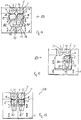
- the goods transport direction runs in the FIGS. 1 to 9 and 11 to 19 left to right.
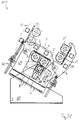
- the goods transport direction also runs in the FIGS. 20 to 25 left to right.
- the calender 100 has a first pivot lever pair 3 and a second pivot lever pair 4.
- Fig. 10 the first pivot lever pair 3 is shown schematically. It can be seen that the swivel lever pair 3 supports the two upper rollers 2, 2 'arranged on both sides on both sides. Fig. 10 also shows that each pivot lever of the pivot lever pair 3 is double-walled.
- the calendar has two similar pairs of pivoting levers 3, 4 and there are exactly two top rollers 2, 2 ', 2 ", 2"' arranged on each of the two pairs of pivot lever.
- Fig. 1 indicates that the pivoting levers 3, 4 are designed as two-armed levers in which on one side of the pivot axis S, S ', the respective top rollers 2, 2', 2 ", 2"'are arranged and on the other side a pivot drive 29th '29' attacks.
- the pivot drive 29, 29 ' comprises a screw jack.
- Each pivot lever is on the pivot axis S, S 'opposite side of a press plane 21, 22 relative to the frame 1 can be fixed.
- Each pivot lever located in working position 9 can be locked on a pivot lever located in parking position 10, in which each pivot lever has a stop surface 11, 11 'pivotally close to its pivot axis S, S' and a stop surface 12, 12 'remote from the pivot axis and the stop surface 11 near the pivot axis , 11 'of the pivot lever located in the parking position 10 rests against the pivot axis remote stop surface 12, 12' of the pivot lever located in the working position 9.
- In the in the FIGS. 1 to 9 shown embodiments is always the left pivot lever in working position. It is understood that the left pivot lever in parking position and the right pivot lever can be in working position.
- Fig. 9 illustrates the pivoting and locking process:
- a first step is a pair of pivot lever (in Fig. 9 the pivot lever pair shown on the right) in a release position 13 can be brought.
- the other pair of pivot levers can be brought into working position.
- the pair of pivot lever from the release position in the park position can be brought, in which its pivot axis near stop surface 11 'on the pivot axis remote abutment surface 12 of the other pair of pivot levers and locks it in this way.
- FIGS. 1 and 9 shows that the parking position 10 of each pivot lever pair is between its release position 13 and its working position 9.
- the calender comprises exactly one lower roller 5 and this is in two different Working positions AU1, AU2 can be brought.
- the lower roller 5 is tiltably arranged to serve the upstream side upper roller 14 or the downstream upper roller 15.
- the lower roller is arranged on a Kipphebelpress 16, the two different end positions 17, 17 ', in each of which a contact surface 18, 18' of the Kipphebelpass rests against a counter-bearing surface 19, 19 'of the frame 1.
- the tilting axis 20 of the rocker arm pair is disposed between the pressing plane 21 of the inlet side nip 8 and the pressing plane 22 of the outlet side nip 8 '(see, for example, FIG Fig. 1 ).
- the movement of the rocker arm pair is about in FIG. 1 , symbolized by the arrow P1.
- the calender comprises exactly two bottom rollers 5, 5 '. These can be delivered independently of each other.
- Each lower roller 5, 5 'shown in the drawings has its own feed device 30, 30', which may comprise a hydraulic cylinder.
- Fig. 5 and 11 the lower roller 5 is shown in two working positions AU1, AU2, one of which is shown in dashed lines.
- the calender 100 comprises a goods feed 23, which comprises a goods transport belt 27.
- this goods conveyor belt 27 is aligned at least substantially horizontally.
- the distance of the goods conveyor belt 27 to the nip 8 ' is relatively large.
- the two top rollers are arranged at the same height in this embodiment.
- the calender 100 is arranged obliquely to make room for the goods conveyor belt 27. As the figure shows, this can be brought closer to the nip 8 ', as by this oblique arrangement, the inlet-side upper roller higher than the outlet-side upper roller is arranged and the inlet-side upper roll thereby provides space for the goods conveyor belt 27.
- the goods conveyor belt 27 is arranged obliquely in the area in front of the nip 8 '. Also in this way it can come closer to the nip, as in the in Fig. 3 shown embodiment. It is a deflection roller 26 is provided which causes a deflection of the goods conveyor belt 27 in the area in front of the nip 8 'upwards.
- the two top rollers are arranged at a height.
- the two top rollers are arranged at two different heights H1, H2.
- the position of the conveyor belt 27 is designed to be variable, depending on whether the inlet-side nip or the outlet-side nip 8 'is realized to be able to come as close as possible to this.
- the goods feeder 23 has an additional transfer belt 24 whose position is changeable.
- Fig. 6 shows a suction roller 25, for transferring the goods on the transfer belt 24th
- the inlet-side lower roller 5 is designed as an alternate lower roller 5a, which can be brought into an evasive position 28.
- the feed device 30 'of this lower roller comprises a telescopic cylinder.
- the conveyor belt or an additional transfer belt can be provided.
- the calender does not comprise any pivot levers with which upper rollers 2, 2 'can be pivoted out of parking positions into working positions. Instead, the top rollers 2, 2 ', as long as they are mounted on the frame 1, always remain in their working position.
- the calender 100 comprises exactly one lower roller 5.
- the calender 100 comprises two lower rollers 5, 5 '.
- the embodiments shown is the lower roller, such as in the in Fig. 1 shown embodiment, arranged on a Kipphebelpress 16, the two different end positions 17, 17 ', on which in each case a contact surface 18, 18' of Kipphebelpass abuts against a counter-bearing surface 19, 19 'of the frame and the pivot axis 20 of Kipphebelpases 16 is between the Pressing plane 21 of the inlet-side nip 8 and the press plane 22 of the outlet-side nip 8 'arranged.
- the lower roller is not pivotable, but slidably disposed to be displaced from the first working position AU1 in the second working position AU2 can.
- it is arranged on a carriage 31 which is displaceable in the direction of the arrow P2.
- the two lower rollers 5, 5 'of in Fig. 13 shown embodiment are deliverable independently. Therefore, as shown in the figure, it is possible to realize two nips 8, 8 'or only the inlet-side nip 8 or only the outlet-side nip 8'.
- the goods conveyor belt 27 at least substantially aligned horizontally and the remaining calender arranged obliquely to make room for this goods conveyor belt 27.
- the two top rollers 2, 2 ' are arranged at a height.
- the inlet-side upper roller 2 creates in the in Fig. 14 shown case in which the outlet-side nip 8 'is realized, space for the goods feed 23, so that the goods conveyor belt 27 as close as possible to the outlet-side nip 8' can reach.
- the two top rollers 2, 2 ' are also arranged at two different heights H1, H2, but with a straight and not obliquely oriented calender, in this respect according to the in FIG Fig. 5 shown embodiment.
- an additional transfer belt 24 is provided which is shown in two different positions and a suction roller 25 transfers the goods from the goods conveyor belt 27 to the transfer belt 24.
- the transfer belt 24 may be coupled to the rocker arm pair 16.
- a guide roller 26 is provided which causes a deflection of the goods conveyor belt 27 in the area in front of the nip 8, 8 'upwards. This is, as with the in Fig. 7 shown embodiment, the inclination of the goods conveyor belt 27 before the nip 8, 8 'changeable without having to change the inclination of the goods conveyor belt before the guide roller 26.
- the inlet-side lower roller 5, as in the in Fig. 8 shown embodiment as a backup roller 5a executed and can pass through an enlarged hub.
- it is equipped with a telescopic cylinder 30a. This allows a deflection, which is greater than the radius of the backup roller 5a.
- the outlet-side nip 8 'space for the goods feed 23 which may include at position 24' the conveyor belt or an additional transfer belt created.
- the calender 100 has exactly one pivot lever pair W, on which two top rollers 2, 2 'are arranged.
- This embodiment has the advantage that later another pair of pivot lever can be retrofitted with additional top rollers.
- the lower roller 5 can be easily removed by swinging the Schwenkhebelpass W, as in the embodiments shown in the FIGS. 11 to 18 are shown, the case is.
- the press planes of the (two) nips run vertically. In the in the FIGS. 4 and 14 and in the Figures 20 and 21 shown embodiments, these press planes are instead inclined. In the in the FIGS. 1 . 3 . 4 . 6 . 7 . 9 . 11 . 14 . 16 . 17 and 19 As shown embodiments, the pivot axis 20 of the Kipphebelbins is centrally located between the inlet-side press plane 21 and the outlet side press plates 22. In the in Fig. 5 In the embodiment shown, the pivot axis 20 is arranged closer to the inlet-side pressing plane 21 than to the outlet-side pressing plane 22.
- the frame 1 is viewed from the side in the in Fig. 1-7 . 9 . 11, 12 . 14 to 17 and 19 shown embodiments formed "U" -shaped.
- the entire frame 1, 101, 10101 is formed stationary.
- the frame 1 has a first stationary frame part OT and a second frame part VT, the second frame part VT being displaceable relative to the first frame part OT.
- the second frame part VT is viewed from the side at least approximately "U" -shaped.
- roller 5 there is exactly one lower roller 5 and this is mounted on the first frame part OT. It is, with the exception of the delivery movement, not relocatable.
- second frame part VT two pairs of pivot lever 3, 4 are mounted, each with two top rollers 2, 2 ', 2 ", 2"'.
- the second frame part VT can be brought into two different positions S1, S2 relative to the first frame part OT, in which the lower roller 5 forms a nip with different top rollers 2, 2 '.
- the second frame part VT is displaceably mounted relative to the first frame part OT by means of a thrust bearing B.
- the thrust bearing B comprises a linear bearing L, thus allowing a straight-line displacement.
- the thrust bearing B includes a carriage and / or rail assembly.
- the thrust bearing B is in the in FIG. 20 shown first position S1 of the second frame part VT completely below the lower roller 5 is arranged. In the in FIG. 21 shown second position S2 of the second frame part VT, it is partially disposed below the lower roller 5.
- the second frame part VT is thus mounted by means of a thrust bearing B slidably on the first frame part OT, which is partially disposed below the lower roller 5, 5 '.
- FIGS. 22 and 23 illustrated as a whole with 10100 designated twenty-first embodiment of the calender according to the invention comprises a frame 101 in which a first roller 102 is arranged.
- the first roller 102 is mounted on a carriage 103, which is displaceable by means of a hydraulically actuated piston / cylinder assembly 104 perpendicular to the longitudinal extent of the roller 101 in the frame, in this case in the vertical direction.
- the piston / cylinder assembly 104 also serves to position the first roller 102 against another roller for nip formation, as will be described below.
- the first roller 102 may be formed as a heated, deflection-controllable roller with a smooth roll shell or in other ways.
- first pivot lever 105 are pivotally mounted about first pivot axes 107.
- the first pivot levers comprise a front, visible in the drawing pivot lever and a distance from this in the direction perpendicular to the plane identical, rear pivot lever, which is not visible in the drawing.
- the following description applies equally to the front, visible first pivot lever 105, as well as the rear pivot lever, although not explicitly mentioned.
- the first pivot levers 105 are designed as two-armed lever.
- a rail arrangement 108 is provided, which serves to attach a second roller 106.
- the second roller 106 is rotatably mounted about its longitudinal axis S2 in a carriage assembly 109 which is displaceable along the rail assembly 108.
- the rail assembly 108 extends along the in FIGS. 22 and 23 shown working position of the first pivot lever each upper edge 1010 and is formed according to the contour of the upper edge as a curved path.
- Linearversteller 1011 The displacement of the carriage assembly 109 along the rail assembly 108 is a Linearversteller 1011, which may be formed as a pneumatically or hydraulically actuated piston / cylinder unit or in any other known manner.
- the one end of the linear adjuster is articulated on the respective first pivot lever 105, the other end on the respective rail arrangement 108.
- a third roller 1012 is mounted rotatably about its longitudinal axis S3 on the carriage arrangement 109.
- the longitudinal axis S3 is spaced from the longitudinal axis S2 by an angular distance ⁇ , which corresponds approximately to the maximum angle a, by which the carriage assembly 109 is displaceable on the rail assembly 108 by means of the linear adjuster 1010.
- pivot drive 1013 which is designed as a screw jack 1014 comprehensive linear drive.
- FIG. 22 an operating state of the calender 10100 is shown in which the first pivot levers 105 are in their working position.
- the second roller 106 as in Figure 22 shown in their working position and forms with the first roller 102 a nip 1015.
- the third roller 1012 is then in its parking position.
- - as in Fig. 23 - The third roller is in its working position and forms with the first roller 102, the nip 1015th Then, the second roller 106 is in its parking position.
- the slide assembly 109 between its in Fig. 22 represented in the first extreme position in which it is based on the graphic representation of the left stop, and their in Fig. 23 shown extreme position in which it is located according to the graphic representation in its right extreme position.
- the first roller can be lowered by means of the piston / cylinder arrangement 104 for the duration of the displacement of the carriage arrangement 109.
- the first pivot lever 105 are - as preferred - briefly raised by means of the rotary actuators 1013.
- the first pivot lever 105 between their in FIGS. 22 and 23 shown working positions in which the upper edges 1016 extend approximately parallel to the lower edge 1017 of the frame 101, and parking positions in which the upper edges 1016 extend approximately perpendicular to the lower edge 1017 to shift.
- these parking positions both the first roller 102, and the second and the third roller from the outside are easily accessible, which is for example for the purpose of replacement or maintenance of great advantage.
- the embodiment of the calender 10100 according to the invention also has second pivot levers 1018, which are mounted on the frame 101 so as to be pivotable about second pivot axes 1019.
- the second pivot lever 1018 are with respect to the plane E, which is defined by the two longitudinal axes of the nip forming rollers, arranged in mirror image to the first pivot lever 105 on the frame 1 and also formed in mirror image to the first pivot lever 105. Accordingly, the second pivot lever 1018 are again designed as a two-armed lever.
- the respective first arm 1018 'of the second pivoting levers 1018 comprises, analogously to the construction of the first pivoting levers 105, a recess with an upper edge 1026 in the working position, which is curved and along which a rail arrangement 1027 extends.
- a slide arrangement 1028 is again provided displaceably along the curved path predetermined by the rail arrangement.
- the shift serves one at each of the second Swivel lever 1018 provided linear adjuster 1029, which in turn may be formed, for example, as a hydraulic or pneumatic piston / cylinder unit or in any other way.
- the carriage arrangement serves to support a fourth roller 1030 and a fifth roller 1031 in a manner corresponding to the bearing of the second roller 106 and third roller 1012.
- the fourth roller 1030 or the fifth roller 1031 can optionally be displaced into their respective parking position and into their respective working position with the aid of the linear adjuster 1029. This is analogous to the second roller 106 and third roller 1012, after the nip has been briefly opened by lowering the first roller 102 or slight pivoting of the second pivot lever 1018.
- the first and second pivot lever 105 pivot axis near locking means 1032 and pivot axis remote locking means 1033 on.
- the locking means are arranged and designed such that the pivot axis near locking of each located in their parking position pivot lever overlap the pivot axis remote locking means 1033 located in their working positions pivot lever and thus acting on the located in their working position swivel bracket reaction forces also on the pivot axes and the linear adjuster of their parking position located pivot lever are introduced into the frame.
- a first roller 10102 is arranged in a frame 10101. It is mounted on a carriage 10103, which by means of a hydraulically actuated piston / cylinder assembly 10104 vertically to the longitudinal extent of the roller 10102 in the frame 10101 is displaceable, in this case in the vertical direction.
- the piston / cylinder arrangement 10104 in turn also serves to set the first roller 10102 against another roller for the purpose of nip formation, as will be described below.
- the first roll 10102 may be formed as a heated, deflection-controllable roll with a smooth roll shell or in some other way.
- first pivot levers 10105 are provided, of which only the front pivot lever facing the viewer can be seen in the drawing.
- the first pivot levers 10105 are for supporting a second roller 10106 and a third roller 10112 at one end thereof, respectively.
- the first pivot levers 10105 are pivotally mounted about a first pivot axis 10107 on the frame 10101, in such a way that it either in one of the in Fig. 24 are located in which either the second roller 10106, or - as in the in Fig. 24 shown in solid line - the third roller 10112 with the first roller 10102 forms a nip 10115 or in a rest position, in which the second and the third roller to the first roller are spaced.
- first pivot lever 10105 are designed as two-armed lever, wherein on the first arm 10105 'the second and third rollers 10106, 10112 are mounted and at the end of the second arm 10105 "a pivot drive 10113 attacks, which in turn is mounted on the frame 10101.
- the pivot drive comprises a screw jack 10114.
- the third roller 10112 is in its working position and forms with the first roller 10102 the nip 10115th
- the first pivot lever are not only with the aid of the pivot drive 10113 about its first pivot axes 10107 pivotally mounted on the frame 10101, but the first pivot axes 10107 are relative to Rack 10101 arranged displaceable.
- the bearing side bearing blocks comprehensive storage facilities 10108 which define the positions of the pivot axes 10107 of the first pivot lever 10105, is provided, the storage facilities 10108 along each rail assembly 10109 by means of linear Verstellers not shown in the drawing are displaced.
- the rail assembly 10109 is oriented upward from the nip 10115 seen.
- the pivot axes 10107 of the first pivot lever 10105 are displaced in a further displacement of the nip 10115 also with a vertical component, whereby the third roller 10112 is displaced during displacement from the working in a parking position with a vertically upward movement component.
- the pivot drive 10113 is synchronously actuated until the first pivot levers 10105, the in Fig. 24 in the left-hand dotted line, in which the third roller 10112 is in a parking position and the second roller 10106 is in a working position in which it forms the nip 10115 with the first roller 10102.
- either the first roller can be lowered by means of the piston / cylinder arrangement 10104 for the duration of the displacement of the pivot axes 10107.
- the 10105 swivel levers are raised briefly with the help of the 10113 quarter-turn actuators.
- a change of in Fig. 25 shown web guide, in particular Relocation of the guide roller 1024 of the web conveying 1025 is then not required.
- the second embodiment of the calender 10200 further comprises to the plane E, which is defined by the longitudinal axes of the two rolls forming the nip 10115 mirrored to the first pivoting levers 10105 and second mirrored to the frame 10101 second pivot lever 10118.
- a fourth roller 10130 and a fifth roller 10131 are mounted on the first arm 10118th.
- the second arm 10118 "is engaged by a second pivot drive 10120 which comprises a second screw jack 10121.
- a separate second pivot drive 10120 is provided for each second pivot lever 10118.
- the respective pivot lever is mounted about a second pivot axis 10119 between the pivot axis Fig. 24 illustrated parking position and working positions, which - mirror images - correspond to those in which the first pivot lever 10105 are shown, pivotable.
- a second bearing device 10127 comprising a bearing block is provided, which in turn can be displaced along a second rail arrangement 10128 with the aid of a linear adjuster, not shown in the drawing. Since the bearing device 10127 defines the second pivot axis 10119, and the second rail assembly 10128 is aligned with the plane E mirror image of the rail assembly 10109, a change between the fourth and the fifth roll can be analogous to the change between the second and the third roller. It is understood that previously the first pivot lever 10105 must be moved to their parking positions, which - again mirrored to the plane E - the in Fig. 24 Park positions represented the second pivot lever 10118 correspond.
- All pivot levers 105, 1018; 10105, 10118 are designed as double-walled lever and engage around a bearing lug of the frame 101, 10101 on both sides.
- a very stable storage of the respective pivot lever is achieved in the frame, which is a tilting of the pivot lever relative to the frame in a direction other than the pivoting movement reliably prevented.
- each pivot lever of a pair rotatably receiving the roller in one of its two end portions.
- the unrecognizable pivot lever of each pivot lever pair have the same configurations as the recognizable pivot lever.
- the same storage facilities and part-turn actuators, rail arrangements and linear adjusters are provided for the unrecognizable swivel lever pairs.
- a to be treated by means of the calender according to the invention web can be passed between the two pivot levers of a pair of pivot levers and it can so in Fig. 25 shown schematically web guide can be realized.
- a web 10W for example in the form of a layer of filaments, between the first roller 102 and one of the second to fifth rollers 106, 1012, 1030, 1031; 10106, 10112, 10130, 10131 formed nip 1015, 10115 supplied and solidified in this.
- suitable cooling rollers 1023 the web is fed in the forward direction V for further use.
- the web guide it is ensured that the web leaves the nip without further contact with the rollers, whereby a thermal damage to the non-solidifying areas is avoided. Also, due to the arrangement of the guide roller 1024 in the immediate vicinity of the nip and with its horizontal tangent above the nip ensured that the unconsolidated goods - fixed on the conveyor belt - can be brought as close to the nip. Finally, the web feed takes place almost parallel to the plane in which the nip is located (nip plane), so that the deflecting roller 1024 is only looped around by a small angle. Due to this measure, the risk of the goods sticking to the screen belt 1022 and tearing is reduced. With the plane in which the nip is located (Nipebene), is referred to in the context of this document in particular the plane perpendicular to the press plane of a nip plane.
- the supply of the bearings with lubricant is to accomplish in a simple manner. Because due to the arrangement of alternatively usable for nip formation second to fifth rolls of pivoting levers, the bearing body only by angle ⁇ 180 °, depending on the design of the pivot lever only by angle ⁇ 150 °, ⁇ 120 ° or even ⁇ 90 ° at a shift between working - and parking position twisted. This is a great advantage, in particular in the case of bearing lubrication without contacting seals and, consequently, pressureless, gravity-only oil drainage, as conventionally used in heated rolls. Bearing lubricating oil drains and return lines with gravity feed are thus easily executable.
- rollers are rotatably drivable in their parking position. Because especially at elevated roller temperatures, especially at roller temperatures> 80 ° C, the rollers must be rotated continuously to avoid permanent deformation.
- all rollers, at least the second to fifth rollers can be provided with their own rotary drives, which are not recognizable in the drawing. Its own rotary drives also make any otherwise necessary coupling and uncoupling of a common rotary drive unnecessary. So that separate drive blocks for the own rotary drives with the rollers do not have to be moved, it is advantageous if the own rotary actuators are designed as "direct drives".
- first and second pivoting lever with the associated second and third and fourth and fifth rollers have first and second pivoting lever with the associated second and third and fourth and fifth rollers. According to the invention, however, are also embodiments in which only the first pivot lever with the second and third rollers are present, especially if these embodiments are suitable to be supplemented with second pivot lever with fourth and fifth rollers.
Landscapes
- Engineering & Computer Science (AREA)
- Textile Engineering (AREA)
- Casting Or Compression Moulding Of Plastics Or The Like (AREA)
- Treatment Of Fiber Materials (AREA)
- Paper (AREA)
- Rolls And Other Rotary Bodies (AREA)
Applications Claiming Priority (4)
| Application Number | Priority Date | Filing Date | Title |
|---|---|---|---|
| DE102014113755.8A DE102014113755A1 (de) | 2014-09-23 | 2014-09-23 | Kalander |
| DE102015107839.2A DE102015107839B3 (de) | 2015-05-19 | 2015-05-19 | Kalander |
| PCT/EP2015/071156 WO2016046030A2 (fr) | 2014-09-23 | 2015-09-16 | Calandre |
| EP15763343.9A EP3198070B1 (fr) | 2014-09-23 | 2015-09-16 | Calandre |
Related Parent Applications (2)
| Application Number | Title | Priority Date | Filing Date |
|---|---|---|---|
| EP15763343.9A Division EP3198070B1 (fr) | 2014-09-23 | 2015-09-16 | Calandre |
| EP15763343.9A Division-Into EP3198070B1 (fr) | 2014-09-23 | 2015-09-16 | Calandre |
Publications (3)
| Publication Number | Publication Date |
|---|---|
| EP3415676A2 true EP3415676A2 (fr) | 2018-12-19 |
| EP3415676A3 EP3415676A3 (fr) | 2019-01-02 |
| EP3415676B1 EP3415676B1 (fr) | 2023-07-19 |
Family
ID=54106373
Family Applications (2)
| Application Number | Title | Priority Date | Filing Date |
|---|---|---|---|
| EP15763343.9A Not-in-force EP3198070B1 (fr) | 2014-09-23 | 2015-09-16 | Calandre |
| EP18181952.5A Active EP3415676B1 (fr) | 2014-09-23 | 2015-09-16 | Calendre |
Family Applications Before (1)
| Application Number | Title | Priority Date | Filing Date |
|---|---|---|---|
| EP15763343.9A Not-in-force EP3198070B1 (fr) | 2014-09-23 | 2015-09-16 | Calandre |
Country Status (2)
| Country | Link |
|---|---|
| EP (2) | EP3198070B1 (fr) |
| WO (1) | WO2016046030A2 (fr) |
Families Citing this family (3)
| Publication number | Priority date | Publication date | Assignee | Title |
|---|---|---|---|---|
| DE102017107120A1 (de) * | 2017-04-03 | 2018-10-04 | Andritz Küsters Gmbh | Verfahren und Vorrichtung zur Behandlung einer Warenbahn |
| IT202200011375A1 (it) | 2022-05-30 | 2023-11-30 | Ramina S R L | Macchina per la calandratura |
| AT526199B1 (de) * | 2022-05-31 | 2025-10-15 | Andritz Hydro Gmbh | Schütz für eine Wasserkraftanlage |
Family Cites Families (9)
| Publication number | Priority date | Publication date | Assignee | Title |
|---|---|---|---|---|
| US3244090A (en) * | 1964-09-01 | 1966-04-05 | Perkins & Son Inc B F | Calender |
| AT370347B (de) * | 1981-03-24 | 1983-03-25 | Voest Alpine Ag | Walzgeruest |
| DE3712276C1 (en) * | 1987-04-10 | 1988-10-27 | Kuesters Eduard Maschf | Fleece calender |
| FI86092C (fi) * | 1989-11-27 | 1992-07-10 | Valmet Paper Machinery Inc | Kalander avsedd foer on-line anslutning till en pappersmaskin. |
| JPH07258992A (ja) * | 1994-03-17 | 1995-10-09 | Nippon Paper Ind Co Ltd | 製紙用カレンダ装置 |
| DE4412862C1 (de) * | 1994-04-14 | 1995-08-10 | Berstorff Gmbh Masch Hermann | Walzenwechselvorrichtung an einem Kalander |
| DE10005306C1 (de) * | 2000-02-07 | 2001-06-13 | Kleinewefers Textilmaschinen G | Kalander, insbesondere für textile, Vlies- oder Kunststoff-Warenbahnen |
| DE10310468A1 (de) * | 2003-03-11 | 2004-09-23 | Thyssenkrupp Elastomertechnik Gmbh | Vorrichtung zum Wechseln von Walzen an Kalandern |
| DE10348900B4 (de) * | 2003-10-16 | 2006-03-09 | Palamides Gmbh | Vorrichtung zum Pressen von flächigen Druckereierzeugnissen |
-
2015
- 2015-09-16 EP EP15763343.9A patent/EP3198070B1/fr not_active Not-in-force
- 2015-09-16 EP EP18181952.5A patent/EP3415676B1/fr active Active
- 2015-09-16 WO PCT/EP2015/071156 patent/WO2016046030A2/fr not_active Ceased
Also Published As
| Publication number | Publication date |
|---|---|
| EP3415676A3 (fr) | 2019-01-02 |
| EP3198070A2 (fr) | 2017-08-02 |
| EP3415676B1 (fr) | 2023-07-19 |
| WO2016046030A2 (fr) | 2016-03-31 |
| WO2016046030A3 (fr) | 2016-06-16 |
| EP3198070B1 (fr) | 2018-11-21 |
Similar Documents
| Publication | Publication Date | Title |
|---|---|---|
| DE3305429C2 (de) | Kalander zur Druck- und Wärmebehandlung von Warenbahnen | |
| EP1130159B1 (fr) | Calandre | |
| EP3108058B1 (fr) | Calandre à remplacement rapide | |
| DE4035986C2 (de) | Kalander für den On-line-Anschluß an eine Papiermaschine | |
| EP3198070B1 (fr) | Calandre | |
| DE1461220A1 (de) | Justiervorrichtung an einer Rotationsmaschine | |
| EP3150291B1 (fr) | Procede et dispositif destines au refroidissement d'un cylindre dispose dans une cage de laminoir | |
| DE102014113755A1 (de) | Kalander | |
| DE102015106045B3 (de) | Kalander | |
| DE102015107839B3 (de) | Kalander | |
| DE3712276C1 (en) | Fleece calender | |
| EP1763425B1 (fr) | Procede pour faire fonctionner une machine de polissage a quatre cylindres | |
| EP3738740B1 (fr) | Dispositif de formation transversale d'une pluralité de faisceaux de fibres plastique parallèles | |
| DE8817076U1 (de) | Kalander | |
| WO1990007417A1 (fr) | Calandre a estamper | |
| DE2060540C3 (de) | Schrägwalzwerk zur Herstellung nahtloser Rohre bzw. Luppen | |
| DE904150C (de) | Walzvorrichtung, insbesondere Florquetsche | |
| WO2015132302A1 (fr) | Presse à cylindres | |
| DE864844C (de) | Zur Lenkung laufenden Walzgutes, insbesondere von Walzbaendern, zwischen die Arbeitswalzen von Walzwerken dienender, in Walz-richtung verschiebbarer Einfuehrtisch | |
| AT504422B1 (de) | Gelenklagerung einer durchbiegungseinstellwalze einer papier-, karton- oder ausrüstungsmaschine | |
| WO2009149914A1 (fr) | Laminoir à cylindres réglables conçu pour former des pièces métalliques et/ou contenant du fer | |
| EP3607138B1 (fr) | Procédé et dispositif de traitement d'une bande de matière | |
| DE1817680B2 (de) | Gußwalzenanordnung zur Herstellung von-Walzglas | |
| EP2560770B1 (fr) | Laminoir a feuillards pour laminer a froid une bande metallique avec un mecanisme de compression | |
| EP4640397A1 (fr) | Appareil de lissage |
Legal Events
| Date | Code | Title | Description |
|---|---|---|---|
| PUAI | Public reference made under article 153(3) epc to a published international application that has entered the european phase |
Free format text: ORIGINAL CODE: 0009012 |
|
| STAA | Information on the status of an ep patent application or granted ep patent |
Free format text: STATUS: THE APPLICATION HAS BEEN PUBLISHED |
|
| PUAL | Search report despatched |
Free format text: ORIGINAL CODE: 0009013 |
|
| AC | Divisional application: reference to earlier application |
Ref document number: 3198070 Country of ref document: EP Kind code of ref document: P |
|
| AK | Designated contracting states |
Kind code of ref document: A2 Designated state(s): AL AT BE BG CH CY CZ DE DK EE ES FI FR GB GR HR HU IE IS IT LI LT LU LV MC MK MT NL NO PL PT RO RS SE SI SK SM TR |
|
| AK | Designated contracting states |
Kind code of ref document: A3 Designated state(s): AL AT BE BG CH CY CZ DE DK EE ES FI FR GB GR HR HU IE IS IT LI LT LU LV MC MK MT NL NO PL PT RO RS SE SI SK SM TR |
|
| RIC1 | Information provided on ipc code assigned before grant |
Ipc: D21G 1/00 20060101ALI20181126BHEP Ipc: D21G 1/02 20060101ALI20181126BHEP Ipc: D06C 15/02 20060101AFI20181126BHEP |
|
| STAA | Information on the status of an ep patent application or granted ep patent |
Free format text: STATUS: REQUEST FOR EXAMINATION WAS MADE |
|
| 17P | Request for examination filed |
Effective date: 20190617 |
|
| RBV | Designated contracting states (corrected) |
Designated state(s): AL AT BE BG CH CY CZ DE DK EE ES FI FR GB GR HR HU IE IS IT LI LT LU LV MC MK MT NL NO PL PT RO RS SE SI SK SM TR |
|
| STAA | Information on the status of an ep patent application or granted ep patent |
Free format text: STATUS: EXAMINATION IS IN PROGRESS |
|
| 17Q | First examination report despatched |
Effective date: 20210601 |
|
| GRAP | Despatch of communication of intention to grant a patent |
Free format text: ORIGINAL CODE: EPIDOSNIGR1 |
|
| STAA | Information on the status of an ep patent application or granted ep patent |
Free format text: STATUS: GRANT OF PATENT IS INTENDED |
|
| INTG | Intention to grant announced |
Effective date: 20230215 |
|
| GRAS | Grant fee paid |
Free format text: ORIGINAL CODE: EPIDOSNIGR3 |
|
| GRAA | (expected) grant |
Free format text: ORIGINAL CODE: 0009210 |
|
| STAA | Information on the status of an ep patent application or granted ep patent |
Free format text: STATUS: THE PATENT HAS BEEN GRANTED |
|
| P01 | Opt-out of the competence of the unified patent court (upc) registered |
Effective date: 20230524 |
|
| AC | Divisional application: reference to earlier application |
Ref document number: 3198070 Country of ref document: EP Kind code of ref document: P |
|
| AK | Designated contracting states |
Kind code of ref document: B1 Designated state(s): AL AT BE BG CH CY CZ DE DK EE ES FI FR GB GR HR HU IE IS IT LI LT LU LV MC MK MT NL NO PL PT RO RS SE SI SK SM TR |
|
| REG | Reference to a national code |
Ref country code: GB Ref legal event code: FG4D Free format text: NOT ENGLISH |
|
| REG | Reference to a national code |
Ref country code: CH Ref legal event code: EP |
|
| REG | Reference to a national code |
Ref country code: DE Ref legal event code: R096 Ref document number: 502015016502 Country of ref document: DE |
|
| REG | Reference to a national code |
Ref country code: IE Ref legal event code: FG4D Free format text: LANGUAGE OF EP DOCUMENT: GERMAN |
|
| REG | Reference to a national code |
Ref country code: LT Ref legal event code: MG9D |
|
| REG | Reference to a national code |
Ref country code: NL Ref legal event code: MP Effective date: 20230719 |
|
| PG25 | Lapsed in a contracting state [announced via postgrant information from national office to epo] |
Ref country code: NL Free format text: LAPSE BECAUSE OF FAILURE TO SUBMIT A TRANSLATION OF THE DESCRIPTION OR TO PAY THE FEE WITHIN THE PRESCRIBED TIME-LIMIT Effective date: 20230719 |
|
| PG25 | Lapsed in a contracting state [announced via postgrant information from national office to epo] |
Ref country code: GR Free format text: LAPSE BECAUSE OF FAILURE TO SUBMIT A TRANSLATION OF THE DESCRIPTION OR TO PAY THE FEE WITHIN THE PRESCRIBED TIME-LIMIT Effective date: 20231020 |
|
| PG25 | Lapsed in a contracting state [announced via postgrant information from national office to epo] |
Ref country code: IS Free format text: LAPSE BECAUSE OF FAILURE TO SUBMIT A TRANSLATION OF THE DESCRIPTION OR TO PAY THE FEE WITHIN THE PRESCRIBED TIME-LIMIT Effective date: 20231119 |
|
| PG25 | Lapsed in a contracting state [announced via postgrant information from national office to epo] |
Ref country code: SE Free format text: LAPSE BECAUSE OF FAILURE TO SUBMIT A TRANSLATION OF THE DESCRIPTION OR TO PAY THE FEE WITHIN THE PRESCRIBED TIME-LIMIT Effective date: 20230719 Ref country code: RS Free format text: LAPSE BECAUSE OF FAILURE TO SUBMIT A TRANSLATION OF THE DESCRIPTION OR TO PAY THE FEE WITHIN THE PRESCRIBED TIME-LIMIT Effective date: 20230719 Ref country code: PT Free format text: LAPSE BECAUSE OF FAILURE TO SUBMIT A TRANSLATION OF THE DESCRIPTION OR TO PAY THE FEE WITHIN THE PRESCRIBED TIME-LIMIT Effective date: 20231120 Ref country code: NO Free format text: LAPSE BECAUSE OF FAILURE TO SUBMIT A TRANSLATION OF THE DESCRIPTION OR TO PAY THE FEE WITHIN THE PRESCRIBED TIME-LIMIT Effective date: 20231019 Ref country code: LV Free format text: LAPSE BECAUSE OF FAILURE TO SUBMIT A TRANSLATION OF THE DESCRIPTION OR TO PAY THE FEE WITHIN THE PRESCRIBED TIME-LIMIT Effective date: 20230719 Ref country code: LT Free format text: LAPSE BECAUSE OF FAILURE TO SUBMIT A TRANSLATION OF THE DESCRIPTION OR TO PAY THE FEE WITHIN THE PRESCRIBED TIME-LIMIT Effective date: 20230719 Ref country code: IS Free format text: LAPSE BECAUSE OF FAILURE TO SUBMIT A TRANSLATION OF THE DESCRIPTION OR TO PAY THE FEE WITHIN THE PRESCRIBED TIME-LIMIT Effective date: 20231119 Ref country code: HR Free format text: LAPSE BECAUSE OF FAILURE TO SUBMIT A TRANSLATION OF THE DESCRIPTION OR TO PAY THE FEE WITHIN THE PRESCRIBED TIME-LIMIT Effective date: 20230719 Ref country code: GR Free format text: LAPSE BECAUSE OF FAILURE TO SUBMIT A TRANSLATION OF THE DESCRIPTION OR TO PAY THE FEE WITHIN THE PRESCRIBED TIME-LIMIT Effective date: 20231020 Ref country code: FI Free format text: LAPSE BECAUSE OF FAILURE TO SUBMIT A TRANSLATION OF THE DESCRIPTION OR TO PAY THE FEE WITHIN THE PRESCRIBED TIME-LIMIT Effective date: 20230719 |
|
| PG25 | Lapsed in a contracting state [announced via postgrant information from national office to epo] |
Ref country code: PL Free format text: LAPSE BECAUSE OF FAILURE TO SUBMIT A TRANSLATION OF THE DESCRIPTION OR TO PAY THE FEE WITHIN THE PRESCRIBED TIME-LIMIT Effective date: 20230719 |
|
| REG | Reference to a national code |
Ref country code: DE Ref legal event code: R097 Ref document number: 502015016502 Country of ref document: DE |
|
| PG25 | Lapsed in a contracting state [announced via postgrant information from national office to epo] |
Ref country code: ES Free format text: LAPSE BECAUSE OF FAILURE TO SUBMIT A TRANSLATION OF THE DESCRIPTION OR TO PAY THE FEE WITHIN THE PRESCRIBED TIME-LIMIT Effective date: 20230719 |
|
| PG25 | Lapsed in a contracting state [announced via postgrant information from national office to epo] |
Ref country code: SM Free format text: LAPSE BECAUSE OF FAILURE TO SUBMIT A TRANSLATION OF THE DESCRIPTION OR TO PAY THE FEE WITHIN THE PRESCRIBED TIME-LIMIT Effective date: 20230719 Ref country code: RO Free format text: LAPSE BECAUSE OF FAILURE TO SUBMIT A TRANSLATION OF THE DESCRIPTION OR TO PAY THE FEE WITHIN THE PRESCRIBED TIME-LIMIT Effective date: 20230719 Ref country code: ES Free format text: LAPSE BECAUSE OF FAILURE TO SUBMIT A TRANSLATION OF THE DESCRIPTION OR TO PAY THE FEE WITHIN THE PRESCRIBED TIME-LIMIT Effective date: 20230719 Ref country code: EE Free format text: LAPSE BECAUSE OF FAILURE TO SUBMIT A TRANSLATION OF THE DESCRIPTION OR TO PAY THE FEE WITHIN THE PRESCRIBED TIME-LIMIT Effective date: 20230719 Ref country code: DK Free format text: LAPSE BECAUSE OF FAILURE TO SUBMIT A TRANSLATION OF THE DESCRIPTION OR TO PAY THE FEE WITHIN THE PRESCRIBED TIME-LIMIT Effective date: 20230719 Ref country code: CZ Free format text: LAPSE BECAUSE OF FAILURE TO SUBMIT A TRANSLATION OF THE DESCRIPTION OR TO PAY THE FEE WITHIN THE PRESCRIBED TIME-LIMIT Effective date: 20230719 Ref country code: SK Free format text: LAPSE BECAUSE OF FAILURE TO SUBMIT A TRANSLATION OF THE DESCRIPTION OR TO PAY THE FEE WITHIN THE PRESCRIBED TIME-LIMIT Effective date: 20230719 |
|
| REG | Reference to a national code |
Ref country code: CH Ref legal event code: PL |
|
| PG25 | Lapsed in a contracting state [announced via postgrant information from national office to epo] |
Ref country code: LU Free format text: LAPSE BECAUSE OF NON-PAYMENT OF DUE FEES Effective date: 20230916 |
|
| PLBE | No opposition filed within time limit |
Free format text: ORIGINAL CODE: 0009261 |
|
| STAA | Information on the status of an ep patent application or granted ep patent |
Free format text: STATUS: NO OPPOSITION FILED WITHIN TIME LIMIT |
|
| REG | Reference to a national code |
Ref country code: BE Ref legal event code: MM Effective date: 20230930 |
|
| PG25 | Lapsed in a contracting state [announced via postgrant information from national office to epo] |
Ref country code: LU Free format text: LAPSE BECAUSE OF NON-PAYMENT OF DUE FEES Effective date: 20230916 Ref country code: MC Free format text: LAPSE BECAUSE OF FAILURE TO SUBMIT A TRANSLATION OF THE DESCRIPTION OR TO PAY THE FEE WITHIN THE PRESCRIBED TIME-LIMIT Effective date: 20230719 |
|
| 26N | No opposition filed |
Effective date: 20240422 |
|
| GBPC | Gb: european patent ceased through non-payment of renewal fee |
Effective date: 20231019 |
|
| REG | Reference to a national code |
Ref country code: IE Ref legal event code: MM4A |
|
| PG25 | Lapsed in a contracting state [announced via postgrant information from national office to epo] |
Ref country code: IE Free format text: LAPSE BECAUSE OF NON-PAYMENT OF DUE FEES Effective date: 20230916 |
|
| PG25 | Lapsed in a contracting state [announced via postgrant information from national office to epo] |
Ref country code: GB Free format text: LAPSE BECAUSE OF NON-PAYMENT OF DUE FEES Effective date: 20231019 |
|
| PG25 | Lapsed in a contracting state [announced via postgrant information from national office to epo] |
Ref country code: CH Free format text: LAPSE BECAUSE OF NON-PAYMENT OF DUE FEES Effective date: 20230930 |
|
| PG25 | Lapsed in a contracting state [announced via postgrant information from national office to epo] |
Ref country code: IE Free format text: LAPSE BECAUSE OF NON-PAYMENT OF DUE FEES Effective date: 20230916 Ref country code: GB Free format text: LAPSE BECAUSE OF NON-PAYMENT OF DUE FEES Effective date: 20231019 Ref country code: FR Free format text: LAPSE BECAUSE OF NON-PAYMENT OF DUE FEES Effective date: 20230919 Ref country code: CH Free format text: LAPSE BECAUSE OF NON-PAYMENT OF DUE FEES Effective date: 20230930 Ref country code: SI Free format text: LAPSE BECAUSE OF FAILURE TO SUBMIT A TRANSLATION OF THE DESCRIPTION OR TO PAY THE FEE WITHIN THE PRESCRIBED TIME-LIMIT Effective date: 20230719 |
|
| PG25 | Lapsed in a contracting state [announced via postgrant information from national office to epo] |
Ref country code: BE Free format text: LAPSE BECAUSE OF NON-PAYMENT OF DUE FEES Effective date: 20230930 |
|
| PG25 | Lapsed in a contracting state [announced via postgrant information from national office to epo] |
Ref country code: BG Free format text: LAPSE BECAUSE OF FAILURE TO SUBMIT A TRANSLATION OF THE DESCRIPTION OR TO PAY THE FEE WITHIN THE PRESCRIBED TIME-LIMIT Effective date: 20230719 |
|
| REG | Reference to a national code |
Ref country code: AT Ref legal event code: MM01 Ref document number: 1589562 Country of ref document: AT Kind code of ref document: T Effective date: 20230916 |
|
| PG25 | Lapsed in a contracting state [announced via postgrant information from national office to epo] |
Ref country code: BG Free format text: LAPSE BECAUSE OF FAILURE TO SUBMIT A TRANSLATION OF THE DESCRIPTION OR TO PAY THE FEE WITHIN THE PRESCRIBED TIME-LIMIT Effective date: 20230719 |
|
| PG25 | Lapsed in a contracting state [announced via postgrant information from national office to epo] |
Ref country code: AT Free format text: LAPSE BECAUSE OF NON-PAYMENT OF DUE FEES Effective date: 20230916 |
|
| PG25 | Lapsed in a contracting state [announced via postgrant information from national office to epo] |
Ref country code: AT Free format text: LAPSE BECAUSE OF NON-PAYMENT OF DUE FEES Effective date: 20230916 |
|
| PG25 | Lapsed in a contracting state [announced via postgrant information from national office to epo] |
Ref country code: CY Free format text: LAPSE BECAUSE OF FAILURE TO SUBMIT A TRANSLATION OF THE DESCRIPTION OR TO PAY THE FEE WITHIN THE PRESCRIBED TIME-LIMIT; INVALID AB INITIO Effective date: 20150916 |
|
| PG25 | Lapsed in a contracting state [announced via postgrant information from national office to epo] |
Ref country code: HU Free format text: LAPSE BECAUSE OF FAILURE TO SUBMIT A TRANSLATION OF THE DESCRIPTION OR TO PAY THE FEE WITHIN THE PRESCRIBED TIME-LIMIT; INVALID AB INITIO Effective date: 20150916 |
|
| PGFP | Annual fee paid to national office [announced via postgrant information from national office to epo] |
Ref country code: DE Payment date: 20250930 Year of fee payment: 11 |
|
| PG25 | Lapsed in a contracting state [announced via postgrant information from national office to epo] |
Ref country code: TR Free format text: LAPSE BECAUSE OF FAILURE TO SUBMIT A TRANSLATION OF THE DESCRIPTION OR TO PAY THE FEE WITHIN THE PRESCRIBED TIME-LIMIT Effective date: 20230719 |
|
| PGFP | Annual fee paid to national office [announced via postgrant information from national office to epo] |
Ref country code: IT Payment date: 20250930 Year of fee payment: 11 |