EP3415733A1 - Capteur de qualité de fluide pour mesurer la qualité d'un fluide, ensemble capteur et ensemble pour moteurs à combustion interne comprenant un capteur de qualité de fluides - Google Patents
Capteur de qualité de fluide pour mesurer la qualité d'un fluide, ensemble capteur et ensemble pour moteurs à combustion interne comprenant un capteur de qualité de fluides Download PDFInfo
- Publication number
- EP3415733A1 EP3415733A1 EP17305723.3A EP17305723A EP3415733A1 EP 3415733 A1 EP3415733 A1 EP 3415733A1 EP 17305723 A EP17305723 A EP 17305723A EP 3415733 A1 EP3415733 A1 EP 3415733A1
- Authority
- EP
- European Patent Office
- Prior art keywords
- fluid
- sensor
- assembly
- pump
- quality sensor
- Prior art date
- Legal status (The legal status is an assumption and is not a legal conclusion. Google has not performed a legal analysis and makes no representation as to the accuracy of the status listed.)
- Withdrawn
Links
Images



Classifications
-
- G—PHYSICS
- G01—MEASURING; TESTING
- G01M—TESTING STATIC OR DYNAMIC BALANCE OF MACHINES OR STRUCTURES; TESTING OF STRUCTURES OR APPARATUS, NOT OTHERWISE PROVIDED FOR
- G01M15/00—Testing of engines
- G01M15/04—Testing internal-combustion engines
- G01M15/10—Testing internal-combustion engines by monitoring exhaust gases or combustion flame
- G01M15/102—Testing internal-combustion engines by monitoring exhaust gases or combustion flame by monitoring exhaust gases
- G01M15/108—Testing internal-combustion engines by monitoring exhaust gases or combustion flame by monitoring exhaust gases using optical methods
-
- F—MECHANICAL ENGINEERING; LIGHTING; HEATING; WEAPONS; BLASTING
- F01—MACHINES OR ENGINES IN GENERAL; ENGINE PLANTS IN GENERAL; STEAM ENGINES
- F01N—GAS-FLOW SILENCERS OR EXHAUST APPARATUS FOR MACHINES OR ENGINES IN GENERAL; GAS-FLOW SILENCERS OR EXHAUST APPARATUS FOR INTERNAL-COMBUSTION ENGINES
- F01N11/00—Monitoring or diagnostic devices for exhaust-gas treatment apparatus
-
- F—MECHANICAL ENGINEERING; LIGHTING; HEATING; WEAPONS; BLASTING
- F01—MACHINES OR ENGINES IN GENERAL; ENGINE PLANTS IN GENERAL; STEAM ENGINES
- F01N—GAS-FLOW SILENCERS OR EXHAUST APPARATUS FOR MACHINES OR ENGINES IN GENERAL; GAS-FLOW SILENCERS OR EXHAUST APPARATUS FOR INTERNAL-COMBUSTION ENGINES
- F01N13/00—Exhaust or silencing apparatus characterised by constructional features
- F01N13/008—Mounting or arrangement of exhaust sensors in or on exhaust apparatus
-
- F—MECHANICAL ENGINEERING; LIGHTING; HEATING; WEAPONS; BLASTING
- F01—MACHINES OR ENGINES IN GENERAL; ENGINE PLANTS IN GENERAL; STEAM ENGINES
- F01N—GAS-FLOW SILENCERS OR EXHAUST APPARATUS FOR MACHINES OR ENGINES IN GENERAL; GAS-FLOW SILENCERS OR EXHAUST APPARATUS FOR INTERNAL-COMBUSTION ENGINES
- F01N3/00—Exhaust or silencing apparatus having means for purifying, rendering innocuous, or otherwise treating exhaust
- F01N3/08—Exhaust or silencing apparatus having means for purifying, rendering innocuous, or otherwise treating exhaust for rendering innocuous
- F01N3/10—Exhaust or silencing apparatus having means for purifying, rendering innocuous, or otherwise treating exhaust for rendering innocuous by thermal or catalytic conversion of noxious components of exhaust
- F01N3/18—Exhaust or silencing apparatus having means for purifying, rendering innocuous, or otherwise treating exhaust for rendering innocuous by thermal or catalytic conversion of noxious components of exhaust characterised by methods of operation; Control
- F01N3/20—Exhaust or silencing apparatus having means for purifying, rendering innocuous, or otherwise treating exhaust for rendering innocuous by thermal or catalytic conversion of noxious components of exhaust characterised by methods of operation; Control specially adapted for catalytic conversion
- F01N3/206—Adding periodically or continuously substances to exhaust gases for promoting purification, e.g. catalytic material in liquid form, NOx reducing agents
- F01N3/2066—Selective catalytic reduction [SCR]
-
- F—MECHANICAL ENGINEERING; LIGHTING; HEATING; WEAPONS; BLASTING
- F01—MACHINES OR ENGINES IN GENERAL; ENGINE PLANTS IN GENERAL; STEAM ENGINES
- F01N—GAS-FLOW SILENCERS OR EXHAUST APPARATUS FOR MACHINES OR ENGINES IN GENERAL; GAS-FLOW SILENCERS OR EXHAUST APPARATUS FOR INTERNAL-COMBUSTION ENGINES
- F01N3/00—Exhaust or silencing apparatus having means for purifying, rendering innocuous, or otherwise treating exhaust
- F01N3/08—Exhaust or silencing apparatus having means for purifying, rendering innocuous, or otherwise treating exhaust for rendering innocuous
- F01N3/10—Exhaust or silencing apparatus having means for purifying, rendering innocuous, or otherwise treating exhaust for rendering innocuous by thermal or catalytic conversion of noxious components of exhaust
- F01N3/18—Exhaust or silencing apparatus having means for purifying, rendering innocuous, or otherwise treating exhaust for rendering innocuous by thermal or catalytic conversion of noxious components of exhaust characterised by methods of operation; Control
- F01N3/20—Exhaust or silencing apparatus having means for purifying, rendering innocuous, or otherwise treating exhaust for rendering innocuous by thermal or catalytic conversion of noxious components of exhaust characterised by methods of operation; Control specially adapted for catalytic conversion
- F01N3/206—Adding periodically or continuously substances to exhaust gases for promoting purification, e.g. catalytic material in liquid form, NOx reducing agents
- F01N3/208—Control of selective catalytic reduction [SCR], e.g. by adjusting the dosing of reducing agent
-
- F—MECHANICAL ENGINEERING; LIGHTING; HEATING; WEAPONS; BLASTING
- F01—MACHINES OR ENGINES IN GENERAL; ENGINE PLANTS IN GENERAL; STEAM ENGINES
- F01N—GAS-FLOW SILENCERS OR EXHAUST APPARATUS FOR MACHINES OR ENGINES IN GENERAL; GAS-FLOW SILENCERS OR EXHAUST APPARATUS FOR INTERNAL-COMBUSTION ENGINES
- F01N3/00—Exhaust or silencing apparatus having means for purifying, rendering innocuous, or otherwise treating exhaust
- F01N3/08—Exhaust or silencing apparatus having means for purifying, rendering innocuous, or otherwise treating exhaust for rendering innocuous
- F01N3/10—Exhaust or silencing apparatus having means for purifying, rendering innocuous, or otherwise treating exhaust for rendering innocuous by thermal or catalytic conversion of noxious components of exhaust
- F01N3/24—Exhaust or silencing apparatus having means for purifying, rendering innocuous, or otherwise treating exhaust for rendering innocuous by thermal or catalytic conversion of noxious components of exhaust characterised by constructional aspects of converting apparatus
- F01N3/28—Construction of catalytic reactors
-
- G—PHYSICS
- G01—MEASURING; TESTING
- G01M—TESTING STATIC OR DYNAMIC BALANCE OF MACHINES OR STRUCTURES; TESTING OF STRUCTURES OR APPARATUS, NOT OTHERWISE PROVIDED FOR
- G01M15/00—Testing of engines
- G01M15/04—Testing internal-combustion engines
- G01M15/10—Testing internal-combustion engines by monitoring exhaust gases or combustion flame
- G01M15/102—Testing internal-combustion engines by monitoring exhaust gases or combustion flame by monitoring exhaust gases
- G01M15/106—Testing internal-combustion engines by monitoring exhaust gases or combustion flame by monitoring exhaust gases using pressure sensors
-
- F—MECHANICAL ENGINEERING; LIGHTING; HEATING; WEAPONS; BLASTING
- F01—MACHINES OR ENGINES IN GENERAL; ENGINE PLANTS IN GENERAL; STEAM ENGINES
- F01N—GAS-FLOW SILENCERS OR EXHAUST APPARATUS FOR MACHINES OR ENGINES IN GENERAL; GAS-FLOW SILENCERS OR EXHAUST APPARATUS FOR INTERNAL-COMBUSTION ENGINES
- F01N2560/00—Exhaust systems with means for detecting or measuring exhaust gas components or characteristics
- F01N2560/06—Exhaust systems with means for detecting or measuring exhaust gas components or characteristics the means being a temperature sensor
-
- F—MECHANICAL ENGINEERING; LIGHTING; HEATING; WEAPONS; BLASTING
- F01—MACHINES OR ENGINES IN GENERAL; ENGINE PLANTS IN GENERAL; STEAM ENGINES
- F01N—GAS-FLOW SILENCERS OR EXHAUST APPARATUS FOR MACHINES OR ENGINES IN GENERAL; GAS-FLOW SILENCERS OR EXHAUST APPARATUS FOR INTERNAL-COMBUSTION ENGINES
- F01N2560/00—Exhaust systems with means for detecting or measuring exhaust gas components or characteristics
- F01N2560/08—Exhaust systems with means for detecting or measuring exhaust gas components or characteristics the means being a pressure sensor
-
- F—MECHANICAL ENGINEERING; LIGHTING; HEATING; WEAPONS; BLASTING
- F01—MACHINES OR ENGINES IN GENERAL; ENGINE PLANTS IN GENERAL; STEAM ENGINES
- F01N—GAS-FLOW SILENCERS OR EXHAUST APPARATUS FOR MACHINES OR ENGINES IN GENERAL; GAS-FLOW SILENCERS OR EXHAUST APPARATUS FOR INTERNAL-COMBUSTION ENGINES
- F01N2560/00—Exhaust systems with means for detecting or measuring exhaust gas components or characteristics
- F01N2560/12—Other sensor principles, e.g. using electro conductivity of substrate or radio frequency
-
- F—MECHANICAL ENGINEERING; LIGHTING; HEATING; WEAPONS; BLASTING
- F01—MACHINES OR ENGINES IN GENERAL; ENGINE PLANTS IN GENERAL; STEAM ENGINES
- F01N—GAS-FLOW SILENCERS OR EXHAUST APPARATUS FOR MACHINES OR ENGINES IN GENERAL; GAS-FLOW SILENCERS OR EXHAUST APPARATUS FOR INTERNAL-COMBUSTION ENGINES
- F01N2610/00—Adding substances to exhaust gases
- F01N2610/02—Adding substances to exhaust gases the substance being ammonia or urea
-
- F—MECHANICAL ENGINEERING; LIGHTING; HEATING; WEAPONS; BLASTING
- F01—MACHINES OR ENGINES IN GENERAL; ENGINE PLANTS IN GENERAL; STEAM ENGINES
- F01N—GAS-FLOW SILENCERS OR EXHAUST APPARATUS FOR MACHINES OR ENGINES IN GENERAL; GAS-FLOW SILENCERS OR EXHAUST APPARATUS FOR INTERNAL-COMBUSTION ENGINES
- F01N2610/00—Adding substances to exhaust gases
- F01N2610/14—Arrangements for the supply of substances, e.g. conduits
- F01N2610/1433—Pumps
-
- F—MECHANICAL ENGINEERING; LIGHTING; HEATING; WEAPONS; BLASTING
- F01—MACHINES OR ENGINES IN GENERAL; ENGINE PLANTS IN GENERAL; STEAM ENGINES
- F01N—GAS-FLOW SILENCERS OR EXHAUST APPARATUS FOR MACHINES OR ENGINES IN GENERAL; GAS-FLOW SILENCERS OR EXHAUST APPARATUS FOR INTERNAL-COMBUSTION ENGINES
- F01N2610/00—Adding substances to exhaust gases
- F01N2610/14—Arrangements for the supply of substances, e.g. conduits
- F01N2610/148—Arrangement of sensors
-
- Y—GENERAL TAGGING OF NEW TECHNOLOGICAL DEVELOPMENTS; GENERAL TAGGING OF CROSS-SECTIONAL TECHNOLOGIES SPANNING OVER SEVERAL SECTIONS OF THE IPC; TECHNICAL SUBJECTS COVERED BY FORMER USPC CROSS-REFERENCE ART COLLECTIONS [XRACs] AND DIGESTS
- Y02—TECHNOLOGIES OR APPLICATIONS FOR MITIGATION OR ADAPTATION AGAINST CLIMATE CHANGE
- Y02A—TECHNOLOGIES FOR ADAPTATION TO CLIMATE CHANGE
- Y02A50/00—TECHNOLOGIES FOR ADAPTATION TO CLIMATE CHANGE in human health protection, e.g. against extreme weather
- Y02A50/20—Air quality improvement or preservation, e.g. vehicle emission control or emission reduction by using catalytic converters
-
- Y—GENERAL TAGGING OF NEW TECHNOLOGICAL DEVELOPMENTS; GENERAL TAGGING OF CROSS-SECTIONAL TECHNOLOGIES SPANNING OVER SEVERAL SECTIONS OF THE IPC; TECHNICAL SUBJECTS COVERED BY FORMER USPC CROSS-REFERENCE ART COLLECTIONS [XRACs] AND DIGESTS
- Y02—TECHNOLOGIES OR APPLICATIONS FOR MITIGATION OR ADAPTATION AGAINST CLIMATE CHANGE
- Y02T—CLIMATE CHANGE MITIGATION TECHNOLOGIES RELATED TO TRANSPORTATION
- Y02T10/00—Road transport of goods or passengers
- Y02T10/10—Internal combustion engine [ICE] based vehicles
- Y02T10/12—Improving ICE efficiencies
Definitions
- the invention relates to a fluid quality sensor for measuring the quality of a fluid, in particular an exhaust fluid for a combustion engine, such as a fluid comprising urea, like AdBlue.
- the invention relates to a sensor assembly comprising a fluid quality sensor.
- the invention relates to an assembly for combustion engines comprising a fluid quality sensor.
- Such fluid quality sensors can for example be used for monitoring the quality of an exhaust fluid, for example a diesel exhaust fluid of vehicles like cars or trucks.
- This fluid is injected into the exhaust system of diesel combustion engines in order to reduce the amount of pollutants through selective catalytic reduction (SCR).
- SCR selective catalytic reduction
- Previous systems for supplying the fluid comprise a fluid quality sensor located in a tank.
- a problem associated with this solution is that the tank is usually at an exposed position and subjected to, for example, cold temperatures and freezing. Such a fluid quality sensor thus cannot measure the quality reliably in any conditions of operation of the SCR system.
- the object of the invention is to provide a solution that allows a more reliable measurement of the fluid quality.
- the fluid quality sensor comprises a measurement section that is configured to be mounted to an output side of a pump for the fluid.
- a sensor assembly and/or an assembly for combustion engines according to the invention comprise at least one fluid quality sensor.
- the fluid quality sensor allows locating the fluid quality sensor at an output side of the pump for the fluid.
- the fluid quality sensor is better protected against external influences and is hence more reliable.
- the fluid quality sensor measures the fluid just before it is injected and not a fraction that is located in the tank, which allows knowing exactly what the quality of the injected fluid is.
- the output side of the pump can be the pressure side that means the side with the higher pressure.
- a pressure can be a high pressure, for example a pressure between 4.5 and 8.5 bar.
- the inventive solution is, however, not restricted to these specific pressures.
- the measurement section is adapted to be at least partially located in or adjacent to a fluid cavity of the pump. This allows a compact design.
- the fluid quality sensor is directed into a fluid cavity of the pump to allow a measurement of the quality in the fluid cavity, thus resulting in a compact design.
- the fluid quality sensor can be adapted for measuring inside a fluid cavity of the pump.
- the fluid quality sensor can comprise a measurement area in which the quality is measured.
- the measurement area is thus the volume or area in which the quality of the fluid is measured when it is located in this volume or area.
- This measurement area can be lobe-like or cylindrical. In other embodiments, the measurement area can be rather spherical or disc-shaped or have other shapes.
- the fluid quality sensor can be adapted or configured that this measurement area is located at an output side of the pump, in particular in or at the fluid cavity of the pump.
- a fluid quality sensor that allows an easy measurement is achieved when the fluid quality sensor comprises an ultrasound source and/or an ultrasound detector.
- the fluid quality sensor can comprise a reflector structure for an ultrasonic signal.
- the reflector structure can in particular comprise flat surfaces located at a certain distance from an ultrasound detector. Further, the reflector structure can comprise elements that focus the ultrasonic waves.
- the reflector structure can be at least partially located in or protrude into the fluid cavity in order to keep the space requirements at a minimum.
- the reflector structure can also be adapted to form a part of the fluid cavity. It can, for example, form a wall of the fluid cavity making another wall superfluous.
- the reflector structure can be fixed to the fluid quality sensor so that the fluid quality sensor can be used in different pumps, in particular without a gauging measurement that would be necessary if different structures are used for reflecting the ultrasonic waves in the different pumps.
- the reflector structure can be configured such that a reflecting surface is always fixed at a certain distance away from the ultrasound source and/or an ultrasound detector.
- the reflector structure in particular the reflector or reflective surface, can be located on a part of the pump.
- the fluid quality sensor is smaller.
- the fluid quality sensor can be configured to be mounted inside the pump at least partially, preferably completely, to allow a compact design. It can comprise sections that cooperate with complimentary sections in the pump. In an assembly, the fluid quality sensor can be located inside the pump, at least partially, preferably completely.
- the quality sensor can be configured to be mounted outside the pump.
- the fluid quality sensor is located outside of the pump. It can in particular be located between the pump and the exhaust system into which the fluid is to be injected.
- the sensor assembly can comprise at least one additional sensor to allow different measurements to take place simultaneously at the same location.
- the sensor assembly additionally comprises a temperature sensor and/or a pressure sensor.
- These values are parameters which can be used in addition to the quality value in order to control a performance of an engine or the pump. Due to the fact that all these parameters are measured at the same time and at the same place, a reliable combination of data for controlling the engine of the pump can be provided. In particular, the pressure at an output side of a pump in combination with the quality, is valuable information for operating the engine.
- the sensor assembly comprises a common output for all the sensors of the sensor assembly.
- a single cable is necessary for transmitting the information, for example to an ECU (engine control unit) for processing.
- the sensor assembly can comprise a common housing for all the sensors of the sensor assembly.
- the sensors in the sensor assembly can have a common supply such as a common voltage supply or a common power supply.
- the fluid quality sensor or the sensor assembly comprises electrical and/or electronic parts for controlling the sensor elements.
- Such a sensor or a sensor assembly can make the use of such control electronics in a further central unit like an ECU unnecessary.
- the fluid quality sensor or the sensor assembly comprises electrical and/or electronic parts for analyzing and/or processing the signals of the sensor elements.
- a sensor or sensor assembly can thus supply raw or processed data to further elements like an ECU.
- the measurement section of the fluid quality sensor and/or at least one additional sensor is at least partially located in the fluid cavity of the pump.
- a transmission element can be located between the fluid quality sensor and the fluid cavity.
- a transmission element can, for example, be disk-like.
- the transmission element can also be adapted to seal a cavity of the fluid pump, thus providing a double function.
- a protection element can be located between the fluid quality sensor and the fluid cavity to protect the fluid quality sensor from damage by a harmful fluid.
- the protection element can at the same time be a transmission element.
- the assembly for combustion engines can comprise further elements like tubes, pipes, lines, a tank, valves and nozzles.
- Fig. 1 the general setup for using the fluid quality sensor 1 is shown.
- the fluid quality sensor 1 is part of an assembly 100 for a combustion engine 4 which produces exhaust gases that exit through an exhaust system 22.
- a fluid 2 in particular an exhaust fluid 21, such as aqueous urea solution known as AdBlue, is injected into the exhaust system 22 with a nozzle 39.
- the assembly 100 comprises a tank 35 for the exhaust fluid 21 to which an input line 38 is attached that can supply the fluid 2 at an input side 8 to a pump 5.
- the fluid quality sensor 1 is attached to the pump 5 to check the quality of the fluid 2.
- the fluid quality sensor 1 is connected to an ECU 105 with a cable 101. Based on the data provided by the fluid quality sensor 1, the ECU 105 can control the engine 4 or the pump 5 which are connected to the ECU 105 with cables 102, 103.
- the fluid quality sensor 1 is attached at an output side 7 is advantageous as exactly the fraction of the fluid 2 that is to be injected into the exhaust system 22 is measured. In previous systems, only the fraction of the fluid 2 in the tank 35 was measured, which however is not identical to the fraction of the fluid 2 that is to be injected.
- the fluid quality sensor 1 can be part of a sensor assembly 10.
- the sensor assembly 10 can in particular comprise further sensors like a temperature sensor 11 and a pressure sensor 12 for measuring the pressure and the temperature at the output side 7. These data can also be supplied to the ECU 105 for controlling the engine 4 or the pump 5 depending on the values of the parameters.
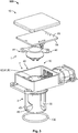
- FIGs. 2 , 3 and 4 the details of the fluid quality sensor 1 and a sensor assembly 10 comprising the fluid quality sensor 1 is shown.
- FIG. 2 a cross-sectional view of a fluid quality sensor 1 attached to the pump 5 is shown.
- Figs. 3 and 4 the sensor assembly 10 is shown without the pump 5.
- the pump 5 is only shown schematically in Fig. 2 .
- the pump 5 has an input side 8 where an input line 38 supplying the fluid 2 is attached. This side is the low pressure side 73.
- the pump 5 is a pressure pump 58.
- the pump 5, 58 creates a pressure for pumping the fluid 2 from the input side 8 to the output side 7 to which an output line 37 is attached.
- the pump comprises a fluid cavity 25 at the output side 7.
- the measurement section 3 of the fluid quality sensor 1 is configured to be mounted to the output side 7 of the pump 5. In the embodiment shown in Fig. 2 , the measurement section 3 is actually located at the output side 7. The measurement section 3 is at least partially located in a fluid cavity 8 of the pump 5. A measurement area 30, at which the quality of the fluid 2 is measured, is located in the fluid cavity 25 which in this case is a high pressure fluid cavity in which 4.5 to 8.5 bar are present.
- the fluid quality sensor 1 thus comprises an ultrasound source 40 and an ultrasound detector 41, which emit and absorb ultrasonic waves for measuring the quality.
- the fluid quality sensor 1 comprises a reflector structure 45 with a reflector surface 46 located at an inside of an end of the reflector structure 45.
- the reflector structure 45 is fixed to the fluid quality sensor 1, in particular, a housing 50 of the sensor assembly 10.
- the reflector surface 46 has a predefined distance from the ultrasound source 40 and the ultrasound detector 41.
- the fluid quality sensor 1 can thus be used in several different pumps without the need for an initial gauging measurement.
- the reflector structure 45 has the shape of a cage with several openings allowing sufficient stream of the fluid 2 through it.
- the sensor assembly 10 comprises further sensors, in particular a pressure sensor 12 and a temperature sensor 11 for measuring the pressure and the temperature at the output side 7 and in the fluid cavity 25.
- the sensor assembly 10 has a common housing 50 to achieve a compact design.
- the sensor assembly 10 is a common output 51 in the common supply 52 for all the sensors 1, 11, 12.
- the data or signals output by the sensor assembly 10 are supplied to the ECU 105 with the cable 101.
- the sensor assembly 10 further comprises electric parts 55 for controlling the sensor assembly 10, in particular the fluid quality sensor 1.
- the sensor assembly 10 also comprises electric parts 56 for analyzing or converting the measurement data.
- the fluid quality sensor 1 also comprises a disc-like transmission element 81 for transmitting the ultrasound waves.
- the transition element 80 also serves as a protection element 82 protecting the sensor assembly 10 from the harmful fluid 2 which could otherwise damage parts of the fluid quality sensor 1.
Landscapes
- Engineering & Computer Science (AREA)
- Chemical & Material Sciences (AREA)
- Combustion & Propulsion (AREA)
- Chemical Kinetics & Catalysis (AREA)
- General Engineering & Computer Science (AREA)
- Mechanical Engineering (AREA)
- Health & Medical Sciences (AREA)
- Toxicology (AREA)
- General Physics & Mathematics (AREA)
- Physics & Mathematics (AREA)
- Analytical Chemistry (AREA)
- Investigating Or Analyzing Materials By The Use Of Ultrasonic Waves (AREA)
- Exhaust Gas After Treatment (AREA)
- Measuring Fluid Pressure (AREA)
Priority Applications (3)
| Application Number | Priority Date | Filing Date | Title |
|---|---|---|---|
| EP17305723.3A EP3415733A1 (fr) | 2017-06-14 | 2017-06-14 | Capteur de qualité de fluide pour mesurer la qualité d'un fluide, ensemble capteur et ensemble pour moteurs à combustion interne comprenant un capteur de qualité de fluides |
| CN201810605780.0A CN109083723B (zh) | 2017-06-14 | 2018-06-13 | 流体质量传感器、传感器组件和用于燃烧式发动机的组件 |
| US16/008,690 US11112335B2 (en) | 2017-06-14 | 2018-06-14 | Fluid quality sensor for measuring the quality of a fluid, sensor assembly and assembly for combustion engines comprising a fluid quality sensor |
Applications Claiming Priority (1)
| Application Number | Priority Date | Filing Date | Title |
|---|---|---|---|
| EP17305723.3A EP3415733A1 (fr) | 2017-06-14 | 2017-06-14 | Capteur de qualité de fluide pour mesurer la qualité d'un fluide, ensemble capteur et ensemble pour moteurs à combustion interne comprenant un capteur de qualité de fluides |
Publications (1)
| Publication Number | Publication Date |
|---|---|
| EP3415733A1 true EP3415733A1 (fr) | 2018-12-19 |
Family
ID=59269971
Family Applications (1)
| Application Number | Title | Priority Date | Filing Date |
|---|---|---|---|
| EP17305723.3A Withdrawn EP3415733A1 (fr) | 2017-06-14 | 2017-06-14 | Capteur de qualité de fluide pour mesurer la qualité d'un fluide, ensemble capteur et ensemble pour moteurs à combustion interne comprenant un capteur de qualité de fluides |
Country Status (3)
| Country | Link |
|---|---|
| US (1) | US11112335B2 (fr) |
| EP (1) | EP3415733A1 (fr) |
| CN (1) | CN109083723B (fr) |
Citations (5)
| Publication number | Priority date | Publication date | Assignee | Title |
|---|---|---|---|---|
| US20110293450A1 (en) * | 2010-06-01 | 2011-12-01 | Micropump, Inc. | Pump magnet housing with integrated sensor element |
| EP2743471A1 (fr) * | 2012-12-17 | 2014-06-18 | Deere & Company | Système de distribution d'agent réducteur |
| WO2014118248A1 (fr) * | 2013-01-30 | 2014-08-07 | Inergy Automotive Systems Research (Société Anonyme) | Procédé de surveillance de la qualité de l'urée dans un système de rcs |
| WO2015018737A1 (fr) * | 2013-08-07 | 2015-02-12 | Emitec Gesellschaft Für Emissionstechnologie Mbh | Procédé de détermination de qualité d'agent réducteur |
| US9089799B2 (en) * | 2011-08-08 | 2015-07-28 | Ti Group Automotive Systems, L.L.C. | Fluid distribution system with filtration |
Family Cites Families (15)
| Publication number | Priority date | Publication date | Assignee | Title |
|---|---|---|---|---|
| US5039279A (en) * | 1990-03-15 | 1991-08-13 | Abbott Laboratories | Sensor for detecting fluid flow from a positive displacement pump |
| US6461323B2 (en) * | 2000-05-03 | 2002-10-08 | Reginald H. Fowler | Surgical system pump with flow sensor and method therefor |
| US6536271B1 (en) * | 2001-09-13 | 2003-03-25 | Flowserve Management Company | Pump with integral flow monitoring |
| BR0301969A (pt) * | 2003-05-22 | 2005-03-15 | Brasil Compressores Sa | Conjunto sensor, bomba de fluidos e refrigerador |
| US8366402B2 (en) * | 2005-12-20 | 2013-02-05 | Schlumberger Technology Corporation | System and method for determining onset of failure modes in a positive displacement pump |
| US20130000743A1 (en) * | 2011-06-29 | 2013-01-03 | Ti Group Automotive Systems, L.L.C. | Scr fluid distribution and circulation system |
| US9903200B2 (en) * | 2011-07-19 | 2018-02-27 | Baker Hughes, A Ge Company, Llc | Viscosity measurement in a fluid analyzer sampling tool |
| DE102011112326A1 (de) * | 2011-09-02 | 2013-03-07 | Emitec Gesellschaft Für Emissionstechnologie Mbh | Vorrichtung zur Bereitstellung von flüssigem Reduktionsmittel mit einem Partikelsieb |
| KR101427956B1 (ko) * | 2012-12-05 | 2014-08-08 | 현대자동차 주식회사 | 우레아 수용액 품질 판단 시스템 |
| WO2015038588A1 (fr) * | 2013-09-10 | 2015-03-19 | Covidien Lp | Pompe d'alimentation entérale comportant un capteur d'accélération |
| WO2015066310A1 (fr) * | 2013-10-30 | 2015-05-07 | Lime Instruments Llc | Ensemble capteur pour mesure de pression dynamique dans des pompes alternatives |
| GB2528601A (en) * | 2015-10-16 | 2016-01-27 | Gm Global Tech Operations Inc | A method of managing a selective catalytic reduction system of a motor vehicle |
| JP6508475B2 (ja) * | 2015-10-27 | 2019-05-08 | 株式会社デンソー | 診断装置 |
| JP6650366B2 (ja) * | 2016-07-27 | 2020-02-19 | 日本精機株式会社 | 圧力センサ装置、および電動ポンプ |
| EP3443993A1 (fr) * | 2017-08-17 | 2019-02-20 | Berlin Heart GmbH | Pompe pourvue de capteur de rotor permettant la détermination des paramètres physiologiques, des paramètres de débit et des paramètres de mouvement |
-
2017
- 2017-06-14 EP EP17305723.3A patent/EP3415733A1/fr not_active Withdrawn
-
2018
- 2018-06-13 CN CN201810605780.0A patent/CN109083723B/zh active Active
- 2018-06-14 US US16/008,690 patent/US11112335B2/en active Active
Patent Citations (5)
| Publication number | Priority date | Publication date | Assignee | Title |
|---|---|---|---|---|
| US20110293450A1 (en) * | 2010-06-01 | 2011-12-01 | Micropump, Inc. | Pump magnet housing with integrated sensor element |
| US9089799B2 (en) * | 2011-08-08 | 2015-07-28 | Ti Group Automotive Systems, L.L.C. | Fluid distribution system with filtration |
| EP2743471A1 (fr) * | 2012-12-17 | 2014-06-18 | Deere & Company | Système de distribution d'agent réducteur |
| WO2014118248A1 (fr) * | 2013-01-30 | 2014-08-07 | Inergy Automotive Systems Research (Société Anonyme) | Procédé de surveillance de la qualité de l'urée dans un système de rcs |
| WO2015018737A1 (fr) * | 2013-08-07 | 2015-02-12 | Emitec Gesellschaft Für Emissionstechnologie Mbh | Procédé de détermination de qualité d'agent réducteur |
Also Published As
| Publication number | Publication date |
|---|---|
| US20180364133A1 (en) | 2018-12-20 |
| CN109083723A (zh) | 2018-12-25 |
| CN109083723B (zh) | 2022-11-29 |
| US11112335B2 (en) | 2021-09-07 |
Similar Documents
| Publication | Publication Date | Title |
|---|---|---|
| EP3611499B1 (fr) | Structure de choc, structure d'élimination de bulles et dispositif de test de concentration de liquide ultrasonore | |
| US20050069468A1 (en) | Device for the dosing of a reducing agent | |
| US9556774B2 (en) | Conveying unit for a liquid additive for exhaust gas after-treatment, tank for storing liquid additive, motor vehicle having the conveying unit and method for determining a liquid additive quantity in a tank | |
| KR102230828B1 (ko) | 배기가스 처리 시스템의 저장 탱크의 탱크 내용물을 모니터링하는 방법 및 장치 | |
| JP5946465B2 (ja) | 排ガス後処理システムに還元剤を供給するための装置 | |
| EP3274568B1 (fr) | Tube d'aspiration, capteur d'urée ayant un tube d'aspiration et système de réduction catalytique sélective (rcs) ayant un capteur d'urée et un mécanisme d'aspiration et un tube d'aspiration | |
| US20140096512A1 (en) | Reducing agent tank having a sensor for determining a fill level and motor vehicle having the tank | |
| CN104583549A (zh) | 尿素水喷射装置 | |
| DE102017221261A1 (de) | Ultraschallsensor, Tankeinbaueinheit mit einem Ultraschallsensor | |
| US20200232840A1 (en) | Level Sensor Assembly | |
| US12460566B2 (en) | Dosing module for use in aftertreatment systems for internal combustion engines | |
| US9664092B2 (en) | Diagnosing system for reductant dosing system | |
| EP3415733A1 (fr) | Capteur de qualité de fluide pour mesurer la qualité d'un fluide, ensemble capteur et ensemble pour moteurs à combustion interne comprenant un capteur de qualité de fluides | |
| US9624810B2 (en) | Delivery unit for a liquid additive with a temperature sensor, method for checking the operating state of a delivery unit and motor vehicle having a delivery unit | |
| EP2664760A1 (fr) | Structure de dissipation de chaleur d'une valve d'injection | |
| CN106150617B (zh) | 尿素喷射组件 | |
| US10591386B2 (en) | Dew point activation method for exhuast gas sensors | |
| CN106194712A (zh) | 一种用于计量泵的安全阀 | |
| US20250369383A1 (en) | Doser assembly with sensor assembly | |
| JP2022070425A (ja) | 尿素水タンク | |
| US9523301B2 (en) | Reducing agent metering system with leak monitoring | |
| US9388726B2 (en) | Delivery unit for a liquid additive and motor vehicle having a delivery unit | |
| CN115112287A (zh) | 一种具有冻结保护的汽车用水压传感装置 | |
| KR20080102555A (ko) | 배기계 유동 측정장치 | |
| GB2602209A (en) | Dosing module for use in aftertreatment systems for internal combustion engines |
Legal Events
| Date | Code | Title | Description |
|---|---|---|---|
| PUAI | Public reference made under article 153(3) epc to a published international application that has entered the european phase |
Free format text: ORIGINAL CODE: 0009012 |
|
| STAA | Information on the status of an ep patent application or granted ep patent |
Free format text: STATUS: THE APPLICATION HAS BEEN PUBLISHED |
|
| AK | Designated contracting states |
Kind code of ref document: A1 Designated state(s): AL AT BE BG CH CY CZ DE DK EE ES FI FR GB GR HR HU IE IS IT LI LT LU LV MC MK MT NL NO PL PT RO RS SE SI SK SM TR |
|
| AX | Request for extension of the european patent |
Extension state: BA ME |
|
| STAA | Information on the status of an ep patent application or granted ep patent |
Free format text: STATUS: REQUEST FOR EXAMINATION WAS MADE |
|
| 17P | Request for examination filed |
Effective date: 20190617 |
|
| RBV | Designated contracting states (corrected) |
Designated state(s): AL AT BE BG CH CY CZ DE DK EE ES FI FR GB GR HR HU IE IS IT LI LT LU LV MC MK MT NL NO PL PT RO RS SE SI SK SM TR |
|
| RAP1 | Party data changed (applicant data changed or rights of an application transferred) |
Owner name: TE CONNECTIVITY NORGE AS Owner name: MEASUREMENT SPECIALTIES, INC. Owner name: MEAS FRANCE |
|
| STAA | Information on the status of an ep patent application or granted ep patent |
Free format text: STATUS: EXAMINATION IS IN PROGRESS |
|
| STAA | Information on the status of an ep patent application or granted ep patent |
Free format text: STATUS: THE APPLICATION HAS BEEN WITHDRAWN |
|
| 17Q | First examination report despatched |
Effective date: 20210625 |
|
| 18W | Application withdrawn |
Effective date: 20210722 |