EP3415768A1 - Ensemble ventilateur à rotor excentrique - Google Patents
Ensemble ventilateur à rotor excentrique Download PDFInfo
- Publication number
- EP3415768A1 EP3415768A1 EP17175765.1A EP17175765A EP3415768A1 EP 3415768 A1 EP3415768 A1 EP 3415768A1 EP 17175765 A EP17175765 A EP 17175765A EP 3415768 A1 EP3415768 A1 EP 3415768A1
- Authority
- EP
- European Patent Office
- Prior art keywords
- fan assembly
- rotor
- volute casing
- inlet opening
- volute
- Prior art date
- Legal status (The legal status is an assumption and is not a legal conclusion. Google has not performed a legal analysis and makes no representation as to the accuracy of the status listed.)
- Ceased
Links
- 230000007704 transition Effects 0.000 claims description 2
- 230000000052 comparative effect Effects 0.000 description 3
- 230000006835 compression Effects 0.000 description 3
- 238000007906 compression Methods 0.000 description 3
- 239000000463 material Substances 0.000 description 3
- PXHVJJICTQNCMI-UHFFFAOYSA-N Nickel Chemical compound [Ni] PXHVJJICTQNCMI-UHFFFAOYSA-N 0.000 description 2
- 229910052751 metal Inorganic materials 0.000 description 2
- 239000002184 metal Substances 0.000 description 2
- 238000012986 modification Methods 0.000 description 2
- 230000004048 modification Effects 0.000 description 2
- RYGMFSIKBFXOCR-UHFFFAOYSA-N Copper Chemical compound [Cu] RYGMFSIKBFXOCR-UHFFFAOYSA-N 0.000 description 1
- 229910000831 Steel Inorganic materials 0.000 description 1
- 229910001069 Ti alloy Inorganic materials 0.000 description 1
- RTAQQCXQSZGOHL-UHFFFAOYSA-N Titanium Chemical compound [Ti] RTAQQCXQSZGOHL-UHFFFAOYSA-N 0.000 description 1
- 238000004378 air conditioning Methods 0.000 description 1
- 229910045601 alloy Inorganic materials 0.000 description 1
- 239000000956 alloy Substances 0.000 description 1
- 229910052782 aluminium Inorganic materials 0.000 description 1
- XAGFODPZIPBFFR-UHFFFAOYSA-N aluminium Chemical compound [Al] XAGFODPZIPBFFR-UHFFFAOYSA-N 0.000 description 1
- 238000010276 construction Methods 0.000 description 1
- 238000001816 cooling Methods 0.000 description 1
- 229910052802 copper Inorganic materials 0.000 description 1
- 239000010949 copper Substances 0.000 description 1
- 230000008878 coupling Effects 0.000 description 1
- 238000010168 coupling process Methods 0.000 description 1
- 238000005859 coupling reaction Methods 0.000 description 1
- 238000010438 heat treatment Methods 0.000 description 1
- 230000002452 interceptive effect Effects 0.000 description 1
- 229910001092 metal group alloy Inorganic materials 0.000 description 1
- 239000000203 mixture Substances 0.000 description 1
- 229910052759 nickel Inorganic materials 0.000 description 1
- 239000007787 solid Substances 0.000 description 1
- 239000010959 steel Substances 0.000 description 1
- 239000010936 titanium Substances 0.000 description 1
- 229910052719 titanium Inorganic materials 0.000 description 1
Images


Classifications
-
- F—MECHANICAL ENGINEERING; LIGHTING; HEATING; WEAPONS; BLASTING
- F04—POSITIVE - DISPLACEMENT MACHINES FOR LIQUIDS; PUMPS FOR LIQUIDS OR ELASTIC FLUIDS
- F04D—NON-POSITIVE-DISPLACEMENT PUMPS
- F04D29/00—Details, component parts, or accessories
- F04D29/40—Casings; Connections of working fluid
- F04D29/42—Casings; Connections of working fluid for radial or helico-centrifugal pumps
- F04D29/4206—Casings; Connections of working fluid for radial or helico-centrifugal pumps especially adapted for elastic fluid pumps
- F04D29/422—Discharge tongues
-
- F—MECHANICAL ENGINEERING; LIGHTING; HEATING; WEAPONS; BLASTING
- F04—POSITIVE - DISPLACEMENT MACHINES FOR LIQUIDS; PUMPS FOR LIQUIDS OR ELASTIC FLUIDS
- F04D—NON-POSITIVE-DISPLACEMENT PUMPS
- F04D29/00—Details, component parts, or accessories
- F04D29/40—Casings; Connections of working fluid
- F04D29/42—Casings; Connections of working fluid for radial or helico-centrifugal pumps
- F04D29/4206—Casings; Connections of working fluid for radial or helico-centrifugal pumps especially adapted for elastic fluid pumps
- F04D29/4226—Fan casings
-
- F—MECHANICAL ENGINEERING; LIGHTING; HEATING; WEAPONS; BLASTING
- F04—POSITIVE - DISPLACEMENT MACHINES FOR LIQUIDS; PUMPS FOR LIQUIDS OR ELASTIC FLUIDS
- F04D—NON-POSITIVE-DISPLACEMENT PUMPS
- F04D29/00—Details, component parts, or accessories
- F04D29/66—Combating cavitation, whirls, noise, vibration or the like; Balancing
- F04D29/661—Combating cavitation, whirls, noise, vibration or the like; Balancing especially adapted for elastic fluid pumps
- F04D29/663—Sound attenuation
-
- F—MECHANICAL ENGINEERING; LIGHTING; HEATING; WEAPONS; BLASTING
- F04—POSITIVE - DISPLACEMENT MACHINES FOR LIQUIDS; PUMPS FOR LIQUIDS OR ELASTIC FLUIDS
- F04D—NON-POSITIVE-DISPLACEMENT PUMPS
- F04D29/00—Details, component parts, or accessories
- F04D29/26—Rotors specially for elastic fluids
- F04D29/28—Rotors specially for elastic fluids for centrifugal or helico-centrifugal pumps for radial-flow or helico-centrifugal pumps
- F04D29/281—Rotors specially for elastic fluids for centrifugal or helico-centrifugal pumps for radial-flow or helico-centrifugal pumps for fans or blowers
- F04D29/282—Rotors specially for elastic fluids for centrifugal or helico-centrifugal pumps for radial-flow or helico-centrifugal pumps for fans or blowers the leading edge of each vane being substantially parallel to the rotation axis
Definitions
- the invention generally relates to a fan assembly, and more particularly to a centrifugal fan assembly.
- a centrifugal fan assembly is widely used for cooling, ventilating, and air-conditioning in automobiles, household electrical appliances, office equipment and industrial equipment, etc.
- a centrifugal fan assembly includes: a volute casing including an outlet section defining an outlet channel; a rotor mounted in the volute casing and rotatable around a rotor axis; and a cover fixed to the volute casing and defining an inlet opening therein.
- a fan assembly which provides higher air pressure and higher air flow under the same noise level, or provides lower noise under the same air flow and air pressure.
- a fan assembly comprises: a volute casing with a volute tongue; a rotor mounted in the volute casing and rotatable around a rotor axis; and a cover fixed to the volute casing and defining an inlet opening therein.
- the rotor axis is closer to the volute tongue than an axis of the inlet opening.
- the fan assembly can provide higher air pressure and higher air flow under the same noise level, or provide lower noise under the same air flow and air pressure.
- the rotor axis is spaced from the axis of the inlet opening in a direction parallel to the outlet flow direction by a distance equal to 2.0%-5.0% of the diameter of the inlet opening. More preferably, the distance is equal to 2.5%-2.7% of the diameter of the inlet opening. Most preferably, the distance is equal to 2.6% of the diameter of the inlet opening.
- the volute casing includes an outlet section defining an outlet channel, and the volute casing further includes a spiral sidewall, extending spirally around the rotor, and a bottom wall opposite to the cover.
- the width of the outlet channel is larger than 50% of a diameter of the volute casing as measured between opposing parts of the spiral sidewall in the direction of the width of the outlet channel. More preferably, the width of the outlet channel is between 52% and 60% of such diameter of the volute casing. Most preferably, the width of the outlet channel is between 54% of such diameter of the volute casing.
- the fan assembly can provide higher air pressure and higher air flow under the same noise level, or provide lower noise under the same air flow and air pressure.
- the volute casing comprises a flange with a plurality of mounting holes outside of the spiral sidewall.
- the fan assembly can be easily mounted to the components to be provided with the air flow.
- the volute tongue may include a concave portion with a plurality of different curvatures.
- noises of different frequencies are counteracting each other at the concave portion by the plurality of different curvatures.
- a fan assembly 10 that includes a volute casing 1, a rotor 2, and a cover 3.
- the volute casing 1 can be of a variety of shapes, sizes, and materials.
- volute casing 1 can be made of plastic, metal, or a combination thereof.
- the volute casing 1 can be small to enclose a small rotor design, or can be larger to accommodate an industrial-sized rotor.
- the fan assembly 10 may be in a horizontal orientation facing upward or facing downward.
- the fan assembly can alternatively be positioned in a vertical orientation, a tilted orientation, and a wide variety of other orientations.
- the fan assembly 10 of Fig. 1 is shown in a horizontal orientation facing upward, however, the fan assembly 10 may be used in other orientations.
- the volute casing 1 includes an outlet section 11 defining an outlet channel 12.
- the volute casing 1 further includes a spiral sidewall 13, extending spirally around the rotor 2, and a bottom wall 14 opposite to the cover 3.
- the spiral sidewall 13 is shaped such that the air flow is optimally guided so as to reduce unnecessary resistance.
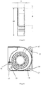
- the bottom wall 14 delimits a groove 15 for a cable 5 and a printed circuit board assembly 4, see Fig. 1 .
- a volute tongue 16 is located at a transition region between the outlet section 11 and the spiral sidewall 13.
- the volute tongue 16 is the region of the spiral sidewall 13 that bears the highest compression.
- the volute tongue 16 may include noise reduction features.
- the volute tongue 16 may include a concave portion with a plurality of different curvatures, so as to counteract noises of different frequencies at the concave portion by the plurality of different curvatures.
- the volute tongue 16 can utilize any other suitable shape to reduce the noise.
- the rotor axis 23 is closer to the volute tongue 16 than an axis 311 of the inlet opening 31.
- the rotor axis 23 is spaced from the axis 311 of the inlet opening 31 in a direction parallel to an outlet flow direction F by a distance d1 equal to 2.0%-5.0% of the diameter d2 of the inlet opening 31. More preferably, the distance d1 is equal to 2.5%-2.7% of the diameter d2 of the inlet opening 31. Most preferably, the distance d1 is equal to 2.6% of the diameter d2 of the inlet opening 31.
- the fan assembly 10 can provide higher air pressure and higher air flow under the same noise level, or provide lower noise under the same air flow and air pressure.
- the rotor 2 can be any type of rotor or impeller, including but not limited to a radial impeller and an axial impeller.
- the rotor can be a wide variety of sizes depending in part on the size of the volute casing and/or the intended use or location of the fan assembly.
- the rotor 2 is a radial impeller and includes at least one blade 22.
- the rotor 2 may include a hub 21 and a plurality of blades 22 disposed around and connected to the hub 21.
- each of the plurality of blades 22 is attached to the body of rotor 2 at the bottom of the blade 22 to form a basket-like impeller design.
- the impeller can be any of a variety of other shapes, with the blades 22 only attached at the top or bottom, or an alternating design.
- the blades 22 can be curved forward or curved backward, or can be a mixture of directions.
- the hub 21 is shaped as a dome, with the apex of the dome facing the direction of the incoming air.
- the hub 21 can have a solid construction, or can include spokes 24 as depicted in Fig. 6 in order to reduce the sound radiated from the bottom of the fan assembly 10.
- the rotor 2 has a maximum height 26 that is defined by the blades 22.
- the dome of the hub 21 has a maximum height 25 that can be equal to or less than the maximum height 26 of the rotor 2.
- the maximum height 25 of the dome of the hub 21 is between 1%-100% of the maximum height 26 of the rotor 2, and preferably in the range of 1% to 75%. According to another embodiment, the maximum height 25 of the dome of the hub 21 is 10% to 60% of the maximum height 26 of the rotor 2, and preferably in the range of 30% to 40%.
- the rotor 2 has an outer diameter 27 that is defined by the outermost tips of opposing blades 22.
- the rotor 2 also has an inner diameter 28 that is defined by the innermost tips of opposing blades 22.
- the outer diameter 29 of the hub 21 is between 1%-99% of such inner diameter 28, and preferably in the range of 20%-80%.
- Both the height and the diameter of the rotor 2 and the hub 21 can be designed or predetermined to maximize rotational speed and/or air flow, as well as to minimize noise, among many other design goals.
- the hub 21 of the rotor 2 co-rotates with the blades 22 of the rotor 2.
- air pulled into the rotor region will first encounter the hub 21 of the rotor 2 or the space just above the hub 21 of the rotor 2.
- the hub 21 with a dome shape causes the entering air to have a rotational component, which improves efficiency of the fan assembly 10.
- the rotor 2 may be manufactured from many metal alloys, including (but not limited to) steel, aluminum, nickel, copper, etc. It may be advantageous, according to an embodiment, to construct rotor 2 from an alloy of titanium, which may provide an optimal combination of weight to strength ratio, heat resistance, durability, etc. According to some embodiments, rotor 2 and/or blades 22 may be machined from AMS4928 titanium, or an alloy having substantially similar properties. According to other embodiments, rotor 2 and/or blades 22 may be heat treated to a particular hardness, such as, for example 30-50 HRC. It is contemplated that other materials and heat treatments may accomplish substantially similar structural and operational properties. Embodiments described herein are not intended to be limiting. As shown in Fig. 1 , the rotor 2 is mounted to the volute casing 1 by means of ball bearings 6. It is contemplated that the rotor 2 may be mounted to the volute casing 1 by means of any other suitable means.
- the cover 3 can be of corresponding shape and size to the volute casing 1.
- the cover 3 can be made of same or different materials from the volute casing 1.
- the cover 3 can be made of plastic, metal, or a combination thereof.
- the cover 3 defines an inlet opening 31 therein.
- the inlet opening 31 can be of a variety of shapes and sizes. In some embodiments, as depicted in Fig. 1 , the inlet opening 31 may be circular shaped in cross-section, but in any case defines an axis 311. It is contemplated that the inlet opening 31 may also have other shapes, such as oval.
- the inlet opening 31 can be tapered from the outside to the inside, so as to facilitate the introduction of the air.
- the hub 21 of the rotor 2 is fixed to a motor (not shown), and is driven by the motor.
- the motor may be any motor or drive sufficient to cause a desired rotation of the rotor 2.
- the motor includes a drive shaft that attaches to the hub 21 of the rotor 2 at a rotor axis 23 of the rotor 2.
- the motor can also be connected to the rotor 2 indirectly, such as through a coupling element.
- the motor can operate at a single rotational speed, or can operate at a variety of different speeds.
- the motor may also include operation profiles that provide predetermined variable speeds, or other variations.
- the motor can be positioned entirely on the side of the rotor facing away from the inlet opening 31, which prevents the motor from interfering with the air flow within the fan assembly.
- the motor may also be integrated with the printed circuit board assembly 4.
- the fan assembly 10 may optionally include a label 7.
- the label 7 may be of various forms and may be adhered to the hub 21 of the rotor 2.
- Fig. 4 is a schematic side view of an illustrative fan assembly according to an embodiment of the invention.
- the outlet channel 12 is shown to have a rectangular cross-section with height H and width W.
- the outlet channel 12 extends horizontally in the outlet flow direction F.
- the outlet channel 12 may also extend at an angle relative to the horizontal direction.
- the width W of the outlet channel 12 is larger than 50% of a diameter d3 of the volute casing 1 as measured between opposing parts of the spiral sidewall 13 in the direction of the width W of the outlet channel 12, preferably between 52% and 60% of such diameter d3, more preferably 54% of such diameter d3.
- Fig. 5 is a top view of an illustrative fan assembly 10 according to an embodiment of the invention.
- the volute casing 1 further comprises a flange 18 with a plurality of mounting holes 17 outside of the spiral sidewall 13.
- the flange 18 is also provided with a plurality of mounting holes 19, which align with corresponding mounting holes 32 of the cover 3, for fixing the cover 3 to the volute casing 1 by means of suitable fasteners (not shown).
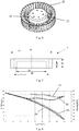
- Fig. 8 shows comparative performance curves of the fan assembly 10 according to an embodiment of the invention and a conventional fan assembly.
- the distance d1 that the rotor axis 23 is spaced from the axis 311 of the inlet opening 31 in a direction parallel to the outlet flow direction F direction is 1.85 mm
- the diameter d2 of the inlet opening 31 is 72 mm
- the ratio of the distance d1 to the diameter d2 of the inlet opening 31 is 2.6%.
- the width W of the outlet channel 12 is 74.39 mm
- the diameter d3 of the volute casing 1 as measured between opposing parts of the spiral sidewall 13 in the direction of the width W of the outlet channel 12 is 137.5 mm
- the ratio of the width W of the outlet channel 12 to the diameter d3 of the volute casing 1 is 54%.
- the rotor axis coincides with the axis of the inlet opening (that is, there is no distance between the rotor axis and the axis of the inlet opening), and the width of the outlet channel is 44.68 mm, thus, the ratio of the width of the outlet channel 12 to the diameter of the volute casing is 32%.
- performance curve C1 shows the noise level (in dBA) of the conventional fan assembly versus inlet air flow (in CFM)
- performance curve C2 shows the noise level (in dBA) of the fan assembly 10 according to the above embodiment versus inlet air flow (in CFM).
- performance curve C3 shows the air pressure (in mmAq) of the conventional fan assembly versus inlet air flow (in CFM)
- performance curve C4 shows the air pressure (in mmAq) of the fan assembly 10 according to the above embodiment versus inlet air flow (in CFM).
- the fan assembly 10 As can be seen by comparing the performance curves C1, C2, C3, and C4 , the fan assembly 10 according to the above embodiment produces about 3 dBA noise reduction under 30 CFM air flow, while producing an air pressure raised by 2 mmAq.
Landscapes
- Engineering & Computer Science (AREA)
- Mechanical Engineering (AREA)
- General Engineering & Computer Science (AREA)
- Structures Of Non-Positive Displacement Pumps (AREA)
Priority Applications (1)
| Application Number | Priority Date | Filing Date | Title |
|---|---|---|---|
| EP17175765.1A EP3415768A1 (fr) | 2017-06-13 | 2017-06-13 | Ensemble ventilateur à rotor excentrique |
Applications Claiming Priority (1)
| Application Number | Priority Date | Filing Date | Title |
|---|---|---|---|
| EP17175765.1A EP3415768A1 (fr) | 2017-06-13 | 2017-06-13 | Ensemble ventilateur à rotor excentrique |
Publications (1)
| Publication Number | Publication Date |
|---|---|
| EP3415768A1 true EP3415768A1 (fr) | 2018-12-19 |
Family
ID=59055110
Family Applications (1)
| Application Number | Title | Priority Date | Filing Date |
|---|---|---|---|
| EP17175765.1A Ceased EP3415768A1 (fr) | 2017-06-13 | 2017-06-13 | Ensemble ventilateur à rotor excentrique |
Country Status (1)
| Country | Link |
|---|---|
| EP (1) | EP3415768A1 (fr) |
Cited By (2)
| Publication number | Priority date | Publication date | Assignee | Title |
|---|---|---|---|---|
| CN112879324A (zh) * | 2019-11-29 | 2021-06-01 | 芜湖美的厨卫电器制造有限公司 | 风机组件和具有其的燃气热水器 |
| CN116498577A (zh) * | 2023-02-27 | 2023-07-28 | 宁波宝工电器有限公司 | 一种节能空调风轮组件 |
Citations (4)
| Publication number | Priority date | Publication date | Assignee | Title |
|---|---|---|---|---|
| US820399A (en) * | 1905-01-27 | 1906-05-15 | Samuel Cleland Davidson | Inlet-opening or eye of centrifugal fans or pumps. |
| DE3310376A1 (de) * | 1983-03-22 | 1984-09-27 | Ebm Elektrobau Mulfingen Gmbh & Co, 7119 Mulfingen | Radialgeblaese mit spiralgehaeuse |
| JPH05149297A (ja) * | 1991-11-28 | 1993-06-15 | Daikin Ind Ltd | 遠心フアン |
| US20050069410A1 (en) * | 2003-09-29 | 2005-03-31 | Denni Liao | Volute inlet of fan |
-
2017
- 2017-06-13 EP EP17175765.1A patent/EP3415768A1/fr not_active Ceased
Patent Citations (4)
| Publication number | Priority date | Publication date | Assignee | Title |
|---|---|---|---|---|
| US820399A (en) * | 1905-01-27 | 1906-05-15 | Samuel Cleland Davidson | Inlet-opening or eye of centrifugal fans or pumps. |
| DE3310376A1 (de) * | 1983-03-22 | 1984-09-27 | Ebm Elektrobau Mulfingen Gmbh & Co, 7119 Mulfingen | Radialgeblaese mit spiralgehaeuse |
| JPH05149297A (ja) * | 1991-11-28 | 1993-06-15 | Daikin Ind Ltd | 遠心フアン |
| US20050069410A1 (en) * | 2003-09-29 | 2005-03-31 | Denni Liao | Volute inlet of fan |
Cited By (2)
| Publication number | Priority date | Publication date | Assignee | Title |
|---|---|---|---|---|
| CN112879324A (zh) * | 2019-11-29 | 2021-06-01 | 芜湖美的厨卫电器制造有限公司 | 风机组件和具有其的燃气热水器 |
| CN116498577A (zh) * | 2023-02-27 | 2023-07-28 | 宁波宝工电器有限公司 | 一种节能空调风轮组件 |
Similar Documents
| Publication | Publication Date | Title |
|---|---|---|
| CA2517994C (fr) | Roue de soufflante radiale, unite de soufflante, et dispositif de soufflante radiale | |
| CN202545346U (zh) | 离心式鼓风机 | |
| US7125226B2 (en) | Impeller for radial-flow heat dissipating fan | |
| US7207779B2 (en) | Impeller for radial-flow heat dissipating fan | |
| EP1924772B1 (fr) | Ventilateur centrifuge d'appareil de traitement d'air | |
| JP5431748B2 (ja) | 電動モータ | |
| US20090136357A1 (en) | Bi-Directional Cooling Fan | |
| US11781591B2 (en) | Radial ventilator | |
| US20130230421A1 (en) | Centrifugal fan | |
| US20110031786A1 (en) | Centrifugal air blower and automobile seat | |
| EP2336573A2 (fr) | Ventilateur centrifuge profil bas haute efficacité | |
| KR20210114300A (ko) | 에어 서큘레이터 | |
| EP2488760B1 (fr) | Ventilateur axial et rotor de ventilateur | |
| US20240392807A1 (en) | Diagonal fan | |
| EP3415768A1 (fr) | Ensemble ventilateur à rotor excentrique | |
| US7607886B2 (en) | Heat-dissipating device | |
| KR100716207B1 (ko) | 다익송풍기 | |
| US11578731B2 (en) | Asymmetrical double-outlet blower | |
| JP2012013066A (ja) | 遠心式多翼ファン | |
| US7311494B2 (en) | Fan and scroll design for high efficiency and low noise | |
| KR102724274B1 (ko) | 쿨링팬 | |
| JPH0533797A (ja) | 押し込み式軸流フアン | |
| JPH0893684A (ja) | 遠心送風機 | |
| KR100669917B1 (ko) | 팬과 쉬라우드의 조립체 | |
| CN223578303U (zh) | 离心风机、空调及汽车 |
Legal Events
| Date | Code | Title | Description |
|---|---|---|---|
| PUAI | Public reference made under article 153(3) epc to a published international application that has entered the european phase |
Free format text: ORIGINAL CODE: 0009012 |
|
| AK | Designated contracting states |
Kind code of ref document: A1 Designated state(s): AL AT BE BG CH CY CZ DE DK EE ES FI FR GB GR HR HU IE IS IT LI LT LU LV MC MK MT NL NO PL PT RO RS SE SI SK SM TR |
|
| AX | Request for extension of the european patent |
Extension state: BA ME |
|
| RAP1 | Party data changed (applicant data changed or rights of an application transferred) |
Owner name: LUMILEDS HOLDING B.V. |
|
| STAA | Information on the status of an ep patent application or granted ep patent |
Free format text: STATUS: THE APPLICATION HAS BEEN REFUSED |
|
| 18R | Application refused |
Effective date: 20190121 |