EP3415920B1 - Dispositif d'analyse automatique - Google Patents
Dispositif d'analyse automatique Download PDFInfo
- Publication number
- EP3415920B1 EP3415920B1 EP17750010.5A EP17750010A EP3415920B1 EP 3415920 B1 EP3415920 B1 EP 3415920B1 EP 17750010 A EP17750010 A EP 17750010A EP 3415920 B1 EP3415920 B1 EP 3415920B1
- Authority
- EP
- European Patent Office
- Prior art keywords
- analysis
- sample
- reaction time
- items
- reaction vessel
- Prior art date
- Legal status (The legal status is an assumption and is not a legal conclusion. Google has not performed a legal analysis and makes no representation as to the accuracy of the status listed.)
- Active
Links
Images




Classifications
-
- G—PHYSICS
- G01—MEASURING; TESTING
- G01N—INVESTIGATING OR ANALYSING MATERIALS BY DETERMINING THEIR CHEMICAL OR PHYSICAL PROPERTIES
- G01N35/00—Automatic analysis not limited to methods or materials provided for in any single one of groups G01N1/00 - G01N33/00; Handling materials therefor
- G01N35/00584—Control arrangements for automatic analysers
- G01N35/0092—Scheduling
-
- G—PHYSICS
- G01—MEASURING; TESTING
- G01N—INVESTIGATING OR ANALYSING MATERIALS BY DETERMINING THEIR CHEMICAL OR PHYSICAL PROPERTIES
- G01N35/00—Automatic analysis not limited to methods or materials provided for in any single one of groups G01N1/00 - G01N33/00; Handling materials therefor
- G01N35/02—Automatic analysis not limited to methods or materials provided for in any single one of groups G01N1/00 - G01N33/00; Handling materials therefor using a plurality of sample containers moved by a conveyor system past one or more treatment or analysis stations
- G01N35/04—Details of the conveyor system
-
- G—PHYSICS
- G01—MEASURING; TESTING
- G01N—INVESTIGATING OR ANALYSING MATERIALS BY DETERMINING THEIR CHEMICAL OR PHYSICAL PROPERTIES
- G01N35/00—Automatic analysis not limited to methods or materials provided for in any single one of groups G01N1/00 - G01N33/00; Handling materials therefor
- G01N35/10—Devices for transferring samples or any liquids to, in, or from, the analysis apparatus, e.g. suction devices, injection devices
-
- G—PHYSICS
- G01—MEASURING; TESTING
- G01N—INVESTIGATING OR ANALYSING MATERIALS BY DETERMINING THEIR CHEMICAL OR PHYSICAL PROPERTIES
- G01N35/00—Automatic analysis not limited to methods or materials provided for in any single one of groups G01N1/00 - G01N33/00; Handling materials therefor
- G01N2035/00465—Separating and mixing arrangements
- G01N2035/00564—Handling or washing solid phase elements, e.g. beads
-
- G—PHYSICS
- G01—MEASURING; TESTING
- G01N—INVESTIGATING OR ANALYSING MATERIALS BY DETERMINING THEIR CHEMICAL OR PHYSICAL PROPERTIES
- G01N35/00—Automatic analysis not limited to methods or materials provided for in any single one of groups G01N1/00 - G01N33/00; Handling materials therefor
- G01N35/00584—Control arrangements for automatic analysers
- G01N2035/0097—Control arrangements for automatic analysers monitoring reactions as a function of time
-
- G—PHYSICS
- G01—MEASURING; TESTING
- G01N—INVESTIGATING OR ANALYSING MATERIALS BY DETERMINING THEIR CHEMICAL OR PHYSICAL PROPERTIES
- G01N35/00—Automatic analysis not limited to methods or materials provided for in any single one of groups G01N1/00 - G01N33/00; Handling materials therefor
- G01N35/02—Automatic analysis not limited to methods or materials provided for in any single one of groups G01N1/00 - G01N33/00; Handling materials therefor using a plurality of sample containers moved by a conveyor system past one or more treatment or analysis stations
- G01N35/04—Details of the conveyor system
- G01N2035/0439—Rotary sample carriers, i.e. carousels
- G01N2035/0441—Rotary sample carriers, i.e. carousels for samples
-
- G—PHYSICS
- G01—MEASURING; TESTING
- G01N—INVESTIGATING OR ANALYSING MATERIALS BY DETERMINING THEIR CHEMICAL OR PHYSICAL PROPERTIES
- G01N35/00—Automatic analysis not limited to methods or materials provided for in any single one of groups G01N1/00 - G01N33/00; Handling materials therefor
- G01N35/02—Automatic analysis not limited to methods or materials provided for in any single one of groups G01N1/00 - G01N33/00; Handling materials therefor using a plurality of sample containers moved by a conveyor system past one or more treatment or analysis stations
- G01N35/04—Details of the conveyor system
- G01N2035/0439—Rotary sample carriers, i.e. carousels
- G01N2035/0443—Rotary sample carriers, i.e. carousels for reagents
-
- G—PHYSICS
- G01—MEASURING; TESTING
- G01N—INVESTIGATING OR ANALYSING MATERIALS BY DETERMINING THEIR CHEMICAL OR PHYSICAL PROPERTIES
- G01N35/00—Automatic analysis not limited to methods or materials provided for in any single one of groups G01N1/00 - G01N33/00; Handling materials therefor
- G01N35/10—Devices for transferring samples or any liquids to, in, or from, the analysis apparatus, e.g. suction devices, injection devices
- G01N35/1065—Multiple transfer devices
- G01N2035/1076—Multiple transfer devices plurality or independently movable heads
-
- G—PHYSICS
- G01—MEASURING; TESTING
- G01N—INVESTIGATING OR ANALYSING MATERIALS BY DETERMINING THEIR CHEMICAL OR PHYSICAL PROPERTIES
- G01N35/00—Automatic analysis not limited to methods or materials provided for in any single one of groups G01N1/00 - G01N33/00; Handling materials therefor
- G01N35/10—Devices for transferring samples or any liquids to, in, or from, the analysis apparatus, e.g. suction devices, injection devices
- G01N35/1081—Devices for transferring samples or any liquids to, in, or from, the analysis apparatus, e.g. suction devices, injection devices characterised by the means for relatively moving the transfer device and the containers in an horizontal plane
- G01N35/1083—Devices for transferring samples or any liquids to, in, or from, the analysis apparatus, e.g. suction devices, injection devices characterised by the means for relatively moving the transfer device and the containers in an horizontal plane with one horizontal degree of freedom
- G01N2035/1086—Cylindrical, e.g. variable angle
-
- G—PHYSICS
- G01—MEASURING; TESTING
- G01N—INVESTIGATING OR ANALYSING MATERIALS BY DETERMINING THEIR CHEMICAL OR PHYSICAL PROPERTIES
- G01N33/00—Investigating or analysing materials by specific methods not covered by groups G01N1/00 - G01N31/00
- G01N33/48—Biological material, e.g. blood, urine; Haemocytometers
- G01N33/483—Physical analysis of biological material
- G01N33/487—Physical analysis of biological material of liquid biological material
- G01N33/49—Blood
- G01N33/4905—Determining clotting time of blood
-
- G—PHYSICS
- G01—MEASURING; TESTING
- G01N—INVESTIGATING OR ANALYSING MATERIALS BY DETERMINING THEIR CHEMICAL OR PHYSICAL PROPERTIES
- G01N35/00—Automatic analysis not limited to methods or materials provided for in any single one of groups G01N1/00 - G01N33/00; Handling materials therefor
- G01N35/02—Automatic analysis not limited to methods or materials provided for in any single one of groups G01N1/00 - G01N33/00; Handling materials therefor using a plurality of sample containers moved by a conveyor system past one or more treatment or analysis stations
- G01N35/025—Automatic analysis not limited to methods or materials provided for in any single one of groups G01N1/00 - G01N33/00; Handling materials therefor using a plurality of sample containers moved by a conveyor system past one or more treatment or analysis stations having a carousel or turntable for reaction cells or cuvettes
Definitions
- the present invention relates to an automatic analysis device for automatically analyzing components of blood or the like.
- an automatic analysis device that measures an amount of transmitted light or scattered light of a single or plural wavelengths obtained by irradiating a reaction solution which is a mixture of a sample and a reagent with light from a light source has been widely used.
- examples of such automatic analysis devices include a biochemical analysis device that quantitatively or qualitatively analyzes a target component in a biological sample and a blood clotting analysis device that measures coagulability of a sample blood, in the field of biochemical test, hematology test, and the like.
- reaction times are predetermined and thus measurements can be scheduled according to the reaction times.
- the reaction times are not fixed and therefore whether or not the blood clotting reaction is complete has to be judged at fixed intervals based on the measured amount of light. Accordingly, the actual measurement time to complete the reaction is sometimes shorter than the predicted reaction time depending on the state of the reagent or sample or the measurement conditions. Since the reaction completion time thus irregularly varies in blood clotting analyses, wasted time sometimes occurs in the time period required until the analyses of all the requested test items are complete, preventing the efficient analysis.
- PTL 1 For the purpose of reducing the analysis processing time of a sample for which plural items are analyzed, PTL 1 describes a technique in which when an instruction to measure plural analysis items is given for one sample, the items are allocated to reaction vessels sequentially from the item that requires the longest processing time. A similar technique is also disclosed in EP 1 672 370 A1 .
- the aforementioned aspect enables reduction of the time required until analyses of all test items requested for a plurality of specimens are complete, thereby realizing a more efficient and rapid analysis.
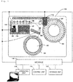
- Fig. 1 shows a basic configuration of the automatic analysis device according to the embodiment.
- the automatic analysis device an example of a device performing a blood clotting analysis will be described.
- an automatic analysis device 100 is mainly composed of sample vessels 101, a sample disk 102, reagent vessels 103, a reagent disk 104, a sample dispensing mechanism 105, a sample dispensing position 106, reaction vessels 107, reaction vessel placement units 108, a reaction vessel transporting mechanism 109, a reaction vessel stock unit 110, reaction ports 111, a reagent dispensing mechanism 112, a reagent dispensing mechanism washing mechanism 113, a reaction vessel disposing unit 114, an operating unit 115, a control unit 116, a storage unit 117, and an interface 118.
- the sample vessel 101 holds a sample or an accuracy control sample.
- the sample disk 102 holds a plurality of the sample vessels 101, and rotates in a clockwise or counterclockwise direction to transport a target one of the sample vessels 101 to a position where the sample dispensing mechanism 105 sucks the sample in the sample vessel 101.
- the reagent vessel 103 holds a reagent.
- the reagent disk 104 holds a plurality of the reagent vessels 103, and rotates in a clockwise or counterclockwise direction to transport a target one of the reagent vessels 103 to a position where the reagent dispensing mechanism 112 sucks the reagent in the reagent vessel 103.
- the sample dispensing mechanism 105 sucks the sample in the sample vessel 101 held in the sample disk 102 by an operation of a sample syringe (not shown) controlled by the control unit 116 and discharges the sample into the reaction vessel 107.
- the sample dispensing position 106 is a place for storing the sample in the reaction vessel 107.
- the reaction vessel 107 is transported to the sample dispensing position 106 by the reaction vessel transporting mechanism 109. After the transportation of the reaction vessel 107, the sample is discharged from the sample vessel 101 by the sample dispensing mechanism 105. After the discharge of the sample, the reaction vessel 107 holding the sample is transported to the reaction vessel placement unit 108 by the reaction vessel transporting mechanism 109.
- the reaction vessel 107 is a container for holding a mixed solution of the sample and the reagent dispensed.
- the reaction vessel transporting mechanism 109 transports the reaction vessel 107 that is empty held in the reaction vessel stock unit 110 to the reaction vessel placement unit 108, and transports the reaction vessel 107 whose analysis is complete from the reaction vessel placement unit 108 to the reaction vessel disposing unit 114.
- the reaction vessel stock unit 110 holds a plurality of the reaction vessels 107 that are unused.
- the reaction port 111 includes one or more (6 in the embodiment as one example) reaction vessel placement units 108 for placement of the reaction vessel 107 therein, and measures an optical intensity from a reaction solution contained in the reaction vessel 107 inserted in each of the reaction vessel placement units 108.
- each of the reaction vessel placement units 108 includes one light source (not shown) for emitting incident light to the reaction solution and one detection unit (optical sensor) for measuring the optical intensity inside the placement unit.
- the light source is placed on the bottom surface of the reaction vessel placement unit 108 and can emit light upward. The light scattered by the reaction solution is detected.
- the detection unit is placed on the side surface of the reaction vessel placement unit 108, and subjects the detected light to light/current conversion and outputs an optical measurement signal indicative of the optical intensity to an A/D converter.
- a measurement signal of the optical intensity A/D-converted in the A/D converter is sent via the interface 118 to the control unit 116 and to the storage unit 117.
- the arrangement of the light source and the detector is not necessarily limited to the above positional relation, and other arrangement may be adopted as long as the optical intensity from the reaction solution can be detected.
- the reagent dispensing mechanism 112 dispenses a reagent in the reagent vessel 103 held in the reagent disk 104 into the reaction vessel 107 placed in the reaction port 111 by an operation of a reagent syringe (not shown) controlled by the control unit 116.
- a reagent heating mechanism (not shown) controlled by the control unit 116 is built in the reagent dispensing mechanism 112 and heating a sucked reagent to an appropriate temperature (a prescribed temperature).
- the reagent dispensing mechanism washing mechanism 113 is a mechanism for washing the reagent dispensing mechanism 112 with water. The timing of the water washing is controlled by the control unit 116.
- the reaction vessel disposing unit 114 disposes the reaction vessel 107.
- the operating unit 115 is a computer that has an input terminal, such as a keyboard, a mouse, and an operation screen displayed on a display unit, as an input measure. Test items of samples to be analyzed are input from the keyboard or the operation screen provided in the operating unit 115 and then are input into the control unit 116.
- the control unit 116 controls the operations of the sample disk 102, the reagent disk 104, the sample dispensing mechanism 105, the reaction vessel transporting mechanism 109, the reaction port 111, the reagent dispensing mechanism 112, and the reagent dispensing mechanism washing mechanism 113 based on the input from the operating unit 115.
- the control unit 116 processes a measurement signal input from the detection unit via the interface 118 to calculate a blood clotting time or specify an abnormal part.
- the detail will be described later.
- the storage unit 117 stores, for example, input information from the operating unit 115, operation information of the sample disk 102 and the like, and information about reagents and samples.
- the interface 118 mediates between operation information of the sample disk 102 and the like and input information from the operating unit 115, and between operation information from the control unit 116 and information stored in the storage unit 117.
- the control unit 116 in Fig. 1 is connected to each constituent unit via the interface 118 to control the entire automatic analysis device, but an independent control unit may be provided for each constituent unit.
- An analysis of a sample is basically performed in the order of sample dispensing, reagent dispensing, optical measurement, disposing of the reaction vessel 107, and a data processing.
- a plurality of the reaction vessels 107 are arranged lengthwise and crosswise on the reaction vessel stock unit 110.
- the reaction vessel transporting mechanism 109 transports the reaction vessels 107 in the prescribed order from the reaction vessel stock unit 110 to the reaction vessel placement unit 108.
- sample disk 102 On the sample disk 102, a plurality of the sample vessels 101 are arranged in a row on the circumference, and the sample disk 102 rotates in the clockwise or counterclockwise direction according to the order of the samples to be analyzed to transport the sample vessels 101 to a position under the sample dispensing mechanism 105.
- the sample in the sample vessel 101 is sucked in a prescribed amount by the sample syringe (not shown) connected to the sample dispensing mechanism 105 and is dispensed into the reaction vessel 107.
- reagent disk 104 On the reagent disk 104, a plurality of the reagent vessels 103 are arranged in a row on the circumference, and when receiving instructions to select a test item and to start the analysis from the operating unit 115, the reagent disk 104 rotates in the clockwise or counterclockwise direction to transport the target reagent vessel 103 according to the test item to a position under the reagent dispensing mechanism 112.
- the reagent in the reagent vessel 103 is sucked in a prescribed amount by the reagent syringe (not shown) connected to the reagent dispensing mechanism 112 and is dispensed into the reaction vessel 107.
- a blood clotting reaction proceeds through mixing of the sample with the reagent.
- the mixed solution receives a luminous flux from the light source (not shown)
- the luminous flux is scattered by a solid produced by the blood clotting reaction in the mixed solution.
- the optical intensity scattered by the mixed solution is detected by the detection unit and is sensed by the reaction port 111.
- Analysis information such as the sensed optical intensity which is measurement data, the reaction port number used, the type of sample used, the placement position on the sample disk 102, the type of reagent used, and the placement position on the reagent disk 104, is stored in the storage unit 117.
- the control unit 116 determines at fixed intervals whether or not the blood clotting reaction is complete by using the sensed measurement data.
- the blood clotting time is calculated by the control unit 116, and the result file is stored in the storage unit 117 and is output to an output device, such as a display, included in the operating unit 115.
- the measurement is stopped at the time when the measurement time set by the operating unit 115 is reached.
- the blood clotting time is calculated by the control unit 116, and the result file is stored in the storage unit 117 and is output to an output device, such as a display, included in the operating unit 115.
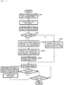
- Fig. 2 is a flow chart for explaining an operation control for determining the measurement order of test items according to the embodiment.
- the flow chart shown in Fig. 2 shows a flow of a processing in the automatic analysis device 100, in which a user inputs analysis parameters required for registration of test items into the automatic analysis device 100 via the operating unit 115 in advance, sets a sample and a reagent, and then starts analysis operations, and finally completion of the sample analyses is reached.
- the automatic analysis device 100 When receiving the instruction to start the analysis from the user, the automatic analysis device 100 reads out information (analysis items) imparted to each sample (step S201).
- information An example using a bar cord is described here.
- Information of items to be analyzed for a sample is contained in a bar cord attached to the sample and is read out by a bar cord reader (not shown).
- the control unit 116 sends the information (test items) read out by the bar cord reader to the operating unit 115.
- the operating unit 115 compares the test item information sent from the control unit 116 to information registered by the user, and sends information of the coincident test items (information required for performing the analysis operations, such as analysis parameters) to the control unit 116.
- the control unit 116 can thus read out analysis parameters of analysis items of samples to be tested.
- the predicted measurement times (hereinafter, sometimes simply referred to as predicted times) which are one of the analysis parameters read for each test item are read out and the test items are sorted in descending order of the predicted time length (step S202).
- the automatic analysis device 100 dispenses samples and reagents in the order sorted in step S202 and performs the analyses (step S203).
- the analyses are performed along the operations by the constituents of the automatic analysis device 100 described in Fig. 1 .
- each mechanism when a reaction of a sample being analyzed is complete in a shorter time than the predicted measurement time, each mechanism operates so as to use the reaction port for an analysis of the next sample without waiting until the predicted time is reached.
- Such an operation of each mechanism means, for example, that even when all the reaction ports 111 are used for analyses, the sample to be analyzed next is dispensed by the reagent dispensing mechanism 112 at the sample dispensing position 106 into an unused one of the reaction vessels 107 and is allowed to wait. Accordingly, as soon as the analysis of the sample in the reaction port 111 is complete, the reaction vessel 107 holding a sample for which the analysis is complete can be disposed to start transportation of the reaction vessel 107 for the next analysis to the reaction port 111 and analysis thereof. Thus, the reaction ports 111 can be efficiently used to perform continuous analyses.
- monitoring refers to regular communication of the automatic analysis device 100 with the operating unit 115.
- the operating unit 115 sends the content of the analysis request to the automatic analysis device 110 in the regular communication.
- step S205 When an extra analysis arises, the test item of the extra analysis is read out (step S205).
- step S206 the test item read in step S205 is combined with the test items which are read in step S201 and are sorted in step S202, and the combined test items are re-sorted in descending order of the measurement time length (step S206). Then, the process returns to step S203, and starts the analyses in the order re-sorted in step S206.
- step S207 determines whether or not the analyses of all the requested test items are complete is determined every time a measurement of a test item is complete. When all the requested items are not complete, the process returns to step S203, and the remaining items are analyzed in the sorted order. When it is determined that the analyses of all the requested items are complete in step S207, the analysis operation is ended.
- the measurement time sometimes varies relative to a measurement time predicted before the start of an analysis operation depending on the state of the samples and reagents as in a blood clotting analysis.
- wasted time occurs until a plurality of test items for all samples requested are complete, and the analysis efficiency may thus be lowered.
- wasted time occurs until the analyses of the test items are complete, wasted time also occurs in the time until the test operator receives the test results (turnaround time), affecting the final diagnosis time. Since there may be a highly urgent test item particularly in a blood clotting test, the wasted time in turnaround time is a very important problem.
- all test items requested before analysis operation are re-sorted in descending order of the measurement time length regardless of the difference in sample types. This enables sequential analyses from an item that requires a longer measurement time, and thus all requested analysis items of all specimens can be analyzed in the most efficient manner. Even if a blood clotting reaction of one sample is complete in a shorter time than the measurement time, occurrence of wasted time is prevented by analyzing next the test item requiring the longest measurement time among the remaining test items, and thus the analyses can be efficiently continued.
- each mechanism when a blood clotting reaction of a sample being analyzed is complete in a shorter time than the predicted reaction time, each mechanism operates so as to use the reaction port for the analysis of the next sample without waiting until the predicted time is elapsed.
- This results in reduction of time loss with no analysis operation the blood clotting analyses can be continuously performed, and the reaction vessels can be efficiently used, as compared with a configuration where operations for dispensing, measurement, and the like have to be performed at predetermined timings for a certain period of time even when any analysis is cancelled as in the case of a biochemical analysis automatic analysis device.
- the analyses of all the test items can be complete in a shorter time than in the case where the test items are re-sorted in descending order of the measurement time length for each sample. Accordingly, it is possible to increase the efficiency of the whole procedure until the tests of all requested test items are complete, and to rapidly provide the test results of the test items to a user.
- Fig. 3 is a schematic diagram for comparing relationships of measurement times between a measurement order in the case where the embodiment is applied and measurement orders determined by conventional techniques.
- Fig. 3 specifically shows an example where a blood clotting test with 10 items in total is performed according to an analysis item example shown in 301.
- 301(A) is a conventional example (1) and shows a measurement order in the case where measurements are performed in the order of request receipt.
- 301(B) is a conventional example (2) and shows a measurement order which is determined for each sample.
- 301(C) shows a measurement order which is determined beyond the difference in sample types according to the embodiment.
- 302 shows a criteria to indicate in-analytical operation of each sample and in-preparation for the operations.
- 303 is a timing chart in the measurement order determined by the conventional example (1) and shows the time until analyses are complete in the case of measurements in the order of request receipt.
- 304 is a timing chart in the measurement order determined by the conventional example (2) and shows the time until analyses are complete in the case of analyses in descending order of the reaction time length for each sample.
- 305 is a timing chart where the measurement order is determined according to the embodiment and shows the time until analyses are complete in the case where reaction times for all test items for a plurality of samples beyond the difference in sample types is taken into account.
- 303, 304 and 305 each represents usages of the 1st to 6th ports in the reaction ports 108.
- the time until the analyses are complete for all test items for all samples requested beyond the difference in sample types can be shortened in the analyses by the measurement order according to the embodiment as compared with the analyses by the measurement orders determined by the techniques of the conventional example (1) and the conventional example (2).
- Fig. 4 is a flow chart for explaining an operation control for determining the measurement order of test items in the automatic analysis device according to the embodiment (a second embodiment).
- a configuration including a reaction port where a specified test item is preferentially analyzed will be described.
- a mechanism for determining a priority port for a test item requiring a short measurement time will be described, but the embodiment is not limited to the example, and other conditions for specification can be adopted.
- step S401 the item to be measured in the priority port is specified (step S401). This is performed by a user via the operating unit 115 shown in Fig. 1 . A case where a test item requiring a measurement time of 1 minute is specified as the item to be measured in the priority port is described here, but what condition is adopted for the measurement in the priority port can be arbitrarily determined by a user.
- the measurement times of all items for all samples (which can be set here as 1 minute, 2 minutes, 3 minutes, 4 minutes, 5 minutes) are sorted in descending order, and then the presence or absence of any item for which a short measurement time (1 minute here) is set is checked (step S402).
- Reaction ports of the number corresponding to the thus obtained proportion are allocated as the reaction ports for preferentially analyzing the test items requiring a measurement time of 1 minute (step S404).
- the number of the reaction ports is 6 as described in Fig. 1
- test items for which the measurement time is set to 1 minute are preferentially analyzed as described above.
- the 6th port as a priority port may be used for another analysis.
- step S402 determines that there is no test item requiring a measurement time of 1 minute
- the reaction ports are allocated in descending order of the measurement time length (step S406) in the same manner as in Fig. 2 .
- all test items for all samples to be measured are re-sorted in descending order of the measurement time length and the analyses are performed.
- the analysis completion times of all test items can be shortened but when focused on the measurement time for each sample, the time until the analyses for one sample are complete may not be necessarily shortened. For example, when test items requiring measurement times of 1 minute and 5 minutes are requested for one sample, the item requiring a measurement time of 5 minutes is analyzed in an earlier stage under the mechanism for determining the analysis order and the test item requiring a measurement time of 1 minute is analyzed later among all the analysis items. Accordingly, when acquirement of analysis results is required for each sample, it may take a long time from start of the analyses to the acquirement.
- PT prothrombin time
- APTT activated partial thromboplastin time
- Fbg fibrinogen
- a priority port where items requiring a shorter measurement time are preferentially measured is provided.
- the embodiment includes a control mechanism in which the number of the priority ports is determined based on the proportion of the number of items requiring the shorter measurement time to the total number of test items. This leads to reduction of the time for acquisition of all the results of test items requiring different measurement times requested for the same sample, and thus the test results can be rapidly provided to a user.
- the embodiment illustrates an example where a priority port for items requiring a measurement time shorter than a prescribed time (1 minute) is provided.
- the embodiment covers examples where a priority port is provided for test items requiring a longer measurement time (for example, 4 minutes, 5 minutes, etc.).
- a priority port is provided for a specific test item under the same control mechanism.
- Fig. 5 is a schematic diagram for comparing relationships of measurement times between a measurement order in the case where the embodiment is applied and measurement orders determined by conventional techniques.
- the analysis item example 501 (501(A) to 501(C)) shown in Fig. 5 and a criteria 502 to indicate in-analytical operation of each sample and in-preparation for the operations are similar to 301 and 302 in Fig. 3 . That is, 501 (A) is a conventional example (1) and shows a measurement order in the case where measurements are performed in the order of request receipt. 501(B) is a conventional example (2) and shows a measurement order which is determined for each sample. 501(C) shows a measurement order which is determined beyond the difference in sample types according to the embodiment.
- 503 is a timing chart in the measurement order determined by the conventional example (1) and shows the time until analyses are complete in the case of the measurement in the order of request receipt.
- a measurement order 504 is a timing chart in the measurement order determined by the conventional example (2) and shows the time until analyses are complete in the case of analyses in descending order of the reaction time length for each sample.
- 505 is a timing chart in the case where the measurement order is determined according to the embodiment, and shows the time until analyses are complete in the case of using a priority port where items requiring a shorter measurement time are preferentially measured while taking into account the reaction times of all test items for a plurality of samples beyond the difference in sample types.
- 503, 504, and 505 each represents usages of the 1st to 6th ports in the reaction ports 108.
- the time until the analyses are complete required for all test items for all samples requested can be shortened in the case of analyses by the measurement order according to the embodiment as compared with the case of analyses by the order of request receipt or by the measurement order determined by a conventional technique.
Landscapes
- Chemical & Material Sciences (AREA)
- General Health & Medical Sciences (AREA)
- Life Sciences & Earth Sciences (AREA)
- Health & Medical Sciences (AREA)
- Analytical Chemistry (AREA)
- Biochemistry (AREA)
- Physics & Mathematics (AREA)
- General Physics & Mathematics (AREA)
- Immunology (AREA)
- Pathology (AREA)
- Chemical Kinetics & Catalysis (AREA)
- Automatic Analysis And Handling Materials Therefor (AREA)
- Investigating Or Analysing Biological Materials (AREA)
Claims (8)
- Dispositif d'analyse automatique comprenant :un récipient (101) pour échantillon pour contenir un échantillon ;un récipient (103) pour réactif pour contenir un réactif ;un mécanisme (105) de distribution d'échantillon pour distribuer l'échantillon depuis le récipient pour échantillon ;un mécanisme (112) de distribution de réactif pour distribuer le réactif depuis le récipient pour réactif ;un récipient (107) de réaction pour contenir une solution mixte de l'échantillon distribué depuis le mécanisme de distribution d'échantillon et du réactif distribué depuis le mécanisme de distribution de réactif ;une unité d'analyse qui inclut une pluralité d'unités (108) de mise en place de récipient de réaction pour une mise en place du récipient de réaction dans celle-ci, chacune de la pluralité d'unités de mise en place de récipient de réaction incluant une source de lumière pour émettre une lumière jusqu'au récipient de réaction contenant la solution mixte et une unité de réception de lumière pour recevoir la lumière émise depuis la source de lumière ;une unité opérationnelle (115) pour une entrée d'informations relatives à l'échantillon dans celle-ci ; etune unité (116) de commande pour commander l'unité d'analyse sur la base des informations entrées,dans lequel l'unité de commande est adaptée,lorsque des informations relatives à une pluralité d'échantillons sont entrées depuis l'unité opérationnelle, à comparer des longueurs de temps de réaction prédites d'items d'analyse requises pour la pluralité d'échantillons,lors de la détermination d'un ordre d'analyse de telle manière que des analyses des items d'analyse sont exécutées par ordre décroissant de la longueur de temps de réaction prédite, à calculer une proportion d'items d'analyse pour lesquels le temps de réaction prédit satisfait à une condition prédéterminée pour des items d'analyse sur la base du résultat de la comparaison des longueurs de temps de réaction prédites des items d'analyse requises pour la pluralité d'échantillons,à calculer le nombre des unités de mise en place de récipient de réaction où les items d'analyse pour lesquels le temps de réaction prédit satisfait à la condition prédéterminée sont préférentiellement analysés parmi la pluralité d'unités de mise en place de récipient de réaction dans l'unité d'analyse sur la base de la proportion calculée, etlors de la commande de l'unité d'analyse sur la base de l'ordre d'analyse déterminé, à commander l'unité d'analyse pour donner la priorité aux et ainsi préférentiellement analyser les items d'analyse pour lesquels le temps de réaction prédit satisfait à la condition prédéterminée dans le nombre calculé des unités de mise en place de récipient de réaction.
- Dispositif d'analyse automatique selon la revendication 1, dans lequel la condition prédéterminée est que le temps de réaction prédit pour un item d'analyse est plus court qu'un temps prédéterminé.
- Dispositif d'analyse automatique selon la revendication 1, dans lequel la condition prédéterminée est que le temps de réaction prédit pour un item d'analyse est plus long qu'un temps prédéterminé.
- Dispositif d'analyse automatique selon la revendication 1, dans lequel, lorsqu'une demande d'une analyse pour un échantillon supplémentaire survient dans les analyses, l'unité (116) de commande est adaptée à commander l'unité d'analyse pour préférentiellement analyser l'échantillon supplémentaire sans tenir compte de l'ordre d'analyse déterminé.
- Procédé d'analyse utilisant le dispositif d'analyse automatique selon la revendication 1, comprenant les étapes suivantes, mises en oeuvre par l'unité (116) de commande :lorsque des informations relatives à une pluralité d'échantillons sont entrées depuis l'unité opérationnelle (115), comparaison de longueurs de temps de réaction prédites d'items d'analyse requises pour la pluralité d'échantillons,lors de la détermination d'un ordre d'analyse de telle manière que des analyses des items d'analyse sont exécutées par ordre décroissant de la longueur de temps de réaction prédite, calcul (S403) d'une proportion d'items d'analyse pour lesquels le temps de réaction prédit satisfait à une condition prédéterminée pour des items d'analyse sur la base du résultat de la comparaison des longueurs de temps de réaction prédites des items d'analyse requises pour la pluralité d'échantillons,calcul (S404) du nombre des unités (108) de mise en place de récipient de réaction où les items d'analyse pour lesquels le temps de réaction prédit satisfait à la condition prédéterminée sont préférentiellement analysés parmi la pluralité d'unités de mise en place de récipient de réaction dans l'unité d'analyse sur la base de la proportion calculée, etlors de la commande de l'unité d'analyse sur la base de l'ordre d'analyse déterminé, commande de l'unité d'analyse pour donner la priorité aux et ainsi préférentiellement analyser les items d'analyse pour lesquels le temps de réaction prédit satisfait à la condition prédéterminée dans le nombre calculé des unités de mise en place de récipient de réaction.
- Procédé d'analyse selon la revendication 5, dans lequel la condition prédéterminée est que le temps de réaction prédit pour un item d'analyse est plus court qu'un temps prédéterminé.
- Procédé d'analyse selon la revendication 5, dans lequel la condition prédéterminée est que le temps de réaction prédit pour un item d'analyse est plus long qu'un temps prédéterminé.
- Procédé d'analyse selon la revendication 5, dans lequel, lorsqu'une demande d'une analyse pour un échantillon supplémentaire survient dans les analyses, l'unité (116) de commande commande l'unité d'analyse pour préférentiellement analyser l'échantillon supplémentaire sans tenir compte de l'ordre d'analyse déterminé.
Applications Claiming Priority (2)
| Application Number | Priority Date | Filing Date | Title |
|---|---|---|---|
| JP2016023232 | 2016-02-10 | ||
| PCT/JP2017/000702 WO2017138285A1 (fr) | 2016-02-10 | 2017-01-12 | Dispositif d'analyse automatique |
Publications (3)
| Publication Number | Publication Date |
|---|---|
| EP3415920A1 EP3415920A1 (fr) | 2018-12-19 |
| EP3415920A4 EP3415920A4 (fr) | 2019-10-23 |
| EP3415920B1 true EP3415920B1 (fr) | 2021-12-15 |
Family
ID=59563671
Family Applications (1)
| Application Number | Title | Priority Date | Filing Date |
|---|---|---|---|
| EP17750010.5A Active EP3415920B1 (fr) | 2016-02-10 | 2017-01-12 | Dispositif d'analyse automatique |
Country Status (5)
| Country | Link |
|---|---|
| US (1) | US11073526B2 (fr) |
| EP (1) | EP3415920B1 (fr) |
| JP (1) | JP6550152B2 (fr) |
| CN (1) | CN108700602B (fr) |
| WO (1) | WO2017138285A1 (fr) |
Families Citing this family (13)
| Publication number | Priority date | Publication date | Assignee | Title |
|---|---|---|---|---|
| WO2019087367A1 (fr) * | 2017-11-02 | 2019-05-09 | 株式会社島津製作所 | Méthode d'analyse, méthode de création de courbe d'étalonnage et analyseur de coagulation |
| EP3901632B1 (fr) * | 2018-12-19 | 2026-04-29 | Hitachi High-Tech Corporation | Dispositif d'analyse automatisé et procédé d'analyse |
| US20220326270A1 (en) * | 2019-06-26 | 2022-10-13 | Hitachi High-Tech Corporation | Automatic analysis device |
| JP7246498B2 (ja) * | 2019-09-04 | 2023-03-27 | 株式会社日立ハイテク | 複合型自動分析装置、システム、及び異常判定方法 |
| CN114521236B (zh) * | 2019-10-09 | 2026-02-24 | 株式会社日立高新技术 | 自动分析装置 |
| JP7326189B2 (ja) * | 2020-03-06 | 2023-08-15 | 株式会社日立ハイテク | 自動分析装置 |
| JP7395392B2 (ja) * | 2020-03-13 | 2023-12-11 | 株式会社日立ハイテク | 自動分析装置及び分析方法 |
| CN111273046B (zh) * | 2020-03-31 | 2024-12-24 | 桂林电子科技大学 | 一种基于机械臂夹取的多项目荧光定量检测装置 |
| JP7389719B2 (ja) * | 2020-07-09 | 2023-11-30 | 株式会社日立ハイテク | 開閉蓋装置およびそれを備えた自動分析装置 |
| CN114636829B (zh) * | 2020-12-15 | 2026-04-07 | 深圳市瑞图生物技术有限公司 | 样本检测任务执行方法、装置、计算机设备和存储介质 |
| CN113203870A (zh) * | 2021-03-28 | 2021-08-03 | 智锐达仪器科技南通有限公司 | 用于农药残留检测仪的检测方法及农药残留检测仪 |
| JP7810548B2 (ja) * | 2021-12-23 | 2026-02-03 | シスメックス株式会社 | 検体分析方法および検体分析装置 |
| CN118501484B (zh) * | 2024-07-18 | 2024-09-13 | 西安佰奥莱博生物科技有限公司 | 干式生化分析仪的时序控制方法、控制设备和存储介质 |
Family Cites Families (11)
| Publication number | Priority date | Publication date | Assignee | Title |
|---|---|---|---|---|
| JP2927082B2 (ja) * | 1990-11-28 | 1999-07-28 | 株式会社日立製作所 | 液体サンプル用分析方法および分析装置 |
| JPH09257804A (ja) * | 1996-03-27 | 1997-10-03 | Hitachi Ltd | 多項目自動分析方法およびその装置 |
| JP2001174468A (ja) * | 1999-12-15 | 2001-06-29 | Petroleum Energy Center | 自動試験システム |
| JP4448769B2 (ja) * | 2004-12-15 | 2010-04-14 | 株式会社日立ハイテクノロジーズ | 自動分析装置 |
| JP2010181197A (ja) * | 2009-02-03 | 2010-08-19 | Beckman Coulter Inc | 自動分析装置およびラック搬送方法 |
| JP2010217114A (ja) * | 2009-03-18 | 2010-09-30 | Beckman Coulter Inc | 自動分析装置、多ユニット自動分析装置、および予定分析終了時間算出方法 |
| US20120048036A1 (en) | 2009-04-09 | 2012-03-01 | Hitachi High-Technologies Corporation | Automatic analysis apparatus |
| JP5564037B2 (ja) * | 2009-04-09 | 2014-07-30 | 株式会社日立ハイテクノロジーズ | 自動分析装置 |
| JP5337727B2 (ja) * | 2010-01-28 | 2013-11-06 | 株式会社日立ハイテクノロジーズ | 自動分析装置 |
| JP5599219B2 (ja) * | 2010-04-20 | 2014-10-01 | 株式会社日立ハイテクノロジーズ | 自動分析装置及び自動分析方法 |
| JP2013122402A (ja) * | 2011-12-09 | 2013-06-20 | Canon Inc | 検体検査用分析装置 |
-
2017
- 2017-01-12 EP EP17750010.5A patent/EP3415920B1/fr active Active
- 2017-01-12 JP JP2017566550A patent/JP6550152B2/ja active Active
- 2017-01-12 US US16/072,956 patent/US11073526B2/en active Active
- 2017-01-12 WO PCT/JP2017/000702 patent/WO2017138285A1/fr not_active Ceased
- 2017-01-12 CN CN201780006443.3A patent/CN108700602B/zh active Active
Also Published As
| Publication number | Publication date |
|---|---|
| EP3415920A4 (fr) | 2019-10-23 |
| JP6550152B2 (ja) | 2019-07-31 |
| WO2017138285A1 (fr) | 2017-08-17 |
| US20190033332A1 (en) | 2019-01-31 |
| US11073526B2 (en) | 2021-07-27 |
| CN108700602B (zh) | 2021-08-10 |
| EP3415920A1 (fr) | 2018-12-19 |
| CN108700602A (zh) | 2018-10-23 |
| JPWO2017138285A1 (ja) | 2018-12-20 |
Similar Documents
| Publication | Publication Date | Title |
|---|---|---|
| EP3415920B1 (fr) | Dispositif d'analyse automatique | |
| JP7602524B2 (ja) | 自動分析装置及び自動分析方法 | |
| US10989708B2 (en) | Automated analysis device | |
| EP3349013B1 (fr) | Analyseur automatisé | |
| EP3086123B1 (fr) | Dispositif d'analyse automatique | |
| US11054433B2 (en) | Automated analyzer and control method for same | |
| JP2008209338A (ja) | 自動分析装置 | |
| US20170328925A1 (en) | Automatic analysis device | |
| JP2008039554A (ja) | 自動分析装置 | |
| WO2017047240A1 (fr) | Dispositif d'analyse automatisé | |
| JP6476003B2 (ja) | 自動分析システム | |
| JP5174629B2 (ja) | 自動分析装置 | |
| EP3901632B1 (fr) | Dispositif d'analyse automatisé et procédé d'analyse | |
| JP4383976B2 (ja) | 自動分析装置 | |
| JP2009294230A (ja) | 自動分析装置 |
Legal Events
| Date | Code | Title | Description |
|---|---|---|---|
| STAA | Information on the status of an ep patent application or granted ep patent |
Free format text: STATUS: THE INTERNATIONAL PUBLICATION HAS BEEN MADE |
|
| PUAI | Public reference made under article 153(3) epc to a published international application that has entered the european phase |
Free format text: ORIGINAL CODE: 0009012 |
|
| STAA | Information on the status of an ep patent application or granted ep patent |
Free format text: STATUS: REQUEST FOR EXAMINATION WAS MADE |
|
| 17P | Request for examination filed |
Effective date: 20180726 |
|
| AK | Designated contracting states |
Kind code of ref document: A1 Designated state(s): AL AT BE BG CH CY CZ DE DK EE ES FI FR GB GR HR HU IE IS IT LI LT LU LV MC MK MT NL NO PL PT RO RS SE SI SK SM TR |
|
| AX | Request for extension of the european patent |
Extension state: BA ME |
|
| DAV | Request for validation of the european patent (deleted) | ||
| DAX | Request for extension of the european patent (deleted) | ||
| A4 | Supplementary search report drawn up and despatched |
Effective date: 20190923 |
|
| RIC1 | Information provided on ipc code assigned before grant |
Ipc: G01N 33/49 20060101ALN20190917BHEP Ipc: G01N 35/00 20060101AFI20190917BHEP Ipc: G01N 35/02 20060101ALN20190917BHEP Ipc: G01N 33/86 20060101ALN20190917BHEP |
|
| RAP1 | Party data changed (applicant data changed or rights of an application transferred) |
Owner name: HITACHI HIGH-TECH CORPORATION |
|
| RIC1 | Information provided on ipc code assigned before grant |
Ipc: G01N 33/86 20060101ALN20210624BHEP Ipc: G01N 35/02 20060101ALN20210624BHEP Ipc: G01N 33/49 20060101ALN20210624BHEP Ipc: G01N 35/00 20060101AFI20210624BHEP |
|
| RIC1 | Information provided on ipc code assigned before grant |
Ipc: G01N 33/86 20060101ALN20210714BHEP Ipc: G01N 35/02 20060101ALN20210714BHEP Ipc: G01N 33/49 20060101ALN20210714BHEP Ipc: G01N 35/00 20060101AFI20210714BHEP |
|
| RIN1 | Information on inventor provided before grant (corrected) |
Inventor name: JOJI, AKIRA |
|
| RIC1 | Information provided on ipc code assigned before grant |
Ipc: G01N 33/86 20060101ALN20210809BHEP Ipc: G01N 35/02 20060101ALN20210809BHEP Ipc: G01N 33/49 20060101ALN20210809BHEP Ipc: G01N 35/00 20060101AFI20210809BHEP |
|
| GRAJ | Information related to disapproval of communication of intention to grant by the applicant or resumption of examination proceedings by the epo deleted |
Free format text: ORIGINAL CODE: EPIDOSDIGR1 |
|
| STAA | Information on the status of an ep patent application or granted ep patent |
Free format text: STATUS: GRANT OF PATENT IS INTENDED |
|
| GRAP | Despatch of communication of intention to grant a patent |
Free format text: ORIGINAL CODE: EPIDOSNIGR1 |
|
| INTG | Intention to grant announced |
Effective date: 20210924 |
|
| GRAS | Grant fee paid |
Free format text: ORIGINAL CODE: EPIDOSNIGR3 |
|
| GRAA | (expected) grant |
Free format text: ORIGINAL CODE: 0009210 |
|
| STAA | Information on the status of an ep patent application or granted ep patent |
Free format text: STATUS: THE PATENT HAS BEEN GRANTED |
|
| AK | Designated contracting states |
Kind code of ref document: B1 Designated state(s): AL AT BE BG CH CY CZ DE DK EE ES FI FR GB GR HR HU IE IS IT LI LT LU LV MC MK MT NL NO PL PT RO RS SE SI SK SM TR |
|
| REG | Reference to a national code |
Ref country code: GB Ref legal event code: FG4D Ref country code: CH Ref legal event code: EP |
|
| RIN1 | Information on inventor provided before grant (corrected) |
Inventor name: JOJI, AKIRA |
|
| REG | Reference to a national code |
Ref country code: IE Ref legal event code: FG4D Ref country code: DE Ref legal event code: R096 Ref document number: 602017050956 Country of ref document: DE |
|
| REG | Reference to a national code |
Ref country code: AT Ref legal event code: REF Ref document number: 1455877 Country of ref document: AT Kind code of ref document: T Effective date: 20220115 |
|
| REG | Reference to a national code |
Ref country code: LT Ref legal event code: MG9D |
|
| REG | Reference to a national code |
Ref country code: NL Ref legal event code: MP Effective date: 20211215 |
|
| PG25 | Lapsed in a contracting state [announced via postgrant information from national office to epo] |
Ref country code: RS Free format text: LAPSE BECAUSE OF FAILURE TO SUBMIT A TRANSLATION OF THE DESCRIPTION OR TO PAY THE FEE WITHIN THE PRESCRIBED TIME-LIMIT Effective date: 20211215 Ref country code: LT Free format text: LAPSE BECAUSE OF FAILURE TO SUBMIT A TRANSLATION OF THE DESCRIPTION OR TO PAY THE FEE WITHIN THE PRESCRIBED TIME-LIMIT Effective date: 20211215 Ref country code: FI Free format text: LAPSE BECAUSE OF FAILURE TO SUBMIT A TRANSLATION OF THE DESCRIPTION OR TO PAY THE FEE WITHIN THE PRESCRIBED TIME-LIMIT Effective date: 20211215 Ref country code: BG Free format text: LAPSE BECAUSE OF FAILURE TO SUBMIT A TRANSLATION OF THE DESCRIPTION OR TO PAY THE FEE WITHIN THE PRESCRIBED TIME-LIMIT Effective date: 20220315 |
|
| REG | Reference to a national code |
Ref country code: AT Ref legal event code: MK05 Ref document number: 1455877 Country of ref document: AT Kind code of ref document: T Effective date: 20211215 |
|
| PG25 | Lapsed in a contracting state [announced via postgrant information from national office to epo] |
Ref country code: SE Free format text: LAPSE BECAUSE OF FAILURE TO SUBMIT A TRANSLATION OF THE DESCRIPTION OR TO PAY THE FEE WITHIN THE PRESCRIBED TIME-LIMIT Effective date: 20211215 Ref country code: NO Free format text: LAPSE BECAUSE OF FAILURE TO SUBMIT A TRANSLATION OF THE DESCRIPTION OR TO PAY THE FEE WITHIN THE PRESCRIBED TIME-LIMIT Effective date: 20220315 Ref country code: LV Free format text: LAPSE BECAUSE OF FAILURE TO SUBMIT A TRANSLATION OF THE DESCRIPTION OR TO PAY THE FEE WITHIN THE PRESCRIBED TIME-LIMIT Effective date: 20211215 Ref country code: HR Free format text: LAPSE BECAUSE OF FAILURE TO SUBMIT A TRANSLATION OF THE DESCRIPTION OR TO PAY THE FEE WITHIN THE PRESCRIBED TIME-LIMIT Effective date: 20211215 Ref country code: GR Free format text: LAPSE BECAUSE OF FAILURE TO SUBMIT A TRANSLATION OF THE DESCRIPTION OR TO PAY THE FEE WITHIN THE PRESCRIBED TIME-LIMIT Effective date: 20220316 |
|
| PG25 | Lapsed in a contracting state [announced via postgrant information from national office to epo] |
Ref country code: NL Free format text: LAPSE BECAUSE OF FAILURE TO SUBMIT A TRANSLATION OF THE DESCRIPTION OR TO PAY THE FEE WITHIN THE PRESCRIBED TIME-LIMIT Effective date: 20211215 |
|
| PG25 | Lapsed in a contracting state [announced via postgrant information from national office to epo] |
Ref country code: SM Free format text: LAPSE BECAUSE OF FAILURE TO SUBMIT A TRANSLATION OF THE DESCRIPTION OR TO PAY THE FEE WITHIN THE PRESCRIBED TIME-LIMIT Effective date: 20211215 Ref country code: SK Free format text: LAPSE BECAUSE OF FAILURE TO SUBMIT A TRANSLATION OF THE DESCRIPTION OR TO PAY THE FEE WITHIN THE PRESCRIBED TIME-LIMIT Effective date: 20211215 Ref country code: RO Free format text: LAPSE BECAUSE OF FAILURE TO SUBMIT A TRANSLATION OF THE DESCRIPTION OR TO PAY THE FEE WITHIN THE PRESCRIBED TIME-LIMIT Effective date: 20211215 Ref country code: PT Free format text: LAPSE BECAUSE OF FAILURE TO SUBMIT A TRANSLATION OF THE DESCRIPTION OR TO PAY THE FEE WITHIN THE PRESCRIBED TIME-LIMIT Effective date: 20220418 Ref country code: ES Free format text: LAPSE BECAUSE OF FAILURE TO SUBMIT A TRANSLATION OF THE DESCRIPTION OR TO PAY THE FEE WITHIN THE PRESCRIBED TIME-LIMIT Effective date: 20211215 Ref country code: EE Free format text: LAPSE BECAUSE OF FAILURE TO SUBMIT A TRANSLATION OF THE DESCRIPTION OR TO PAY THE FEE WITHIN THE PRESCRIBED TIME-LIMIT Effective date: 20211215 Ref country code: CZ Free format text: LAPSE BECAUSE OF FAILURE TO SUBMIT A TRANSLATION OF THE DESCRIPTION OR TO PAY THE FEE WITHIN THE PRESCRIBED TIME-LIMIT Effective date: 20211215 |
|
| PG25 | Lapsed in a contracting state [announced via postgrant information from national office to epo] |
Ref country code: PL Free format text: LAPSE BECAUSE OF FAILURE TO SUBMIT A TRANSLATION OF THE DESCRIPTION OR TO PAY THE FEE WITHIN THE PRESCRIBED TIME-LIMIT Effective date: 20211215 Ref country code: AT Free format text: LAPSE BECAUSE OF FAILURE TO SUBMIT A TRANSLATION OF THE DESCRIPTION OR TO PAY THE FEE WITHIN THE PRESCRIBED TIME-LIMIT Effective date: 20211215 |
|
| REG | Reference to a national code |
Ref country code: CH Ref legal event code: PL |
|
| REG | Reference to a national code |
Ref country code: DE Ref legal event code: R097 Ref document number: 602017050956 Country of ref document: DE |
|
| PG25 | Lapsed in a contracting state [announced via postgrant information from national office to epo] |
Ref country code: MC Free format text: LAPSE BECAUSE OF FAILURE TO SUBMIT A TRANSLATION OF THE DESCRIPTION OR TO PAY THE FEE WITHIN THE PRESCRIBED TIME-LIMIT Effective date: 20211215 Ref country code: IS Free format text: LAPSE BECAUSE OF FAILURE TO SUBMIT A TRANSLATION OF THE DESCRIPTION OR TO PAY THE FEE WITHIN THE PRESCRIBED TIME-LIMIT Effective date: 20220415 |
|
| REG | Reference to a national code |
Ref country code: BE Ref legal event code: MM Effective date: 20220131 |
|
| PLBE | No opposition filed within time limit |
Free format text: ORIGINAL CODE: 0009261 |
|
| STAA | Information on the status of an ep patent application or granted ep patent |
Free format text: STATUS: NO OPPOSITION FILED WITHIN TIME LIMIT |
|
| PG25 | Lapsed in a contracting state [announced via postgrant information from national office to epo] |
Ref country code: LU Free format text: LAPSE BECAUSE OF NON-PAYMENT OF DUE FEES Effective date: 20220112 Ref country code: DK Free format text: LAPSE BECAUSE OF FAILURE TO SUBMIT A TRANSLATION OF THE DESCRIPTION OR TO PAY THE FEE WITHIN THE PRESCRIBED TIME-LIMIT Effective date: 20211215 Ref country code: AL Free format text: LAPSE BECAUSE OF FAILURE TO SUBMIT A TRANSLATION OF THE DESCRIPTION OR TO PAY THE FEE WITHIN THE PRESCRIBED TIME-LIMIT Effective date: 20211215 |
|
| 26N | No opposition filed |
Effective date: 20220916 |
|
| GBPC | Gb: european patent ceased through non-payment of renewal fee |
Effective date: 20220315 |
|
| PG25 | Lapsed in a contracting state [announced via postgrant information from national office to epo] |
Ref country code: SI Free format text: LAPSE BECAUSE OF FAILURE TO SUBMIT A TRANSLATION OF THE DESCRIPTION OR TO PAY THE FEE WITHIN THE PRESCRIBED TIME-LIMIT Effective date: 20211215 Ref country code: BE Free format text: LAPSE BECAUSE OF NON-PAYMENT OF DUE FEES Effective date: 20220131 |
|
| PG25 | Lapsed in a contracting state [announced via postgrant information from national office to epo] |
Ref country code: LI Free format text: LAPSE BECAUSE OF NON-PAYMENT OF DUE FEES Effective date: 20220131 Ref country code: CH Free format text: LAPSE BECAUSE OF NON-PAYMENT OF DUE FEES Effective date: 20220131 |
|
| PG25 | Lapsed in a contracting state [announced via postgrant information from national office to epo] |
Ref country code: IE Free format text: LAPSE BECAUSE OF NON-PAYMENT OF DUE FEES Effective date: 20220112 Ref country code: GB Free format text: LAPSE BECAUSE OF NON-PAYMENT OF DUE FEES Effective date: 20220315 |
|
| PG25 | Lapsed in a contracting state [announced via postgrant information from national office to epo] |
Ref country code: IT Free format text: LAPSE BECAUSE OF FAILURE TO SUBMIT A TRANSLATION OF THE DESCRIPTION OR TO PAY THE FEE WITHIN THE PRESCRIBED TIME-LIMIT Effective date: 20211215 |
|
| PG25 | Lapsed in a contracting state [announced via postgrant information from national office to epo] |
Ref country code: HU Free format text: LAPSE BECAUSE OF FAILURE TO SUBMIT A TRANSLATION OF THE DESCRIPTION OR TO PAY THE FEE WITHIN THE PRESCRIBED TIME-LIMIT; INVALID AB INITIO Effective date: 20170112 |
|
| PG25 | Lapsed in a contracting state [announced via postgrant information from national office to epo] |
Ref country code: MK Free format text: LAPSE BECAUSE OF FAILURE TO SUBMIT A TRANSLATION OF THE DESCRIPTION OR TO PAY THE FEE WITHIN THE PRESCRIBED TIME-LIMIT Effective date: 20211215 Ref country code: CY Free format text: LAPSE BECAUSE OF FAILURE TO SUBMIT A TRANSLATION OF THE DESCRIPTION OR TO PAY THE FEE WITHIN THE PRESCRIBED TIME-LIMIT Effective date: 20211215 |
|
| PG25 | Lapsed in a contracting state [announced via postgrant information from national office to epo] |
Ref country code: TR Free format text: LAPSE BECAUSE OF FAILURE TO SUBMIT A TRANSLATION OF THE DESCRIPTION OR TO PAY THE FEE WITHIN THE PRESCRIBED TIME-LIMIT Effective date: 20211215 |
|
| PG25 | Lapsed in a contracting state [announced via postgrant information from national office to epo] |
Ref country code: MT Free format text: LAPSE BECAUSE OF FAILURE TO SUBMIT A TRANSLATION OF THE DESCRIPTION OR TO PAY THE FEE WITHIN THE PRESCRIBED TIME-LIMIT Effective date: 20211215 |
|
| PGFP | Annual fee paid to national office [announced via postgrant information from national office to epo] |
Ref country code: FR Payment date: 20251217 Year of fee payment: 10 |
|
| PGFP | Annual fee paid to national office [announced via postgrant information from national office to epo] |
Ref country code: DE Payment date: 20251217 Year of fee payment: 10 |