EP3416014A1 - Procédé de synchronisation de données de processus entre des unités de commande redondantes - Google Patents
Procédé de synchronisation de données de processus entre des unités de commande redondantes Download PDFInfo
- Publication number
- EP3416014A1 EP3416014A1 EP18177426.6A EP18177426A EP3416014A1 EP 3416014 A1 EP3416014 A1 EP 3416014A1 EP 18177426 A EP18177426 A EP 18177426A EP 3416014 A1 EP3416014 A1 EP 3416014A1
- Authority
- EP
- European Patent Office
- Prior art keywords
- redundant
- module
- values
- output
- leg
- Prior art date
- Legal status (The legal status is an assumption and is not a legal conclusion. Google has not performed a legal analysis and makes no representation as to the accuracy of the status listed.)
- Granted
Links
Images






Classifications
-
- G—PHYSICS
- G05—CONTROLLING; REGULATING
- G05B—CONTROL OR REGULATING SYSTEMS IN GENERAL; FUNCTIONAL ELEMENTS OF SUCH SYSTEMS; MONITORING OR TESTING ARRANGEMENTS FOR SUCH SYSTEMS OR ELEMENTS
- G05B9/00—Safety arrangements
- G05B9/02—Safety arrangements electric
- G05B9/03—Safety arrangements electric with multiple-channel loop, i.e. redundant control systems
-
- G—PHYSICS
- G05—CONTROLLING; REGULATING
- G05B—CONTROL OR REGULATING SYSTEMS IN GENERAL; FUNCTIONAL ELEMENTS OF SUCH SYSTEMS; MONITORING OR TESTING ARRANGEMENTS FOR SUCH SYSTEMS OR ELEMENTS
- G05B19/00—Program-control systems
- G05B19/02—Program-control systems electric
- G05B19/04—Program control other than numerical control, i.e. in sequence controllers or logic controllers
- G05B19/05—Programmable logic controllers, e.g. simulating logic interconnections of signals according to ladder diagrams or function charts
- G05B19/052—Linking several PLC's
-
- G—PHYSICS
- G06—COMPUTING OR CALCULATING; COUNTING
- G06F—ELECTRIC DIGITAL DATA PROCESSING
- G06F11/00—Error detection; Error correction; Monitoring
- G06F11/07—Responding to the occurrence of a fault, e.g. fault tolerance
- G06F11/16—Error detection or correction of the data by redundancy in hardware
- G06F11/1658—Data re-synchronization of a redundant component, or initial sync of replacement, additional or spare unit
-
- G—PHYSICS
- G05—CONTROLLING; REGULATING
- G05B—CONTROL OR REGULATING SYSTEMS IN GENERAL; FUNCTIONAL ELEMENTS OF SUCH SYSTEMS; MONITORING OR TESTING ARRANGEMENTS FOR SUCH SYSTEMS OR ELEMENTS
- G05B2219/00—Program-control systems
- G05B2219/10—Plc systems
- G05B2219/14—Plc safety
- G05B2219/14014—Redundant processors and I-O
-
- G—PHYSICS
- G05—CONTROLLING; REGULATING
- G05B—CONTROL OR REGULATING SYSTEMS IN GENERAL; FUNCTIONAL ELEMENTS OF SUCH SYSTEMS; MONITORING OR TESTING ARRANGEMENTS FOR SUCH SYSTEMS OR ELEMENTS
- G05B2219/00—Program-control systems
- G05B2219/10—Plc systems
- G05B2219/14—Plc safety
- G05B2219/14113—Fault tolerant objectives for equipment, controller
-
- G—PHYSICS
- G05—CONTROLLING; REGULATING
- G05B—CONTROL OR REGULATING SYSTEMS IN GENERAL; FUNCTIONAL ELEMENTS OF SUCH SYSTEMS; MONITORING OR TESTING ARRANGEMENTS FOR SUCH SYSTEMS OR ELEMENTS
- G05B2219/00—Program-control systems
- G05B2219/20—Pc systems
- G05B2219/24—Pc safety
- G05B2219/24182—Redundancy
Definitions
- Disclosed embodiments relate to the synchronization of data received from input and output modules for redundant process controllers in process control systems.
- a fault-tolerant industrial process control system may employ a 1:1 redundancy system to synchronize the data in respective memories of a primary process controller and a secondary process controller. These memories are maintained in an identical fashion in both a primary memory associated with a primary process controller and a secondary memory associated with a redundant secondary process controller.
- the process controllers can comprise a Programmable Logic Controller (PLC) which includes various components that work together to bring information received from the field devices through input/output modules (IOs) that provide analog inputs (AIs) and digital inputs (DIs), evaluate that information along with other information including statuses, maintenance overrides, loop faults, channel faults and fault reaction, and then send control information back out to the IOs as analog outputs (AOs) and digital inputs (DOs) for controlling various controllable field devices such as actuators.
- PLC Programmable Logic Controller
- These basic PLC components comprise a power supply, central processing unit (CPU) or other processor (e.g., microcontroller) that is referred to herein generally as a 'process controller', co-processor or co-controller modules, and IOs that are generally separate from the process controller.
- CPU central processing unit
- microcontroller e.g., microcontroller
- IO channels which can be digital or analog. These IO channels can be non-redundant meaning each process controller is physically connected to a shared IO, or can be configured redundant meaning each process controller is connected to a dedicated IO which separately process the field values received from field devices such as sensors.
- the IO's processing of field value data received from sensors includes converting these measured analog data signals into logic signals referred to as "scan values" which can also be received as digital signals when the sensor includes an Analog-to-Digital (ADC) converter, that along with override flags and values written via the supervisory computers as well as output status values also from the IO are used as inputs for the process controller.
- ADC Analog-to-Digital
- AIs may be sensor values such as temperature or pressure in form of electrical current (general 4-20 ma) or electrical voltage (generally 1-5 V).
- DIs for example, may be valve open/close information or switch on/off status that have only 2 possible status, ON or OFF.
- AOs for example may be for driving a proportional valve
- DOs for example may be for driving open/close valves, lamps, horns or beacons.
- the scan values received by the process controllers that comprise AI, DI, as well as output status values also received from the IOs do not have to be equal for the respective process controllers that may be due to hardware and timing differences.
- each process controller needs to use time-synchronized scan values so that both of the redundant process controllers agree on the received scan values so that they agree on their calculated DO and AO values because otherwise the respective controller applications can take a different control path.
- the process controllers evaluate the scan values, and other variables such as output status, and override values and flags received from the supervisory computers, as it executes a stored computer program.
- the process controller then generates DO and AO as control signals, and sends these control signals to the IO(s) to update the status of these outputs.
- the process controllers connects to redundant IO modules so that there are two separate IO modules that each convert the control signals which can be DO and AO received from the process controller into digital or analog values that can be used to control field devices such as actuators.
- the calculated output values generated by the process controllers comprising DO and AO are also be synchronized as the redundant IO channels of the respective process controllers are tied together and the redundant IO channels must have the same output state/value.
- a plurality of statuses generally need to also be synchronized including maintenance overrides, loop faults, channel faults, and fault reaction.
- Disclosed process variable (PV) data synchronization and calculation between process controllers is implemented by process controllers that utilize only logic gates (e.g., AND, OR, or XOR gates) for performing the logical operations and calculations from the input scan data and output status values received from their 10, and override values and flags from the supervisory computer performed without any conditional branching.
- No conditional branching as used herein means for each data channel the logical operation is performed by the process controller independent of state or condition (e.g., a state or condition may be for example a software structure IF (condition is true) THEN do ELSE do), which is enabled by organizing the data in the processor's associated memory in a particular way that is described herein.
- memory organization refers the location and organization of the bits and bytes in the processor's memory which enables the above described data and status synchronization using only logic gates that are exclusive of any conditional branching for synchronizing the scan values, output status, override flags and override values, and calculating and synchronizing DO, and AO.
- the PV is the measured value of the process output, such as the temperature of a fluid exiting a tank, where the value of the PV is transmitted as a sensor signal from a sensor to the process controllers via the IOs which generates scan data comprising AI and DI, and output status.
- Disclosed data synchronization between process controllers makes the time for the process controllers to perform the calculations deterministic and always essentially the same so that they stay on the same control cycle.
- the disclosed data synchronization and calculation between process controller arrangement provides better performance, a deterministic throughput, and can be represented as electronic schematic format which enables implementation with discrete electronics or PLDs.
- Disclosed process data synchronization and calculation between redundant process controller embodiments can generally be applied to any method or system architecture where multiple input values are available and need to be synchronized between redundant processor controllers.
- Coupled to or “couples with” (and the like) as used herein without further qualification are intended to describe either an indirect or direct electrical connection.
- a first device “couples” to a second device, that connection can be through a direct electrical connection where there are only parasitics in the pathway, or through an indirect electrical connection via intervening items including other devices and connections.
- the intervening item generally does not modify the information of a signal but may adjust its current level, voltage level, and/or power level.
- FIG. 1 shows an example fault-tolerant industrial control system 100 comprising a redundant process controller 140 shown as comprising a first process controller (CP1) including a first CPU or first processor shown as processor 120 including a first associated memory 121, and a second redundant process controller (CP2) including a second CPU or processor shown as processor 130 including a second associated memory 131.
- the memories 121 and 131 generally comprise a battery backed-up random access memory (RAM), or some other non-volatile memory.
- the processors 120, 130 can comprise a microprocessor, digital signal processor (DSP), or a microcontroller unit (MCU).
- DSP digital signal processor
- MCU microcontroller unit
- a redundancy link 135 is for sharing data between CP1 and CP2.
- the redundancy link 135 does not perform any calculations.
- the distributed data shared between the CPs includes a plurality of channel configurations comprising DO, DI, AI and AO.
- FIGs. 5A-5D described below shows example all logic gate implementations for process controller synchronization of AI and DI and calculation of synchronized AO and DO, that can be used by CP1 and CP2 to ensure process controller synchronization for redundant process controllers.
- a redundant IO module 160 comprises a first IO module (IOM) 150 and a second IOM 155 that are between the process controller 140 and field devices comprising sensors 112 and actuators 113 which are coupled to processing equipment 114.
- the first IOM 150 and a second IOM 155 are shown receiving a channel (ch) shown as ch17 input from the sensors 112 and transmitting a ch shown as a ch2 output (AO or DO received from their CP) to the sensors 112 and to the actuators 113.
- the link 170 shown between the first IOM 150 and a second IOM 155 is the redundancy link between these redundant IOM.
- the IOMs 150 and 155 generate what is termed 'scan values' (AI and DI) and output status values from the data received from the field devices 112, 113 which is used by the process controller during 'scan times'.
- a first connection leg (shown as LegA) is shown connecting CP1 to the first IOM 150, and a second connection leg (shown as LegB) is shown connecting CP2 to the second IOM 155.
- CP1 receives scan values and output status values from first IOM 150 over LegA
- CP2 receives the scan values output status values from second IOM 155 over LegB.
- the legs can be wireless, or wired legs such as utilizing Ethernet.
- conditional branching is an IF (condition is true) THEN do ELSE do, so that for each channel the logical operation and calculation is performed by the process controllers CP1 and CP2 independent of state or condition (states such as used with IF (condition is true) THEN do ELSE do.
- DI data is stored in the other process controller's memory 121 or 131 which is enabled by disclosed memory organization.
- CP1 and CP2 takes care of gathering all the property information (properties comprising scan values, output status values, override flags and override values) and putting it into memory before sending it over the redundancy link 135 as one block or multiple blocks of data.
- FIGs. 2A and 2B collectively depicts two example methods of performing memory organization that can be utilized by disclosed process controllers.
- the properties in FIG. 2A and 2B shown are scan values (AI and DI), output status, override flags, and override values.
- the "organized per property" shown in FIG. 2A is suited for the logic calculations shown as arrows pointing down with channel properties per column of memory.
- the "organized per point" method shown in FIG. 2B has the channel properties kept together in row blocks of memory. Either of these two example methods of performing memory organization may be used with disclosed embodiments.
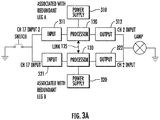
- FIG. 3A depicts example system components associated with redundant leg A and leg B shown in FIG. 1 in a redundant IO module arrangement that are linked through their respective process controllers by the redundancy link 135.
- Processor 120 is powered by power supply 310, while processor 130 is powered by power supply 320.
- the IOM associated with LegA comprises input 311 and output 312.
- the IOM associated with LegB comprises input 321 and output 322.
- processor 120 receives scanned data values and output status values from the input 311 of its IOM over LegA and processor 120 receives the scanned values output status values from the input 321 of its IOM over LegB.
- Disclosed processors as well their associated IOs can all be combined in the same process controller module as shown in FIG. 1 and FIG. 3A , or the processors can be in one module and their inputs and outputs can be stored in separate process controller modules. Redundant IO as shown in FIG. 3A has the 'redundant channel' value as used with FIGs. 5A , 5B , 5C , 5D set to logical '1' (high).
- FIG. 3B depicts example system components associated with non-redundant IO shown as input 311' and output 312' connected to both of the redundant leg A and leg B associated with the process controllers shown in FIG. 1 that are linked by redundancy link 135.
- Leg A is associated with processor 120 and Legb with processor 130.
- Non-redundant IO has the 'redundant channel' value as used with FIG 5A , 5B , 5C , 5D set to logical '0' (low).
- FIG. 4 depicts a redundant process controller 140 along with a redundant IO module 160 comprising IOMs 150 and 155.
- the IOMs 150 and 155 are each shown having modules at Node 1, with IOM 1.1 for IOM 150 and IOM 1.2 for IOM 155 at Node 1, and at Node 2 with IOM 2.1 for IOM 150 and IOM 2.2 for IOM 155.
- the IOMs 150 including IOM 1.1 and IOM 2.1 are connected by Leg A to CP1, and IOMs 155 including IOM 1.2 and IOM 2.2 are connected by Leg B to CP2.
- the redundant process controller 140 performs some checks on the property data including scan data values (AI and DI) and output status values received from the IOMs 150, 155, and also performs logic calculations on the property data received to generate synchronized AI and DI, and calculates synchronized output control values AO and DO.
- Disclosed PV synchronization and calculation as described above provides synchronization, checking and the necessary fault reaction that the redundant process controller 140 performs.
- the input values and output values are scanned and controlled by the IOMs 150 and 155.
- the IO modules 150, 155 periodically provide the scan values and output status values to the redundant process controller 140 and the redundant process controller 140 sends the synchronized output values (AO and DO) to the IOMs 150, 155.
- CP1 receives the property data including scan values and output status values from the IO modules 1.1 and 2.1 over LegA.
- CP2 receives the property data including scan values and output status values from IO module 1.2 and 2.2 over LegB.
- CP1 and CP2 exchange all the data comprising scan values (AI and DI), output status values, and override values, and override flags over the redundancy link 135 so that both CP1 and CP2 have the values from both Leg A and Leg B.
- CP1 and CP2 will each perform synchronization and calculations with an all logic implementation, and CP1 and CP2 will each generate output values AO and DO.
- CP1 and CP2 will receive the same input values (scan values, output status, override flags and override values) at essentially the same time (to be in the same control cycle) and calculate and then transmit the same output values AO and DO.
- Disclosed embodiments are further illustrated by the following specific Examples, which should not be construed as limiting the scope or content of this Disclosure in any way.
- the input channel being redundant or non-redundant is handled by disclosed logic by setting to logical '1' when the channel is redundant, and by setting to logical '0' when the channel is non-redundant.
- Output status values disclosed above are shown in FIGs. 5A-D as "actual output values".
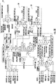
- FIG. 5A shows an example all logic implementation exclusive of any conditional branching for process controller DO PV calculations that provides DO synchronization for redundant process controllers.
- the store function box 540 shown is provided to avoid overwriting the values of the 'other' data types. For example, to prevent that the result of the DO-sync in FIG. 5A overwriting memory locations assigned to DI in FIG 5B .
- the store function box 540 can thus enable mixing data types.
- Labels 23, 24, 25, 26 Application value with On-line modification (OLM) applied.
- OLM On-Line Modification
- both CP1 and CP2 always execute the On-Line Modification (OLM) which allows one to change one or more channels from for example DI to AI or to add a new channel without losing the values from the previously configured channels. This allows no-break process control) simultaneously.
- the OLM flags are synchronized before use.
- Label 26 is the input which is stored as store actual output value LegX 525.
- FIG. 5B shows an example all logic implementation exclusive of any conditional branching for process controller DI synchronization for redundant process controllers, according to an example embodiment. With every significant logical output there is a number shown in FIG. 5B which is explained in detail below:
- FIG. 5C shows an example all logic implementation exclusive of any conditional branching for process controller AI calculations for redundant process controllers that provides that provides AI synchronization, according to an example embodiment. With every important logical output there is a number shown in FIG. 5C which is explained in detail below:
- FIG. 5D shows an example all logic implementation exclusive of any conditional branching for process controller AO PV calculations that provides AO synchronization for redundant process controllers, according to an example embodiment. With every important logical output there is a number shown in FIG. 5D which is explained in detail below:
Landscapes
- Engineering & Computer Science (AREA)
- Physics & Mathematics (AREA)
- General Physics & Mathematics (AREA)
- Theoretical Computer Science (AREA)
- Automation & Control Theory (AREA)
- Quality & Reliability (AREA)
- General Engineering & Computer Science (AREA)
- Hardware Redundancy (AREA)
Applications Claiming Priority (2)
| Application Number | Priority Date | Filing Date | Title |
|---|---|---|---|
| US201762520912P | 2017-06-16 | 2017-06-16 | |
| US16/003,588 US20180364673A1 (en) | 2017-06-16 | 2018-06-08 | Process data synchronization between redundant process controllers |
Publications (2)
| Publication Number | Publication Date |
|---|---|
| EP3416014A1 true EP3416014A1 (fr) | 2018-12-19 |
| EP3416014B1 EP3416014B1 (fr) | 2020-02-26 |
Family
ID=62630966
Family Applications (1)
| Application Number | Title | Priority Date | Filing Date |
|---|---|---|---|
| EP18177426.6A Active EP3416014B1 (fr) | 2017-06-16 | 2018-06-12 | Procédé de synchronisation de données de processus entre des unités de commande redondantes |
Country Status (2)
| Country | Link |
|---|---|
| US (1) | US20180364673A1 (fr) |
| EP (1) | EP3416014B1 (fr) |
Cited By (5)
| Publication number | Priority date | Publication date | Assignee | Title |
|---|---|---|---|---|
| CN110262367A (zh) * | 2019-08-05 | 2019-09-20 | 刘盛荣 | 智能家居设备控制方法及装置 |
| EP4102365A1 (fr) * | 2021-06-11 | 2022-12-14 | Honeywell International Inc. | Coordination d'un programme unique exécuté sur de multiples contrôleurs hôtes |
| CN115576187A (zh) * | 2022-11-23 | 2023-01-06 | 浙江中控研究院有限公司 | 一种多重冗余设计plc控制系统及系统控制方法 |
| CN116774666A (zh) * | 2022-03-10 | 2023-09-19 | 中国科学院沈阳自动化研究所 | 一种高安全完整性测控设备io诊断方法及装置 |
| CN118337112A (zh) * | 2024-06-13 | 2024-07-12 | 深圳小象电动科技有限公司 | 一种多轴向磁通电机串联安全冗余控制系统 |
Families Citing this family (11)
| Publication number | Priority date | Publication date | Assignee | Title |
|---|---|---|---|---|
| WO2020061388A1 (fr) * | 2018-09-20 | 2020-03-26 | Siemens Mobility GmbH | Appareil de capture de données à applications de sécurité et communication unidirectionnelle intégrées |
| US11481282B2 (en) * | 2019-03-29 | 2022-10-25 | Honeywell International Inc. | Redundant controllers or input-output gateways without dedicated hardware |
| US11762742B2 (en) | 2020-03-31 | 2023-09-19 | Honeywell International Inc. | Process control system with different hardware architecture controller backup |
| US11294843B2 (en) * | 2020-03-31 | 2022-04-05 | Honeywell International Inc. | On-process migration of controller(s) to utilize an IO pool |
| US11989084B2 (en) | 2020-09-23 | 2024-05-21 | Honeywell International Inc. | Self-healing process control system |
| US11874938B2 (en) | 2020-11-03 | 2024-01-16 | Honeywell International Inc. | Admittance mechanism |
| CN112269313B (zh) * | 2020-11-09 | 2022-12-09 | 西安热工研究院有限公司 | 一种io模块鉴别控制器双主的方法 |
| EP4063974B1 (fr) | 2021-03-23 | 2025-10-22 | ABB Schweiz AG | Commande d'un processus industriel à l'aide d'instances virtualisées de logiciels de contrôle |
| DE102021210600A1 (de) * | 2021-09-23 | 2023-03-23 | Robert Bosch Gesellschaft mit beschränkter Haftung | System zum Bereitstellen eines Ausgangssignals basierend auf einem generierten Umfeldmodell eines Umfelds einer mobilen Plattform |
| CN115913906A (zh) * | 2022-11-15 | 2023-04-04 | 中船航海科技有限责任公司 | 一种船用冗余控制系统及方法 |
| CN116699964B (zh) * | 2023-06-08 | 2025-07-22 | 南京南瑞继保电气有限公司 | 一种工业过程控制器冗余运行方法和系统 |
Citations (4)
| Publication number | Priority date | Publication date | Assignee | Title |
|---|---|---|---|---|
| US4672529A (en) * | 1984-10-26 | 1987-06-09 | Autech Partners Ltd. | Self contained data acquisition apparatus and system |
| EP0416891A2 (fr) * | 1989-09-05 | 1991-03-13 | Honeywell Inc. | Appareil pour fournir une interface universelle à un système de contrôle d'un procédé |
| US20070033435A1 (en) * | 2005-08-05 | 2007-02-08 | Honeywell International Inc. | Method and sytem for redundancy management of distributed and recoverable digital control system |
| US20150378337A1 (en) * | 2013-02-18 | 2015-12-31 | Endress+Hauser Gmbh+Co. Kg | Field device for a safety-critical application with redundant measuring channels in an fpga |
-
2018
- 2018-06-08 US US16/003,588 patent/US20180364673A1/en not_active Abandoned
- 2018-06-12 EP EP18177426.6A patent/EP3416014B1/fr active Active
Patent Citations (4)
| Publication number | Priority date | Publication date | Assignee | Title |
|---|---|---|---|---|
| US4672529A (en) * | 1984-10-26 | 1987-06-09 | Autech Partners Ltd. | Self contained data acquisition apparatus and system |
| EP0416891A2 (fr) * | 1989-09-05 | 1991-03-13 | Honeywell Inc. | Appareil pour fournir une interface universelle à un système de contrôle d'un procédé |
| US20070033435A1 (en) * | 2005-08-05 | 2007-02-08 | Honeywell International Inc. | Method and sytem for redundancy management of distributed and recoverable digital control system |
| US20150378337A1 (en) * | 2013-02-18 | 2015-12-31 | Endress+Hauser Gmbh+Co. Kg | Field device for a safety-critical application with redundant measuring channels in an fpga |
Cited By (6)
| Publication number | Priority date | Publication date | Assignee | Title |
|---|---|---|---|---|
| CN110262367A (zh) * | 2019-08-05 | 2019-09-20 | 刘盛荣 | 智能家居设备控制方法及装置 |
| EP4102365A1 (fr) * | 2021-06-11 | 2022-12-14 | Honeywell International Inc. | Coordination d'un programme unique exécuté sur de multiples contrôleurs hôtes |
| US12099349B2 (en) | 2021-06-11 | 2024-09-24 | Honeywell International Inc. | Coordinating a single program running on multiple host controllers |
| CN116774666A (zh) * | 2022-03-10 | 2023-09-19 | 中国科学院沈阳自动化研究所 | 一种高安全完整性测控设备io诊断方法及装置 |
| CN115576187A (zh) * | 2022-11-23 | 2023-01-06 | 浙江中控研究院有限公司 | 一种多重冗余设计plc控制系统及系统控制方法 |
| CN118337112A (zh) * | 2024-06-13 | 2024-07-12 | 深圳小象电动科技有限公司 | 一种多轴向磁通电机串联安全冗余控制系统 |
Also Published As
| Publication number | Publication date |
|---|---|
| EP3416014B1 (fr) | 2020-02-26 |
| US20180364673A1 (en) | 2018-12-20 |
Similar Documents
| Publication | Publication Date | Title |
|---|---|---|
| EP3416014B1 (fr) | Procédé de synchronisation de données de processus entre des unités de commande redondantes | |
| AU2007301953B2 (en) | Method for synchronizing two control devices and redundantly structured automation device | |
| CN101393430B (zh) | 在过程设备中升级及提供控制冗余的方法及设备 | |
| EP3316052B1 (fr) | Gateway avec plusieurs protocoles et plusierus calculateurs dans un system de gestion de processus | |
| US9405279B2 (en) | Method and system for controller transition | |
| US7774073B2 (en) | Modular programmable automation controller with multi-processor architecture | |
| US20120210198A1 (en) | System and Method for Fault Tolerant Computing Using Generic Hardware | |
| JP6284043B2 (ja) | プロセス制御システム | |
| US20130253671A1 (en) | Process control system | |
| US20160266563A1 (en) | Controller and control method | |
| CN110879565A (zh) | 双机冗余控制系统及其冗余控制/故障监测方法和装置 | |
| JP2020021341A (ja) | 冗長化システム | |
| US11829266B2 (en) | Computing device, redundant system, program, and method for constructing redundant configuration | |
| KR20110085425A (ko) | 안전 증설 베이스 및 그의 제어방법 | |
| CN105608039B (zh) | 一种基于fifo和arinc659总线的双余度计算机周期控制系统及方法 | |
| CN105518547A (zh) | 自动化系统 | |
| CN103955139A (zh) | 采用集散控制系统实现重型燃气轮机仿真的方法 | |
| CN202744217U (zh) | 核电站环行起重机控制系统中的plc冗余系统 | |
| CN117687351A (zh) | 电站配套设施的控制系统、方法、计算机设备和存储介质 | |
| JP2018005372A (ja) | コントローラシステムおよび制御方法 | |
| RU101551U1 (ru) | Контроллер для управления сложным объектом | |
| KR20230064270A (ko) | 직류 송배전망용 고속 제어 플랫폼 장치, 방법 및 시스템 | |
| Gamer et al. | Increasing Efficiency of M-out-of-N Redundancy | |
| EP2921918A1 (fr) | Unité de terrain intelligente pour utilisation dans des systèmes de commande et d'automatisation | |
| CN112711217A (zh) | 基于can总线的主从可配置plc控制器 |
Legal Events
| Date | Code | Title | Description |
|---|---|---|---|
| PUAI | Public reference made under article 153(3) epc to a published international application that has entered the european phase |
Free format text: ORIGINAL CODE: 0009012 |
|
| STAA | Information on the status of an ep patent application or granted ep patent |
Free format text: STATUS: REQUEST FOR EXAMINATION WAS MADE |
|
| 17P | Request for examination filed |
Effective date: 20180612 |
|
| AK | Designated contracting states |
Kind code of ref document: A1 Designated state(s): AL AT BE BG CH CY CZ DE DK EE ES FI FR GB GR HR HU IE IS IT LI LT LU LV MC MK MT NL NO PL PT RO RS SE SI SK SM TR |
|
| AX | Request for extension of the european patent |
Extension state: BA ME |
|
| GRAP | Despatch of communication of intention to grant a patent |
Free format text: ORIGINAL CODE: EPIDOSNIGR1 |
|
| STAA | Information on the status of an ep patent application or granted ep patent |
Free format text: STATUS: GRANT OF PATENT IS INTENDED |
|
| INTG | Intention to grant announced |
Effective date: 20191017 |
|
| GRAS | Grant fee paid |
Free format text: ORIGINAL CODE: EPIDOSNIGR3 |
|
| GRAA | (expected) grant |
Free format text: ORIGINAL CODE: 0009210 |
|
| STAA | Information on the status of an ep patent application or granted ep patent |
Free format text: STATUS: THE PATENT HAS BEEN GRANTED |
|
| AK | Designated contracting states |
Kind code of ref document: B1 Designated state(s): AL AT BE BG CH CY CZ DE DK EE ES FI FR GB GR HR HU IE IS IT LI LT LU LV MC MK MT NL NO PL PT RO RS SE SI SK SM TR |
|
| REG | Reference to a national code |
Ref country code: GB Ref legal event code: FG4D |
|
| REG | Reference to a national code |
Ref country code: CH Ref legal event code: EP |
|
| REG | Reference to a national code |
Ref country code: DE Ref legal event code: R096 Ref document number: 602018002651 Country of ref document: DE |
|
| REG | Reference to a national code |
Ref country code: AT Ref legal event code: REF Ref document number: 1238410 Country of ref document: AT Kind code of ref document: T Effective date: 20200315 |
|
| REG | Reference to a national code |
Ref country code: IE Ref legal event code: FG4D |
|
| REG | Reference to a national code |
Ref country code: NL Ref legal event code: FP |
|
| PG25 | Lapsed in a contracting state [announced via postgrant information from national office to epo] |
Ref country code: RS Free format text: LAPSE BECAUSE OF FAILURE TO SUBMIT A TRANSLATION OF THE DESCRIPTION OR TO PAY THE FEE WITHIN THE PRESCRIBED TIME-LIMIT Effective date: 20200226 Ref country code: FI Free format text: LAPSE BECAUSE OF FAILURE TO SUBMIT A TRANSLATION OF THE DESCRIPTION OR TO PAY THE FEE WITHIN THE PRESCRIBED TIME-LIMIT Effective date: 20200226 Ref country code: NO Free format text: LAPSE BECAUSE OF FAILURE TO SUBMIT A TRANSLATION OF THE DESCRIPTION OR TO PAY THE FEE WITHIN THE PRESCRIBED TIME-LIMIT Effective date: 20200526 |
|
| REG | Reference to a national code |
Ref country code: LT Ref legal event code: MG4D |
|
| PG25 | Lapsed in a contracting state [announced via postgrant information from national office to epo] |
Ref country code: SE Free format text: LAPSE BECAUSE OF FAILURE TO SUBMIT A TRANSLATION OF THE DESCRIPTION OR TO PAY THE FEE WITHIN THE PRESCRIBED TIME-LIMIT Effective date: 20200226 Ref country code: GR Free format text: LAPSE BECAUSE OF FAILURE TO SUBMIT A TRANSLATION OF THE DESCRIPTION OR TO PAY THE FEE WITHIN THE PRESCRIBED TIME-LIMIT Effective date: 20200527 Ref country code: LV Free format text: LAPSE BECAUSE OF FAILURE TO SUBMIT A TRANSLATION OF THE DESCRIPTION OR TO PAY THE FEE WITHIN THE PRESCRIBED TIME-LIMIT Effective date: 20200226 Ref country code: HR Free format text: LAPSE BECAUSE OF FAILURE TO SUBMIT A TRANSLATION OF THE DESCRIPTION OR TO PAY THE FEE WITHIN THE PRESCRIBED TIME-LIMIT Effective date: 20200226 Ref country code: IS Free format text: LAPSE BECAUSE OF FAILURE TO SUBMIT A TRANSLATION OF THE DESCRIPTION OR TO PAY THE FEE WITHIN THE PRESCRIBED TIME-LIMIT Effective date: 20200626 Ref country code: BG Free format text: LAPSE BECAUSE OF FAILURE TO SUBMIT A TRANSLATION OF THE DESCRIPTION OR TO PAY THE FEE WITHIN THE PRESCRIBED TIME-LIMIT Effective date: 20200526 |
|
| PG25 | Lapsed in a contracting state [announced via postgrant information from national office to epo] |
Ref country code: CZ Free format text: LAPSE BECAUSE OF FAILURE TO SUBMIT A TRANSLATION OF THE DESCRIPTION OR TO PAY THE FEE WITHIN THE PRESCRIBED TIME-LIMIT Effective date: 20200226 Ref country code: RO Free format text: LAPSE BECAUSE OF FAILURE TO SUBMIT A TRANSLATION OF THE DESCRIPTION OR TO PAY THE FEE WITHIN THE PRESCRIBED TIME-LIMIT Effective date: 20200226 Ref country code: SK Free format text: LAPSE BECAUSE OF FAILURE TO SUBMIT A TRANSLATION OF THE DESCRIPTION OR TO PAY THE FEE WITHIN THE PRESCRIBED TIME-LIMIT Effective date: 20200226 Ref country code: LT Free format text: LAPSE BECAUSE OF FAILURE TO SUBMIT A TRANSLATION OF THE DESCRIPTION OR TO PAY THE FEE WITHIN THE PRESCRIBED TIME-LIMIT Effective date: 20200226 Ref country code: ES Free format text: LAPSE BECAUSE OF FAILURE TO SUBMIT A TRANSLATION OF THE DESCRIPTION OR TO PAY THE FEE WITHIN THE PRESCRIBED TIME-LIMIT Effective date: 20200226 Ref country code: DK Free format text: LAPSE BECAUSE OF FAILURE TO SUBMIT A TRANSLATION OF THE DESCRIPTION OR TO PAY THE FEE WITHIN THE PRESCRIBED TIME-LIMIT Effective date: 20200226 Ref country code: PT Free format text: LAPSE BECAUSE OF FAILURE TO SUBMIT A TRANSLATION OF THE DESCRIPTION OR TO PAY THE FEE WITHIN THE PRESCRIBED TIME-LIMIT Effective date: 20200719 Ref country code: EE Free format text: LAPSE BECAUSE OF FAILURE TO SUBMIT A TRANSLATION OF THE DESCRIPTION OR TO PAY THE FEE WITHIN THE PRESCRIBED TIME-LIMIT Effective date: 20200226 Ref country code: SM Free format text: LAPSE BECAUSE OF FAILURE TO SUBMIT A TRANSLATION OF THE DESCRIPTION OR TO PAY THE FEE WITHIN THE PRESCRIBED TIME-LIMIT Effective date: 20200226 |
|
| REG | Reference to a national code |
Ref country code: AT Ref legal event code: MK05 Ref document number: 1238410 Country of ref document: AT Kind code of ref document: T Effective date: 20200226 |
|
| REG | Reference to a national code |
Ref country code: DE Ref legal event code: R097 Ref document number: 602018002651 Country of ref document: DE |
|
| PLBE | No opposition filed within time limit |
Free format text: ORIGINAL CODE: 0009261 |
|
| STAA | Information on the status of an ep patent application or granted ep patent |
Free format text: STATUS: NO OPPOSITION FILED WITHIN TIME LIMIT |
|
| PG25 | Lapsed in a contracting state [announced via postgrant information from national office to epo] |
Ref country code: AT Free format text: LAPSE BECAUSE OF FAILURE TO SUBMIT A TRANSLATION OF THE DESCRIPTION OR TO PAY THE FEE WITHIN THE PRESCRIBED TIME-LIMIT Effective date: 20200226 Ref country code: MC Free format text: LAPSE BECAUSE OF FAILURE TO SUBMIT A TRANSLATION OF THE DESCRIPTION OR TO PAY THE FEE WITHIN THE PRESCRIBED TIME-LIMIT Effective date: 20200226 Ref country code: IT Free format text: LAPSE BECAUSE OF FAILURE TO SUBMIT A TRANSLATION OF THE DESCRIPTION OR TO PAY THE FEE WITHIN THE PRESCRIBED TIME-LIMIT Effective date: 20200226 |
|
| 26N | No opposition filed |
Effective date: 20201127 |
|
| PG25 | Lapsed in a contracting state [announced via postgrant information from national office to epo] |
Ref country code: SI Free format text: LAPSE BECAUSE OF FAILURE TO SUBMIT A TRANSLATION OF THE DESCRIPTION OR TO PAY THE FEE WITHIN THE PRESCRIBED TIME-LIMIT Effective date: 20200226 Ref country code: PL Free format text: LAPSE BECAUSE OF FAILURE TO SUBMIT A TRANSLATION OF THE DESCRIPTION OR TO PAY THE FEE WITHIN THE PRESCRIBED TIME-LIMIT Effective date: 20200226 |
|
| PG25 | Lapsed in a contracting state [announced via postgrant information from national office to epo] |
Ref country code: LU Free format text: LAPSE BECAUSE OF NON-PAYMENT OF DUE FEES Effective date: 20200612 |
|
| REG | Reference to a national code |
Ref country code: BE Ref legal event code: MM Effective date: 20200630 |
|
| PG25 | Lapsed in a contracting state [announced via postgrant information from national office to epo] |
Ref country code: IE Free format text: LAPSE BECAUSE OF NON-PAYMENT OF DUE FEES Effective date: 20200612 |
|
| PG25 | Lapsed in a contracting state [announced via postgrant information from national office to epo] |
Ref country code: BE Free format text: LAPSE BECAUSE OF NON-PAYMENT OF DUE FEES Effective date: 20200630 |
|
| REG | Reference to a national code |
Ref country code: CH Ref legal event code: PL |
|
| PG25 | Lapsed in a contracting state [announced via postgrant information from national office to epo] |
Ref country code: LI Free format text: LAPSE BECAUSE OF NON-PAYMENT OF DUE FEES Effective date: 20210630 Ref country code: CH Free format text: LAPSE BECAUSE OF NON-PAYMENT OF DUE FEES Effective date: 20210630 |
|
| PG25 | Lapsed in a contracting state [announced via postgrant information from national office to epo] |
Ref country code: TR Free format text: LAPSE BECAUSE OF FAILURE TO SUBMIT A TRANSLATION OF THE DESCRIPTION OR TO PAY THE FEE WITHIN THE PRESCRIBED TIME-LIMIT Effective date: 20200226 Ref country code: MT Free format text: LAPSE BECAUSE OF FAILURE TO SUBMIT A TRANSLATION OF THE DESCRIPTION OR TO PAY THE FEE WITHIN THE PRESCRIBED TIME-LIMIT Effective date: 20200226 Ref country code: CY Free format text: LAPSE BECAUSE OF FAILURE TO SUBMIT A TRANSLATION OF THE DESCRIPTION OR TO PAY THE FEE WITHIN THE PRESCRIBED TIME-LIMIT Effective date: 20200226 |
|
| PG25 | Lapsed in a contracting state [announced via postgrant information from national office to epo] |
Ref country code: MK Free format text: LAPSE BECAUSE OF FAILURE TO SUBMIT A TRANSLATION OF THE DESCRIPTION OR TO PAY THE FEE WITHIN THE PRESCRIBED TIME-LIMIT Effective date: 20200226 Ref country code: AL Free format text: LAPSE BECAUSE OF FAILURE TO SUBMIT A TRANSLATION OF THE DESCRIPTION OR TO PAY THE FEE WITHIN THE PRESCRIBED TIME-LIMIT Effective date: 20200226 |
|
| P01 | Opt-out of the competence of the unified patent court (upc) registered |
Effective date: 20230414 |
|
| PGFP | Annual fee paid to national office [announced via postgrant information from national office to epo] |
Ref country code: DE Payment date: 20250626 Year of fee payment: 8 |
|
| PGFP | Annual fee paid to national office [announced via postgrant information from national office to epo] |
Ref country code: GB Payment date: 20250617 Year of fee payment: 8 |
|
| PGFP | Annual fee paid to national office [announced via postgrant information from national office to epo] |
Ref country code: NL Payment date: 20250624 Year of fee payment: 8 |
|
| PGFP | Annual fee paid to national office [announced via postgrant information from national office to epo] |
Ref country code: FR Payment date: 20250624 Year of fee payment: 8 |