EP3416475B1 - Système permettant de faire pousser une végétation - Google Patents
Système permettant de faire pousser une végétation Download PDFInfo
- Publication number
- EP3416475B1 EP3416475B1 EP17707958.9A EP17707958A EP3416475B1 EP 3416475 B1 EP3416475 B1 EP 3416475B1 EP 17707958 A EP17707958 A EP 17707958A EP 3416475 B1 EP3416475 B1 EP 3416475B1
- Authority
- EP
- European Patent Office
- Prior art keywords
- growth
- mat
- vegetation
- mats
- cutting device
- Prior art date
- Legal status (The legal status is an assumption and is not a legal conclusion. Google has not performed a legal analysis and makes no representation as to the accuracy of the status listed.)
- Active
Links
Images








Classifications
-
- A—HUMAN NECESSITIES
- A01—AGRICULTURE; FORESTRY; ANIMAL HUSBANDRY; HUNTING; TRAPPING; FISHING
- A01D—HARVESTING; MOWING
- A01D43/00—Mowers combined with apparatus performing additional operations while mowing
-
- A—HUMAN NECESSITIES
- A01—AGRICULTURE; FORESTRY; ANIMAL HUSBANDRY; HUNTING; TRAPPING; FISHING
- A01G—HORTICULTURE; CULTIVATION OF VEGETABLES, FLOWERS, RICE, FRUIT, VINES, HOPS OR SEAWEED; FORESTRY; WATERING
- A01G31/00—Soilless cultivation, e.g. hydroponics
- A01G31/02—Special apparatus therefor
- A01G31/04—Hydroponic culture on conveyors
- A01G31/042—Hydroponic culture on conveyors with containers travelling on a belt or the like, or conveyed by chains
-
- A—HUMAN NECESSITIES
- A01—AGRICULTURE; FORESTRY; ANIMAL HUSBANDRY; HUNTING; TRAPPING; FISHING
- A01G—HORTICULTURE; CULTIVATION OF VEGETABLES, FLOWERS, RICE, FRUIT, VINES, HOPS OR SEAWEED; FORESTRY; WATERING
- A01G20/00—Cultivation of turf, lawn or the like; Apparatus or methods therefor
- A01G20/10—Pre-cultivated sod or turf; Apparatus therefor
- A01G20/12—Apparatus for cutting sods or turfs
-
- A—HUMAN NECESSITIES
- A01—AGRICULTURE; FORESTRY; ANIMAL HUSBANDRY; HUNTING; TRAPPING; FISHING
- A01G—HORTICULTURE; CULTIVATION OF VEGETABLES, FLOWERS, RICE, FRUIT, VINES, HOPS OR SEAWEED; FORESTRY; WATERING
- A01G20/00—Cultivation of turf, lawn or the like; Apparatus or methods therefor
- A01G20/20—Cultivation on mats
-
- A—HUMAN NECESSITIES
- A01—AGRICULTURE; FORESTRY; ANIMAL HUSBANDRY; HUNTING; TRAPPING; FISHING
- A01G—HORTICULTURE; CULTIVATION OF VEGETABLES, FLOWERS, RICE, FRUIT, VINES, HOPS OR SEAWEED; FORESTRY; WATERING
- A01G3/00—Cutting implements specially adapted for horticultural purposes; Delimbing standing trees
-
- A—HUMAN NECESSITIES
- A01—AGRICULTURE; FORESTRY; ANIMAL HUSBANDRY; HUNTING; TRAPPING; FISHING
- A01G—HORTICULTURE; CULTIVATION OF VEGETABLES, FLOWERS, RICE, FRUIT, VINES, HOPS OR SEAWEED; FORESTRY; WATERING
- A01G3/00—Cutting implements specially adapted for horticultural purposes; Delimbing standing trees
- A01G3/002—Cutting implements specially adapted for horticultural purposes; Delimbing standing trees for comminuting plant waste
-
- A—HUMAN NECESSITIES
- A01—AGRICULTURE; FORESTRY; ANIMAL HUSBANDRY; HUNTING; TRAPPING; FISHING
- A01G—HORTICULTURE; CULTIVATION OF VEGETABLES, FLOWERS, RICE, FRUIT, VINES, HOPS OR SEAWEED; FORESTRY; WATERING
- A01G7/00—Botany in general
- A01G7/04—Electric or magnetic or acoustic treatment of plants for promoting growth
- A01G7/045—Electric or magnetic or acoustic treatment of plants for promoting growth with electric lighting
-
- B—PERFORMING OPERATIONS; TRANSPORTING
- B02—CRUSHING, PULVERISING, OR DISINTEGRATING; PREPARATORY TREATMENT OF GRAIN FOR MILLING
- B02C—CRUSHING, PULVERISING, OR DISINTEGRATING IN GENERAL; MILLING GRAIN
- B02C18/00—Disintegrating by knives or other cutting or tearing members which chop material into fragments
- B02C18/02—Disintegrating by knives or other cutting or tearing members which chop material into fragments with reciprocating knives
-
- B—PERFORMING OPERATIONS; TRANSPORTING
- B63—SHIPS OR OTHER WATERBORNE VESSELS; RELATED EQUIPMENT
- B63B—SHIPS OR OTHER WATERBORNE VESSELS; EQUIPMENT FOR SHIPPING
- B63B35/00—Vessels or similar floating structures specially adapted for specific purposes and not otherwise provided for
- B63B35/44—Floating buildings, stores, drilling platforms, or workshops, e.g. carrying water-oil separating devices
-
- C—CHEMISTRY; METALLURGY
- C02—TREATMENT OF WATER, WASTE WATER, SEWAGE, OR SLUDGE
- C02F—TREATMENT OF WATER, WASTE WATER, SEWAGE, OR SLUDGE
- C02F11/00—Treatment of sludge; Devices therefor
- C02F11/02—Biological treatment
- C02F11/04—Anaerobic treatment; Production of methane by such processes
-
- C—CHEMISTRY; METALLURGY
- C12—BIOCHEMISTRY; BEER; SPIRITS; WINE; VINEGAR; MICROBIOLOGY; ENZYMOLOGY; MUTATION OR GENETIC ENGINEERING
- C12M—APPARATUS FOR ENZYMOLOGY OR MICROBIOLOGY; APPARATUS FOR CULTURING MICROORGANISMS FOR PRODUCING BIOMASS, FOR GROWING CELLS OR FOR OBTAINING FERMENTATION OR METABOLIC PRODUCTS, i.e. BIOREACTORS OR FERMENTERS
- C12M21/00—Bioreactors or fermenters specially adapted for specific uses
- C12M21/04—Bioreactors or fermenters specially adapted for specific uses for producing gas, e.g. biogas
-
- C—CHEMISTRY; METALLURGY
- C12—BIOCHEMISTRY; BEER; SPIRITS; WINE; VINEGAR; MICROBIOLOGY; ENZYMOLOGY; MUTATION OR GENETIC ENGINEERING
- C12M—APPARATUS FOR ENZYMOLOGY OR MICROBIOLOGY; APPARATUS FOR CULTURING MICROORGANISMS FOR PRODUCING BIOMASS, FOR GROWING CELLS OR FOR OBTAINING FERMENTATION OR METABOLIC PRODUCTS, i.e. BIOREACTORS OR FERMENTERS
- C12M43/00—Combinations of bioreactors or fermenters with other apparatus
- C12M43/04—Bioreactors or fermenters combined with combustion devices or plants, e.g. for carbon dioxide removal
-
- C—CHEMISTRY; METALLURGY
- C12—BIOCHEMISTRY; BEER; SPIRITS; WINE; VINEGAR; MICROBIOLOGY; ENZYMOLOGY; MUTATION OR GENETIC ENGINEERING
- C12M—APPARATUS FOR ENZYMOLOGY OR MICROBIOLOGY; APPARATUS FOR CULTURING MICROORGANISMS FOR PRODUCING BIOMASS, FOR GROWING CELLS OR FOR OBTAINING FERMENTATION OR METABOLIC PRODUCTS, i.e. BIOREACTORS OR FERMENTERS
- C12M43/00—Combinations of bioreactors or fermenters with other apparatus
- C12M43/08—Bioreactors or fermenters combined with devices or plants for production of electricity
-
- C—CHEMISTRY; METALLURGY
- C12—BIOCHEMISTRY; BEER; SPIRITS; WINE; VINEGAR; MICROBIOLOGY; ENZYMOLOGY; MUTATION OR GENETIC ENGINEERING
- C12M—APPARATUS FOR ENZYMOLOGY OR MICROBIOLOGY; APPARATUS FOR CULTURING MICROORGANISMS FOR PRODUCING BIOMASS, FOR GROWING CELLS OR FOR OBTAINING FERMENTATION OR METABOLIC PRODUCTS, i.e. BIOREACTORS OR FERMENTERS
- C12M45/00—Means for pre-treatment of biological substances
- C12M45/02—Means for pre-treatment of biological substances by mechanical forces; Stirring; Trituration; Comminuting
-
- C—CHEMISTRY; METALLURGY
- C12—BIOCHEMISTRY; BEER; SPIRITS; WINE; VINEGAR; MICROBIOLOGY; ENZYMOLOGY; MUTATION OR GENETIC ENGINEERING
- C12P—FERMENTATION OR ENZYME-USING PROCESSES TO SYNTHESISE A DESIRED CHEMICAL COMPOUND OR COMPOSITION OR TO SEPARATE OPTICAL ISOMERS FROM A RACEMIC MIXTURE
- C12P5/00—Preparation of hydrocarbons or halogenated hydrocarbons
- C12P5/02—Preparation of hydrocarbons or halogenated hydrocarbons acyclic
- C12P5/023—Methane
-
- B—PERFORMING OPERATIONS; TRANSPORTING
- B63—SHIPS OR OTHER WATERBORNE VESSELS; RELATED EQUIPMENT
- B63B—SHIPS OR OTHER WATERBORNE VESSELS; EQUIPMENT FOR SHIPPING
- B63B35/00—Vessels or similar floating structures specially adapted for specific purposes and not otherwise provided for
- B63B35/44—Floating buildings, stores, drilling platforms, or workshops, e.g. carrying water-oil separating devices
- B63B2035/4493—Floating structures supporting vegetation, such as trees, reeds, crops, plants, or the like, e.g. flexible structures
-
- Y—GENERAL TAGGING OF NEW TECHNOLOGICAL DEVELOPMENTS; GENERAL TAGGING OF CROSS-SECTIONAL TECHNOLOGIES SPANNING OVER SEVERAL SECTIONS OF THE IPC; TECHNICAL SUBJECTS COVERED BY FORMER USPC CROSS-REFERENCE ART COLLECTIONS [XRACs] AND DIGESTS
- Y02—TECHNOLOGIES OR APPLICATIONS FOR MITIGATION OR ADAPTATION AGAINST CLIMATE CHANGE
- Y02E—REDUCTION OF GREENHOUSE GAS [GHG] EMISSIONS, RELATED TO ENERGY GENERATION, TRANSMISSION OR DISTRIBUTION
- Y02E50/00—Technologies for the production of fuel of non-fossil origin
- Y02E50/30—Fuel from waste, e.g. synthetic alcohol or diesel
-
- Y—GENERAL TAGGING OF NEW TECHNOLOGICAL DEVELOPMENTS; GENERAL TAGGING OF CROSS-SECTIONAL TECHNOLOGIES SPANNING OVER SEVERAL SECTIONS OF THE IPC; TECHNICAL SUBJECTS COVERED BY FORMER USPC CROSS-REFERENCE ART COLLECTIONS [XRACs] AND DIGESTS
- Y02—TECHNOLOGIES OR APPLICATIONS FOR MITIGATION OR ADAPTATION AGAINST CLIMATE CHANGE
- Y02P—CLIMATE CHANGE MITIGATION TECHNOLOGIES IN THE PRODUCTION OR PROCESSING OF GOODS
- Y02P60/00—Technologies relating to agriculture, livestock or agroalimentary industries
- Y02P60/20—Reduction of greenhouse gas [GHG] emissions in agriculture, e.g. CO2
- Y02P60/21—Dinitrogen oxide [N2O], e.g. using aquaponics, hydroponics or efficiency measures
Definitions
- aspects of this disclosure relate generally to green energy production and storage techniques, and more particularly, to a system for the efficient growth of vegetation.
- Anaerobic digestion is a technique for converting organic matter into biogas, and ultimately, methane gas. Methane is the primary component of natural gas, which provides an increasing percentage of centralized power generation.
- Certain products utilizing anaerobic digestion have been deployed in attempts to reduce greenhouse gas emissions. These products have been mainly directed towards treating unwanted by-products, such as animal excrement or slurry as well as industrial and domestic food waste.
- vegetation including for instance, grass, green garden waste and weeds, also represents a valuable source of high energy content organic matter.
- vegetation can be a high energy feedstock for anaerobic digestion.
- the land available for its growth and harvesting is limited as it is used primarily for animal grazing for meat and dairy products.
- US 3 300 896 A a system for growing vegetation using a rotating growth mat according to the preamble of claim 1 is disclosed.
- the vegetation can be used, for examples, as a feedstock in an anaerobic digestion process.
- a system for growing vegetation is provided as disclosed in claim 1.
- the system includes a rotating growth mat and a cutting device.
- the system includes a plurality of rollers, where the rotating growth mat is suspended vertically from at least one of the plurality of rollers.
- the system is configured such that the mass of the mat on a growth side is greater than the mass on an inhibited side, and thus, as a result, the growth side naturally falls downward while the inhibited side moves upward. Mechanical energy from this movement may be captured and used to facilitate additional operations related to the operation of the system.
- a growth system may include a plurality of rollers, one or more artificial light sources, and a plurality of growth mats.
- the growth mats can be arranged such that a first set of mats is located above a second set of mats.
- the system may further include one or more cutting devices and an anaerobic digestion system, where the anaerobic digestion system is configured to operate using vegetation grown on the vertical growth mats and processed by the cutting device.
- a system for growing vegetation offshore may include, for example, one or more rotating growth mats, a cutting device configured to cut vegetation grown on one or more surfaces of the rotating growth mats, and an anaerobic digestion system configured to operate using the vegetation grown on the rotating growth mats and processed by said cutting device.
- the mats, cutting device, and anaerobic digestion system are located on an offshore platform.
- one or more artificial light sources a further provided, where at least one of the artificial light sources is powered by a renewable source located at the offshore platform, such as a wind, solar, tidal, and/or hydro-electric electricity source.
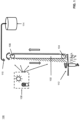
- the system 100 includes one or more rotating growing mats 102.
- the mats are suspended vertically.
- the mats are arranged between rollers 104 and 106.
- the growth of vegetation on a particular side of the mat may be encouraged by the appropriate application of light and nutrients, for example, water.
- the light may be provided by one or more natural and/or artificial light sources 108.
- the light may be provided by the sun and/or one or more light emitting diodes (LEDs).
- the LEDs are red and/or blue and may and may be high efficiency.
- water and other nutrients may be provided, for example, by a nozzle 110.
- the nozzle 110 is positioned on an optimized growth side. In this example, as the vegetation moves into the region of increased light levels, ideal conditions for the rapid vegetation growth are provided and the growth process is maintained. In certain aspects, on the other side of the mat 102, growth continues but at a lower rate due to the lower availability of water, nutrients, and/or light.
- the nutrients and/or water may be obtained, for instance, from storage 114.
- the mat comprises a growth side and an inhibited side.
- the side exposed to light, water, and/or nutrients may be a growth side, while the other side is an inhibited side.
- the inhibited side may be shielded from one or more of nutrients, light, and/or water.
- the rollers 104, 106 are configured such that a mass of the mat's growth side is greater than a mass on the inhibited side, and as a result, the growth side falls downward and the inhibited side moves upward.
- the mass of vegetation grown on a first side may be greater than the mass of vegetation grown on the inhibited side. In this way, the mat rotates according to the growth of the vegetation.
- growing mat 102 has a first side and a second side.
- the first side may include, for instance, a backing layer and the second side may include, for instance, a plurality of growing pockets.
- these may be comprised of porous Kevlar and cotton wool and containing a seeded growing compost.
- a strong backing layer is provided with a series of growing pockets made from porous Kevlar netting stitched onto the outermost side.
- a low density material such as cotton wool mixed with a seeded growing compost fills the pockets and is used initiate the growing process. Once the root system is fully established through the Kevlar netting, the pockets effectively become a single growing layer.
- System 100 may further include a cutting device 112, such as, for example, a rotating blade or strimming implement.
- the cutting device 112 may be located, for instance, below mat 102, and in some instances, below roller 104.
- the cutting device may be integral to the other components of system 100, or moveable.
- the cutting device may be moveable such that it may be used on multiple growth mats.
- the cutting device 112 can be used to release the excess vegetation from the mat 102, for instance, at the bottom of the optimized growth side.
- the cutting device 112 can also be located on a side of the growth mat 102. According to the invention, the mass of the mat on the optimized growth side is greater than the inhibited side such that the mat falls downwards on the optimized side and upwards on the inhibited side.
- the cutting device 112 is optimized to provide partial processing of the vegetation for use as feedstock. In some applications, it may be important for maximum conversion of plant matter to methane and carbon dioxide that the vegetation is cut into the smallest pieces possible to allow anaerobe microscopic organisms access to the inside of the cellular structure such as cellulose, etc.
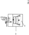
- the processing of the vegetation may be optimized through the use of a cryogenic milling mechanism 202.
- the mechanism 202 may be part of cutting device 112, in some embodiments.
- the cut vegetation is frozen to cryogenic temperatures, where the cell structure can be further disintegrated through crushing action on the now brittle plant material. The freezing may be accomplished, for instance, using liquid nitrogen or liquid air 204. After freezing, and in certain aspects, the thawing process of the vegetation may rupture the cell walls of the vegetation.
- the rotating growth mat 102 is arranged such that mechanical energy is released as the mat rotates, for instance, as the heavier side of the mat lowers itself. This energy can be captured and used for at least one of powering the cutting device, moving at least one of said plurality of rollers, powering a conveyor belt, and powering a compressor.
- the mechanical energy can be captured through a suitably geared mechanism that uses the mats unbalanced weight as a potential energy reservoir.
- the stored potential energy in the growing mat could be used to increase the overall efficiency of the system by being used, for example, to power the cutting device 112 to remove another strip of vegetation from the bottom of the mat, move the position of the rollers, power a conveyor belt collecting the released foliage, pump nutrients back up to the top roller position, and/or power a compressor used in the preprocessing of the vegetation feedstock of the cleaning and liquefaction of the resulting biogas from a following anaerobic digestion process.
- This energy could also be stored in a large spring similar to that of a clock so that when built up over time it can be released through a suitable control circuit or other mechanism.
- the stored energy could be used, for example, at night time to power a generator, for instance, to provide the light that can be used to maintain the photosynthesis of the grass during night time hours or when it is cloudy.
- a growing, falling/rotating, and cutting process is repeated continuously. For instance, as long as the mat on the optimized growth side is heavier than the inhibited growth side, it will cause indefinite rotation of the mat provided that there are nutrients, water, and/or light available to the optimized growth side.
- Intermittent renewable energy sources such as wind, solar, tidal, hydro-electric and wave power may be used in the systems of certain embodiments.
- such sources may have the limitation that they will often produce electricity when there is not a requirement for it, such as at night or during more favorable seasonal months when demand is lower.
- some embodiments can make use of both natural light and artificial light.
- a growing arrangement 300 which uses a plurality of growing mats 302, 304.
- a plurality of systems 100 may be arranged together in series.
- the growing mats 302, 304 may be arranged in a row (1, 2 ... n mats) to increase the growing area available for a given land area dramatically. This results in a corresponding increase in the yield of vegetation and the resulting anaerobic digester products per unit area.
- a cutting device 306 may be used to extract vegetation from more than one mat at the same time.
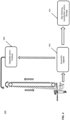
- a system 400 for generating a gas or liquid, such as methane is provided in accordance with some embodiments.
- one or more growing mats may be used in connection with an anaerobic digestion process.
- a system 100 as described with respect to FIG. 1 can be coupled to an anaerobic digester 402.
- the released vegetation can be used as the substrate fed to an anaerobic digester, which can be further processed.
- anaerobic digester 402 can be coupled to a gas cleaning, liquefaction, and/or storage stage 404.
- the vegetation may be processed to make digestate and/or fertilizer, which can be stored 406.
- the storage of digestate and/or fertilizer made from the vegetation of system 100 may be, for instance, storage 114 of FIG. 1 .
- the methane and carbon dioxide generated through the anaerobic digestion, cleaning, and/or liquefaction processes are valuable products, and the digestate and/or fertilizer can be used to complete the growing cycle.
- one or more of anaerobic digestion 402, and gas cleaning, liquefaction, and/or storage 404 can be performed, for example, using system 500, which is illustrated in FIG. 5 .
- System 500 may be, for instance, a part of a micro-anaerobic digestion (micro-AD) unit.
- micro-AD micro-anaerobic digestion
- system 500 includes at least one inlet valve 502. Methane gas or liquid methane gas may be introduced into storage vessel 510 via the inlet valve 502.
- the storage vessel 510 may be, for instance, a Dewar.
- a cooling unit 504 is configured to cool the methane gas or liquid methane gas within the storage vessel 510.
- the cooling unit may include, for instance, a closed cycle refrigerator 506 and closed cycle refrigeration head 508.
- the head 508 when the head 508 is cooled to a temperature below the condensing temperature of methane gas, liquid methane condenses on the head 508. The condensed liquid methane will run off head 508 into the main liquid methane reservoir 512.
- mains electricity is available to the system 500.
- a mains power line 518 may be attached to a power supply/inverter 514, which is used to maintain a power storage device, such as battery 520, at a maximum charge level.
- a microcontroller 516 which may include one or more processors, is also provided and attached to power line 518.
- the power supply/inverter 514 and microcontroller 516 may be provided as a single unit, or alternatively, as independent devices.
- the unit may also include one or more transceivers and antennas connected to microcontroller 516, for instance, to enable communication with external devices, such as a central controller, other micro-AD units, or user electronics.
- One or more of the battery 520 and power supply/inverter 514 can be used to power cooling unit 504, for instance, providing power to closed cycle refrigerator 506 to manage boil-off of the liquid methane of reservoir 512.
- the refrigerator 506 can be controlled to prevent any boil-off of the liquid methane of reservoir 512.
- the storage period of the liquid methane may be indefinite, as the unit can be configured such that there is no pressurization occurring within reservoir 512.
- the system 500 may include a pressure valve 524 to release boil-off methane.
- the valve 524 may be configured to release boil-off at a preset level into a buffer reservoir 526.
- the gaseous methane of the buffer reservoir may be used as fuel for one or more power generators of the system 500.
- a power generator 528 may be started and powered by the gaseous methane of buffer reservoir 526.
- the power generator may be any source capable of providing sufficient electrical power to cooling unit 504, such as an internal combustion (IC) generator or fuel cell. Additionally, the power generator may provide power to cutting device 112 or a light source 108.
- the IC engine output power may be sized such that sufficient electrical power is generated to allow full charging of battery 520 while simultaneously providing sufficient power to the closed cycle refrigerator 506.
- the generator 528 may include a CO 2 and/or H 2 O exhaust 546.
- the system 500 is configured for the extraction of methane gas "on-demand.”
- the on demand extraction of energy may be, for example, to power one or more components of system 100, 300, 400, and/or 1000.
- This extraction may be through a main output valve 530.
- an internal heater 532, such as a resistive heater, of the main reservoir 512 can be used to intentionally increase boil-off and increase Dewar pressure for release of either methane gas or liquid methane.
- Liquid methane can be released through a liquid methane take-off port 534.
- this heat could be supplied by reversing the closed cycle refrigerator 506 polarity such that it draws heat from the outside of the Dewar and transfers it to the main reservoir.
- internet connectivity 536 can be incorporated to allow the microcontroller 516 to send a status update or alarm to the unit owner or supplier. This also allows for remote control or inspection of the system to be carried out by the owner or supplier.
- an outer layer of solid insulation 538 such as low density polystyrene or other insulating material, can be incorporated to limit the excess boil-off resulting from a sudden loss of vacuum.
- the generator 528 can be rated to readily accept all boil-off resulting from such a scenario with all energy diverted to the coldhead 508 or resistive ballast in the microcontroller 516 as appropriate.
- the system 500 may be provided with additional safeguards such as a high pressure release valve 540.
- a safeguard may be used, for instance, following a failure of the closed cycle refrigerator 506 and simultaneous failure of the generator 528.
- the boil-off may flow to a flame containment vessel 542, such as a metal gauze cavity.
- the pressure release valve 540 can be configured to trigger a mechanical igniter 544 to ignite the resulting boil-off converting the methane to CO 2 and H 2 O in a controlled flare.
- gas generated in an anaerobic digester 602 can be stored in a gas buffer 604 and tank 610. This may correspond, for instance, to anaerobic digestion 402, and gas cleaning, liquefaction, and/or storage 404 in FIG. 4 .
- the gas may be stored in the buffer 604, for example, until a predetermined pressure is reached.
- a compressor 606 is started and the gas is circulated from the buffer through the compressor 606.
- the compressor 606 may be started, for example, once the predetermined pressure in buffer 604 is reached.
- the compressed gas may then be passed to an optional cleaning stage 608.
- the compressed gas is circulated to a storage tank 610 via inlet 612 that includes a heat exchanger 614.
- heat exchanger 614 may include finned heat exchanger tubing.
- the gas may be expanded through an orifice of heat exchanger 614 for cooling, or alternatively, a variable needle valve.
- liquefied methane collects in the storage tank 610, which may be, for example, a Dewar.
- the system 600 may also include one or more control valves 618 to regulate pressure and control gas flow.
- the liquid methane may be removed from storage tank 610 as needed, for instance, via a decanter 620.
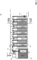
- an anaerobic digester 700 may be a part of system 400, and coupled to storage system 500.
- digester 700 can provide the input to system 500 at inlet 502.
- the anaerobic digester 700 comprises multiple tanks (702,704); however, digester 700 could include of a single tank 702.
- the tanks may be relatively small, and the total number of tanks may be set according to a customer's intended use and/or the amount of land that will be used to supply feedstock.
- a PH gradient and temperature gradient can be maintained across the tanks.
- the digester 700 may further include an inlet 706 for receiving feedstock and, optionally, a macerator 708 to mulch, agitate and/or separate components of the feedstock during anaerobic digestion.
- the inlet 706 may receive vegetation as a feedstock, for instance, from growth mat 102.
- the vegetation from growth mat 102 may be cut by cutting device 112 prior to input to digester 700.
- the feedstock input to digester 700 may be a combination of grass and/or water; however, digester 700 is not necessarily limited to such an input.
- the processing of the vegetation used in digester 700 may be optimized through the use of cryogenic milling mechanism 202, as illustrated in FIG. 2 .
- the gas output from each tank is controlled via a latching gas valve 710,712.
- the valve may be remotely controllable, for instance, via local or remote computer. If a quantity of substrate (e.g. , partially digested feedstock) is required to be moved from one tank to the next, for instance, from tank 702 to tank 704, the gas output of the sending tank 702 can be turned off using gas valve 710. However, the gas output valve 712 of the receiving tank 704 is left open. The gas pressure in the sending tank 702 is then allowed to build up and as a result the substrate is forced though the outlet pipe 714 and into the receiving tank 704.
- substrate e.g. , partially digested feedstock
- the gas pressure from the sending tank 702 is relieved to a point at which transfer stops.
- the gas pressure may then be maintained at this level to prevent re-syphoning of the substrate.
- the pressure can be completely released to allow the levels of the tanks 702,704 to re-equalize.
- one tank of digester 700 is left intentionally empty. In certain embodiments, at least one tank is always left empty.
- the process is returned to an aerobic digestion state to compost any residual organic matter and/or remove any unpleasant odors before expelling the digestate, for instance, via an outlet valve 716.
- digestate and/or fertilizer generated in an anaerobic digestion process for instance in digester 700, can be used in connection with vegetation growth as illustrated in FIG.4 .
- digestate and/or fertilizer 406 may be obtained from digester 700.
- pressure in the final tank or "stage" of a multi-tank/stage anaerobic digester can be allowed to build up to a desired pressure.
- Pressure build-up can be controlled, for example, by adjusting one or more valves of the digester and/or increasing temperature.
- the desired pressure is high enough that a compressor in subsequent processing stages is not required. For instance, if the pressure is allowed to build to a high enough level, for example between 2 and 30 bar, it may be possible to eliminate compressors that would otherwise be needed during cleaning or liquification, such as compressor 808 of FIG. 8 or compressor 606 of FIG. 6 .
- the pressure in a final stage of anaerobic digester 602 can be allowed to increase such that naturally pressurized biogas is fed to heat exchanger 614, which may include finned heat exchanger tubing.
- heat exchanger 614 which may include finned heat exchanger tubing.
- naturally pressurized biogas may by passed through filter 816 onto heat exchanger 812, which may also include finned heat exchanger tubing.
- the cleaning and/or liquification process can be effectively powered by the anaerobic digestion process itself and the associated microbes. This may include, for example, gas cleaning, liquefaction, and/or storage 404 of system 400, as illustrated in FIG. 4 .
- the removal stage 800 includes an inlet 802, and outlet 804, and a CO 2 storage unit 806.
- the stage 800 further includes a number of compressors (808,810) and heat exchangers (812,814), as well as an optional hydrogen sulphide filter 816.
- the inlet 802 is connected to a biogas source.
- inlet 802 may be connected to anaerobic digester 700 illustrated in FIG. 7 .
- Outlet 804 may be coupled to a methane storage unit, such as system 500.
- outlet 804 may be connected directly to input valve 502.
- cryogenic cooling grinding and/or milling of the vegetation material can provide a pre-treatment of feedstock.
- Cryogenic pre-processing of vegetation can improve methane yield in subsequent processing.
- the cryogenic processing explodes the individual plant cells through the expansion of the water within the cytoplasm releasing the inner readily anaerobically digestible organic contents from the lignin rich outer cell wall, which can be difficult for the anaerobes to digest.
- the expansion may occur, for instance, as part of a thawing process. This can greatly increase the biogas, and therefore methane yield, and also reduce the retention time, thereby increasing throughput.
- Such a process could, for example, improve the performance of system 400.
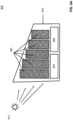
- FIG. 9A a layout 900, for instance in greenhouse 904, is illustrated in a side view.
- mats 902 are arranged in greenhouse 904 with light source, e.g., the sun, 910.
- an anaerobic digester 906 and gas cleaning, liquefaction, and/or storage stage 908 are co-located with the mats 902.
- the position of one or more of mats 902 can be varied. The varying is performed, for instance, based on the position of the sun 910 to improve growth efficiency. For instance, as illustrated with respect to FIG.
- FIG. 9B a top view of layout 900 is shown with mats 902 positioned based on the location of the sun 910.
- This layout may correspond, for instance, to a morning time.
- FIG. 9C the position of mats 902 may be varied as the location of the sun 910 changes. This layout may correspond, for instance, to midday.
- FIG. 9D the position of mats 902 may be varied again as the position of location of the sun 910 as it changes. This layout may correspond, for instance, to evening.
- vertical growth mats 1002 may be arranged in a stacked configuration 1000 to further increase the effective growing area.
- the mats are arranged to receive light from a source 1008, and are co-located with an anaerobic digester 1004 and gas cleaning, liquefaction, and/or storage stage 1006.
- light source 1008 may be the sun or an artificial light source, such as a high efficiency red or blue LED.
- mats 1002 may be arranged on rollers as described with respect to FIG. 1 and system 100. Additionally, the position of mats 1002 may be variable according to the location of the sun, for instance, as described with respect to FIGs. 9A-9D .
- a vertical suspended growing mat may be used in conjunction with a uniformly flat vegetation such as grass, and a simple harvesting technique such as mowing, for example, it is possible to efficiently make use of the vertical volume above what would be the natural growing area available.
- the yield therefore increases exponentially for a given land area in accordance with some embodiments.
- the anaerobic digestion of cuttings taken from one hectare of lawn grass, (approximately two football fields) will produce approximately 12 thousand liters of liquid methane per annum.
- the yield would be 1.2 million liters of methane, an increase of one hundredfold. This represents a significant development for the introduction of zero carbon methane and the corresponding carbon emissions.
- Process 1100 may be performed, for instance, using systems 100, 300, and 400 of FIGs. 1 , 3 , and 4 , respectively. Additionally, process 1100 may be performed using the stacked arrangement of mats illustrated in FIG. 10 and/or the offshore arrangement of FIG. 17 .
- Process 1100 may begin, for instance, with step 1110.
- electricity is obtained from an external source.
- the external source may be, for example, a renewable energy source such as one or more of wind, wave, solar, tidal and hydro-electric.
- the electricity may also be obtained from a mains electricity source.
- the electricity is obtained at a below-average cost due to one or more of time of day and season.
- the electricity may be obtained from a source locally generating electricity at the offshore platform.
- an artificial light source is operated using the electricity to deliver light energy to a growth surface of a vertical growth mat.
- the process 1100 may also include providing natural light as well. This may enable, for instance, continuous growth of the vegetation through the combination of natural and artificial light.
- the position of the growth mats may be varied based on the position of the sun.
- the vertical growth mat is mounted on a plurality of rollers for rotatable movement. Further, mechanical energy released from the movement of the vertical growth mat can be captured and then used in the growth process. For example, the captured energy can be used for powering a cutting device (e.g., in step 1130), moving a roller, powering a conveyor belt, and/or powering a compressor.
- a cutting device is operated.
- the cutting device can be configured to cut vegetation grown on the growth surface of the vertical growth mat.
- step 1140 an anaerobic digester coupled to the cutting device is used to generate methane.
- step 1140 is optional.
- the methane may be stored for subsequent use.
- the process 1100 may also include delivering nutrients to the vertical growth mat.
- the nutrients could include by-products obtained from the anaerobic digester.
- Process 1200 may be performed, for instance, using systems 100, 300, and 400 of FIGs. 1 , 3 , and 4 , respectively. Additionally, process 1200 may be performed using the stacked arrangement of mats illustrated in FIG. 10 and/or the offshore arrangement of FIG. 17 .
- Process 1200 may begin, for instance, with step 1210, in which nutrients are delivered to one or more vertical growth mats of a vertical growth system.
- the nutrients may include, for example one or more of fertilizer and or water.
- step 1220 light energy is delivered to the one or more growth mats.
- the light energy may be from an artificial and/or natural light source.
- step 1230 a cutting device is operated to cut vegetation grown on the growth mats.
- at least one of the vertical growth mats of the system is suspended vertically on a roller.
- the delivery of nutrients and/or delivery of light energy is performed such that a first mass of vegetation grown on a first side of the growth mat is greater than a second mass of vegetation grown on a second side of the growth mat. As a result, the first side falls downward and the second side moves upward.
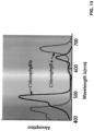
- the growth and processing of vegetation using the system and method disclosed can have numerous advantages. For example, intermittent renewable energy sources often produce energy during the night time when energy requirements are low. Instead of switching off or dumping this electricity, it can be used to provide artificial light to allow a 24-hour growth period. This light could consist of the use of very efficient light emitting diode technologies centered at wavelengths in the red and blue part of the visible spectrum. This can increase the overall efficiency of the systems and processes disclosed herein. By way of illustration, optimum wavelengths for photosynthesis are shown in FIG. 13 , where the absorption properties as a function of wavelength for chlorophyll types (a) and (b) are depicted. Additionally, the rate of photosynthesis is closely related to these optimum wavelengths as shown in FIG. 14 . According to some embodiments, the waste heat from the light emitting diodes can be utilized to provide heat in colder climates in which to enhance the growth rates of the grass or other chosen feedstock.
- the optimum natural light level can be achieved for most efficient growth depending on the intensity and angle of the Sun's illuminati relative to the vertical axis.
- the position of each row can be varied throughout the day to track the solar flux and increase efficiency.
- the photosynthetic efficiency can be calculated as the energy capture and derived from the light absorption used in particular pathways to achieve the final result of synthesis of sugars. It is known that a total of 8 photons of light must be absorbed to reduce two molecules of NADP+. Operating in the Calvin cycle, the resulting two molecules of NADPH can produce one hexose molecule.
- Some embodiments disclosed herein provide an exponentially scalable non-intermittent storable renewable energy source that can be positioned on either land or sea, but rely primarily on sunlight for its energy capture.
- the generation of biogas, as well as production of methane and/or carbon dioxide can be combined with the intermediary generation of liquid air from air extracted from the local environment using intermittent renewable energy sources such as wind, wave, solar, tidal and hydro. That is, according to some embodiments, the generation and use of liquid air from renewable sources can be combined with the subsequent cleaning and liquefaction of carbon dioxide and methane processes for converting energy.
- the process 1500 may produce, for instance, non-intermittent renewable energy.
- the process 1500 shown in FIG. 15 may utilize a renewable power source 1502, which in some examples, does not need to be connected to any electricity or gas grid.
- element 1502 is illustrated as a wind source, but it could be wave, solar, tidal and/or hydro in other examples.
- a cryogenic generation system 1504 can be used to create a supply of liquid air extracted from the environment.
- the process 1500 may also optionally include storage of the liquid air, for instance in a cryogenic storage vessel for the liquid air 1506.
- the liquid air processing of 1502, 1504, and 1506 may be coupled to biogas generation and processing 1508. For example, they may be coupled to a system 100, 300,400, and/or 1000 as provided in FIGs. 1 , 3 , 4 , and 10 , respectively.
- the cleaning of biogas involves the separation of three primary constituents: Sulphur dioxide, carbon dioxide, and methane.
- this can be most readily achieved using cryogenic processing such as the Linde distillation process.
- cryogenic processing such as the Linde distillation process.
- the subsequent liquefaction process of the carbon dioxide and methane may be complicated by the explosive nature of methane. Liquefaction of a gas is most readily achieved through the compression, cooling and then rapid expansion of the gas, at which point it is cooled below its liquefaction temperature to form a liquid.
- this process requires electrical power to drive a compressor, and the compressor must be designed to be safe, which increases its cost and complexity.
- this process can be used to separate and subsequently liquefy firstly carbon dioxide and then methane due to their very different liquefaction temperatures of - 37C and -161C, respectively.
- the compression of methane typically requires expensive electro-mechanical equipment which is required to comply with strict safety guidelines such as ATEX. This makes the process both expensive and complicated, making the subsequent products comparable in price to existing fossil fuels.
- embodiments disclosed herein may use the relatively safe and convenient properties of liquid air as an intermediary source of cold from which the liquefaction of methane and carbon diode can be achieved passively by passing the liquid air and methane and carbon dioxide mixture through either side of a heat exchanger.
- liquid air may be produced on an industrial scale anywhere on planet Earth through the use of well-known techniques such as the Linde process in its formation. Thus, and in some embodiments, it makes an ideal source of cold in remote areas, such as offshore in the ocean or in a desert. In certain aspects, all that is required is a mechanically driven compressor which can be driven by renewable sources. Also, unlike methane, liquid air is relatively inert and so the safety requirements for its distillation and liquefaction are straightforward. In certain aspects, as a liquid, it represents a convenient medium in which to store cold, which can be used for both the cryogenic milling and biogas cleaning, separation and liquefaction .
- liquid nitrogen may be used - in connection with the cryogenic milling illustrated in FIG. 2 .
- compressors which if driven either mechanically directly or indirectly from electricity generated from intermittent renewable energy sources such as wind, hydro, solar, tidal and wave power it can be stored for long periods greatly in excess of the intermittency period.
- intermittent renewable energy sources such as wind, hydro, solar, tidal and wave power it can be stored for long periods greatly in excess of the intermittency period.
- the energy used to liquefy it can be partially recovered by allowing it to expand as it warms and using the pressure generated to drive a compressor in reverse to derive mechanical energy.
- liquid air is so easily created, handled, and stored, and combined with the fact that it can be made from air anywhere on planet Earth and it exists as a liquid at a lower temperature (-195C) than both methane and carbon dioxide, its use represents a convenient intermediary medium that can be used to first separate and then create both liquid methane and liquid carbon dioxide without the need for expensive explosion proof electro-mechanical equipment that would be used to handle methane. According to some embodiments, this can be achieved simply by passing firstly the carbon dioxide gas and then methane under gravity, over a simple heat exchanger through which cold liquid from the natural boil-off from the liquid air reservoir is flowing. This will cause both gases to condense into a liquid. This greatly simplifies and reduces the cost of both the separation and liquefaction of both carbon dioxide and methane.
- liquid air or one of its derivatives liquid nitrogen provides a convenient supply of cold.
- liquid air or one of its derivatives can remove the need for a supply of electricity or partial use of the resulting biogas for its production. This can result in a further reduction in production cost and/or increase in biomethane and carbon dioxide yield.
- a method 1600 for the processing of biogas is provided.
- the method may begin at step 1610, which includes generating liquid air.
- the liquid air can be generated by operating a mechanical compressor to compress and cool air.
- the generation of the liquid air is performed using one or more of wind, hydro, solar, tidal, and/or wave power sources. These sources can directly power the process, or alternatively, generate electricity to power the process.
- biogas is obtained.
- obtaining the biogas includes performing anaerobic digestion. For instance, using one or more of systems 100, 300, 400, and/or 1000 as provided in FIGs. 1 , 3 , 4 , and 10 , respectively, biogas can be obtained by performing anaerobic digestion on vegetation obtained from a vertical growth mat.
- step 1630 carbon dioxide and methane are created from the biogas using the liquid air of step 1610.
- this includes passing the liquid air and biogas through a heat exchanger to form liquid methane and liquid carbon dioxide.
- the method 1600 can include operating a cryogenic milling device to disintegrate vegetation, where the milling device uses liquid air or a derivative of liquid air, such as liquid nitrogen.
- FIG. 17 illustrates an example 1700 of how embodiments may be implemented in an offshore platform 1702 with tanker 1704.
- one or more systems 1706 for growing vegetation in accordance with disclosed embodiments, including systems illustrated in FIGs. 4 and 10 can be implemented on platform 1702.
- an offshore location also has an advantage that it does not need to make use of land. For example, there may be no need for land rental or purchase, particularly if implemented in international waters.
- offshore implementation 1700 may also have an advantage over other offshore energy generation schemes in that there is no need to connect the system to any electrical grid or pipeline.
- the output of the system 1706 can be liquid biomethane, which has an energy density that is comparable to oil based fuels and can be removed from the system by fuel tanker 1704.
- offshore implementation can also make use of one or more materials and energy sources found in offshore locations, and particularly in international waters. This includes, for instance, air, sunlight, water (sea and rain), wind and waves.
- Implementation 1700 can be positioned far out to sea, e.g., in international waters, where there is minimal visual impact and there is potentially no need for government permissions. In certain aspects, it can also be moved if necessary during seasonal solar, rain, wind or wave fluctuations.
- Offshore locations tend to be windier than land locations and may also have access to tidal and wave power. They may also be subject to relatively predictable daily or seasonal winds tides and swells emanating from lunar, geographical and solar conditions.
- a platform 1702 positioned in an offshore location in the vicinity of an inland desert may be subject to strong alternating onshore and offshore winds caused by the diurnal heating and cooling of the desert relative to the constant temperature of the sea. These regular winds, which would otherwise be difficult to exploit due to the lack of electricity grid infrastructure usually occurring in such a remote location, can be captured via windmill 1708.
- a windmill is depicted in this example, other renewable sources may be used, such as solar, tidal, and hydro-electric electricity sources.
Landscapes
- Life Sciences & Earth Sciences (AREA)
- Engineering & Computer Science (AREA)
- Chemical & Material Sciences (AREA)
- Health & Medical Sciences (AREA)
- Organic Chemistry (AREA)
- Wood Science & Technology (AREA)
- Zoology (AREA)
- Bioinformatics & Cheminformatics (AREA)
- Environmental Sciences (AREA)
- Genetics & Genomics (AREA)
- Microbiology (AREA)
- Biotechnology (AREA)
- Biochemistry (AREA)
- General Engineering & Computer Science (AREA)
- General Health & Medical Sciences (AREA)
- Sustainable Development (AREA)
- Biomedical Technology (AREA)
- Molecular Biology (AREA)
- Forests & Forestry (AREA)
- Ecology (AREA)
- Biodiversity & Conservation Biology (AREA)
- General Chemical & Material Sciences (AREA)
- Combustion & Propulsion (AREA)
- Mechanical Engineering (AREA)
- Chemical Kinetics & Catalysis (AREA)
- Oil, Petroleum & Natural Gas (AREA)
- Structural Engineering (AREA)
- Architecture (AREA)
- Civil Engineering (AREA)
- Ocean & Marine Engineering (AREA)
- Botany (AREA)
- Food Science & Technology (AREA)
- Water Supply & Treatment (AREA)
- Environmental & Geological Engineering (AREA)
- Hydrology & Water Resources (AREA)
- Hydroponics (AREA)
- Cultivation Of Plants (AREA)
Claims (9)
- Système (100) permettant de faire pousser une végétation, comprenant :un tapis de croissance rotatif (102) ;une pluralité de rouleaux (104, 106), ledit tapis de croissance rotatif étant suspendu verticalement à au moins l'un de ladite pluralité de rouleaux ; etun dispositif de coupe (112),ledit tapis comprenant un côté de croissance et un côté inhibé,ledit dispositif de coupe étant conçu pour couper la végétation poussant sur ledit côté de croissance dudit tapis de croissance rotatif, caractérisé en ce queladite pluralité de rouleaux est conçue de sorte qu'une masse du tapis sur le côté de croissance soit supérieure à une masse sur le côté inhibé et que, par conséquent, le côté de croissance tombe et le côté inhibé se déplace vers le haut.
- Système selon la revendication 1, ledit dispositif de coupe étant accouplé à un dispositif de broyage cryogénique (202) conçu pour désintégrer ladite végétation cultivée sur ledit tapis de croissance.
- Système selon la revendication 1 ou 2, comprenant en outre :un dispositif d'apport de nutriments (110) positionné à côté d'un côté de croissance dudit tapis de croissance ; etune source de lumière artificielle (108).
- Système selon la revendication 3, ladite source de lumière artificielle étant une diode électroluminescente rouge ou bleue.
- Système selon la revendication 1, comprenant en outre :
un système de digestion anaérobie (402), ledit système de digestion anaérobie étant conçu pour fonctionner à l'aide de la végétation cultivée sur ledit tapis de croissance rotatif et traitée par ledit dispositif de coupe. - Système selon la revendication 1, ledit tapis de croissance comprenant une couche de support et une pluralité de poches de croissance contenant du compost pour la croissance des semences.
- Système (100) selon la revendication 5, comprenant :une ou plusieurs sources de lumière artificielle (108) ;une pluralité de tapis de croissance verticaux (102) ;chacun de ladite pluralité de tapis de croissance rotatifs étant suspendu verticalement à au moins un de ladite pluralité de rouleaux et comprenant un côté de croissance et un côté inhibé, un ou plusieurs dispositifs de coupe (112) ; etledit système de digestion anaérobie (402) étant conçu pour fonctionner à l'aide de la végétation poussant sur ladite pluralité de tapis de croissance verticaux et traitée par ledit dispositif de coupe,un premier de ladite pluralité de tapis de croissance verticaux étant situé au-dessus d'un second de ladite pluralité de tapis de croissance,ladite pluralité de tapis de croissance verticaux étant disposée en au moins une rangée et la position de ladite au moins une rangée étant variable en fonction de la position du soleil.
- Système (1700) selon la revendication 1, permettant de faire pousser une végétation en mer, comprenant :un système de digestion anaérobie conçu pour fonctionner à l'aide de ladite végétation poussant sur ledit tapis de croissance rotatif et traitée par ledit dispositif de coupe ; etune plate-forme en mer (1702), lesdits tapis de croissance rotatif, dispositif de coupe et système de digestion anaérobie étant situés sur ladite plate-forme en mer.
- Système selon la revendication 8, comprenant en outre :
une ou plusieurs sources de lumière artificielle, au moins une desdites une ou plusieurs sources de lumière artificielle étant alimentée par au moins une d'une source d'électricité éolienne, solaire, marémotrice ou hydroélectrique sur ladite plate-forme en mer.
Applications Claiming Priority (2)
| Application Number | Priority Date | Filing Date | Title |
|---|---|---|---|
| US201662295893P | 2016-02-16 | 2016-02-16 | |
| PCT/IB2017/050854 WO2017141178A1 (fr) | 2016-02-16 | 2017-02-16 | Systèmes et procédés permettant de faire pousser une végétation |
Publications (2)
| Publication Number | Publication Date |
|---|---|
| EP3416475A1 EP3416475A1 (fr) | 2018-12-26 |
| EP3416475B1 true EP3416475B1 (fr) | 2023-11-01 |
Family
ID=58191505
Family Applications (1)
| Application Number | Title | Priority Date | Filing Date |
|---|---|---|---|
| EP17707958.9A Active EP3416475B1 (fr) | 2016-02-16 | 2017-02-16 | Système permettant de faire pousser une végétation |
Country Status (5)
| Country | Link |
|---|---|
| US (1) | US11291161B2 (fr) |
| EP (1) | EP3416475B1 (fr) |
| CN (1) | CN109068601B (fr) |
| ES (1) | ES2968018T3 (fr) |
| WO (1) | WO2017141178A1 (fr) |
Families Citing this family (6)
| Publication number | Priority date | Publication date | Assignee | Title |
|---|---|---|---|---|
| US12284954B2 (en) * | 2017-05-30 | 2025-04-29 | Fraunhofer-Gesellschaft Zur Foerderung Der Angewandten Forschung E.V. | Device for promoting the growth of plants |
| DK3409103T3 (da) * | 2017-05-30 | 2021-10-25 | Fraunhofer Ges Forschung | Anordning og fremgangsmåde til fremme af planters vækst |
| DE102021134167B4 (de) | 2021-08-22 | 2024-03-14 | AI.Land GmbH | Vorrichtung und Verfahren zur automatisierten Förderung des Wachstums von Pflanzen, insbesondere von nachwachsenden Kulturen |
| EP4147568A1 (fr) * | 2021-09-13 | 2023-03-15 | Fraunhofer-Gesellschaft zur Förderung der angewandten Forschung e.V. | Dispositif et procédé d'approvisionnement en nutriments des plantes et des champignons |
| WO2024054156A1 (fr) * | 2022-09-06 | 2024-03-14 | Hung Guan ONG | Système et procédé de culture verticale |
| EP4686759A1 (fr) | 2024-07-30 | 2026-02-04 | WCHF Europe j. s. a. | Procede de production de biocarburant utilisant des sous-systèmes de germination et de biogaz interreliés de manière opérationnelle, et le sous-système de germination |
Citations (3)
| Publication number | Priority date | Publication date | Assignee | Title |
|---|---|---|---|---|
| WO2004071193A2 (fr) * | 2003-02-12 | 2004-08-26 | Koch Cellulose, Llc | Lit de semence pour la croissance de vegetation |
| US20050132968A1 (en) * | 2003-11-17 | 2005-06-23 | Swank Richard B. | Agglomerated animal litter and manufacturing process for the same |
| US20090215141A1 (en) * | 2008-02-22 | 2009-08-27 | David Tessel | Biofuel generating system |
Family Cites Families (14)
| Publication number | Priority date | Publication date | Assignee | Title |
|---|---|---|---|---|
| US3300896A (en) | 1965-05-10 | 1967-01-31 | Res Engineering Co | Hydroponic growth of plants |
| US3425158A (en) | 1967-01-26 | 1969-02-04 | Leslie B Kyle | Culture belt for a hydroponic system |
| DE1782764A1 (de) * | 1967-02-28 | 1972-08-03 | Karl Oepen | Vorrichtung zur Beschickung einer Pflanzenwachstumsanlage mit Saatgut |
| FR2529917A1 (fr) | 1982-07-06 | 1984-01-13 | Saint Gobain Isover | Procede et dispositif pour la formation de feutre de fibres contenant un produit additionnel |
| DE3817289A1 (de) * | 1988-05-20 | 1989-11-30 | Brehm International Marketing | Einrichtung zum fuettern von vieh |
| AU3940195A (en) * | 1994-11-24 | 1996-06-17 | Zero Grass (Nz) Limited | Biomass production |
| MXPA05009553A (es) * | 2003-03-10 | 2006-03-17 | Broin And Associates Inc | Metodo para producir etanol utilizando almidon como materia prima. |
| AU2003252206A1 (en) * | 2003-10-02 | 2005-04-21 | Peter Charles Glass | A Method and Apparatus for Hydroponically Growing Fodder or Rootlet Mat Crop |
| CN100999673A (zh) * | 2006-12-30 | 2007-07-18 | 孟知云 | 一种植物废弃物综合利用的方法 |
| CN101314780A (zh) * | 2007-05-29 | 2008-12-03 | 黄卫东 | 利用太阳能生产甲烷和电的方法 |
| CN101392019A (zh) * | 2008-10-30 | 2009-03-25 | 中国科学院新疆生态与地理研究所 | 沙冬青叶片抗冻蛋白的提取分离方法 |
| US20120308989A1 (en) * | 2009-06-02 | 2012-12-06 | Prometheus Technologies, Llc | Conversion of aquatic plants to liquid methane, and associated systems and methods |
| US20120085026A1 (en) * | 2010-10-12 | 2012-04-12 | Morris David W | Expandible aeroponic grow system |
| US8809026B2 (en) * | 2011-12-27 | 2014-08-19 | Commonwealth Scientific And Industrial Research Organisation | Processes for producing lipids |
-
2017
- 2017-02-16 EP EP17707958.9A patent/EP3416475B1/fr active Active
- 2017-02-16 WO PCT/IB2017/050854 patent/WO2017141178A1/fr not_active Ceased
- 2017-02-16 CN CN201780011790.5A patent/CN109068601B/zh active Active
- 2017-02-16 US US15/998,748 patent/US11291161B2/en active Active
- 2017-02-16 ES ES17707958T patent/ES2968018T3/es active Active
Patent Citations (3)
| Publication number | Priority date | Publication date | Assignee | Title |
|---|---|---|---|---|
| WO2004071193A2 (fr) * | 2003-02-12 | 2004-08-26 | Koch Cellulose, Llc | Lit de semence pour la croissance de vegetation |
| US20050132968A1 (en) * | 2003-11-17 | 2005-06-23 | Swank Richard B. | Agglomerated animal litter and manufacturing process for the same |
| US20090215141A1 (en) * | 2008-02-22 | 2009-08-27 | David Tessel | Biofuel generating system |
Also Published As
| Publication number | Publication date |
|---|---|
| WO2017141178A1 (fr) | 2017-08-24 |
| ES2968018T3 (es) | 2024-05-06 |
| US20200281132A1 (en) | 2020-09-10 |
| CN109068601A (zh) | 2018-12-21 |
| CN109068601B (zh) | 2021-08-24 |
| US11291161B2 (en) | 2022-04-05 |
| EP3416475A1 (fr) | 2018-12-26 |
Similar Documents
| Publication | Publication Date | Title |
|---|---|---|
| US11291161B2 (en) | Systems and methods for growing vegetation | |
| Hilarydoss | Suitability, sizing, economics, environmental impacts and limitations of solar photovoltaic water pumping system for groundwater irrigation—a brief review | |
| Smil | Power density: a key to understanding energy sources and uses | |
| US8991182B2 (en) | Increasing the efficiency of supplemented ocean thermal energy conversion (SOTEC) systems | |
| JP5852576B2 (ja) | 再生可能エネルギーの統合フルスペクトル生産を通じた持続可能な経済開発のためのシステム及び方法 | |
| CN101946070B (zh) | 太阳热能转换方法 | |
| CN101946134A (zh) | 太阳热能存储方法 | |
| US20120308989A1 (en) | Conversion of aquatic plants to liquid methane, and associated systems and methods | |
| Jha et al. | Clean energy technologies for sustainable food security | |
| dos Santos Isaías et al. | A review on renewable energy systems for irrigation in arid and semi-arid regions | |
| Otieno et al. | Energy resources in East Africa: Opportunities and challenges | |
| US9187724B1 (en) | Method to optimize the utilization of captured carbon dioxide through the cultivation and processing of microalgae | |
| Hayes | Energy: The Solar Prospect. Worldwatch Paper 11. | |
| JP2020089248A (ja) | 表面由来エネルギーの長期保存を勘案しての発電 | |
| Chivers | NoNonsense Renewable Energy: Cleaner, fairer ways to power the planet | |
| Ushakov | Electric power engineering on the basis of renewable energy sources | |
| Mulloney Jr | Mitigation of carbon dioxide releases from power production via “sustainable agri-power”: The synergistic combination of controlled environmental agriculture (large commercial greenhouses) and disbursed fuel cell power plants | |
| Sims | Energy-smart innovation and renewable energy systems on farms: an overview. | |
| Mehrotra | Integrating Renewable Energy Sources in Agriculture: A Holistic Approach to Sustainable Food Systems | |
| Cherne | Solar energy—An overview | |
| Parvez et al. | Role of Renewable Energy Resources in Meeting Global Energy Demand | |
| Poovamma | Renewable Energy in Agriculture | |
| Mohammad | Water desalination, purification, irrigation, and wastewater treatment | |
| Binzaid | GLOBAL WARMING, CO2, FOSSIL FUELS AND LIFE: A PHOTOTHERMAL ALTERNATIVE SOLUTION FOR SOLAR ENERGY ON-DEMAND | |
| Chambers | The design and development of heat extraction technologies for the utilisation of compost thermal energy |
Legal Events
| Date | Code | Title | Description |
|---|---|---|---|
| STAA | Information on the status of an ep patent application or granted ep patent |
Free format text: STATUS: UNKNOWN |
|
| STAA | Information on the status of an ep patent application or granted ep patent |
Free format text: STATUS: THE INTERNATIONAL PUBLICATION HAS BEEN MADE |
|
| PUAI | Public reference made under article 153(3) epc to a published international application that has entered the european phase |
Free format text: ORIGINAL CODE: 0009012 |
|
| STAA | Information on the status of an ep patent application or granted ep patent |
Free format text: STATUS: REQUEST FOR EXAMINATION WAS MADE |
|
| 17P | Request for examination filed |
Effective date: 20180917 |
|
| AK | Designated contracting states |
Kind code of ref document: A1 Designated state(s): AL AT BE BG CH CY CZ DE DK EE ES FI FR GB GR HR HU IE IS IT LI LT LU LV MC MK MT NL NO PL PT RO RS SE SI SK SM TR |
|
| AX | Request for extension of the european patent |
Extension state: BA ME |
|
| RIC1 | Information provided on ipc code assigned before grant |
Ipc: A01G 31/04 20060101AFI20170908BHEP Ipc: A01G 1/00 20060101ALI20170908BHEP |
|
| DAV | Request for validation of the european patent (deleted) | ||
| DAX | Request for extension of the european patent (deleted) | ||
| STAA | Information on the status of an ep patent application or granted ep patent |
Free format text: STATUS: EXAMINATION IS IN PROGRESS |
|
| 17Q | First examination report despatched |
Effective date: 20220701 |
|
| RIC1 | Information provided on ipc code assigned before grant |
Ipc: A01G 20/20 20180101ALI20230216BHEP Ipc: A01G 31/04 20060101AFI20230216BHEP |
|
| GRAP | Despatch of communication of intention to grant a patent |
Free format text: ORIGINAL CODE: EPIDOSNIGR1 |
|
| STAA | Information on the status of an ep patent application or granted ep patent |
Free format text: STATUS: GRANT OF PATENT IS INTENDED |
|
| INTG | Intention to grant announced |
Effective date: 20230511 |
|
| P01 | Opt-out of the competence of the unified patent court (upc) registered |
Effective date: 20230519 |
|
| GRAS | Grant fee paid |
Free format text: ORIGINAL CODE: EPIDOSNIGR3 |
|
| GRAA | (expected) grant |
Free format text: ORIGINAL CODE: 0009210 |
|
| STAA | Information on the status of an ep patent application or granted ep patent |
Free format text: STATUS: THE PATENT HAS BEEN GRANTED |
|
| AK | Designated contracting states |
Kind code of ref document: B1 Designated state(s): AL AT BE BG CH CY CZ DE DK EE ES FI FR GB GR HR HU IE IS IT LI LT LU LV MC MK MT NL NO PL PT RO RS SE SI SK SM TR |
|
| RAP3 | Party data changed (applicant data changed or rights of an application transferred) |
Owner name: BENNAMANN SERVICES LTD |
|
| REG | Reference to a national code |
Ref country code: GB Ref legal event code: FG4D |
|
| REG | Reference to a national code |
Ref country code: CH Ref legal event code: EP |
|
| REG | Reference to a national code |
Ref country code: IE Ref legal event code: FG4D |
|
| REG | Reference to a national code |
Ref country code: DE Ref legal event code: R096 Ref document number: 602017075953 Country of ref document: DE |
|
| REG | Reference to a national code |
Ref country code: NL Ref legal event code: FP |
|
| REG | Reference to a national code |
Ref country code: LT Ref legal event code: MG9D |
|
| PG25 | Lapsed in a contracting state [announced via postgrant information from national office to epo] |
Ref country code: GR Free format text: LAPSE BECAUSE OF FAILURE TO SUBMIT A TRANSLATION OF THE DESCRIPTION OR TO PAY THE FEE WITHIN THE PRESCRIBED TIME-LIMIT Effective date: 20240202 |
|
| PG25 | Lapsed in a contracting state [announced via postgrant information from national office to epo] |
Ref country code: IS Free format text: LAPSE BECAUSE OF FAILURE TO SUBMIT A TRANSLATION OF THE DESCRIPTION OR TO PAY THE FEE WITHIN THE PRESCRIBED TIME-LIMIT Effective date: 20240301 |
|
| PG25 | Lapsed in a contracting state [announced via postgrant information from national office to epo] |
Ref country code: LT Free format text: LAPSE BECAUSE OF FAILURE TO SUBMIT A TRANSLATION OF THE DESCRIPTION OR TO PAY THE FEE WITHIN THE PRESCRIBED TIME-LIMIT Effective date: 20231101 |
|
| REG | Reference to a national code |
Ref country code: AT Ref legal event code: MK05 Ref document number: 1626098 Country of ref document: AT Kind code of ref document: T Effective date: 20231101 |
|
| PG25 | Lapsed in a contracting state [announced via postgrant information from national office to epo] |
Ref country code: AT Free format text: LAPSE BECAUSE OF FAILURE TO SUBMIT A TRANSLATION OF THE DESCRIPTION OR TO PAY THE FEE WITHIN THE PRESCRIBED TIME-LIMIT Effective date: 20231101 |
|
| PG25 | Lapsed in a contracting state [announced via postgrant information from national office to epo] |
Ref country code: LT Free format text: LAPSE BECAUSE OF FAILURE TO SUBMIT A TRANSLATION OF THE DESCRIPTION OR TO PAY THE FEE WITHIN THE PRESCRIBED TIME-LIMIT Effective date: 20231101 Ref country code: IS Free format text: LAPSE BECAUSE OF FAILURE TO SUBMIT A TRANSLATION OF THE DESCRIPTION OR TO PAY THE FEE WITHIN THE PRESCRIBED TIME-LIMIT Effective date: 20240301 Ref country code: GR Free format text: LAPSE BECAUSE OF FAILURE TO SUBMIT A TRANSLATION OF THE DESCRIPTION OR TO PAY THE FEE WITHIN THE PRESCRIBED TIME-LIMIT Effective date: 20240202 Ref country code: BG Free format text: LAPSE BECAUSE OF FAILURE TO SUBMIT A TRANSLATION OF THE DESCRIPTION OR TO PAY THE FEE WITHIN THE PRESCRIBED TIME-LIMIT Effective date: 20240201 Ref country code: AT Free format text: LAPSE BECAUSE OF FAILURE TO SUBMIT A TRANSLATION OF THE DESCRIPTION OR TO PAY THE FEE WITHIN THE PRESCRIBED TIME-LIMIT Effective date: 20231101 Ref country code: PT Free format text: LAPSE BECAUSE OF FAILURE TO SUBMIT A TRANSLATION OF THE DESCRIPTION OR TO PAY THE FEE WITHIN THE PRESCRIBED TIME-LIMIT Effective date: 20240301 |
|
| REG | Reference to a national code |
Ref country code: ES Ref legal event code: FG2A Ref document number: 2968018 Country of ref document: ES Kind code of ref document: T3 Effective date: 20240506 |
|
| PG25 | Lapsed in a contracting state [announced via postgrant information from national office to epo] |
Ref country code: SE Free format text: LAPSE BECAUSE OF FAILURE TO SUBMIT A TRANSLATION OF THE DESCRIPTION OR TO PAY THE FEE WITHIN THE PRESCRIBED TIME-LIMIT Effective date: 20231101 Ref country code: RS Free format text: LAPSE BECAUSE OF FAILURE TO SUBMIT A TRANSLATION OF THE DESCRIPTION OR TO PAY THE FEE WITHIN THE PRESCRIBED TIME-LIMIT Effective date: 20231101 Ref country code: PL Free format text: LAPSE BECAUSE OF FAILURE TO SUBMIT A TRANSLATION OF THE DESCRIPTION OR TO PAY THE FEE WITHIN THE PRESCRIBED TIME-LIMIT Effective date: 20231101 Ref country code: NO Free format text: LAPSE BECAUSE OF FAILURE TO SUBMIT A TRANSLATION OF THE DESCRIPTION OR TO PAY THE FEE WITHIN THE PRESCRIBED TIME-LIMIT Effective date: 20240201 Ref country code: LV Free format text: LAPSE BECAUSE OF FAILURE TO SUBMIT A TRANSLATION OF THE DESCRIPTION OR TO PAY THE FEE WITHIN THE PRESCRIBED TIME-LIMIT Effective date: 20231101 Ref country code: HR Free format text: LAPSE BECAUSE OF FAILURE TO SUBMIT A TRANSLATION OF THE DESCRIPTION OR TO PAY THE FEE WITHIN THE PRESCRIBED TIME-LIMIT Effective date: 20231101 |
|
| PG25 | Lapsed in a contracting state [announced via postgrant information from national office to epo] |
Ref country code: DK Free format text: LAPSE BECAUSE OF FAILURE TO SUBMIT A TRANSLATION OF THE DESCRIPTION OR TO PAY THE FEE WITHIN THE PRESCRIBED TIME-LIMIT Effective date: 20231101 |
|
| PG25 | Lapsed in a contracting state [announced via postgrant information from national office to epo] |
Ref country code: CZ Free format text: LAPSE BECAUSE OF FAILURE TO SUBMIT A TRANSLATION OF THE DESCRIPTION OR TO PAY THE FEE WITHIN THE PRESCRIBED TIME-LIMIT Effective date: 20231101 |
|
| PG25 | Lapsed in a contracting state [announced via postgrant information from national office to epo] |
Ref country code: SK Free format text: LAPSE BECAUSE OF FAILURE TO SUBMIT A TRANSLATION OF THE DESCRIPTION OR TO PAY THE FEE WITHIN THE PRESCRIBED TIME-LIMIT Effective date: 20231101 |
|
| PG25 | Lapsed in a contracting state [announced via postgrant information from national office to epo] |
Ref country code: SM Free format text: LAPSE BECAUSE OF FAILURE TO SUBMIT A TRANSLATION OF THE DESCRIPTION OR TO PAY THE FEE WITHIN THE PRESCRIBED TIME-LIMIT Effective date: 20231101 Ref country code: SK Free format text: LAPSE BECAUSE OF FAILURE TO SUBMIT A TRANSLATION OF THE DESCRIPTION OR TO PAY THE FEE WITHIN THE PRESCRIBED TIME-LIMIT Effective date: 20231101 Ref country code: RO Free format text: LAPSE BECAUSE OF FAILURE TO SUBMIT A TRANSLATION OF THE DESCRIPTION OR TO PAY THE FEE WITHIN THE PRESCRIBED TIME-LIMIT Effective date: 20231101 Ref country code: IT Free format text: LAPSE BECAUSE OF FAILURE TO SUBMIT A TRANSLATION OF THE DESCRIPTION OR TO PAY THE FEE WITHIN THE PRESCRIBED TIME-LIMIT Effective date: 20231101 Ref country code: EE Free format text: LAPSE BECAUSE OF FAILURE TO SUBMIT A TRANSLATION OF THE DESCRIPTION OR TO PAY THE FEE WITHIN THE PRESCRIBED TIME-LIMIT Effective date: 20231101 Ref country code: DK Free format text: LAPSE BECAUSE OF FAILURE TO SUBMIT A TRANSLATION OF THE DESCRIPTION OR TO PAY THE FEE WITHIN THE PRESCRIBED TIME-LIMIT Effective date: 20231101 Ref country code: CZ Free format text: LAPSE BECAUSE OF FAILURE TO SUBMIT A TRANSLATION OF THE DESCRIPTION OR TO PAY THE FEE WITHIN THE PRESCRIBED TIME-LIMIT Effective date: 20231101 |
|
| REG | Reference to a national code |
Ref country code: DE Ref legal event code: R097 Ref document number: 602017075953 Country of ref document: DE |
|
| PLBE | No opposition filed within time limit |
Free format text: ORIGINAL CODE: 0009261 |
|
| STAA | Information on the status of an ep patent application or granted ep patent |
Free format text: STATUS: NO OPPOSITION FILED WITHIN TIME LIMIT |
|
| PG25 | Lapsed in a contracting state [announced via postgrant information from national office to epo] |
Ref country code: MC Free format text: LAPSE BECAUSE OF FAILURE TO SUBMIT A TRANSLATION OF THE DESCRIPTION OR TO PAY THE FEE WITHIN THE PRESCRIBED TIME-LIMIT Effective date: 20231101 |
|
| REG | Reference to a national code |
Ref country code: CH Ref legal event code: PL |
|
| 26N | No opposition filed |
Effective date: 20240802 |
|
| PG25 | Lapsed in a contracting state [announced via postgrant information from national office to epo] |
Ref country code: LU Free format text: LAPSE BECAUSE OF NON-PAYMENT OF DUE FEES Effective date: 20240216 |
|
| PG25 | Lapsed in a contracting state [announced via postgrant information from national office to epo] |
Ref country code: CH Free format text: LAPSE BECAUSE OF NON-PAYMENT OF DUE FEES Effective date: 20240229 |
|
| PG25 | Lapsed in a contracting state [announced via postgrant information from national office to epo] |
Ref country code: SI Free format text: LAPSE BECAUSE OF FAILURE TO SUBMIT A TRANSLATION OF THE DESCRIPTION OR TO PAY THE FEE WITHIN THE PRESCRIBED TIME-LIMIT Effective date: 20231101 |
|
| PG25 | Lapsed in a contracting state [announced via postgrant information from national office to epo] |
Ref country code: SI Free format text: LAPSE BECAUSE OF FAILURE TO SUBMIT A TRANSLATION OF THE DESCRIPTION OR TO PAY THE FEE WITHIN THE PRESCRIBED TIME-LIMIT Effective date: 20231101 Ref country code: LU Free format text: LAPSE BECAUSE OF NON-PAYMENT OF DUE FEES Effective date: 20240216 Ref country code: CH Free format text: LAPSE BECAUSE OF NON-PAYMENT OF DUE FEES Effective date: 20240229 |
|
| REG | Reference to a national code |
Ref country code: BE Ref legal event code: MM Effective date: 20240229 |
|
| PG25 | Lapsed in a contracting state [announced via postgrant information from national office to epo] |
Ref country code: BE Free format text: LAPSE BECAUSE OF NON-PAYMENT OF DUE FEES Effective date: 20240229 |
|
| PG25 | Lapsed in a contracting state [announced via postgrant information from national office to epo] |
Ref country code: IE Free format text: LAPSE BECAUSE OF NON-PAYMENT OF DUE FEES Effective date: 20240216 |
|
| PG25 | Lapsed in a contracting state [announced via postgrant information from national office to epo] |
Ref country code: IE Free format text: LAPSE BECAUSE OF NON-PAYMENT OF DUE FEES Effective date: 20240216 Ref country code: BE Free format text: LAPSE BECAUSE OF NON-PAYMENT OF DUE FEES Effective date: 20240229 |
|
| PGFP | Annual fee paid to national office [announced via postgrant information from national office to epo] |
Ref country code: NL Payment date: 20250227 Year of fee payment: 9 |
|
| PGFP | Annual fee paid to national office [announced via postgrant information from national office to epo] |
Ref country code: DE Payment date: 20250218 Year of fee payment: 9 |
|
| PGFP | Annual fee paid to national office [announced via postgrant information from national office to epo] |
Ref country code: ES Payment date: 20250305 Year of fee payment: 9 |
|
| PGFP | Annual fee paid to national office [announced via postgrant information from national office to epo] |
Ref country code: FR Payment date: 20250224 Year of fee payment: 9 |
|
| PGFP | Annual fee paid to national office [announced via postgrant information from national office to epo] |
Ref country code: GB Payment date: 20250220 Year of fee payment: 9 |
|
| PG25 | Lapsed in a contracting state [announced via postgrant information from national office to epo] |
Ref country code: CY Free format text: LAPSE BECAUSE OF FAILURE TO SUBMIT A TRANSLATION OF THE DESCRIPTION OR TO PAY THE FEE WITHIN THE PRESCRIBED TIME-LIMIT; INVALID AB INITIO Effective date: 20170216 |
|
| PG25 | Lapsed in a contracting state [announced via postgrant information from national office to epo] |
Ref country code: HU Free format text: LAPSE BECAUSE OF FAILURE TO SUBMIT A TRANSLATION OF THE DESCRIPTION OR TO PAY THE FEE WITHIN THE PRESCRIBED TIME-LIMIT; INVALID AB INITIO Effective date: 20170216 |
|
| PG25 | Lapsed in a contracting state [announced via postgrant information from national office to epo] |
Ref country code: FI Free format text: LAPSE BECAUSE OF FAILURE TO SUBMIT A TRANSLATION OF THE DESCRIPTION OR TO PAY THE FEE WITHIN THE PRESCRIBED TIME-LIMIT Effective date: 20231101 |
|
| PG25 | Lapsed in a contracting state [announced via postgrant information from national office to epo] |
Ref country code: TR Free format text: LAPSE BECAUSE OF FAILURE TO SUBMIT A TRANSLATION OF THE DESCRIPTION OR TO PAY THE FEE WITHIN THE PRESCRIBED TIME-LIMIT Effective date: 20231101 |