EP3416525B1 - Sitzende aufhängungsmembran mit integriertem gleitbefestigungsmittel - Google Patents
Sitzende aufhängungsmembran mit integriertem gleitbefestigungsmittel Download PDFInfo
- Publication number
- EP3416525B1 EP3416525B1 EP17776772.0A EP17776772A EP3416525B1 EP 3416525 B1 EP3416525 B1 EP 3416525B1 EP 17776772 A EP17776772 A EP 17776772A EP 3416525 B1 EP3416525 B1 EP 3416525B1
- Authority
- EP
- European Patent Office
- Prior art keywords
- diaphragm
- coil member
- adapter strip
- edge
- attachment
- Prior art date
- Legal status (The legal status is an assumption and is not a legal conclusion. Google has not performed a legal analysis and makes no representation as to the accuracy of the status listed.)
- Active
Links
Images


Classifications
-
- B—PERFORMING OPERATIONS; TRANSPORTING
- B64—AIRCRAFT; AVIATION; COSMONAUTICS
- B64D—EQUIPMENT FOR FITTING IN OR TO AIRCRAFT; FLIGHT SUITS; PARACHUTES; ARRANGEMENT OR MOUNTING OF POWER PLANTS OR PROPULSION TRANSMISSIONS IN AIRCRAFT
- B64D11/00—Passenger or crew accommodation; Flight-deck installations not otherwise provided for
- B64D11/06—Arrangements of seats, or adaptations or details specially adapted for aircraft seats
- B64D11/0647—Seats characterised by special upholstery or cushioning features
-
- B—PERFORMING OPERATIONS; TRANSPORTING
- B60—VEHICLES IN GENERAL
- B60N—SEATS SPECIALLY ADAPTED FOR VEHICLES; VEHICLE PASSENGER ACCOMMODATION NOT OTHERWISE PROVIDED FOR
- B60N2/00—Seats specially adapted for vehicles; Arrangement or mounting of seats in vehicles
- B60N2/70—Upholstery springs ; Upholstery
- B60N2/7011—Upholstery springs ; Upholstery of substantially two-dimensional shape, e.g. hammock-like, plastic shells, fabrics
-
- B—PERFORMING OPERATIONS; TRANSPORTING
- B64—AIRCRAFT; AVIATION; COSMONAUTICS
- B64D—EQUIPMENT FOR FITTING IN OR TO AIRCRAFT; FLIGHT SUITS; PARACHUTES; ARRANGEMENT OR MOUNTING OF POWER PLANTS OR PROPULSION TRANSMISSIONS IN AIRCRAFT
- B64D11/00—Passenger or crew accommodation; Flight-deck installations not otherwise provided for
- B64D11/06—Arrangements of seats, or adaptations or details specially adapted for aircraft seats
- B64D11/0649—Seats characterised by special features for reducing weight
-
- A—HUMAN NECESSITIES
- A47—FURNITURE; DOMESTIC ARTICLES OR APPLIANCES; COFFEE MILLS; SPICE MILLS; SUCTION CLEANERS IN GENERAL
- A47C—CHAIRS; SOFAS; BEDS
- A47C31/00—Details or accessories for chairs, beds, or the like, not provided for in other groups of this subclass, e.g. upholstery fasteners, mattress protectors, stretching devices for mattress nets
- A47C31/02—Upholstery attaching means
- A47C31/026—Upholstery attaching means passing through the upholstery, e.g. upholstery nails or buttons
-
- B—PERFORMING OPERATIONS; TRANSPORTING
- B23—MACHINE TOOLS; METAL-WORKING NOT OTHERWISE PROVIDED FOR
- B23P—METAL-WORKING NOT OTHERWISE PROVIDED FOR; COMBINED OPERATIONS; UNIVERSAL MACHINE TOOLS
- B23P2700/00—Indexing scheme relating to the articles being treated, e.g. manufactured, repaired, assembled, connected or other operations covered in the subgroups
-
- B—PERFORMING OPERATIONS; TRANSPORTING
- B60—VEHICLES IN GENERAL
- B60N—SEATS SPECIALLY ADAPTED FOR VEHICLES; VEHICLE PASSENGER ACCOMMODATION NOT OTHERWISE PROVIDED FOR
- B60N2/00—Seats specially adapted for vehicles; Arrangement or mounting of seats in vehicles
- B60N2/58—Seat coverings
- B60N2/5891—Seat coverings characterised by the manufacturing process; manufacturing seat coverings not otherwise provided for
Definitions
- the present invention generally relates to attachment of upholstery and fabric diaphragms to supporting frames, and more particularly relates to methods and articles for attaching fabric diaphragms for seating frames using an attachment member to aid in installation and removal of such diaphragms.
- the diaphragms typically must be removable for maintenance and cleaning. It is common for diaphragms to be complicated to make and install. Much of the complexity stems from needing to be removable, especially in-the-field, where the seating frame is typically already installed, and thus cannot be disassembled or modified to aid in removal or installation of a replacement diaphragm, if needed. It is common that the installation or removal of a typical diaphragm, especially in-the-field, is a complicated and time consuming process requiring workers skilled in fitting up the diaphragm. This leads to undesirable costs, as rapid installation and removal means shorter assembly times for seat builders and lower maintenance costs for airlines.
- Some seats have diaphragms installed with little or no tension, while others have the diaphragm highly tensioned.
- High tension typically helps the seat meet comfort, safety and regulatory requirements.
- the high initial tension makes installation and removal of the diaphragm difficult.
- special attachments are required for installation and removal.
- special tools and equipment are also needed.
- One known method of attaching a diaphragm for transportation seating is with some type of welt cord sewn onto the diaphragm's edge for feeding the diaphragm into a channel or groove in the seating frame.
- the diaphragm is installed by sliding the welt cord into position, pulling the diaphragm with it, where the welt cord and the edge of the diaphragm are held in place after installation by the channel or groove.
- this method can be successful when stretch tensions are low, it becomes increasingly difficult to install such a diaphragm in such a manner as the tension increases. For example, this method has proven difficult with diaphragms held under high pre-tensions typically required for transportation seating.
- the present invention is generally directed to an assembly for upholstering a seat and a method for upholstering a seating frame, according to the appended claims.
- the assembly comprises a diaphragm and an attachment member for attaching the diaphragm to the seating frame, said attachment member including a coil member.
- the assembly further comprises an adapter strip having an edge, the adapter strip including one of a line of perforations extending along said edge and a plurality of open loops projecting from said edge.
- the coil member is configured to extend in a plane of the diaphragm, and is further adapted to be threaded through the line of perforations or the plurality of open loops of the adapter strip.
- the method aims at upholstering a seating frame having at least one channel formed therein.
- a diaphragm is provided and an attachment member is attached to the diaphragm; the attachment member includes a coil member. At least the coil member is fed through the at least one channel until the diaphragm is in a desired position relative to the seating frame.
- the assembly further comprises an adapter strip having an edge; the adapter strip includes one of a line of perforations extending along said edge and a plurality of open loops projecting from the edge.
- the coil member is configured to extend in a plane of the diaphragm and is further adapted to be threaded through the line of perforations or the plurality of open loops of the adapter strip.
- the method further comprises threading the coil member through the line of perforations or the plurality of open loops of the adapter strip, to aid in feeding the coil member through the at least one channel.
- the invention provides an improved seating suspension diaphragm with a novel attachment system that aids in installation, tensioning, cleaning, maintenance, repair, removal and replacement, especially in-the-field, as needed. Installation and removal of a highly pre-tensioned diaphragm, such as useful for transportation applications, is also made easier.
- the unique attachment of the present invention overcomes several of the disadvantages of other methods. For example, it allows installation by sliding the diaphragm into position even while under tension, including the high pre-tension levels typically required for transportation seating.
- the construction of the diaphragm attachment is uniquely based on the weave of the fabric, making it inherently precise.
- the present invention provides a novel method of upholstering a seat having a seating frame, making possible simplified designs that can be quickly installed and removed without tools or the usual painstaking effort needed to achieve a tight, high-level fit and finish. Rapid installation and removal means shorter assembly times for seat builders, quicker repair or replacement, as needed, and lower maintenance costs for airlines.
- a simplified upholstery provided through the present invention is less expensive to make and easier to repair, clean and replace.
- the diaphragm comprises a weave of warp and weft yarns, and is provided with an attachment member for installation of the diaphragm in a seating frame.
- the seating frame includes a channel adapted to receive a portion of the diaphragm.
- the diaphragm includes an attachment zone free of weft yarns, and a selvage area between the attachment zone and the vertical edge of the diaphragm.
- the attachment member comprises an adapter strip including a line of perforations on a first edge and a coil member adapted to be threaded through the perforations.
- the coil member preferably has a pitch that complements the spacing of the warp yarns of the diaphragm.
- the coil member is positioned in the attachment zone of the diaphragm and an elongated bead member is positioned between the warp yarns of the diaphragm in the attachment zone and the coil member such that when the selvage area of the diaphragm is folded about the bead member, the diaphragm is secured to the coil member by pinching the bead member therebetween.
- the adapter strip is folded to a position adjacent to, and more preferably flush with the diaphragm.
- the coil member is positioned in the attachment zone of the diaphragm with each individual loop being positioned between adjacent warp yarns, such that as the selvage area is folded back toward the diaphragm, each warp yarn in the attachment zone overlaps a respective loop of the coil member.
- the adapter strip is folded to a position adjacent to, and more preferably flush with the diaphragm.
- the diaphragm is adapted for installation in a seating frame, where the seating frame includes vertical adapter strips attached thereto, each said adapter strip comprising a line of perforation on the outer edge thereof.
- the diaphragm comprises a weave of warp and weft yarns and preferably includes an attachment zone free of weft yarns and a selvage area between the attachment zone and the vertical edge of the diaphragm.
- a coil member comprises a series of loops and defines a pitch that complements the spacing of the warp yarns in the diaphragm.
- the diaphragm is attached to the coil member at the attachment zone and the coil member is threaded through the line of perforations to feed the diaphragm down the adapter strip for installation of the diaphragm to the seating frame.
- the diaphragm comprises an open weave of warp and weft yarns, and is provided with an attachment member for installation of the diaphragm in a seating frame having a channel adapted to receive a portion of the diaphragm.
- the attachment member comprises an adapter strip and a coil member.
- the coil member is adapted to be intertwined with the weave of the diaphragm and thereafter inserted into and held by the channel in the seating frame.
- the adapter strip comprises a web having an open loop fringe on a first edge thereof and a free second edge, whereby the coil member is fed through the open loops of the adapter strip to secure said adapter strip to the coil member.
- the coil member is simultaneously fed through the open loop of the adapter strip and the weave of the diaphragm. Once the attachment member is attached to the diaphragm, the coil member can be fed through the channel of the seating frame by pulling on the second edge of the adapter strip.
- a closed weave diaphragm is provided with an attachment member for installation of the diaphragm in a seating frame having a channel adapted to receive a portion of the attachment member to hold the diaphragm in place relative to the seating frame.
- the attachment member comprises an adapter strip and a coil member.
- the adapter strip comprises a web having an open loop fringe on a first edge thereof and a second edge that is secured to the diaphragm so that the open loops project away from the diaphragm.
- the coil member is threaded through the open loops and thereafter fed through the channel to install the diaphragm to the seating frame. If necessary, the adapter strip can be pulled to aid in feeding the coil member through the channel.
- the diaphragm comprises an open weave of warp and weft yarns and is provided with a coil member for installation of the diaphragm in a seating frame having a channel adapted to receive at least the coil member to position the diaphragm relative to the seating frame.
- the coil member comprises a series of loops, wherein each of said loops is threaded around at least one of a weft yarn and a warp yarn.
- each loop is threaded around one warp yarn and at least one weft yarn. More preferably, each loop is threaded around one warp yarn and two adjacent weft yarns.
- the coil member has the same length dimension as the vertical edges of the diaphragm to which it is adapted to be attached.
- the adapter strip preferably has a longitudinal length that generally matches the length of the coil member, and as a result, the length of the vertical edges of the diaphragm
- the method for upholstering the seating frame comprises providing an open weave diaphragm comprising interwoven warp and weft yarns and defining an attachment zone proximate a first edge of the diaphragm and a selvage area defined between the attachment zone and the edge of the diaphragm.
- the method further comprises attaching an attachment member to said diaphragm in the attachment zone thereof, said attachment member including a coil member, and positioning at least the coil member relative to the seating frame to install the diaphragm.
- a retainer sheet to aid in installation of a pre-tensioned diaphragm. More particularly, the retainer sheet is used to maintain the tension in a pre-tensioned and stretched open weave diaphragm during installation.
- a retainer sheet includes a base membrane having a plurality of projections extending normally therefrom for insertion into and through the openings of the diaphragm during use.
- the projections are designed to have a size and shape that complement the size and shape of the openings in the diaphragm after it has been stretched to the desired dimensions needed for installation into the seating frame.
- the projections are preferably inserted far enough so that the base membrane of the retainer sheet is adjacent to and, more preferably, flush with the diaphragm.
- the projections prevent the openings from returning to their free-state size and condition, since the projections are relatively incompressible and resist the contraction of the tensioned warp and weft yarns of the diaphragm. Therefore, the tensioned yarns and openings cannot contract, and thus, the diaphragm is held in its pre-tensioned, stretched condition until the retainer sheet is removed, such as by a peeling action to disengage the projections from the openings of the diaphragm.
- the retainer sheet is reusable.
- While the present invention is generally described for installation, removal and replacement for aircraft seating applications, the same advantages would be provided for automotive or mass transit seating, office or residential seating, or for securing fabric and other woven, non-woven and flexible materials to frames for other purposes.
- embodiments of the present invention could be used to attach suspension diaphragms to seating frames.
- other embodiments of the present invention could be used to fasten flexible membranes to frames for applications such as awnings, tents, and the like.
- the described invention could further be used to secure covers for trailers, boats or truck beds.
- FIGS. 1-13 are useful to understand embodiments of the present invention, all such embodiments involve an adapter strip such as shown in FIGS. 14 - 18 , 20 - 21 , and 22 - 23 .
- the present invention is generally directed to methods and articles to aid in installation and removal of a diaphragm from a seating frame.
- the present invention is especially suited for transportation applications, where it is desirable to install a pre-tensioned diaphragm to a seating frame, such as a seat back for an aircraft seat.
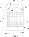
- a seating frame typically useful for an aircraft seat back is illustrated and generally designated as reference numeral 10.
- reference numeral 10 a seating frame typically useful for an aircraft seat back
- the present invention can be used to upholster a seat bottom using the same methods and components without departing from the spirit and principles of the present invention.
- the present invention can be used for all types, styles, shapes and designs of chairs, and is not restricted to use in aircraft or transportation applications.
- the seating frame 10 includes left and right vertical frame members 12 connected, in part, by upper and lower cross members 14.
- a diaphragm 100 comprising a partial open mesh fabric is installed in the seating frame 10. While seats having mesh diaphragms already exist, the present invention utilizes a novel attachment method and arrangement that uses the weave of the diaphragm 100 itself as a holding member.
- the seating frame 10 preferably includes channels 16 along the vertical frame members 12 that are used for holding the diaphragm 100 in place.
- the channels 16 are also used for the installation of the diaphragm 100.
- the path of the channels 16 in FIG. 1 is generally illustrated by the dotted lines 18.
- a cross-sectional view of a channel 16 in which an edge of the diaphragm 100 and an attachment member including a coiled element, as described in more detail below, are disposed and secured after installation, is illustrated in FIG. 7 .
- FIG. 8 provides a partial cut-away view to illustrate the channel 16 in one of the vertical frame members 12.
- the channel 16 extends along the vertical length of the seating frame 10, and, as noted, facilitates installation, removal and retention of the diaphragm 100 in a pre-tensioned state.
- the seating frame 10 is designed to have a portion at the upper part of the frame that is narrower than the main body and width of the diaphragm 100, and that acts as an area with little tension.
- This low-tension area is illustrated in FIG. 1 and designated by reference numeral 7.
- An entrance point 20 to each of the left and right channels 16 is included at the top of the low-tension area 7.
- the edge of the diaphragm 100, with an attachment member attached thereto is first engaged into the channels 16 at the low-tension area 7 and then slid along, within the channels 16, gaining or maintaining tension as the diaphragm 100 is moved beyond the low-tension are 7 into the full width section, or full-tension area 8, of the frame 10.
- the transition from the entrances 20 of the low-tension area 7 to the full-tension area 8 is gradual enough to allow the diaphragm 100 to come under increasing tension, where necessary, or to maintain a pre-tensioned condition, without becoming caught or hung up in the channels 16, or distorted or warped because of being pulled through the channels 16.
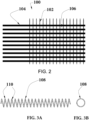
- An open mesh diaphragm comprises interwoven warp and weft yarns 102 and 104, respectively, that define open spaces or openings 106 in the diaphragm 100.
- An open mesh fabric for use as a diaphragm in accordance with the present invention preferably comprises a leno weave having coextruded elastomer monofilaments in the warp direction and high tenacity polyester yarns in the weft direction. The monofilaments are preferably thermally fused at their normal weave junctions (as is often done with coextruded monofilament yarns).
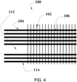
- a coil member 108 that may be used to facilitate installation and removal of a diaphragm in accordance with embodiments of the present invention is illustrated in FIGS. 3A and 3B .
- the coil member 108 comprises a series of loops 110 similar to the design of a compression spring, that are preferably wound in a spiral with a pitch and spacing that complement the spacing of the warp yarns 102 in the diaphragm 100 that will be put or held under tension.
- the coil member 108 can be a metal wire or other suitable material, such as extruded plastic.
- spring tempered 302/304 stainless steel wire is recommended.
- extruded polycarbonate can be used for such transportation applications. Both stainless steel and polycarbonate materials have the necessary physical properties and meet regulatory flammability requirement for such applications.
- the diameter of the coil member 108 can be varied, again depending on the size of the diaphragm and the amount of tension required for use once installed.
- the diameter of the coil member 108 is sized to allow each loop 110 to encompass two weft yarns 104 at their normal spacing, and/or be equal to the distance between the centers of two open spaces 106 that are separated by one warp yarn 102.
- Using such a coil member 108 greatly reduces the friction between the diaphragm 100 and the seating frame 10, allowing the diaphragm 100 to be easily slid into position even as the diaphragm 100 comes under tension or when it is already pre-tensioned, by advantageously using the combined flexibility and strength of the coil member 108.
- the coil member 108 is flexible in all directions, allowing it to conform to seating frames having contours in multiple planes, without compromising its strength.
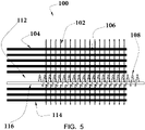
- an exemplary diaphragm 100 for use with such an attachment member in accordance with the present invention comprises interwoven warp and weft yarns 102 and 104, respectively, as described above.
- the diaphragm 100 includes an attachment zone, generally designated by reference numeral 112, where the weft yarns 104 have been omitted during weaving, and have essentially been removed.
- the warp yarns 102 still pass through the attachment zone 112, as they are used to attach the diaphragm 100 to the coil member 108.
- the spacing of the warp yarns 102 preferably is complementary to the pitch of the coil member 108.
- the portion of the diaphragm 100 between the attachment zone 110 and the edge of the diaphragm is designated hereinafter as a selvage area 114.
- the coil member 108 is positioned in the attachment zone 112, as illustrated in FIG. 5 .
- the individual loops 110 of the coil member 108 are generally positioned between warp yarns 102.
- An elongated bead member 116 is inserted lengthwise through the coil member 108 so that it is positioned between the coil member 108 and the warp yarns 102 of the diaphragm 100 in the attachment zone 112, such as illustrated in FIG. 6 .
- the bead member 116 is pinched between the diaphragm 100 and the coil member 108, as shown in FIG. 7 , and thereby aids in keeping the diaphragm 100 attached to the coil member 108 during installation, removal and use.
- the coil member 108 can then be inserted into and fed through the channel 16, such as shown in FIGS. 7 and 8 .
- the bead member 116 is generally a long cylindrical rod. It can be made of any material that is flexible to move and contort with the coil member 108 during installation and removal, but also be strong to withstand the tensions exerted by the diaphragm 100 pulling on the bead member 116 through the connection described above.
- the bead member 116 can be constructed from an extruded plastic or a light-weight metal.
- the coil member 108 can be positioned between the warp yarns 102 as shown in FIG. 9 , and when the selvage area 114 is folded along arrow A shown in FIG. 10 , each warp yarn 102 crosses over an adjacent loop 110 of the coil member 108, thereby connecting the diaphragm 100 to the coil member 108 for installation, as shown in FIG. 11 .
- the coil member 108 can then be inserted into and fed through the channel 16, such as shown in FIG. 11 .
- a diaphragm without a predefined attachment zone can be used with the coil member.
- a coil member 108 can be twisted to feed it along the length of the diaphragm 100 so that each loop 110 overlaps with at least one warp yarn 102 or at least one weft yarn 104.
- each loop 110 overlaps with one warp yarn 102 and at least one weft yarn 104.
- each loop 110 of the coil member 108 overlaps with one warp yarn 102 and two weft yarns 104.
- the selvage area 114 defined here as the area of the diaphragm 100 between the coil member 108 and the edge of the diaphragm 100, can be folded back to a position adjacent to the diaphragm 100 so that the coil member 108 can be inserted into and fed through the channel 16, such as illustrated in FIG. 13 .
- the cross-section of the weft yarns is designated with reference numeral 104.
- two weft yarns 104 are disposed inside the coil loop 110 and act to radially hold the diaphragm 100 to the coil member 108 when the selvage area 114 is folded back.
- the warp yarns 102 disposed between successive loops 110 of the coil member 108 act to axially hold the diaphragm 100 to the coil member 108, especially as the coil member 108 is being fed through the channel 16.
- each loop 110 only carries the load of just that portion of the diaphragm 100. This makes possible a lighter weight system and lowers the friction between the coil member 108 and the seating frame 10. The lower friction also allows for easier installation and removal.
- the coil member 108 is typically flexible as a result of its general design and nature, and as a result, can readily be used in contoured and curved channels with minimal risk of catching, twisting of otherwise failing. Additionally, use of the coil member 108 to facilitate installation and removal of a diaphragm in accordance with the present invention can easily accommodate high pre-tensioned diaphragms and greatly reduce the risk of warping, twisting or distorting the diaphragm during installation and removal.
- FIGS. 14-16 An attachment member that may be used to facilitate installation and removal of a diaphragm 100 in accordance with an embodiment of the present invention is illustrated in FIGS. 14-16 .
- the attachment member adds an adapter strip 120 for use with the coil member 108 previously described.
- the adapter strip 120 shown in more detail in FIG. 15 , comprises a flat web 122 having a first edge 124 with a line of perforations 126 and a second free edge 128.
- the web 122 can be constructed of any material suitable to withstand the forces to be exerted upon the adapter strip 120 to install, remove or secure a diaphragm 100, and more particularly a tensioned diaphragm in place on a seating frame 10, such as a sheet of plastic, metal, or a woven or non-woven fabric.
- the spacing of the line of perforations 126 preferably matches the pitch of the coil member 108 so as to facilitate threading of the coil member 108 through the perforations 126.
- the adapter strip 120 is used to aid in feeding the coil member 108 through the channel 16.
- the coil member 108 can be threaded through the line of perforations 126 to attach the coil member 108 and the diaphragm 100 to the adapter strip 120, as shown in FIG. 14 .
- the adapter strip 120 can be folded back next to the folded selvage area 114 to a position adjacent to, and preferably flush with the diaphragm 100, as shown in FIG. 16 .
- the coil member 108 can be inserted into the channel 16 in the seating frame 10 and fed through the channel 16 with the assistance of pulling on the second free edge 128 of the adapter strip 120.
- the adapter strip 120 is used instead of the channel 16 in the seating frame 10. That is, an adapter strip 120, much as described above, can be secured to the vertical members 12 of the seating frame 10, as shown in FIG. 17 .
- the coil member 108 can be threaded through the line of perforations 126 in the adapter strip 120 to feed the diaphragm 100 along the adapter strip 120, thereby attaching the diaphragm 100 to the seating frame 10.
- the coil member 108 can be threaded into the diaphragm 100 and the line of perforations 126 simultaneously. To remove the diaphragm 100 from the seating frame 10, the coil member 108 can simply be unthreaded from the line of perforations 126.
- FIG. 18 illustrates use of the adapter strip in this manner to receive the diaphragm 100 as connected to the coil member 108 using the assembly shown in FIGS. 5-7 and described above.
- connection of the diaphragm 100 to the coil member 108 is stronger when intertwined at a distance from the edge of the diaphragm 100 than if the coil member 108 were connected right at the edge.
- the specific location of the coil member 108 from the edge of the diaphragm 100 - and thus both the position of the attachment zone 112, if used, and the length of the selvage area 114 - is generally determined by the size of the diaphragm 100 and the amount of stretch that will be needed in the installed diaphragm.
- the selvage area 114 can be folded over and against the diaphragm 100 to hide it after installation.
- FIGS. 19-21 an alternate embodiment for installation and removal of a diaphragm to a seating frame is illustrated.
- An open mesh diaphragm 100 generally comprising interwoven warp and weft yarns 102 and 104, respectively, is provided with an attachment member 105 for installation of the diaphragm 100 in a seating frame 10 having channels 16 adapted to receive a portion of the diaphragm 100, as shown in FIG. 20 .
- the attachment member 105 comprises an adapter strip 130 and a coil member 108, as shown in FIG. 19 .
- the coil member 108 is adapted to be intertwined with the weave of the diaphragm 100 and thereafter inserted into and held by a channel 16 in the seating frame 10, as shown in FIG. 21 .
- the adapter strip 130 comprises a web 132 having an open loop fringe on a first edge 134 thereof and a free second edge 136, whereby the coil member 108 is fed through the open loops 138 of the adapter strip 130 to secure said adapter strip 130 to the coil member 108.
- the coil member 108 is simultaneously fed through the open loops 138 of the adapter strip 130 and the weave openings 106 of the diaphragm 100, as shown in FIG. 20 .
- the spacing of the open loops 138 on the adapter strip 130 is generally the same as the pitch of the coil member 108.
- this spacing is also generally the same as the spacing of the warp yarns 102 and the openings 106 of the diaphragm 100.
- the relative spacing for the diaphragm mesh, the coil member 108 and the open loops 138 of the adapter strip 130 are shown in FIG. 20 .
- the adapter strip 130 is folded toward the diaphragm 100, capturing a selvage area 114 of the diaphragm 100 therebetween, as shown in FIG. 21 . Thereafter, the coil member 108 can be fed into and through the channel 16 of the seating frame 10 by pulling on the free second edge 136 of the adapter strip 130. Once the coil member 108 is fully fed into through the channel 16, the adapter strip 130 can be left adjacent to and preferably flush with the diaphragm 100. In this regard, the adapter strip 130 provides added strength to the diaphragm 100 along its vertical edges.
- the adapter strip 130 can be constructed from any material, including but not limited to a plastic or polymeric web, a metal sheet, such as aluminum, or a woven or non-woven fabric or tape.
- the adapter strip 130 can comprise a support tape woven from yarns of a strong, high tenacity fiber, preferably a para-aramid such as DuPont Kevlar.
- the web may be woven to form the short loop fringe along the first edge 134, where the loops 138 are spaced to align with the openings 106 of the diaphragm 100.
- the adapter strip 130 essentially provides a pulling strap that can be used to pull the attachment assembly through the channel 16 during installation.
- the adapter strip 130 can experience a considerable load from friction between a tightly tensioned diaphragm 100 and the channel 16. This makes a strong adapter strip 130 generally beneficial for carrying the total load resulting from the full length of the diaphragm 100.
- each fringe loop 138 of the adapter strip 130 only carries the load of moving just that portion of the entire assembly.
- the diaphragm need not be a woven open mesh fabric.
- an attachment arrangement is provided that allows the present invention to be applied to closed fabric weaves, films, or closed elastomeric fabrics (collectively referred to hereinafter as "closed fabric diaphragm").
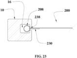
- closed fabric diaphragm a closed fabric diaphragm 200 is provided with an attachment member 205 for installation of the diaphragm 200 in a seating frame 10 having channels 16 adapted to receive a portion of the attachment member 205 to hold the diaphragm 200 in place relative to the seating frame 10. Similar to the embodiment illustrated in FIGS.
- the attachment member 205 comprises an adapter strip 230 and a coil member 208.
- the adapter strip 230 constructed similar to the strip 130 shown in FIG. 20 , joins the diaphragm 200 to the coil member 208.
- the adapter strip 230 comprises a web 232 having an open loop fringe on a first edge 234 thereof and a second edge 236 that is secured to the diaphragm 200 so that the open loops 238 project away from the diaphragm 200.
- the adapter strip 230 can be sewn with stitches 240 to the closed fabric diaphragm 200.
- the coil member 208 is threaded through the open loops 238 and thereafter fed through the channel 16 to install the diaphragm 200 to the seating frame 10, as shown in FIG. 23 .
- the adapter strip 230 can be pulled to aid in feeding the coil member 208 through the channel 16 much in the same manner as described above for other embodiments.
- the adapter strip 230 can be used to draw the coil member 208 out of the channel 16 when removing the diaphragm 200.
- the spacing of the open loops 238 on the adapter strip 200 is generally the same as the pitch of the coil member 208. This facilitates threading of the coil member 208 through the open loop fringe of the adapter strip 230.
- the relative spacing for the diaphragm mesh, the coil member 208 and the open loops 238 of the adapter strip 230 are shown in FIG. 22 .
- the replacement diaphragm 300 is preferably supplied as a pre-tensioned open mesh fabric, similar to the diaphragm 100 shown in FIG. 2 , held in a stretched condition by a novel retainer sheet 310, illustrated in FIGS. 24 and 25 .
- the retainer sheet 310 comprises a flexible sheet of material acting as a filler to keep the open spaces 306 in the stretched open weave fabric from closing to their normal non-stretched size and condition.
- the retainer sheet 310 includes a plurality of projections 312 covering a first face 314 of a base membrane 316 and extending normally therefrom for insertion into and through the open spaces 306 of the diaphragm 300 during use.
- the projections 312 have a size and shape designed to complement the size and shape of the openings 306 in the mesh after it has been stretched to the desired dimensions needed for installation into the seating frame.
- FIG. 25 illustrates the insertion of the projections 312 into and through the openings 306 of the diaphragm 300.
- the projections 312 are preferably inserted far enough so that the base membrane 316 of the retainer sheet 310 is adjacent to and, more preferably, flush with the diaphragm 300.
- the retainer sheet 310 need not be thick or strong.
- the retainer sheet 310 does not hold the tension of the stretched fabric. It only holds the projections 312 in place within the openings 306 while the projections 312 resist the load of the contacting fabric.
- the retainer sheet 310 does, however, need to be strong enough to withstand the pulling required to extract the projections 312 from the mesh openings 306 in the diaphragm 300 once the diaphragm 300 has been installed in a seating frame 10. This load, however, is not very high, because only a small portion of the retainer sheet 310 needs to be removed at a time.
- the retainer sheet 310 is preferably removed by a peeling action. It is intended for the retainer sheet 310 to be reusable, and thus it must have sufficient rigidity and strength to withstand multiple uses, while not compromising its flexibility for installation, removal, and use, as desired.
- the retainer sheet 310 is constructed in several ways as to suit a particular mesh fabric depending on weave and varying requirement, such as cost and sustainability.
- One way to construct the retainer sheet 310 is to thermoform a plastic sheet with heated forming rollers or vacuum/pressure forming dies.
- Another way is by compression molding plastic compounds with matched pressure molds. This latter method is also suitable for biodegradable materials such as organic pulps combined with biopolymer resins.
- a woven fabric backer can be integrally molded or laminated to the smooth second face 318 of the retainer membrane 316 - that is opposite to the first face 314 from which the projections 312 extend - which backer provides added stability, rigidity, sustainability, and strength, permitting the retainer sheet to withstand multiple uses while holding up to the tensions exerted on the retainer sheet and projections.
- a backer sheet does not compromise the flexibility that permits the retainer sheet to be removed from a diaphragm after installation by a peeling action.
- a pre-tensioned diaphragm 300 is first constructed by stretching the diaphragm 300 to create the desired tension.
- the retainer sheet 310 is installed to the mesh diaphragm 300 by pressing it onto the surface of the diaphragm 300 while forcing the projections 312 into and through the openings 306 between the warp and weft yarns 302 and 304, respectively, of the mesh fabric.
- the projections 312 are inserted through the openings 306 and the retainer sheet 310 is pressed against the diaphragm 300 so that the base membrane 316 of the retainer sheet 310 is adjacent to and, more preferably, flush with the diaphragm 300.
- the retainer sheet 310 can also be installed by pressing the stretched diaphragm 300 onto the protrusions 312 using a roller with a resilient cover.
- the projections 312 prevent the openings 306 from returning to their free-state size and condition, since the projections 312 are relatively incompressible and resist the contraction of the tensioned warp and weft yarns 302 and 304. Therefore, the tensioned yarns 302, 304 and openings 306 cannot contract, and thus, the diaphragm 300 is held in its pre-tensioned, stretched condition until the retainer sheet 310 is removed, as described above.
- the retainer sheet 310 provides an optimal combination of strength - in order to resist contraction of the diaphragm 300 from its tensioned condition - and flexibility - in order to permit manipulation of the stretched diaphragm 300 to feed it through the seating frame 10 during installation. For example, when the retainer sheet 310 is attached to the diaphragm 300, the combined diaphragm 300 and retainer sheet 310 can still be twisted, bent or otherwise manipulated while maintaining the tension of the diaphragm 300. This allows installation of the pre-tensioned diaphragm 300 onto contoured frames as is desirable in transportation applications.
Landscapes
- Engineering & Computer Science (AREA)
- Aviation & Aerospace Engineering (AREA)
- Transportation (AREA)
- Mechanical Engineering (AREA)
- Woven Fabrics (AREA)
- Diaphragms And Bellows (AREA)
Claims (14)
- Eine Anordnung zum Polstern eines Sitzes mit einem Sitzrahmen (10), wobei die Anordnung umfasst:einem Membran (100) undein Befestigungselement zum Befestigen der Membran an dem Sitzrahmen (10), wobei das Befestigungselement ein Spiralelement (108, 208) umfasst,wobei die Anordnung dadurch gekennzeichnet ist, dass:die Anordnung ferner einen Adapterstreifen (120, 130, 230) mit einer Kante (124, 134) umfasst, wobei der Adapterstreifen entweder eine sich entlang der Kante erstreckende Perforationslinie (126) oder eine Vielzahl von offenen Schleifen (138, 238) aufweist, die von der Kante vorstehen, unddas Spiralelement (108, 208) so ausgestaltet ist, dass es sich in einer Ebene der Membran (100) erstreckt, und ferner so ausgestaltet ist, dass es durch die Perforationslinie oder die mehreren offenen Schleifen (138, 238) des Adapterstreifens gefädelt werden kann.
- Die Anordnung nach Anspruch 1, wobei der Adapterstreifen die sich entlang der Kante erstreckende Perforationslinie aufweist, wodurch das Spiralelement (108, 208) so ausgestaltet ist, dass es im Gebrauch durch die Perforationslinie zur Installation der Membran (100) am Sitzrahmen gefädelt werden kann.
- Die Anordnung nach Anspruch 1, wobei der Adapterstreifen einen Teil des Befestigungselements bildet und so ausgestaltet ist, dass er mit dem Spiralelement (108, 208) verbunden werden kann, um die Installation der Membran (100) am Sitzrahmen (10) im Gebrauch zu unterstützen.
- Die Anordnung nach Anspruch 3, wobei der Adapterstreifen (120, 130, 230) die Vielzahl offener Schleifen (138, 238) enthält, wodurch der Adapterstreifen so ausgestaltet ist, dass er mit dem Spiralelement (108, 208) verbunden werden kann, indem das Spiralelement im Gebrauch durch die Vielzahl offener Schleifen gefädelt wird.
- Die Anordnung nach Anspruch 4, wobei die Membran (100) ein offen gewebtes Material ist, das verwobene Kett- und Schussfäden umfasst, und wobei ferner jede Schlaufe des Spiralelements (108, 208) so eingefädelt werden kann, dass sie sich mit mindestens einem Kettfaden und einem Schussfaden überlappt, um die Membran (100) mit dem Spiralelement zu verbinden.
- Die Anordnung nach Anspruch 3, wobei die Membran (100) ein geschlossen gewebtes Material ist, die Kante des Adapterstreifens eine erste Kante ist und der Adapterstreifen (120, 130, 230) ferner eine zweite Kante gegenüber der ersten Kante aufweist, die an der Membran befestigt ist, so dass die offenen Schlaufen (138, 238) von der Membran weg nach außen ragen, so dass das Spiralelement (108, 208) durch die Vielzahl der offenen Schlaufen gefädelt werden kann, um das Spiralelement mit der Membran (100) mittels des Adapterstreifens zu verbinden.
- Die Anordnung nach Anspruch 1, wobei die Membran (100) ein offen gewebtes Material ist, das verwobene Kett- und Schussfäden umfasst, die zwischen sich Öffnungen bilden, und die Anordnung ferner umfasst:eine Haltefolie zum Aufrechterhalten der Spannung in der Membran (100), wobei die Haltefolie eine Basismembran mit einer ersten Fläche umfasst, von der sich eine Vielzahl von Vorsprüngen erstreckt, wobei jeder der Vorsprünge eine Querschnittsgröße und -form aufweist, die zu den Öffnungen in der Membran (100) zwischen den Kett- und Schussfäden komplementär sind, wodurch das Einsetzen der Vorsprünge der Haltefolie in die Öffnungen die gespannte Abmessung der Öffnungen während der Installation der Membran an dem Sitzrahmen (10) aufrechterhält.
- Die Anordnung nach Anspruch 1, wobei die Membran (100) eine offen gewebte Membran ist, die verwobene Kett- und Schussfäden umfasst und eine Befestigungszone in der Nähe einer ersten Kante der Membran (100) und einen Webkantenbereich definiert, der zwischen der Befestigungszone und der Kante der Membran definiert ist, wobei die Befestigungszone keine Schussfäden aufweist; und
wobei ferner das Befestigungselement ein längliches Wulstelement umfasst, wobei das Spiralelement (108, 208) mit der Membran (100) verbunden ist, indem das Wulstelement innerhalb des Spiralelements zwischen den Schlaufen des Spiralelements und den Kettfäden in der Befestigungszone der Membran axial positioniert wird, so dass, wenn der Kantenbereich der Membran von dem Spiralelement weggefaltet wird, das Wulstelement zwischen den Schlaufen des Spiralelements und den Kettfäden eingeklemmt wird, um die Membran (100) an dem Spiralelement zu befestigen. - Ein Verfahren zum Polstern eines Sitzrahmens (10) mit mindestens einem darin ausgebildeten Kanal, wobei das Verfahren umfasst:Bereitstellung einer Membran (100);Anbringen eines Befestigungselements an der Membran, wobei das Befestigungselement ein Spiralelement (108, 208) umfasst; undVorschieben mindestens des Spiralelement durch den mindestens einen Kanal, bis sich die Membran (100) in einer gewünschten Position relativ zum Sitzrahmen (10) befindet,wobei,die Anordnung ferner einen Adapterstreifen (120, 130, 230) mit einer Kante (124, 134) umfasst, wobei der Adapterstreifen entweder eine sich entlang der Kante erstreckende Perforationslinie (126) oder eine Vielzahl von offenen Schleifen (138, 238) aufweist, die von der Kante vorstehen,das Spiralelement (108, 208) so ausgestaltet ist, dass es sich in einer Ebene der Membran (100) erstreckt, und ferner so ausgestaltet ist, dass es durch die Perforationslinie oder die mehreren offenen Schleifen (138, 238) des Adapterstreifens gefädelt werden kann, unddas Verfahren ferner das Einfädeln des Spiralelements durch die Perforationslinie oder die mehreren offenen Schleifen (138, 238) des Adapterstreifens umfasst, um das Vorschieben des Spiralelements durch den mindestens einen Kanal zu unterstützen.
- Das Verfahren nach Anspruch 9, wobei die Membran (100) verwobene Kett- und Schussfäden umfasst und das Spiralelement (108, 208) an der Membran befestigt wird, indem das Spiralelement so durch das Membrangewebe gefädelt wird, dass jede Schlaufe des Spiralelements mindestens einen Kettfaden oder mindestens einen Schussfaden überlappt.
- Das Verfahren nach Anspruch 9, das ferner den Schritt des Ziehens des Adapterstreifens (120, 130, 230) umfasst, um das Vorschieben des Spiralelements (108, 208) durch den mindestens einen Kanal zu unterstützen.
- Das Verfahren nach Anspruch 9, wobei der Adapterstreifen (120, 130, 230) die mehreren offenen Schleifen (138, 238) umfasst und der Adapterstreifen mit dem Spiralelement (108, 208) verbunden wird, indem das Spiralelement durch die mehreren offenen Schleifen gefädelt wird.
- Das Verfahren nach Anspruch 9, wobei der Adapterstreifen (120) einen Steg (122) mit der Perforationslinie an einem Rand desselben umfasst, wobei das Spiralelement (108) durch die Perforationslinie gefädelt wird, um das Spiralelement (108) an dem Adapterstreifen zu befestigen.
- Das Verfahren nach Anspruch 9, wobei die Membran (100) eine geschlossen gewebte Membran ist, an der der Adapterstreifen (130) entlang einer Kante befestigt ist, wobei die Kante des Adapterstreifens mit der Vielzahl von offenen Schleifen (138) versehen ist, die von der Membran nach außen vorstehen,
wobei das Spiralelement (108) an der Membran (100) befestigt wird, indem das Spiralelement durch die Vielzahl von offenen Schleifen gefädelt wird.
Priority Applications (1)
| Application Number | Priority Date | Filing Date | Title |
|---|---|---|---|
| EP21197798.8A EP3949807B1 (de) | 2016-03-31 | 2017-03-31 | Methode um ein sitzmembran auf einem sitzrahmen zu installieren |
Applications Claiming Priority (2)
| Application Number | Priority Date | Filing Date | Title |
|---|---|---|---|
| US201662315900P | 2016-03-31 | 2016-03-31 | |
| PCT/US2017/025368 WO2017173265A1 (en) | 2016-03-31 | 2017-03-31 | Seating suspension diaphragm having integrated slide-in attachment means |
Related Child Applications (2)
| Application Number | Title | Priority Date | Filing Date |
|---|---|---|---|
| EP21197798.8A Division EP3949807B1 (de) | 2016-03-31 | 2017-03-31 | Methode um ein sitzmembran auf einem sitzrahmen zu installieren |
| EP21197798.8A Division-Into EP3949807B1 (de) | 2016-03-31 | 2017-03-31 | Methode um ein sitzmembran auf einem sitzrahmen zu installieren |
Publications (3)
| Publication Number | Publication Date |
|---|---|
| EP3416525A1 EP3416525A1 (de) | 2018-12-26 |
| EP3416525A4 EP3416525A4 (de) | 2019-10-30 |
| EP3416525B1 true EP3416525B1 (de) | 2023-03-01 |
Family
ID=59958565
Family Applications (2)
| Application Number | Title | Priority Date | Filing Date |
|---|---|---|---|
| EP17776772.0A Active EP3416525B1 (de) | 2016-03-31 | 2017-03-31 | Sitzende aufhängungsmembran mit integriertem gleitbefestigungsmittel |
| EP21197798.8A Active EP3949807B1 (de) | 2016-03-31 | 2017-03-31 | Methode um ein sitzmembran auf einem sitzrahmen zu installieren |
Family Applications After (1)
| Application Number | Title | Priority Date | Filing Date |
|---|---|---|---|
| EP21197798.8A Active EP3949807B1 (de) | 2016-03-31 | 2017-03-31 | Methode um ein sitzmembran auf einem sitzrahmen zu installieren |
Country Status (3)
| Country | Link |
|---|---|
| US (2) | US11753171B2 (de) |
| EP (2) | EP3416525B1 (de) |
| WO (2) | WO2017173265A1 (de) |
Families Citing this family (18)
| Publication number | Priority date | Publication date | Assignee | Title |
|---|---|---|---|---|
| JP6339296B2 (ja) * | 2014-12-31 | 2018-06-06 | シンガポール・テクノロジーズ・エアロスペース・リミテッドSingapore Technologies Aerospace Ltd | シートサスペンションの設置方法及び乗客用シート |
| CN113165560B (zh) * | 2018-08-03 | 2024-01-19 | 伊利诺斯工具制品有限公司 | 座椅和制造座椅的方法 |
| WO2020028679A1 (en) * | 2018-08-03 | 2020-02-06 | Illinois Tool Works Inc. | Load bearing surface with kinetic energy management fabric |
| US10669030B1 (en) * | 2019-04-23 | 2020-06-02 | B/E Aerospace, Inc. | Seat pan diaphragm |
| US11584273B2 (en) * | 2019-08-28 | 2023-02-21 | Lear Corporation | Trim assembly ornamental stitching |
| US11203434B2 (en) | 2019-10-28 | 2021-12-21 | B/E Aersospace, Inc. | Diaphragm attachment method for aircraft seating |
| JP7686582B2 (ja) * | 2022-01-14 | 2025-06-02 | 株式会社タチエス | 車両用シート |
| US12522362B2 (en) | 2022-03-17 | 2026-01-13 | B/E Aerospace, Inc. | Hybrid bottom seat cushion |
| US11827363B2 (en) | 2022-03-17 | 2023-11-28 | B/E Aerospace, Inc. | Composite seat bottom diaphragm |
| US11845557B2 (en) | 2022-03-29 | 2023-12-19 | B/E Aerospace, Inc. | Springless dress cover and lower closeout system for passenger seat |
| US11731766B1 (en) | 2022-03-29 | 2023-08-22 | B/E Aerospace, Inc. | Wedged clamping device and method for aircraft seat frame |
| USD1083415S1 (en) | 2022-03-29 | 2025-07-15 | B/E Aerospace, Inc. | Economy class passenger seat |
| US12326742B2 (en) | 2022-12-22 | 2025-06-10 | Lear Corporation | Valve and actuator assembly for a fluid system in a vehicle seat assembly |
| DK181559B1 (en) * | 2022-06-28 | 2024-05-15 | Lear Corp | METHOD AND MACHINE FOR ATTACHING A SEAT COVER TO WELDED POLYMER FIBERS WITH A SPIRAL WRAPPED ADJUSTMENT ATTACHMENT CONNECTOR AND APPARATUS |
| KR20250037754A (ko) * | 2022-06-16 | 2025-03-18 | 리어 코포레이션 | 차량 좌석 조립체 및 그 하위조립체 |
| US12337738B2 (en) | 2022-11-09 | 2025-06-24 | Lear Corporation | Fluid system for a vehicle seat assembly |
| CN115890234B (zh) * | 2022-12-18 | 2026-02-06 | 贵州华昌汽车电器有限公司 | 一种汽车门锁锁芯装配锁片锁簧的装置 |
| US12434844B2 (en) | 2023-03-21 | 2025-10-07 | B/E Aerospace, Inc. | Shape memory polymer integrated cushion upholstery using artificial muscles technology |
Family Cites Families (13)
| Publication number | Priority date | Publication date | Assignee | Title |
|---|---|---|---|---|
| US2673599A (en) * | 1948-03-12 | 1954-03-30 | Heywood Wakefield Co | Spring filled cushion |
| NL74633C (de) * | 1949-03-31 | 1954-04-16 | ||
| GB680906A (en) | 1949-08-26 | 1952-10-15 | Kenneth William Bradshaw | Improvements relating to means for securing flexible sheet material and to articles of furniture embodying such means |
| US2839126A (en) * | 1953-12-14 | 1958-06-17 | Ralph A O'neill | Attachment of webbing strip or the like, and novel frame support and attaching means |
| GB902277A (en) * | 1961-04-14 | 1962-08-01 | Barker & Rone Ltd | Wire assemblies primarily for use in ventilated cushions |
| US3420278A (en) * | 1965-08-03 | 1969-01-07 | Heckethorn Mfg | Method of making woven metallic web structures |
| US6254190B1 (en) | 1999-09-29 | 2001-07-03 | Peter G. G. Gregory | Chair having a seat with differential front and rear support portions |
| US20030001424A1 (en) * | 2001-06-27 | 2003-01-02 | David Mundell | Integral elastomeric suspension article and manufacturing process |
| US6983997B2 (en) * | 2001-06-29 | 2006-01-10 | Haworth, Inc. | Chair having a suspension seat assembly |
| JP2004229957A (ja) * | 2003-01-31 | 2004-08-19 | Delta Tooling Co Ltd | 座席構造 |
| GB2420705A (en) | 2006-01-25 | 2006-06-07 | Armon Ltd | Child's high chair |
| PL2538820T3 (pl) * | 2010-02-26 | 2014-07-31 | Donati Spa | Urządzenie do synchronizacji siedziska i oparcia krzesła |
| EP2487283A1 (de) | 2011-02-10 | 2012-08-15 | Gessner Holding AG | Textilsubstrat mit wasser- und wasserdampfableitenden Eigenschaften |
-
2017
- 2017-03-31 EP EP17776772.0A patent/EP3416525B1/de active Active
- 2017-03-31 US US15/475,824 patent/US11753171B2/en active Active
- 2017-03-31 WO PCT/US2017/025368 patent/WO2017173265A1/en not_active Ceased
- 2017-03-31 EP EP21197798.8A patent/EP3949807B1/de active Active
- 2017-07-21 US US15/656,161 patent/US10518886B2/en active Active
-
2018
- 2018-07-20 WO PCT/US2018/042991 patent/WO2019018711A1/en not_active Ceased
Also Published As
| Publication number | Publication date |
|---|---|
| EP3949807A1 (de) | 2022-02-09 |
| EP3416525A4 (de) | 2019-10-30 |
| US20170320579A1 (en) | 2017-11-09 |
| US20170283071A1 (en) | 2017-10-05 |
| WO2017173265A1 (en) | 2017-10-05 |
| EP3416525A1 (de) | 2018-12-26 |
| WO2019018711A1 (en) | 2019-01-24 |
| EP3949807B1 (de) | 2023-09-06 |
| US11753171B2 (en) | 2023-09-12 |
| US10518886B2 (en) | 2019-12-31 |
Similar Documents
| Publication | Publication Date | Title |
|---|---|---|
| EP3416525B1 (de) | Sitzende aufhängungsmembran mit integriertem gleitbefestigungsmittel | |
| US6966606B2 (en) | Carrier and attachment method for load bearing fabric | |
| EP2991898B1 (de) | Flugzeugsitzlehnenanordnung | |
| US7458642B1 (en) | Sling chair construction having non-weight bearing material and method of constructing same | |
| IT201900011508A1 (it) | Tessuto per seggiola componibile | |
| US20150284093A1 (en) | Lightweight upholstery cover with edge attachment | |
| IT201800010836A1 (it) | Seggiola componibile | |
| JP5525025B2 (ja) | 締縛用コードアセンブリ及びその取付方法 | |
| US9579999B2 (en) | Lightweight headrest assembly | |
| US11097640B2 (en) | Method and articles for attaching upholstery covers and other flexible material | |
| EP3362358B1 (de) | Passagiersitz einschliesslich eines rückennetz | |
| KR101253526B1 (ko) | 블라인드 커튼 기능을 가지는 롤 커튼용 커튼지 및 그 제조방법 | |
| EP3126187B1 (de) | Leichte kopfstützenanordnung | |
| US3058125A (en) | Ventilating and shock absorbing cushion | |
| IT202000016399A1 (it) | Seggiola componibile e metodo di realizzazione di detta seggiola componibile | |
| KR101383071B1 (ko) | 차량용 커텐장치 | |
| CN120643012A (zh) | 一种防起拱布带及其尼龙拉链和加工工艺 | |
| US655253A (en) | Woven-wire fabric. | |
| IT201900007761A1 (it) | Inserto per seggiola componibile |
Legal Events
| Date | Code | Title | Description |
|---|---|---|---|
| STAA | Information on the status of an ep patent application or granted ep patent |
Free format text: STATUS: THE INTERNATIONAL PUBLICATION HAS BEEN MADE |
|
| PUAI | Public reference made under article 153(3) epc to a published international application that has entered the european phase |
Free format text: ORIGINAL CODE: 0009012 |
|
| STAA | Information on the status of an ep patent application or granted ep patent |
Free format text: STATUS: REQUEST FOR EXAMINATION WAS MADE |
|
| 17P | Request for examination filed |
Effective date: 20180921 |
|
| AK | Designated contracting states |
Kind code of ref document: A1 Designated state(s): AL AT BE BG CH CY CZ DE DK EE ES FI FR GB GR HR HU IE IS IT LI LT LU LV MC MK MT NL NO PL PT RO RS SE SI SK SM TR |
|
| AX | Request for extension of the european patent |
Extension state: BA ME |
|
| DAV | Request for validation of the european patent (deleted) | ||
| DAX | Request for extension of the european patent (deleted) | ||
| A4 | Supplementary search report drawn up and despatched |
Effective date: 20190926 |
|
| RIC1 | Information provided on ipc code assigned before grant |
Ipc: F16B 12/42 20060101ALI20190920BHEP Ipc: A47C 4/30 20060101AFI20190920BHEP Ipc: B64D 11/06 20060101ALI20190920BHEP Ipc: B60N 2/70 20060101ALI20190920BHEP Ipc: A47C 5/02 20060101ALI20190920BHEP |
|
| STAA | Information on the status of an ep patent application or granted ep patent |
Free format text: STATUS: EXAMINATION IS IN PROGRESS |
|
| 17Q | First examination report despatched |
Effective date: 20200921 |
|
| GRAP | Despatch of communication of intention to grant a patent |
Free format text: ORIGINAL CODE: EPIDOSNIGR1 |
|
| STAA | Information on the status of an ep patent application or granted ep patent |
Free format text: STATUS: GRANT OF PATENT IS INTENDED |
|
| INTG | Intention to grant announced |
Effective date: 20221005 |
|
| GRAS | Grant fee paid |
Free format text: ORIGINAL CODE: EPIDOSNIGR3 |
|
| GRAA | (expected) grant |
Free format text: ORIGINAL CODE: 0009210 |
|
| STAA | Information on the status of an ep patent application or granted ep patent |
Free format text: STATUS: THE PATENT HAS BEEN GRANTED |
|
| AK | Designated contracting states |
Kind code of ref document: B1 Designated state(s): AL AT BE BG CH CY CZ DE DK EE ES FI FR GB GR HR HU IE IS IT LI LT LU LV MC MK MT NL NO PL PT RO RS SE SI SK SM TR |
|
| REG | Reference to a national code |
Ref country code: GB Ref legal event code: FG4D |
|
| REG | Reference to a national code |
Ref country code: CH Ref legal event code: EP Ref country code: AT Ref legal event code: REF Ref document number: 1550419 Country of ref document: AT Kind code of ref document: T Effective date: 20230315 |
|
| REG | Reference to a national code |
Ref country code: DE Ref legal event code: R096 Ref document number: 602017066434 Country of ref document: DE |
|
| REG | Reference to a national code |
Ref country code: IE Ref legal event code: FG4D |
|
| REG | Reference to a national code |
Ref country code: LT Ref legal event code: MG9D |
|
| REG | Reference to a national code |
Ref country code: NL Ref legal event code: MP Effective date: 20230301 |
|
| PG25 | Lapsed in a contracting state [announced via postgrant information from national office to epo] |
Ref country code: RS Free format text: LAPSE BECAUSE OF FAILURE TO SUBMIT A TRANSLATION OF THE DESCRIPTION OR TO PAY THE FEE WITHIN THE PRESCRIBED TIME-LIMIT Effective date: 20230301 Ref country code: NO Free format text: LAPSE BECAUSE OF FAILURE TO SUBMIT A TRANSLATION OF THE DESCRIPTION OR TO PAY THE FEE WITHIN THE PRESCRIBED TIME-LIMIT Effective date: 20230601 Ref country code: LV Free format text: LAPSE BECAUSE OF FAILURE TO SUBMIT A TRANSLATION OF THE DESCRIPTION OR TO PAY THE FEE WITHIN THE PRESCRIBED TIME-LIMIT Effective date: 20230301 Ref country code: LT Free format text: LAPSE BECAUSE OF FAILURE TO SUBMIT A TRANSLATION OF THE DESCRIPTION OR TO PAY THE FEE WITHIN THE PRESCRIBED TIME-LIMIT Effective date: 20230301 Ref country code: HR Free format text: LAPSE BECAUSE OF FAILURE TO SUBMIT A TRANSLATION OF THE DESCRIPTION OR TO PAY THE FEE WITHIN THE PRESCRIBED TIME-LIMIT Effective date: 20230301 Ref country code: ES Free format text: LAPSE BECAUSE OF FAILURE TO SUBMIT A TRANSLATION OF THE DESCRIPTION OR TO PAY THE FEE WITHIN THE PRESCRIBED TIME-LIMIT Effective date: 20230301 |
|
| REG | Reference to a national code |
Ref country code: AT Ref legal event code: MK05 Ref document number: 1550419 Country of ref document: AT Kind code of ref document: T Effective date: 20230301 |
|
| PG25 | Lapsed in a contracting state [announced via postgrant information from national office to epo] |
Ref country code: SE Free format text: LAPSE BECAUSE OF FAILURE TO SUBMIT A TRANSLATION OF THE DESCRIPTION OR TO PAY THE FEE WITHIN THE PRESCRIBED TIME-LIMIT Effective date: 20230301 Ref country code: PL Free format text: LAPSE BECAUSE OF FAILURE TO SUBMIT A TRANSLATION OF THE DESCRIPTION OR TO PAY THE FEE WITHIN THE PRESCRIBED TIME-LIMIT Effective date: 20230301 Ref country code: NL Free format text: LAPSE BECAUSE OF FAILURE TO SUBMIT A TRANSLATION OF THE DESCRIPTION OR TO PAY THE FEE WITHIN THE PRESCRIBED TIME-LIMIT Effective date: 20230301 Ref country code: GR Free format text: LAPSE BECAUSE OF FAILURE TO SUBMIT A TRANSLATION OF THE DESCRIPTION OR TO PAY THE FEE WITHIN THE PRESCRIBED TIME-LIMIT Effective date: 20230602 Ref country code: FI Free format text: LAPSE BECAUSE OF FAILURE TO SUBMIT A TRANSLATION OF THE DESCRIPTION OR TO PAY THE FEE WITHIN THE PRESCRIBED TIME-LIMIT Effective date: 20230301 |
|
| PG25 | Lapsed in a contracting state [announced via postgrant information from national office to epo] |
Ref country code: SM Free format text: LAPSE BECAUSE OF FAILURE TO SUBMIT A TRANSLATION OF THE DESCRIPTION OR TO PAY THE FEE WITHIN THE PRESCRIBED TIME-LIMIT Effective date: 20230301 Ref country code: RO Free format text: LAPSE BECAUSE OF FAILURE TO SUBMIT A TRANSLATION OF THE DESCRIPTION OR TO PAY THE FEE WITHIN THE PRESCRIBED TIME-LIMIT Effective date: 20230301 Ref country code: PT Free format text: LAPSE BECAUSE OF FAILURE TO SUBMIT A TRANSLATION OF THE DESCRIPTION OR TO PAY THE FEE WITHIN THE PRESCRIBED TIME-LIMIT Effective date: 20230703 Ref country code: EE Free format text: LAPSE BECAUSE OF FAILURE TO SUBMIT A TRANSLATION OF THE DESCRIPTION OR TO PAY THE FEE WITHIN THE PRESCRIBED TIME-LIMIT Effective date: 20230301 Ref country code: CZ Free format text: LAPSE BECAUSE OF FAILURE TO SUBMIT A TRANSLATION OF THE DESCRIPTION OR TO PAY THE FEE WITHIN THE PRESCRIBED TIME-LIMIT Effective date: 20230301 Ref country code: AT Free format text: LAPSE BECAUSE OF FAILURE TO SUBMIT A TRANSLATION OF THE DESCRIPTION OR TO PAY THE FEE WITHIN THE PRESCRIBED TIME-LIMIT Effective date: 20230301 |
|
| REG | Reference to a national code |
Ref country code: CH Ref legal event code: PL |
|
| PG25 | Lapsed in a contracting state [announced via postgrant information from national office to epo] |
Ref country code: SK Free format text: LAPSE BECAUSE OF FAILURE TO SUBMIT A TRANSLATION OF THE DESCRIPTION OR TO PAY THE FEE WITHIN THE PRESCRIBED TIME-LIMIT Effective date: 20230301 Ref country code: IS Free format text: LAPSE BECAUSE OF FAILURE TO SUBMIT A TRANSLATION OF THE DESCRIPTION OR TO PAY THE FEE WITHIN THE PRESCRIBED TIME-LIMIT Effective date: 20230701 |
|
| REG | Reference to a national code |
Ref country code: BE Ref legal event code: MM Effective date: 20230331 |
|
| REG | Reference to a national code |
Ref country code: DE Ref legal event code: R097 Ref document number: 602017066434 Country of ref document: DE |
|
| PG25 | Lapsed in a contracting state [announced via postgrant information from national office to epo] |
Ref country code: LU Free format text: LAPSE BECAUSE OF NON-PAYMENT OF DUE FEES Effective date: 20230331 |
|
| PLBE | No opposition filed within time limit |
Free format text: ORIGINAL CODE: 0009261 |
|
| STAA | Information on the status of an ep patent application or granted ep patent |
Free format text: STATUS: NO OPPOSITION FILED WITHIN TIME LIMIT |
|
| PG25 | Lapsed in a contracting state [announced via postgrant information from national office to epo] |
Ref country code: MC Free format text: LAPSE BECAUSE OF FAILURE TO SUBMIT A TRANSLATION OF THE DESCRIPTION OR TO PAY THE FEE WITHIN THE PRESCRIBED TIME-LIMIT Effective date: 20230301 |
|
| REG | Reference to a national code |
Ref country code: IE Ref legal event code: MM4A |
|
| PG25 | Lapsed in a contracting state [announced via postgrant information from national office to epo] |
Ref country code: SI Free format text: LAPSE BECAUSE OF FAILURE TO SUBMIT A TRANSLATION OF THE DESCRIPTION OR TO PAY THE FEE WITHIN THE PRESCRIBED TIME-LIMIT Effective date: 20230301 Ref country code: MC Free format text: LAPSE BECAUSE OF FAILURE TO SUBMIT A TRANSLATION OF THE DESCRIPTION OR TO PAY THE FEE WITHIN THE PRESCRIBED TIME-LIMIT Effective date: 20230301 Ref country code: LI Free format text: LAPSE BECAUSE OF NON-PAYMENT OF DUE FEES Effective date: 20230331 Ref country code: IE Free format text: LAPSE BECAUSE OF NON-PAYMENT OF DUE FEES Effective date: 20230331 Ref country code: DK Free format text: LAPSE BECAUSE OF FAILURE TO SUBMIT A TRANSLATION OF THE DESCRIPTION OR TO PAY THE FEE WITHIN THE PRESCRIBED TIME-LIMIT Effective date: 20230301 Ref country code: CH Free format text: LAPSE BECAUSE OF NON-PAYMENT OF DUE FEES Effective date: 20230331 |
|
| 26N | No opposition filed |
Effective date: 20231204 |
|
| PG25 | Lapsed in a contracting state [announced via postgrant information from national office to epo] |
Ref country code: BE Free format text: LAPSE BECAUSE OF NON-PAYMENT OF DUE FEES Effective date: 20230331 |
|
| PG25 | Lapsed in a contracting state [announced via postgrant information from national office to epo] |
Ref country code: BG Free format text: LAPSE BECAUSE OF FAILURE TO SUBMIT A TRANSLATION OF THE DESCRIPTION OR TO PAY THE FEE WITHIN THE PRESCRIBED TIME-LIMIT Effective date: 20230301 |
|
| PG25 | Lapsed in a contracting state [announced via postgrant information from national office to epo] |
Ref country code: BG Free format text: LAPSE BECAUSE OF FAILURE TO SUBMIT A TRANSLATION OF THE DESCRIPTION OR TO PAY THE FEE WITHIN THE PRESCRIBED TIME-LIMIT Effective date: 20230301 |
|
| PG25 | Lapsed in a contracting state [announced via postgrant information from national office to epo] |
Ref country code: CY Free format text: LAPSE BECAUSE OF FAILURE TO SUBMIT A TRANSLATION OF THE DESCRIPTION OR TO PAY THE FEE WITHIN THE PRESCRIBED TIME-LIMIT; INVALID AB INITIO Effective date: 20170331 |
|
| PG25 | Lapsed in a contracting state [announced via postgrant information from national office to epo] |
Ref country code: HU Free format text: LAPSE BECAUSE OF FAILURE TO SUBMIT A TRANSLATION OF THE DESCRIPTION OR TO PAY THE FEE WITHIN THE PRESCRIBED TIME-LIMIT; INVALID AB INITIO Effective date: 20170331 |
|
| PGFP | Annual fee paid to national office [announced via postgrant information from national office to epo] |
Ref country code: GB Payment date: 20260324 Year of fee payment: 10 |
|
| PGFP | Annual fee paid to national office [announced via postgrant information from national office to epo] |
Ref country code: DE Payment date: 20260319 Year of fee payment: 10 |
|
| PGFP | Annual fee paid to national office [announced via postgrant information from national office to epo] |
Ref country code: IT Payment date: 20260324 Year of fee payment: 10 |
|
| PGFP | Annual fee paid to national office [announced via postgrant information from national office to epo] |
Ref country code: FR Payment date: 20260320 Year of fee payment: 10 |
|
| PGFP | Annual fee paid to national office [announced via postgrant information from national office to epo] |
Ref country code: TR Payment date: 20260326 Year of fee payment: 10 |