EP3416540B1 - Vorrichtung zur messung der konzentration von zielsubstanzen im blut - Google Patents
Vorrichtung zur messung der konzentration von zielsubstanzen im blut Download PDFInfo
- Publication number
- EP3416540B1 EP3416540B1 EP17708569.3A EP17708569A EP3416540B1 EP 3416540 B1 EP3416540 B1 EP 3416540B1 EP 17708569 A EP17708569 A EP 17708569A EP 3416540 B1 EP3416540 B1 EP 3416540B1
- Authority
- EP
- European Patent Office
- Prior art keywords
- output
- signal
- antenna
- patient
- blood
- Prior art date
- Legal status (The legal status is an assumption and is not a legal conclusion. Google has not performed a legal analysis and makes no representation as to the accuracy of the status listed.)
- Active
Links
Images








Classifications
-
- A—HUMAN NECESSITIES
- A61—MEDICAL OR VETERINARY SCIENCE; HYGIENE
- A61B—DIAGNOSIS; SURGERY; IDENTIFICATION
- A61B5/00—Measuring for diagnostic purposes; Identification of persons
- A61B5/145—Measuring characteristics of blood in vivo, e.g. gas concentration or pH-value ; Measuring characteristics of body fluids or tissues, e.g. interstitial fluid or cerebral tissue
- A61B5/14532—Measuring characteristics of blood in vivo, e.g. gas concentration or pH-value ; Measuring characteristics of body fluids or tissues, e.g. interstitial fluid or cerebral tissue for measuring glucose, e.g. by tissue impedance measurement
-
- A—HUMAN NECESSITIES
- A61—MEDICAL OR VETERINARY SCIENCE; HYGIENE
- A61B—DIAGNOSIS; SURGERY; IDENTIFICATION
- A61B5/00—Measuring for diagnostic purposes; Identification of persons
-
- A—HUMAN NECESSITIES
- A61—MEDICAL OR VETERINARY SCIENCE; HYGIENE
- A61B—DIAGNOSIS; SURGERY; IDENTIFICATION
- A61B5/00—Measuring for diagnostic purposes; Identification of persons
- A61B5/05—Detecting, measuring or recording for diagnosis by means of electric currents or magnetic fields; Measuring using microwaves or radio waves
- A61B5/0507—Detecting, measuring or recording for diagnosis by means of electric currents or magnetic fields; Measuring using microwaves or radio waves using microwaves or terahertz waves
-
- A—HUMAN NECESSITIES
- A61—MEDICAL OR VETERINARY SCIENCE; HYGIENE
- A61B—DIAGNOSIS; SURGERY; IDENTIFICATION
- A61B5/00—Measuring for diagnostic purposes; Identification of persons
- A61B5/145—Measuring characteristics of blood in vivo, e.g. gas concentration or pH-value ; Measuring characteristics of body fluids or tissues, e.g. interstitial fluid or cerebral tissue
- A61B5/14546—Measuring characteristics of blood in vivo, e.g. gas concentration or pH-value ; Measuring characteristics of body fluids or tissues, e.g. interstitial fluid or cerebral tissue for measuring analytes not otherwise provided for, e.g. ions, cytochromes
-
- A—HUMAN NECESSITIES
- A61—MEDICAL OR VETERINARY SCIENCE; HYGIENE
- A61B—DIAGNOSIS; SURGERY; IDENTIFICATION
- A61B5/00—Measuring for diagnostic purposes; Identification of persons
- A61B5/145—Measuring characteristics of blood in vivo, e.g. gas concentration or pH-value ; Measuring characteristics of body fluids or tissues, e.g. interstitial fluid or cerebral tissue
- A61B5/1495—Calibrating or testing of in-vivo probes
-
- A—HUMAN NECESSITIES
- A61—MEDICAL OR VETERINARY SCIENCE; HYGIENE
- A61B—DIAGNOSIS; SURGERY; IDENTIFICATION
- A61B5/00—Measuring for diagnostic purposes; Identification of persons
- A61B5/68—Arrangements of detecting, measuring or recording means, e.g. sensors, in relation to patient
- A61B5/6801—Arrangements of detecting, measuring or recording means, e.g. sensors, in relation to patient specially adapted to be attached to or worn on the body surface
- A61B5/6802—Sensor mounted on worn items
- A61B5/681—Wristwatch-type devices
-
- A—HUMAN NECESSITIES
- A61—MEDICAL OR VETERINARY SCIENCE; HYGIENE
- A61B—DIAGNOSIS; SURGERY; IDENTIFICATION
- A61B5/00—Measuring for diagnostic purposes; Identification of persons
- A61B5/68—Arrangements of detecting, measuring or recording means, e.g. sensors, in relation to patient
- A61B5/6801—Arrangements of detecting, measuring or recording means, e.g. sensors, in relation to patient specially adapted to be attached to or worn on the body surface
- A61B5/6813—Specially adapted to be attached to a specific body part
- A61B5/6824—Arm or wrist
-
- A—HUMAN NECESSITIES
- A61—MEDICAL OR VETERINARY SCIENCE; HYGIENE
- A61B—DIAGNOSIS; SURGERY; IDENTIFICATION
- A61B5/00—Measuring for diagnostic purposes; Identification of persons
- A61B5/68—Arrangements of detecting, measuring or recording means, e.g. sensors, in relation to patient
- A61B5/6801—Arrangements of detecting, measuring or recording means, e.g. sensors, in relation to patient specially adapted to be attached to or worn on the body surface
- A61B5/683—Means for maintaining contact with the body
- A61B5/6831—Straps, bands or harnesses
-
- A—HUMAN NECESSITIES
- A61—MEDICAL OR VETERINARY SCIENCE; HYGIENE
- A61B—DIAGNOSIS; SURGERY; IDENTIFICATION
- A61B5/00—Measuring for diagnostic purposes; Identification of persons
- A61B5/68—Arrangements of detecting, measuring or recording means, e.g. sensors, in relation to patient
- A61B5/6801—Arrangements of detecting, measuring or recording means, e.g. sensors, in relation to patient specially adapted to be attached to or worn on the body surface
- A61B5/6843—Monitoring or controlling sensor contact pressure
-
- A—HUMAN NECESSITIES
- A61—MEDICAL OR VETERINARY SCIENCE; HYGIENE
- A61B—DIAGNOSIS; SURGERY; IDENTIFICATION
- A61B5/00—Measuring for diagnostic purposes; Identification of persons
- A61B5/72—Signal processing specially adapted for physiological signals or for diagnostic purposes
- A61B5/7235—Details of waveform analysis
- A61B5/7246—Details of waveform analysis using correlation, e.g. template matching or determination of similarity
-
- A—HUMAN NECESSITIES
- A61—MEDICAL OR VETERINARY SCIENCE; HYGIENE
- A61B—DIAGNOSIS; SURGERY; IDENTIFICATION
- A61B5/00—Measuring for diagnostic purposes; Identification of persons
- A61B5/05—Detecting, measuring or recording for diagnosis by means of electric currents or magnetic fields; Measuring using microwaves or radio waves
-
- A—HUMAN NECESSITIES
- A61—MEDICAL OR VETERINARY SCIENCE; HYGIENE
- A61B—DIAGNOSIS; SURGERY; IDENTIFICATION
- A61B5/00—Measuring for diagnostic purposes; Identification of persons
- A61B5/72—Signal processing specially adapted for physiological signals or for diagnostic purposes
Definitions
- This invention relates to an apparatus for measuring the concentration of target substances in blood.
- the invention relates to a non-invasive apparatus for measuring blood sugar levels, or indeed the concentration of other desired target substances, such as blood alcohol, cholesterol, and so forth.
- Diabetes mellitus is a disease in which the body does not produce or properly use insulin.
- insulin is a hormone that the body uses to convert sugar and starches into energy.
- insulin is the hormone that unblocks cells of the body, allowing glucose to enter these cells to provide food to keep them alive.
- diabetics People suffering from diabetes are known as diabetics, and diabetics suffer because as glucose (blood sugar) cannot enter their body's cells normally, glucose concentrations in the body (and in particular in the blood) build-up. Without appropriate and timely intervention/treatment, the cells within the body can end up being starved.
- glucose blood sugar
- glucose monitoring can be achieved by urine analysis.
- This method tends to be inconvenient (as a patient needs to wait to urinate before a test can be performed, and the urine capture procedure can be messy and unhygienic) and may not reflect the current status of the blood-glucose level due to the fact that glucose appears in the urine only after a significant period of elevated levels of blood-glucose.
- This method was, in fact, used by physicians of the past where the diagnosis was made by tasting the patient's urine.
- Patent number US6021339 describes in detail a modern-day apparatus used for urine testing.
- the most common method of measuring blood-glucose level nowadays requires blood to be withdrawn from the patient.
- the conventional procedure involves pricking the finger, or other body part, to withdraw blood, and then to deposit one or more drops onto a reagent carrier strip having a glucose testing substance thereon.
- the testing substances change colour or shading in response to the detected amount of blood-glucose.
- a colour chart is then used to determine the associated numerical value of blood-glucose.
- measurement sensitivity is somewhat limited due to the finite range of colours and boundary spacing.
- the pricking procedure is somewhat messy and painful, particularly if the patient has to repeat the procedure several times during the day. Diabetic children, in particular, are often reluctant to undergo regular blood sugar testing. Some patients tend to be squeamish at the sight of blood, particularly when the blood is their own. As a result, compliance with the recommended testing regime can be difficult to attain because, patients often forego the messiness and pain associated with this invasive procedure, thereby leading to over-dosing or under-dosing of insulin, which can lead to (sometimes serious) complications.
- a further group of individuals who may forego testing is teenagers who find the procedure inconvenient or socially unacceptable, i.e. they are embarrassed to carry out the test in front of their friends or social acquaintances.
- a further drawback with this procedure is that the pricking technique is generally accomplished with the aid of a needle, which should be sterile before use, although it is often the case that patients, through inadvertence or neglect, fail to sterilise the needle, thereby leading to the risk of infection, and, even in the case of a sterilised needle, a wound is created which may become infected.
- Another invasive technique involves using implantable medical devices to measure cardiac signals.
- the blood-glucose levels are determined based on T- wave amplitude and the QT-interval. Once the blood-glucose level has been detected, the implanted device compares the blood-glucose level against upper and lower acceptable bounds and appropriate warning signals are generated when the levels fall outside these bounds.
- the disadvantage of this method is that the instrument has to be inserted inside the human body and so a complex medical procedure may need to be performed. Also, the patient would need to be admitted to hospital and may need to stay for a few days. Additionally, this device would be classified as a "class III" medical device because it is inserted inside the body.
- a class III medical device is categorised is a high-risk device and would need to go through stringent testing and validation procedures before being granted approval by the medical devices regulatory bodies to enable it to be put into regular use.
- Wearable devices include such items as devices that are worn around the neck (necklace-type devices); that are worn around the wrist or ankle (watch-like devices). etc.
- necklace-type devices devices that are worn around the neck
- watch-like devices devices that are worn around the wrist or ankle
- RF measurement technique RF measurement technique
- such devices need to be largely, or completely, immune to extraneous variables, such as the location/fit of the sensor during the course of a test procedure.
- a watch-type device might be worn tightly by some users, or loosely be others. Where a watch-type device is worn loosely, this can create number of significant variables, such as the location of the device (where it is positioned relative to the user's anatomy) during a test.
- a loosely-fitted watch-type device may be located further up or down the wrist at different times; or on top, to the side or underneath the wrist at different times - and this variation will inevitably affect the RF properties of the test at that time.
- the contact pressure between the antenna in the case of an RF-based test
- a higher contact pressure is likely to result in better RF coupling between the antenna(s) and the user's skin; as well as (where the skin is pressed-in/deformed slightly, a larger contact area too - compared with a similar test undertaken with a lower contact pressure.
- the user's anatomical dimensions/measurements need to be taken into account to avoid discrepancies between identical test carried out on otherwise similar users, but with different wrist diameters, for example. This consideration is of particular concern where transmission or reflection RF measurements are to be used.
- EP1949084 [Orsus Medical Ltd, WO2007/003955, published 11 January 2007 ] describes a non-invasive measurement technique for determining a concentration of glucose in blood.
- This patent describes an RF measurement technique in which a transmitted and/or reflected RF signal, that has been modified by a biological tissue structure, is analysed. Variations in the amplitude and phase of the detected signal (compared with the outputted signal) are correlated to blood sugar concentration, thereby yielding a result that is indicative of the blood sugar concentration.
- This early work provides a foundation upon which the present invention builds.
- a target substance e.g. sugar
- the present invention is, or relates to, a non-invasive testing apparatus for determining a concentration of a target substance, such as blood sugar, blood alcohol, cholesterol, etc.) in a patient's blood.
- the apparatus involves applying an output RF signal to the skin of a patient via an antenna, and measuring the amplitude and phase of a response signal which is a function of the output RF signal modified by an interaction with the patient's blood.
- the apparatus of the invention takes measurements at different output RF frequencies, and plots the response as a function of frequency.
- the invention is essentially characterised by deriving various derived parameters from the shape of the resulting plots, namely any two or more of: a Q factor of the resonance; a group delay; a shape factor of the plot; and a gradient of the plot at different frequencies.
- the invention utilises models of the derived parameters as a function of concentration of the target substance in blood to arrive at a determination of the latter.
- Also disclosed herein is a novel circuit for obtaining the amplitude and phase measurements, a calibration device, and various improvements relating to wearable non-invasive testing apparatus.
- the apparatus of the invention when attempting to determine what the concentration of the target substance is, is concerned principally with derived parameters, rather than the absolute values obtained from the test.
- the reason for this is that absolute values have been found to vary from patient to patient, or over time - even for the same patient, whereas derived parameters, which are based on the shape of the plot have been found to yield more reliable results.
- the reason for this is that although the location or scaling of the plot of amplitude/phase vs frequency may shift from test to test, distortion of the plot, that is to say, normalised, relative movements of points of interest in the plots appear to be consistent with their respective models of derived parameters vs target substance concentration from patient to patient and over time.
- the invention is capable, in certain embodiments, of providing an accurate test result independently of the patient's physiology and/or the time of testing.
- the processor is adapted to: determine a plurality of derived parameters; compare the plurality of derived parameters with respective models of the respective derived parameters as a function of concentration of the target substance in blood; to determine, for each derived parameter, a concentration of the target substance in the patient's blood based on a correlation between the respective derived parameter and the corresponding values of concentration of the target substance in the patient's blood in the respective model; and to apply a statistical model to the resulting determined concentrations of the target substance in the patient's blood based on each derived parameter to arrive at a single, overall determined concentration of the target substance in the patient's blood.
- each model could comprise a lookup table of derived parameters and their corresponding concentrations of the target substance in the patient's blood, and wherein the processor is adapted to identify the closest match to data in the lookup table or to interpolate between data in the lookup table to arrive at a determined concentration of the target substance in the patient's blood.
- each model could comprise an equation defining a relationship between a derived parameter and concentration of the target substance in the patient's blood, and wherein the processor is adapted to use the derived parameter as the argument of the equation to yield the value being the concentration of the target substance in the patient's blood.
- the invention considers the RF properties holistically, rather than attempting to fit certain measured parameters to a particular equation. For example, in EP1949084 , the amplitude and phase of a response signal is plotted as a function of frequency, and the position and amplitude of the observed resonances are correlated with a known, previously-determined, relationship between blood sugar concentration and amplitude; and blood sugar concentration and phase. The measured data points are effectively mapped onto the model to yield a test result being an indication of the blood sugar concentration.
- the invention by contrast, does more than just obtain a series of readings of amplitude and phase at different frequencies: it considers the overall shape of the measured relationship between input frequency and the amplitude of a response signal and/or the input frequency and the phase of a response signal. By doing so, the measured relationships can be more subtly analysed and more reliably fitted to a model, from which the blood sugar concentration can be derived.
- the non-invasive testing device may compris a main body comprising at least one antenna operatively coupled, in use, to the skin of a patient; and a housing comprising at least one receiver antenna and/or reflector also operatively coupled, in use, to the skin of a patient; the housing being located, in use, on an opposite side of the patient's anatomy to the main body; an adjustable strap connecting the main body to the housing, wherein the strap is formed as a pulley belt affixed at one end to the main body or housing, which is wound around respective rollers of the main body and the housing, and which has a free end, wherein the pulley belt and rollers are configured to centralise the housing relative to the main body such that pulling on the free end of the strap reduces the distance between the main body and the housing, whilst maintaining a substantially constant alignment between the main body and the housing.
- the substantially constant alignment between the main body and the housing is such that a line normal to a centre of the antenna is maintained in a substantially constant relationship to a line normal to a centre of the receiver antenna and/or reflector.
- the line normal to the centre of the antenna is maintained in alignment with the line normal to the centre of the receiver antenna and/or reflector.
- an advantage of this configuration is that the strap self-centralises the main body and/or the housing on the patient's body, thereby ensuring, or at least encouraging, a consistent measurement geometry each time a measurement of the target substance is carried out.
- a transmitted signal can reproducibly be sent from the main body to the housing, and/or reflected off the RF reflector back to the main body, which improves the reproducibility of the test.
- the strap is manufactured from a flexible material, such as an elastomer like silicone rubber.
- the main body, housing and strap is/are manufactured of hypoallergenic materials, such as silicone rubber, which is latex-free; plastics; and/or metals that are low in nickel or other materials that are known to cause irritation and/or allergic reactions.
- the pulleys are rollers that are rotatably affixed to the main body and housing.
- the strap which is typically a band, can pass around the pulleys to achieve the objects of the invention.
- the strap is anchored at one end to the main body, and passes around a user's wrist or other body part to a first roller located to one side of the housing. Then, the strap folds back on itself and passes around the same side of the user's wrist or body part back to the main body. It then crosses over and extends around the opposite side of the user's wrist or body part to a second roller located on an opposite side of the housing.
- the free end of the strap can then be secured, or it can pass back around the same side of the user's wrist to the main body where is secured.
- the aforementioned configuration thus provides two (but critically an equal number of) strap lengths on either side of the user's wrist, such that pulling on the free end of the strap causes equal movement of the housing relative to the main body. This usefully keeps the strap lengths on either side of the user's wrist or body part substantially equal, or equal, thus self-centralising the housing and main body.
- the non-invasive testing device may comprise a main body comprising at least one antenna having a front surface operatively coupled, in use, to the skin of a patient and an adjustable strap connected to the main body and extending, in use, around a part of the patient's body to retain the antenna adjacent the patient's skin, the non-invasive testing device further comprising: an air bladder, and means for inflating the air bladder to cause the front surface of the antenna to press against the patient's skin with a predetermined force.
- the means for inflating the bladder inflates the air bladder to a predetermined air pressure, which in-turn causes the front surface of the antenna to press against the patient's skin with a predetermined force.
- the means for inflating the air bladder suitably comprises a pump, which may be an electric pump.
- the means for inflating the air bladder is preferably a manual pump, such as a compressible bladder with a one-way valve, which can be depressed once, or several times, to inflate the air bladder.
- Means is suitably provided for causing the front surface of the antenna to press against the patient's skin with a predetermined force, which means may be a pressure-relief valve interposed between the pump and the air bladder.
- a pressure-relief valve interposed between the pump and the air bladder.
- Means for example, an air pressure sensor, may be provided to ensure that the pump is used/operated until the air pressure within the air bladder reaches at least a predetermined air pressure that ensures that the required predetermined force is achieved.
- the pressure within it can be hydrostatic, which suitably ensures that an even pressure is applied across the surface of the antenna.
- the air bladder is interposed between the main body and a rear surface of the antenna.
- the at least one antenna is operatively connected to a driver and a processor, wherein, in use: the or each; the driver is adapted, in use, to output an output signal via at least one of the antennas; and wherein the processor is adapted, in use, to measure a response signal via at least one of the antennas, the response signal being a function of the output signal modified by an interaction with patient's blood, characterised by the processor being adapted to analyse the response signal and to determine from the analysis, a concentration of a target substance in the patient's blood.
- the non-invasive testing apparatus may comprise at least one antenna operatively connected to a driver and a processor, wherein, in use: the or each antenna is operatively coupled to the skin of a patient; the driver is adapted, in use, to output an output signal via at least one of the antennas; and wherein the processor is adapted, in use, to measure a response signal via at least one of the antennas, the response signal being a function of the output signal modified by an interaction with patient's blood, characterised by the processor being adapted to analyse the response signal and to determine from the analysis, a concentration of a target substance in the patient's blood.
- the at least one antenna is operatively coupled to the skin of a patient, and hence to the patient's blood.
- a non-invasive testing method comprises the steps of: using a driver, outputting an output signal via at least one antenna to the skin of a patient; measuring, using a processor, a response signal via at least one antennas, the response signal being a function of the output signal modified by an interaction with patient's blood; the method being characterised by the step of analysing the response signal and determining from the analysis, a concentration of a target substance in the patient's blood.
- the non-invasive testing apparatus comprises an antenna via which the output signal is sent, and the response signal is received.
- the non-invasive testing apparatus comprises a first antenna via which the output signal is sent, and a second antenna via which the response signal is received.
- the response signal can be either or both of: a transmitted signal (i.e. in which the first and second antennas are placed on opposite sides of a target body part, such as an ear lobe) and/or a reflected signal (i.e. in which the antenna, or the first and second antennas are placed on one side of a body part, and the output signal is reflected off a structure within the body part back to the antenna, or second antenna).
- a transmitted signal i.e. in which the first and second antennas are placed on opposite sides of a target body part, such as an ear lobe
- a reflected signal i.e. in which the antenna, or the first and second antennas are placed on one side of a body part, and the output signal is reflected off a structure within the body part back to the antenna, or second antenna
- the first and second antennas can be placed side-by-side on one side of the target body part, but the gain (the sensitivity of the antenna in a certain direction, as indicated schematically by the lobes in Figure 4 ) of the first and second antennas is suitably configured (by virtue of the antenna design) to be directional, such that the output signal is directed towards the second antenna, and such that the gain (directionality, or direction of increased sensitivity) of the second antenna is biased/angled towards the direction of the first antenna.
- the ability to use one or more antennas on one side of a body part is particularly advantageous for many reasons, chief of which being removing variables such as the dimensions of the body part.
- the driver suitably comprises a signal driver adapted to output signals in the 8GHz to 30 GHz range.
- the driver is adapted to output a scanning output signal.
- the driver is adapted to output a series of output signals at discrete frequencies or frequency ranges.
- the driver is suitably configured to output a short- duration (typically 1 to 10 ms) burst signal.
- the processor is suitably adapted to transpose response signal from the time domain to the frequency domain (for example, using a Z-transform) to obtain a frequency spectrum.
- a short- duration typically 1 to 10 ms
- the processor is suitably adapted to transpose response signal from the time domain to the frequency domain (for example, using a Z-transform) to obtain a frequency spectrum.
- the apparatus may comprise a plurality of frequency- matched antennas, that is to say, antennas tuned to particular bandwidths.
- the driver may be configured to output a corresponding plurality of narrow- bandwidth output signals to each of the frequency-matched antennas.
- the processor can be integrated into the non-invasive testing apparatus, or it can be physically or logically separate from it.
- the invention comprises an I/O interface that operatively connects the driver and processor to a supplementary processing unit, which can be located, for example, in a dedicated processing unit, smartphone, tablet PC or PC type device.
- a supplementary processing unit can be located, for example, in a dedicated processing unit, smartphone, tablet PC or PC type device.
- the complex data processing functions can be carried out in firmware, or an application, of a higher-powered device separate from the main body of the non-invasive testing apparatus itself.
- the supplementary processing unit may also enable the supplementary processing unit to be located on a cloud-based server, for example, via the internet, thus enabling a number of users (e.g. the patient, a medical practitioner, relatives and so on) to access the test results in real-time or subsequently.
- the or each antenna is operatively coupled to the skin of a patient.
- this can be accomplished by the or each antenna comprising a flat, planar, or patch antenna, which can be placed in direct contact with the user's skin.
- a coupling medium may be interposed between the or each antenna and the patient's skin, for example, a gel or cream applied to the skin or antenna prior to carrying out a test.
- a superstrate material encapsulates the antennae, which material provides a match with the skin.
- the processor is adapted, in use, to measure a response signal via at least one of the antennas.
- the processor may be configured to record the response signal and pass it to a supplementary processor, such as described above.
- the processor of the non-invasive testing apparatus itself may be adapted to analyse the response signal and to determine from the analysis, a concentration of a target substance in the patient's blood.
- the non-invasive testing apparatus suitably comprises one or more human interface devices (HIDs), such as a start/stop button for initiating and/or terminating a test.
- HIDs human interface devices
- the start/stop button in certain embodiments, may be incorporated into a housing of the non-invasive testing apparatus, for example, as a slide switch interposed between two relatively moveable parts of a housing for the non-invasive testing apparatus.
- a user may depress a housing of the non-invasive testing apparatus onto the skin, thereby initiating and/or terminating a test.
- the HID may additionally comprise indicator means, such as an LED and/or a beeper, to provide feedback to the user, such as "test initiated", “test in progress", “test complete”, “test error” etc. It will be appreciated that different combinations of LED colours and flashing sequences, or beep combinations, could be used to signify the different statuses of the non-invasive testing apparatus.
- the HID comprises a display screen, which can be used to display the different non-invasive testing apparatus statuses and/or a test result.
- the non-invasive testing apparatus may additionally comprise a memory for storing previous test results, which can be displayed on a display screen of the HID, as desired, but this is an optional, albeit preferred, feature of the invention.
- Embodiments of the invention may also have the facility to connect directly, or indirectly, via an interface cable to a PC, laptop, tablet device etc., such that the data can be downloaded, e.g. for offline analysis subsequently.
- a particular problem that exists in relation to making RF measurements is a need for accurate signal generation and signal processing to be able to analyse the results of a test.
- an antenna is used to transmit an RF signal into a sample, and a response detected simultaneously/subsequently, a great deal of signal processing needs to be carried out in order to obtain readings of the parameters of the test sample.
- a network analyser-type device which has a sophisticated signal generation component as well as a sophisticated signal processing component.
- a network analyser is an extremely sensitive device and is generally very costly, which makes it generally unsuitable for use as a portable and/or low-cost device.
- a network analyser can be very difficult to configure and can be highly susceptible to physical variables, such as the cable routing and/or configuration etc. when obtaining a result. As a result, it can be extremely difficult to obtain accurate, reproducible, and/or consistent test results in RF-based systems.
- fly leads to interconnect the network analyser with the transmit/receive antennas. Even though the fly leads may be well-shielded and efficiently coupled to the antennas, movement of the fly leads during a test procedure can result in errors occurring. Therefore, it is imperative that the test subject/specimen is kept completely still during the test, which can be inconvenient.
- test results have been found to be error-prone and subject to considerable drift, which may be attributable, in part, to changes in the RF properties of the test subject, but also in terms of the physical set-up during the test.
- the apparatus effectively becomes immune to many of the extrinsic variables of the test. Furthermore, by carrying out the test in this way, the signal generator can be greatly simplified, as can the signal analysis, which can be carried out by the microprocessor instead of by a network analyser-type device.
- the RF signal generator comprises a stable resonator circuit capable of outputting an RF signal having a substantially constant amplitude, frequency, and phase.
- the RF signal generator can, in certain embodiments, comprises means for selectively adjusting any one or more of the amplitude, frequency, and phase of the RF signal at its output.
- the RF signal generator is adapted, in use, to continuously adjust (sweep) any one or more of the frequency, amplitude, and phase of the RF signal at its output; or in certain embodiments, to incrementally adjust (step-change) any one or more of the frequency, amplitude, and phase of the RF signal at its output. This greatly simplifies the RF signal generation, compared with the use of a network analyser.
- the RF signal generator comprises a quartz crystal resonator; or a plurality of quartz crystal resonators, each being configured to output a different frequency, amplitude and/or phase RF signal.
- Switch means is suitably provided for selectively connecting a selected one of the plurality of quartz crystal resonators to the RF signal generator's output such that the RF signal generator can selectively output an RF signal having a selected frequency, amplitude and/or phase.
- the effective signal path lengths of the conductors carrying the first and second signals between the input node and the inputs of a comparator are equal or sustainably equal. This configuration reduces any variability based on signal transmission through the apparatus, and hence inherent differences in the outputs of the two signal paths.
- the first signal is coupled to the test specimen via one or more antennas.
- the antenna or antennas may be of any suitable configuration, but especially of any configuration as previously and herein described.
- the comparator comprises bridge-type circuit, such as a Wheatstone bridge.
- a bridge circuit provides a relatively simple, analogue means for obtaining a difference between (and optionally a sum of) two signals at its inputs.
- Bridge circuits are relatively inexpensive, reliable, and simple devices, which is an advantage in a portable device.
- the circuit may further comprise an RF demodulator interposed between the comparator output and the microprocessor input and optionally a low-frequency demodulator interposed between the comparator output and the microprocessor input.
- the demodulator(s) where provided, are suitably adapted to provide a DC signal or PWM signal at the input of the microprocessor, which is proportional to the difference between the first and second signals.
- the data signal indicating the amplitude and phase of the reference circuit where the comparator output is zero, or substantially zero is preferably represented on a display device, such as a display screen, an LCD panel, or one or more dials.
- a display device such as a display screen, an LCD panel, or one or more dials.
- This display may be numerical, or graphical.
- means is provided for displaying a concentration of the target substance based on the phase and amplitude values required to cause the reference circuit to equal/balance the test circuit.
- One or more fly leads may be used to connecting any one or more of: the RF signal generator and the input node; the comparator output and the microprocessor input; and the microprocessor's control output and the reference circuit.
- the fly lead or fly leads may comprises detachable connectors.
- the reference circuit comprises both coarse and finely adjustable variable attenuators and variable phase shifters.
- coarse adjustments can be set (roughly) to the settings of a previously-carried-out test, such that the variable attenuator and variable phase shifter settings are approximately correct at the start of a subsequent test. This can speed-up the test procedure considerably if, for example, the settings of the variable attenuator and variable phase shifters are approximately correct at the start of a test.
- the transmit and/or receive antennas are incorporated into a self-adhesive plaster-type device, which can be adhered to the patient's skin.
- the advantage of this configuration is that, provided the plaster-type device is not removed and/or repositioned between tests, the tests will be constantly carried out on the same part of the body, which removes many of the extrinsic variables described herein, which often plague RF and/or non-invasive testing.
- the entire test circuit (signal generator, signal processor, display/output) is also to be incorporated into the plaster-type device (which could/would be uneconomic and difficult in practice), then fly-leads are needed to connect the plaster-type device to the RF signal generator and analyser.
- fly leads as described herein, can be problematic as they tend to introduce difficult-to-quantify and/or variable and/or unquantifiable variables in the signal transmission system -that is to say, the part of the circuit between the RF signal generator and the antenna(s) and/or between the antenna(s) and the signal analyser.
- a calibration apparatus may be provided, which comprises: an antenna connected to a connector having an input connected, in use, to an RF signal generator and/or analyser; and switch means interposed between an output of the connector and the antenna, the switch means having an input connected to output of the connector, a first output connected to the antenna(s), a second output connected to an open circuit, a third output connected to ground, and a fourth output connected to a reference load, wherein the switch means can be actuated to connect the connector to each of the four outputs individually such that, in use, the antenna can be calibrated relative to a signal transmission system connected to the input of the connector.
- the switch means can be of any suitable type, such as a relay, mechanical switch, MEMS switch, a transistor, MOSFET, etc.
- the switch means comprises a solid-state switch, which is advantageous because it has no moving parts and is therefore less likely to alter the calibration due to physical movement, arcing, vibration, power surges etc..
- the calibration apparatus is incorporated into a clamp-type tester, which can be clamped onto a body part, such as an ear lobe of a patient.
- the clamp-type tester suitably comprises opposing antennas (a transmit and a receive antenna) and a calibration apparatus is suitably, therefore provided for each of the antennas.
- the reference load comprises a 50 ⁇ load.
- the switch means can be actuated to cycle an input RF signal to each of its four outputs, namely to the open circuit, shirt-circuit, reference load, and the antenna, and the measured response can be analysed at each of the four switch positions. Then, a calibration algorithm can be applied (such as a calibration matrix) to calibrate the antenna and this factor-out any variables associated with the transmission system.
- a calibration algorithm can be applied (such as a calibration matrix) to calibrate the antenna and this factor-out any variables associated with the transmission system.
- the switch means may further comprise a fifth output/position, which connects the output of a first connector (associated with a first antenna) to an output of a second connector (associated with a second antenna).
- a fifth output/position which connects the output of a first connector (associated with a first antenna) to an output of a second connector (associated with a second antenna).
- the calibration apparatus can be readily miniaturised, and is relatively inexpensive, and so can be incorporated into a disposable plaster-type antenna device, which can be used on a patient.
- a plaster-type antenna with a connector could be worn underneath a wrist-watch type device containing an RF signal generator, RF signal analyser and/or display as described herein.
- an embodiment of a non-invasive testing apparatus 10 comprises a main body portion 12 formed of a first generally cylindrical part 14 and a second generally cylindrical part 16 nested, and slidingly receivable within the first part 14.
- the second part 16 has a generally planar end surface 18, upon which are disposed three patch antennas 20, 22, 24, which, in use, are placed in contact with the skin of a patent.
- the non-invasive testing apparatus 10 further comprises an end cap 24 which fits over the second part 16 when the non-invasive testing apparatus 10 is not in use, to protect the patch antennas 20, 22, 24.
- the first part 14 of the main body 12 comprises a display screen 26, an LED indicator 28, a beeper 30 and a manual push-button 32, whose functions shall be described below.
- the main body 12 houses a driver circuit (not shown) and a processor (not shown), which are operatively connected to the patch antennas 20, 22, 24.
- the end cap 24 comprises an insert 25, which is formed from any one or more standard materials (preferably three standard materials) having known properties.
- the insert 25 contacts the patch electrodes 20, 22, 24, enabling the driver (not shown) and the processor (not shown) to start a calibration sequence.
- the end cap 24 comprises an annular metal rim 34 that forms an electrical connection, when placed onto the main body 12, between a pair of electrodes 36 located on an abutment edge 37 of the first part 14 of the main body 12. Forming a connection between the electrodes 36 signifies to the processor (not shown) that the end cap 24 is correctly seated on the main body 12 with the insert 25 in contact with the patch electrodes 20, 22, 24.
- the display screen 26 shows a calibration symbol 38, and a progress indicator 40 counts down the calibration sequence.
- the LED 28 illuminates green and the beeper 30 beeps to signify this to the patient.
- the end cap 24 can then be removed, and the non-invasive testing apparatus 10 is ready for use.
- An internal micro switch (not shown) detects when the second part 16 has been fully depressed into the first part 14, thus triggering the start of a test.
- the driver sends one or more output signals to one or more of the patch antennas 20, 22, 24, and the processor (not shown) monitors the response(s).
- the processor analyses the responses and calculates a concentration of a target substance (e.g. blood sugar) and indicates this as a numerical value 42 on the display screen 26.
- a concentration of a target substance e.g. blood sugar
- the LED 28 illuminates amber, and during the calculation the LED 28 flashes amber and the progress indicator 40 scrolls.
- the LED 28 illuminates green and the beeper 30 beeps to signify this to the patient.
- a validation symbol 44 can also be shown on the display screen 26 to indicate the confidence of the test, i.e. whether the test should be repeated.
- Another useful feature of the non-invasive testing apparatus 10 is that it can also take a pulse reading and display this to the patient during, or after a test.
- a first one of the patch antennas comprises a transmitter antenna 20, which is operatively connected to the driver 80.
- a second one of the patch antennas comprises a receive antenna 24, which is operatively connected to the processor 82.
- the third patch antenna 22 is interposed between the transmit 20 and receive 24 antennas.
- FIG. 4 of the drawings it can be seen that the configuration described previously sees the three antennas 20, 22, 24 placed side-by-side and in contact with the skin 92 of a patient.
- the antennas 20, 22, 24 are encapsulated in a matching material 90, which matches the surface 18 of the second part 16 with the skin 92 of a patient.
- the transmit 20 and receive 24 patch antennas are designed so as to have a directional gain, as indicated schematically by the lobes 84, 85 in Figure 4 .
- the patch antennas 20, 24 could be angled relative to the surface 18 to obtain a similar effect.
- a signal 86 is emitted into the patient's skin from the transmit antenna 20 at an angle, and the gain 85 of the receiver antenna 24 is directed towards the transmitted signal 86 to receive it.
- the processor 82 is able to compare 88 the difference between the transmitted signal 87 and the received signal 89 to perform an analysis of the blood within the patient's skin 92.
- the skin 92 may comprise sub-cutaneous structures 100, such as bone, which reflect the transmitted signal.
- the third antenna 22 is operatively connected to the processor 82, and is configured to pick up signals 102 reflected off such structures 100.
- the third antenna 22 can, in certain embodiments, serve both as a transmit and as a receive antenna, in which case it is operatively connected 106, 108 to the driver 80 and the processor 82 to analyse reflected signals 110.
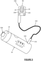
- the non-invasive testing apparatus 10 comprises a probe jack 150 into which the plug 152 of a fly lead 154 can be inserted.
- the fly lead 154 carries at its free end, a clip device 156 comprising opposable pads 158 each comprising a transmit 20 and a receive 24 patch antenna.
- the clip device 156 can be clipped onto the earlobe, or fingertip, say, of a patient, and the test performed in a manner similar to that previously described.
- the device could measure the transmission and reflected characteristics of a part of the body that does not have a natural reflecting internal structure like, but not restricted to bone, or cartilage.
- the clip device 156 can be clipped onto a protrusion 158 manufactured of a calibration material, which protrusion extends from the end cap 24, to enable a calibration sequence to be performed.
- the non-invasive testing apparatus 10 is formed as a wand-type device 109, which can be placed, for example, onto the wrist 111 of a user's hand 220.
- the directional patch antennas (not visible) are located on the side of the device 10. This enables the device to be applied, but is not limited to the wrist and forearm.
- the non-invasive testing apparatus 10 has one or more antennas (not visible) on its underside, which make contact, in use, with the skin of the patient.
- this configuration can make use of the relatively high blood flows present under the skin in the wrist region (radial pulse region), as well as the presence of hard bone structures (ulna and radius) located close to the skin surface.
- the antennae 20, 22, 24 function both in transmission and reflection mode. In this manner both the S21 (transmission) and S11 (reflected) signals are measured.
- the correlation between the blood glucose level and the S11 parameter is derived, together with the S21 parameters such as the resonance frequency shift, "Q" factor of the resonance, group delay, phase, and amplitude variation. In this manner when both the S21 & S11 data are used together, a more accurate value of the blood glucose level is calculated.
- Figure 7 of the drawings is a normalized plot of the magnitude 300 of the received transmitted 302, 304 and received 402, 404 signals as a function of frequency 310 at different blood glucose levels.
- the processor is thus adapted to monitor the points of inflection, i.e. their magnitude and frequency, and to compare these measured values with those in a prepopulated lookup table, from which the blood sugar concertation can be derived.
- the processor can be configured to look-up the magnitude 312 at these target frequencies 314 in a pre-populated lookup table to determine the blood sugar concentration.
- More detailed analysis of the S21 plot 302, 304 can reveal finer textured information, such as from the shape and width of the troughs 308, 316, as well as their frequency and amplitudes. More detailed analysis can be used to verify that the observed effects are consistent with a target substance in the blood (e.g. blood sugar) as opposed to other contamination (e.g. blood alcohol), in which the shape of the observed troughs 308, 316 might be different.
- a target substance in the blood e.g. blood sugar
- contamination e.g. blood alcohol
- Figure 8A is a schematic scatter graph showing the correlation between the S21 and S11 data 500, and if a test result 502 falls outside statistically acceptable boundaries 504, then the confidence of the test result can be questioned, for example, indicating that a re-test is required, or alerting the patient to the possibility of other contamination.
- Figure 8B of the drawings which is a plot on the vertical axis of S21 or S11 measurement versus blood glucose concentration on the horizontal axis at three different frequencies (f1, f2, f3), that there is a correlation between measured S21 or S11 values and the blood glucose concentration.
- Figure 8B which is schematic, also includes trendlines, which correspond to "polynomial models", or equations, for blood glucose concentration at each of the frequencies. It can be seen that statistical outliers are easily identified from this and can be disregarded from certain test results.
- Figure 9 of the drawings shows how the frequency specificity shown in Figure 7 of the drawings can be capitalized upon by using a number of relatively narrow-band antennas, for example, each being tuned to specific narrow frequency bands 550, 552, 554, 556, 558 in which target observations are required.
- the use of a set of relatively narrow-band antennas enables observations to be made at numerous frequencies simultaneously, thus reducing the time taken for a scan/spectroscopic analysis; as well as increasing the sensitivity of the antennas in their frequency bands, rather than employing a less-sensitive broadband antenna.
- the frequency sweep, transmitter & detector circuits may be generated as defined in Patent US 8,882,670 and its derivatives/family.
- an impulse signal may be generated into the biological tissue and the Fast Fourier Transform performed on the received/detected signal in order to derive the frequency response of the system.
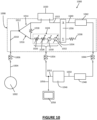
- a circuit 1000 comprises an RF signal generator 1002 adapted, in use, to provide an RF signal at its output 1004.
- the RF signal generator 1002 is connected, via a fly lead 1006 to a test device 1008 in accordance with an aspect of the invention.
- the fly lead 1006 connects to an input 1010 of the test device 1008, which connects to an input node 1012 that splits the RF signal equally into a test component 1014 and a reference component 1016.
- a resistor, 1018 is used to balance the test 1014 and the reference 1016 components.
- the test component 1014 is transmitted into a sample 1020 for analysis. Transmission of the test component 1014 into the sample 1020 is typically accomplished by way of a transmit and/or receive antenna (not shown), which couples the test component 1014 of the RF signal to the sample 1020 and receives a response signal 1022.
- a transmit and/or receive antenna not shown
- the reference component 1016 of the RF signal passes through an adjustable reference circuit 1024, which comprises one or more variable attenuators 1026, 1028, and one or more variable phase shifters 1030, 1032.
- the output 1034 of the adjustable reference circuit 1024, along with the output 1022 of the test component 1014 of the RF signal are provided as inputs to a comparator 1036.
- the comparator 1036 comprises an analogue bridge-type circuit, such as a Wheatstone bridge-type device, which has a summing output 1038, which is not relevant to this disclosure, and a difference output 1040, which is relevant to this disclosure.
- the difference output 1040 is the difference between the output 1022 of the test component 1014 of the RF signal and the output 1034 of the adjustable reference circuit 1024.
- the adjustable reference circuit 1024 can be adjusted such that its amplitude and phase match the specimen under test 1020, then the adjustable reference circuit 1024 will essentially be an analogue of the test specimen 1020 and the difference output 1040 of the comparator 1036 will be zero. The key, therefore, is adjusting the adjustable reference circuit 1024 to meet these criteria.
- an RF demodulator 1042 is provided downstream of the difference output 1040 and that is connected, via a fly lead 1044 to a microprocessor 1046.
- An amplifier/demodulator/signal processing device 1048 may be interposed between the difference output 1040 and the microprocessor 1046, and the details of this 1048 are beyond the scope of this disclosure as they will be readily-understood by the skilled reader.
- the difference 1040 of the comparator 1036 provides an input 1050 for the microprocessor 1046, which is suitably a DC signal that is proportional to the difference 1040 at the output of the comparator 1036; and/or a PWM signal that is representative of the difference 1040 at the output of the comparator 1036.
- the microprocessor 1046 has an output 1052, which is typically connected, via a fly lead 1054, to the adjustable reference circuit 1024.
- the output 1052 of the microprocessor 1046 contains signals which can be used to adjust the parameters of the variable attenuators 1026, 1028 and the phase shifters 1030, 1032.
- the microprocessor effectively executes an algorithm, which adjusts the variable attenuators 1026, 1028 and the phase shifters 1030, 1032 incrementally or continuously until the zero-output condition 1040 at the output of the comparator 1036 is met.
- variable attenuators 1026, 1028 are adjusted (up/down) until the output 1040 of the comparator is minimised (i.e. reaches a minima); then, the phase shifters 1030, 1032 can likewise be adjusted (up/down) until the output 1040 of the comparator 1036 is minimised yet again. This process can be repeated over and over until such time as the output 1040 of the comparator 1036 reaches a minimum, which is ideally a zero output.
- the amplitude and phase of the adjustable reference circuit 1024 are essentially an analogue of the test specimen 1020.
- the adjustment settings of the adjustable reference circuit are equivalent to the amplitude and phase, and hence, are representative, of the parameters of the test specimen 1020.
- These parameters can be outputted 1056 to a display 1058 and therefore it is possible to ascertain the amplitude and phase equivalence of the specimen under test.
- these parameters are not presented to a user in a "raw" state, but are processed in such a way as to provide an indication of the concentration of a target substance, which is ultimately the information that the end-user wants/needs.
- This can be presented graphically and/or numerically and/or audibly (the latter being beneficial for non-sighted patients and/or where the display may not be easily visible).
- test component 1014 and reference component 1016 of the RF signal are equal and because they are compared immediately after the specimen test 1022 and immediately after the adjustable reference circuit 1024, they are effectively independent of the remaining conditions of the circuit, namely the fly leads, etc.
- the apparatus as described herein greatly simplifies an RF measurement because it avoids the need for complex signal generating and signal processing devices, such as network analysers. It is also independent of the physical configuration of the set-up and is thus more immune to extraneous variations in its test results.
- the RF signal generator 1002 comprises a signal generator that is adapted to output an RF signal 1004 at its output, which has a specific frequency, phase, and amplitude. This could, in certain embodiments, be achieved by using a quartz crystal resonator tuned to a particular frequency, although other RF signal generation technologies are within scope of this disclosure. Nevertheless, it will be appreciated that the parameters of the adjustable reference circuit 1024 can be adjusted, by the microprocessor 1046, to obtain an analogue of the sample under test 1020 for a particular RF signal outputted 1004 from the RF signal generator.
- the RF signal generator 1002 can be adjusted to provide a different RF signal, for example having a different frequency, amplitude and/or phase.
- the test procedure can be repeated for this new RF signal and a further set of parameters obtained.
- the RF signal generator 1002 can be configured to "sweep" a particular frequency range, that is to say to vary the frequency of the output continuously, in which case the microprocessor 1046 must be capable of "following” that sweep and determining the parameters of the adjustable reference circuit 1024 almost in real-time.
- the RF signal generator 1002 may be configured to step through a series of discreet frequencies and the microprocessor 1046 can thus be configured to obtain the parameters of the adjustable reference circuit 1024 for each increment of the output signal 1004 of the RF signal generator 1002. In either case, it is possible to obtain a "spectral" analysis of the sample under test 1020 and thus yield the RF properties of the sample under test 1020.
- FIG. 11 a method by which the microprocessor 1046 obtains the parameters of the variable attenuators 1026, 1028 and the variable phase shifters 1030, 1032 to achieve the zero-difference output 1040 is shown.
- the difference ( ⁇ ) at the output 1040 is plotted on the vertical axis, and the attenuation (A) and phase ( ⁇ ) plotted on the horizontal axes.
- the microprocessor 1046 varies the parameters of the variable attenuators 1026, 1028 and the variable phase shifters 1030, 1032, as indicated by the path 1060 until the difference ( ⁇ ) reaches zero 1062, or is minimised as much as possible.
- any real surface plot of difference ( ⁇ ) versus amplitude (A) and phase ( ⁇ ) will not be as shown in Figure 11 , but Figure 11 merely indicates how the microprocessor can "seek" the minimum 1062 by varying together, or sequentially, the settings of the variable attenuators 1026, 1028 and the variable phase shifters 1030, 1032 of the reference circuit 1024.
- a known wearable device 2000 comprises a main body 2002, which has a strap 2004 that passes around a wearer's wrist 2006.
- the main body 2002 has a transmit/receive antenna 2008 on its underside, in contact with the skin of a patient.
- the transmit/receive antenna 2008 transmits an RF signal 2010, which is detected by a receive antenna 2012 formed in a housing 2014 located on the opposite side of a user's wrist.
- the attenuation and/or phase of the transmitted signal 2010 is detected by the device 2000 and a reading is thus obtained.
- the housing 2014 comprises an RF reflector that reflects a transmitted signal 2016 back towards the transmit/receive antenna 2008 of the main body 2002. Again, differences in the attenuation and/or phase of the reflected signal 2018 are picked up by the transmit/receive antenna 2008 of the wearable device 2000 and a reading can thus be obtained.
- the known wearable device 2000 requires the housing 2014 to be at a fixed position relative to the main body 2002 such that the transmitted signal 2010 can be picked-up by a receiver 2012 of the housing 2014; or so that the transmitted signal 2016 can be reflected off the reflector of the housing 2014 back to the transmit/receive antenna 2008 of the main body 2002.
- some form of predetermined alignment 2020 is required between the main body 2002 and the housing 2014.
- the wearable device 3000 comprises a main body 3002, which comprises a transmit/receive antenna 3004, which sends a transmit signal 3006 to a receiver 3008 incorporated into a housing 3010 placed opposite the main body 3002.
- the transmit/receive antenna 3004 can send out a signal 3012 which is reflected off a reflector incorporated into the housing 3010 to reflect the signal 3014 back to the transmit/receive antenna 3004 of the main body. It can be seen that the main body 3002 and housing 3010 are aligned and lie on a centreline 3016, which, ideally, passes through the centres of the main body 3002 and housing 3010 and, preferably still, at right angles to both.
- the wearable device 3000 comprises a strap 3020, which has a fixed end 3022, which passes around the left-hand side (in the drawing) of the user's wrist 2016, around a pully/roller 3024 connected to the left-hand side (in the drawings) of the housing 3010 and back around the user's wrist 2016.
- the strap 3020 passes underneath (in the illustrated embodiment, although it could be over) the main body 3002, around a further set of optional guide rollers 3026 and then around the right-hand side (in the illustrated embodiment) of the user's wrist 2016 to a further roller 3028.
- the strap 3020 then passes back around the right-hand side of the user's wrist (in the illustrated embodiment) and terminates in a free end 3030, which can be secured 3032 back on Suitably, the at least one antenna is operatively coupled to the skin of a patient, and hence to the patient's blood.
- the strap 3020 has two strap portions 3024, 3026 of approximately equal lengths on either side of the user's wrist 2016.
- This "pulley type” configuration means that when the free end 3030 of the strap 3020 is pulled, the strap will shorten equally on either side of the user's wrist 2016 resulting in the housing 3010 being drawn towards the main body 3002 in a substantially straight line - thereby maintaining the desired alignment between the main body 3002 and the housing 3010.
- FIG. 15 of the drawings it can be seen that the same wearable device 3000 has been fitted to a different sized user's wrist 2016' and that the alignment of the main body 3002 relative to the housing 3010 has been preserved. It will be appreciated by comparing the invention of Figure 15 with the prior art as illustrated in Figure 13 , that in this case, adjustment of the strap 3020 does not result in breaking the requisite alignment of the housing 3010 relative to the main body 3002 and therefore, the transmitted 3006 and reflected 3012 3014 signals do not "miss" their respective targets, namely the receiver/reflector of the housing 3010 located on the opposite side of the wrist 2016 to the main body 3002.
- a wearable device 3000 in accordance with embodiments of the invention can be reliably fitted to different wrist sizes and still maintain its functionality, unlike known wearable devices 2000 (as shown in Figures 12 and 13 , for example) where adjustment to the strap 2004 can result in misalignment of the housing 2014 relative to the main body 2002, or in other words - unequal spacing on opposite sides of the wrist between the main body 2002 and the housing 2012.
- the wearable device 4000 comprises a main body 4002 which is held onto a user's wrist 4004 using an adjustable strap 4006.
- the strap can be adjusted using a clasp 4008, buckle or other suitable device.
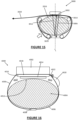
- the wearable device 4000 is worn loosely around the wrist 4004 and thus there is a small air gap 4010 between the underside of the main body 4002 and the skin surface 4012 directly beneath it.
- the main body 4002 comprises an RF antenna 4014 which, in order to work correctly, needs to be coupled effectively to the surface 4012 of the user's skin. With the wearable device 4000 fitted loosely, as shown in Figure 16 , this is not possible or reproducible due to the air gap 4010 between the antenna 4014 and the user's skin 4012.
- the wearable device 4000 comprises an inflatable air bladder 4016, which is interposed between a rear surface 4018 of the antenna 4014 and the main body 4002.
- the air bladder 4016 can be inflated using a pump, which in the illustrated embodiment, comprises a small sac 4020 that can be pressed repeatedly to expel air into the bladder 4016 via a small tube 4022.
- the sac 4020 has been pressed 4024 repeatedly and air within it has been discharged, via the tube 4022 into the bladder 4016 which has now become inflated.
- a one-way/pressure-relief valve 4026 Interposed between the sac 4020 and the airbladder 4016 is a one-way/pressure-relief valve 4026, which ensures, on the one hand, that air expelled from the sac 4020 is directed into the bladder 4016; and which also prevents over-inflation of the airbladder.
- the setting of the pressure-relief valve 4026 can be adjusted (or factory set) such that the internal air pressure 4028 within the air sac 4016 is sufficient to ensure that the force 4030 applied by the antenna 4014 onto the surface of the user's skin 4012 is at least a predetermined press-on force.
- the airbladder 4016 is inflated using air pressure, that the internal pressure 4028 will be hydrostatic, that is to say applied evenly to the rear surface 4018 of the antenna 4014 and thus the press-on force 4030 of the antenna 4014 onto the skin surface 4012 will be substantially even across the entire surface of the antenna 4014 also.
- an electronic air pressure sensor located within the air bladder 4016, which emits an audible and/or visual signal via a display/audible output of the wearable device 4000 when the internal air pressure 4028 was in the airbladder 4016 is below the predetermined pressure.
- a user can, when either alerted or wishes to carry out a test, inflate the bladder 4016 using the sac 4020 by pressing 4020 repeatedly upon it. Air from the sac 4020 will be expelled into the bladder 4016 to inflate it and - up to the point that the minimum required pressure has been reached, the audible and/or visual signal will sound/display indicating to the user to carry on pressing the sac 4020.
- the pressure relief valve 4026 Upon reaching the desired internal pressure 4028, the pressure relief valve 4026 will operate to prevent further air entering, and thus over-inflating, the airbladder. At the same time, the air pressure sensor will trigger the wearable device 4000 to stop emitting a "keep pumping" signal and thus the user can be sure that the air bladder has been correctly inflated, and the required press-on force 4030 has been attained. An RF test, using the antenna 4014 can then be commenced in a manner described herein.
- the embodiment of the invention shown in Figures 16 and 17 enables a wearable device 4000 to be worn loosely/in accordance with user preference for most of the time, but readily enables the antenna 4014 to be pressed onto the user's skin 4012 with a predetermined and easily reproducible force thereby ensuring reproducibility of an RF test carried out using the antenna 4014.
- the airbladder 4016 can be deflated, at which point the "comfort setting" of the strap, 4006 returns to its pre-test state and the user can carry on.
- self-adhesive antenna patch 5000 in accordance within embodiments of the invention is shown, which has on its underside, one or more antennas 20, 22, 24 as described previously with reference to Figures 1 , 2 and 9 , etc. above.
- the antenna or antennas work in the manner previously described to obtain an RF test result.
- the underside of the self-adhesive antenna patch 5000 comprises a central region 5002 which is non-, or largely non-adhesive surrounded by a self-adhesive region 5004 that is covered with a water-resistant, pressure-sensitive adhesive - as will be well understood to the skilled reader.
- the self-adhesive antenna 5000 can therefore be stuck onto a patient's skin (not shown) and remain there for a period of time. As such, during the time that the self-adhesive antenna patch 5000 is adhered to the patient's skin, any test results obtained using the antenna(s) will be independent of variations in the location of the antennas relevant to the patient's body. This overcomes many of the extrinsic variables associated with taking RF readings on a patient that moves a lot.
- the top side of the self-adhesive antenna patch 5000 is shown in Figure 19 of the drawings, and comprises a button type connector 5006, which provides one or more electrical contacts for a test circuit (not shown) interposed between the connector 5006 and the antennas on the underside of the self-adhesive antenna 5000 is a calibration circuit 5008, which shall be described below.
- the calibration circuit 5008 is interposed between the connector 5006 and the antenna, indicated schematically as 20 in Figures 20 , 21 and 22 , although it will be appreciated that, in reality, the antennas 20 are more like those shown in Figure 18 of the drawings.
- the connector 5006 comprises a signal line 5010 to which is applied a test RF signal 5012 by a signal generator/analyser 5014 connected, via a fly lead 5016 to a complimentary connector 5018 at its free end.
- the fly lead's connector 5018 electrically connects to the connector 5006 of the self-adhesive antenna 5000 in a manner that will be readily understood.
- the fly lead 5016 is shielded by a grounding sheath 5020, which is grounded 5022 in the manner that will be readily understood to the skilled reader.
- a test signal 5010 can be sent to the antenna 20 via the fly lead 5016 and the calibration circuit 5008.
- the calibration circuit 5008 comprises a solid-state switch, which is a single pole-four throw switch having four output terminals.
- a first one of the output terminals 5024 is not connected to anything and thus is an open-circuit connection.
- a second one of the output terminals 5026 is connected to the antenna 20.
- a third one of the output terminals 5028 is connected to ground 5022 via a reference load 5030 (typically a 50-ohm load).
- a fourth output terminal 5032 is connected directly to ground 5022.
- the input pole 5034 of the solid-state switch 5022 can thus be connected to any one of the four output terminals 5024, 5026, 5028, 5032 to carry out an open-circuit calibration routine, a closed-circuit test routine and a reference load test routine.
- the transmission system that is to say the fly lead 5016 and connectors 5018, 5016 can be calibrated-out and thus the actual RF signal response of the antenna can be more accurately measured regardless of the instantaneous configuration of the fly lead 5016 and connectors 5018, 5006.
- the on-board/in-situ calibration apparatus previously described can, of course, be used on a transmit-receive system, such as a clamp-on device as shown in Figure 5 of the drawings.
- the clamp-on probe 156 comprises a transmit antenna 20 on one side of an earlobe 90 and a receive antenna 24 located on the opposite side of the earlobe 90.
- the probe 156 is connected via fly lead 154 to a RF signal generator analyser and is thus potentially susceptible to substantial amounts of extrinsic variables.
- an on-board calibration device to each of the antennas 20, 24, it is possible to calibrate-out any such extrinsic variables in the manner previously described.
- a typical calibration device 5008 suitable for us in conjunction with the probe 156 of Figure 5 is shown.
- the calibration device comprises two calibration devices as shown in Figure 20 , but with the addition of a bypass conductor 5050 which bypasses the transmit 20 and receive antennas 24 and so a signal 5010 can be transmitted from a transmitter 5014 via a fly lead 5016/connector 5018, 5006, through the bypass conductor 5050 and back to the signal generator/analyser 5014 via the same, or a different fly lead 5016.
- the switch means 5022 comprises a fifth throw position 5052, which enables the test signal 5010 to be transmitted via the bypass conductor 5050 directly back to the RF signal generator/analyser 5014 and therefore, calibrate the fly lead 5016 and connectors 5018, 5006 out of the system.
- either of the switches 5002 can be set to the previously described positions, namely open-circuit closed-circuit and reference load to calibrate each of the antennas 20, 24 independently as well. It will be appreciated that the invention thus overcomes many of the practical restrictions/problems associated with using RF measurements techniques in situations where the subject and/or test equipment can move considerably.
- a self-adhesive antenna patch 5000 has been stuck to the patient's skin 4012 on the patient's wrist 4004 in a similar manner to that shown in Figures 16 and 17 of the drawings.
- the connector 5006 comprises a button-type connector, which engages a complimentary socket 5060 provided on the underside of a wearable device 4000.
- the wearable device 4000 is able to achieve a calibrated connection to the self-adhesive patch antenna 5000 whilst ensuring that the self-adhesive patch antenna always stays in the same place relative to the patient's wrist 4004 from one test to the next.
- Embodiments of the invention may allow the measurements taken to be transmitted to external devices to monitor their blood-glucose level whilst using their home computer or smart phone or similar device and allow for remote logging of blood-glucose levels. This feature could prove to be most useful for carefully monitoring the condition of elderly sufferers and enable medical practitioners to provide emergency help should the patient's levels become excessively high or low. Remote monitoring and data logging can also be used to provide a useful tool to the patient or the doctor/healthcare professional to develop a response plan to assist with the management of the disease.
Landscapes
- Health & Medical Sciences (AREA)
- Life Sciences & Earth Sciences (AREA)
- Physics & Mathematics (AREA)
- Engineering & Computer Science (AREA)
- Animal Behavior & Ethology (AREA)
- Veterinary Medicine (AREA)
- Biophysics (AREA)
- Biomedical Technology (AREA)
- Heart & Thoracic Surgery (AREA)
- Medical Informatics (AREA)
- Molecular Biology (AREA)
- Surgery (AREA)
- Pathology (AREA)
- General Health & Medical Sciences (AREA)
- Public Health (AREA)
- Optics & Photonics (AREA)
- Nuclear Medicine, Radiotherapy & Molecular Imaging (AREA)
- Radiology & Medical Imaging (AREA)
- Emergency Medicine (AREA)
- Artificial Intelligence (AREA)
- Computer Vision & Pattern Recognition (AREA)
- Physiology (AREA)
- Psychiatry (AREA)
- Signal Processing (AREA)
- Measurement Of The Respiration, Hearing Ability, Form, And Blood Characteristics Of Living Organisms (AREA)
- Measuring And Recording Apparatus For Diagnosis (AREA)
Claims (15)
- Nicht-invasive Testvorrichtung zum Bestimmen einer Konzentration einer Zielsubstanz im Blut eines Patienten, wobei die nicht-invasive Testvorrichtung Folgendes umfasst:einen HF-Signalgenerator (1002), der dazu eingerichtet ist, im Gebrauch ein ausgegebenes HF-Signal (102, 1004) auszugeben;einen Prozessor (82, 1046); undmindestens eine Antenne (20), die im Betrieb mit dem Blut des Patienten wirkgekoppelt ist, wobei die oder mindestens eine Antenne (20) mit dem HF-Signalgenerator (102, 1004) und dem Prozessor (82, 1046) wirkverbunden ist,wobei der Prozessor für folgenden Gebrauch eingerichtet ist:Messen eines gesendeten oder reflektierten Antwortsignals (300, 1022) über mindestens eine der Antennen, wobei das Antwortsignal (300, 1022) eine Funktion des durch eine Interaktion mit dem Patientenblut modifizierten HF-Ausgangssignals (102, 1004) ist, Messen der Amplitude und der Phase des Antwortsignals (300, 1022) bei einer Vielzahl von Ausgangs-HF-Signalfrequenzen;Darstellen des Verlaufs der gemessenen Amplitude und Phase des Antwortsignals (300, 1022) in Abhängigkeit von ausgegebenen HF-Signalfrequenzen;Bestimmen von zwei oder mehr abgeleiteten Parametern des Antwortsignals (300, 1022) aus der Gruppe unter Verwendung der Darstellung des Verlaufs, umfassend: einen Q-Faktor der Resonanz; eine Gruppenverzögerung; einen Formfaktor der Darstellung des Verlaufs; und einen Gradienten der Darstellung des Verlaufs bei verschiedenen Frequenzen; undBestimmen der Konzentration der Zielsubstanz im Blut des Patienten durch:
den Prozessor (82, 1046) der für Folgendes eingerichtet ist:Vergleichen der Vielzahl von abgeleiteten Parametern mit jeweiligen Modellen der jeweiligen abgeleiteten Parameter in Abhängigkeit von der Konzentration der Zielsubstanz im Blut;Bestimmen einer Konzentration der Zielsubstanz im Blut des Patienten für jeden abgeleiteten Parameter basierend auf einer Korrelation zwischen dem jeweiligen abgeleiteten Parameter und den entsprechenden Konzentrationswerten der Zielsubstanz im Blut des Patienten in dem jeweiligen Modell; undAnwenden eines statistischen Modells auf die sich ergebenden bestimmten Konzentrationen der Zielsubstanz im Blut des Patienten, basierend auf jedem abgeleiteten Parameter, um zu einer einzelnen, insgesamt bestimmten Konzentration der Zielsubstanz im Blut des Patienten zu gelangen. - Vorrichtung nach Anspruch 1, ferner umfassend Bestimmen eines oder mehrerer Parameter des Antwortsignals aus der Gruppe unter Verwendung des Verlaufs, umfassend: eine Resonanzfrequenzverschiebung (554); eine Phasenverschiebung; und eine Amplitudenvariation (312).
- Vorrichtung nach Anspruch 1 oder Anspruch 2, wobei jedes Modell eines oder mehrere von Folgendem umfasst:eine Look-Up-Tabelle abgeleiteter Parameter und ihrer entsprechenden Konzentrationen der Zielsubstanz im Blut des Patienten, wobei der Prozessor (82, 1046) dazu eingerichtet ist, die nächste Übereinstimmung mit Daten in der Look-Up-Tabelle zu identifizieren oder zwischen Daten in der Look-Up-Tabelle zu interpolieren, um zu einer bestimmten Konzentration der Zielsubstanz im Blut des Patienten zu gelangen; undeine Gleichung, die eine Beziehung zwischen einem abgeleiteten Parameter und der Konzentration der Zielsubstanz im Blut des Patienten definiert, und wobei der Prozessor (82, 1046) dazu eingerichtet ist, den abgeleiteten Parameter als Begründung der Gleichung zu verwenden, um den Wert zu erhalten, der die Konzentration der Zielsubstanz im Blut des Patienten ist.
- Vorrichtung nach Anspruch 1, 2 oder 3, wobei die Amplitude und Phase des Antwortsignals (300, 1022) durch eine Schaltung (1000) gemessen werden, in der:der Ausgang (1010) des HF-Signalgenerators (1002) mit einem Eingangsknoten (1012) verbunden ist, wobei der Eingangsknoten (1012) dazu eingerichtet ist, im Gebrauch das HF-Signal in im Wesentlichen gleiche erste (114) und zweite Signale (1016) aufzuteilen, wobei das erste Signal (1014) über die Antenne (1020) mit einem Testausgang (1022) verbunden ist,das zweite Signal (1016) über eine einstellbare Referenzschaltung (1024) mit einem Referenzausgang (1034) verbunden ist,der Testausgang (1022) und der Referenzausgang (1034) mit jeweiligen Eingängen eines Komparators (1036) verbunden sind, wobei der Komparator (1036) dazu eingerichtet ist, an einem Komparatorausgang (1040) eine Differenz zwischen dem Testausgang (1022) und dem Referenzausgang (1034) auszugeben,die Schaltung (1000), ferner umfassend einen Mikroprozessor (1046), umfassend:einen Mikroprozessoreingang (1050), der mit dem Komparatorausgang (1040) verbunden ist; undeinen Steuerausgang (1052), der mit der Referenzschaltung (1024) verbunden ist; wobeidie Referenzschaltung (1024) ein variables Dämpfungsglied (1026, 1028) umfasst und einen variablen Phasenschieber (1030, 1032), der durch den Steuerausgang (1052) des Mikroprozessors (1046) steuerbar ist, und wobei der Mikroprozessor (1046) zu folgendem Gebrauch eingerichtet ist:Einstellen seines Steuerausgangs (1052) und dadurch Einstellen der Amplitude und Phase der Referenzschaltung (1024), um den Komparatorausgang (1040) auf null oder im Wesentlichen auf null zu bringen, wodurch die einstellbare Referenzschaltung (1024) so eingestellt wird, dass sie ein Analogon des Körperteils ist, das das Blut enthält; undAusgabe eines Datensignals (1056), das die Amplitude und Phase der Referenzschaltung (1024) angibt, wobei der Komparatorausgang (1040) null oder im Wesentlichen null ist.
- Vorrichtung nach Anspruch 4, wobei die effektiven Pfadlängen von Leitern, die das erste (1014) und zweite Signal (1016) zwischen dem Eingangsknoten (1012) und den Eingängen (1022, 1034) des Komparators (1036) tragen, gleich oder im Wesentlichen gleich sind.
- Vorrichtung nach Anspruch 4 oder Anspruch 5, ferner umfassend eines oder mehrere von Folgendem:Mittel (1042, 1048) zum Umwandeln des Komparatorausgangs in ein DC- oder PWM-Signal am Mikroprozessoreingang (1050), wobei das DC- oder PWM-Signal proportional zum Komparatorausgang (1040) ist; undeine Anzeigevorrichtung (1058), wobei das Datensignal (1056) - das die Amplitude und Phase der Referenzschaltung (1024) angibt, wobei der Komparatorausgang (1040) null oder im Wesentlichen null ist - auf der Anzeigevorrichtung (1024) dargestellt wird, d.h. ein Anzeigeschirm, ein LCD-Feld oder ein oder mehrere Zeiger ist/sind.
- Vorrichtung nach einem der Ansprüche 4 bis 6, umfassend eine Anschlussleitung (1006, 1054, 1044), die einen oder mehrere der folgenden Elemente verbindet: den HF-Signalgenerator (1002) und den Eingangsknoten (1012); den Komparatorausgang (1040) und den Mikroprozessoreingang (1050); den Steuerausgang (1052) des Mikroprozessors und die Referenzschaltung (1024); den HF-Signalgenerator (1002) und eine Antenne (1020); und eine Antenne (1020) und den Prozessor (1046), wobei die oder jede Anschlussleitung (1006, 1054, 1044) einen lösbaren Verbinder umfasst.
- Vorrichtung nach Anspruch 7, ferner umfassend eine Kalibriervorrichtung (8000), bei der die Antenne (20) mit einem Verbinder (5006) verbunden ist, der einen Verbindereingang aufweist, der im Gebrauch mit einem entsprechenden Verbinder (5018) der Anschlussleitung verbindbar ist und wobei die Kalibriervorrichtung (8000) umfasst:
Schaltmittel (5022), d. h. ein Festkörperschalter, bei dem es sich um einen einpoligen Vier-Wege-Schalter mit vier Ausgangsklemmen (5024, 5026, 5028, 5032) handelt, der zwischen einem Ausgang des Verbinders und der Antenne (20) zwischengeschaltet ist, wobei die Schaltmittel (5022) Folgendes aufweisen:einen Eingang (5034), der mit dem Ausgang (5010) des Verbinders (5006) verbunden ist;einen ersten Ausgang (5026), der mit der Antenne (20) verbunden ist;einen zweiten Ausgang (5024), der mit einer offenen Schaltung verbunden ist;einen dritten Ausgang (5032), der mit der Erdung verbunden ist; undeinen vierten Ausgang (5028), der mit einer Referenzlast (5030) verbunden ist, dadurch gekennzeichnet, dass:das Schaltmittel (5022) im Gebrauch betätigt werden kann, um den Verbinder (5006) selektiv mit jedem der vier Ausgänge (5024, 5026, 5028, 5032) individuell derart zu verbinden, dass im Gebrauch die Antenne (20) relativ zu einem Signalübertragungssystem kalibriert werden kann, das mit dem Eingang des Verbinders verbunden ist, unddie Referenzlast (5030) optional eine im Wesentlichen 50 Ω Last umfasst. - Vorrichtung nach Anspruch 8, wobei die Schaltmittel (5022) dazu eingerichtet ist, ein HF-Eingangssignal zu jedem seiner vier Ausgänge (5024, 5026, 5028, 5032) in Folge zu zyklieren, sodass gemessene Reaktionen für jede Schalterposition analysiert und in einem Kalibrierungsalgorithmus oder einer Kalibrierungsmatrix verwendet werden können, um die Antenne (20) zu kalibrieren und dabei Größen, die einem angeschlossenen Signalübertragungssystem zugeordnet sind, auszuklammern.
- Vorrichtung nach Anspruch 8 oder Anspruch 9, wobei die Schaltmittel (5022) ferner eine fünfte Ausgangsposition (5052) umfassen, die den Ausgang (5010) eines ersten Verbinders (5006), der einer ersten Antenne (20) zugeordnet ist, mit einem Ausgang eines zweiten Verbinders, der einer zweiten Antenne (24) zugeordnet ist, verbindet (5050).
- Vorrichtung nach einem der vorhergehenden Ansprüche, wobei der HF-Signalgenerator (1002) eine oder mehrere der Gruppe umfasst, umfassend:eine stabile Resonatorschaltung, die in der Lage ist, ein HF-Signal mit einer im Wesentlichen konstanten Amplitude, Frequenz und Phase auszugeben;Mittel zum selektiven Einstellen einer oder mehrerer der Amplituden, Frequenzen und Phasen des HF-Signals an seinem Ausgang;Mittel zum kontinuierlichen Einstellen einer oder mehrerer der Frequenzen, Amplituden und Phasen des HF-Signals an seinem Ausgang;Mittel zum schrittweisen Einstellen einer oder mehrerer der Frequenzen, Amplituden und Phasen des HF-Signals an seinem Ausgang;eine Vielzahl von Resonatoren, die jeweils dazu konfiguriert sind, ein unterschiedliches Frequenz-, Amplituden- und/oder Phasen-HF-Signal auszugeben, und Schaltmittel zum selektiven Verbinden eines ausgewählten einen der Vielzahl von Resonatoren mit dem Ausgang des HF-Signalgenerators, sodass der HF-Signalgenerator ein HF-Signal mit einer selektiven Frequenz, Amplitude und/oder Phase selektiv ausgeben kann;eine Vielzahl von frequenzangepassten Antennen, wobei jede frequenzangepasste Antenne auf eine bestimmte Bandbreite abgestimmt ist wobei der HF-Signalgenerator (1002) konfiguriert ist, um eine entsprechende Vielzahl von schmalbandigen Ausgangssignalen an jede der frequenzangepassten Antennen (20) auszugeben; undMittel zum Ausgeben eines 1 bis 10 ms-Burstsignals, wobei der Prozessor (82, 1046) eingerichtet ist, das Antwortsignal aus dem Zeitbereich in den Frequenzbereich zu transponieren, um ein Frequenzspektrum aus dem Burstsignal zu erlangen, wobei der Prozessor (82, 1046) eingerichtet ist, eine Z-Transformation anzuwenden, um aus dem Antwortsignal ein Frequenzspektrum abzuleiten.
- Vorrichtung nach einem der vorhergehenden Ansprüche, wobei der Prozessor eingerichtet ist, die Genauigkeit der abgeleiteten Konzentration der Zielsubstanz zu verifizieren, indem das reflektierte Antwortsignal gegen das übertragene Antwortsignal dargestellt wird, indem überprüft wird, dass der Datenpunkt für die abgeleitete Zielsubstanzkonzentration in einen statistisch akzeptablen Bereich eines kalibrierten Zielsubstanzkonzentrations-Streudiagramms fällt.
- Vorrichtung nach einem der vorhergehenden Ansprüche, umfassend:einen Hauptkörper (3002), umfassend die mindestens eine Antenne, die im Gebrauch mit der Haut eines Patienten wirkgekoppelt ist; undein Gehäuse (3010), das mindestens eine Empfangsantenne und/oder einen Reflektor umfasst, die im Gebrauch ebenfalls mit der Haut eines Patienten wirkgekoppelt sind, wobei das Gehäuse (3010) im Gebrauch auf einer dem Hauptkörper (3002) gegenüberliegenden Seite der Anatomie des Patienten angeordnet ist; undeinen verstellbaren Gurt (3020), der den Hauptkörper (3002) mit dem Gehäuse (3010) verbindet, dadurch gekennzeichnet, dass:der Gurt (3020) als ein Riemenscheibenband ausgebildet ist, das an einem Ende an dem Hauptkörper (3002) oder Gehäuse (3010) befestigt ist, das um jeweilige Rollen des Hauptkörpers (3002) und des Gehäuses (3010) gewickelt ist und das ein freies Ende (3020) aufweist, wobei das Riemenscheibenband und die Rollen konfiguriert sind, das Gehäuse (3010) relativ zu dem Hauptkörper (3020) derart zu zentralisieren, dass durch Ziehen an dem freien Ende (3020) der Gurt (3020) den Abstand zwischen dem Hauptkörper (3002) und dem Gehäuse (3010) verringert, während eine im Wesentlichen konstante Ausrichtung zwischen dem Hauptkörper (3002) und dem Gehäuse (3010) beibehalten wird,die Rollen drehbar an dem Hauptkörper (3002) und Gehäuse (3010) befestigt sind, wobeider Gurt (3020) an einem Ende an dem Hauptkörper verankert ist und um das Handgelenk oder ein anderes Körperteil eines Benutzers zu einer ersten Rolle läuft, die sich an einer Seite des Gehäuses (3010) befindet, wobei sich der Gurt auf sich selbst zurückfaltet und sich um die gleiche Seite des Handgelenks oder Körperteils des Benutzers zurück zum Hauptkörper (3010) erstreckt, wobei sich der Gurt um die gegenüberliegende Seite des Handgelenks oder Körperteils des Benutzers zu einer zweiten Rolle erstreckt, die sich auf einer gegenüberliegenden Seite des Gehäuses (3010) befindet, sodass auf jeder Seite eine gleiche Anzahl von Gurtlängen auf beiden Seiten des Handgelenks oder Körperteils des Benutzers bereitgestellt werden, sodass ein Ziehen am freien Ende des Gurts (3020) eine Bewegung des Gehäuses relativ zum Hauptkörper bewirkt, wodurch die Gurtlängen auf beiden Seiten des Handgelenks oder Körperteils des Benutzers im Wesentlichen gleich oder gleich sind.
- Vorrichtung nach einem der vorhergehenden Ansprüche, umfassend:einen Hauptkörper (4002), umfassend die mindestens eine Antenne (4014) mit einer Frontfläche, die im Gebrauch operativ mit der Haut (4012) eines Patienten gekoppelt ist; undeinen verstellbaren Gurt (4006), der mit dem Hauptkörper (4002) verbunden ist und sich im Gebrauch um einen Teil des Körpers des Patienten erstreckt, um die Antenne (4014) angrenzend an die Haut des Patienten (4012) zu halten,die nicht-invasive Testvorrichtung, ferner umfassend:eine Luftblase (4016);Mittel (4020) zum Aufblasen der Luftblase (4016), um zu bewirken, dass die Vorderfläche der Antenne (4014) mit einer vorbestimmten Kraft gegen die Haut (4012) des Patienten drückt; undein Druckentlastungsventil (4022), das zwischen der Einrichtung zum Aufblasen (4020) und der Luftblase (4016) angeordnet ist, wobei:das Mittel zum Aufblasen der Blase (4020) eine Handpumpe umfasst, wobei die Handpumpe eine komprimierbare Blase mit einem verbundenen Auslass umfasst, der über ein Einwegventil mit einem Einlass der Luftblase (4016) verbunden ist; undoptional umfassend einen Luftdrucksensor, der im Gebrauch dazu eingerichtet ist, anzuzeigen, wenn der Luftdruck in der Luftblase (4016) unter einem Luftdruck liegt, der der vorbestimmten Kraft entspricht.
- Vorrichtung nach einem der vorhergehenden Ansprüche, wobei der Prozessor entweder:in einen Hauptkörperabschnitt der nicht-invasiven Testvorrichtung integriert ist; oderphysikalisch oder logisch getrennt von einem Hauptkörper der nicht-invasiven Testvorrichtung und mit einer I/O-Schnittstelle, die im Betrieb den Treiber und Prozessor mit einer zusätzlichen Verarbeitungseinheit in Wirkverbindung bringt, wobei die zusätzliche Verarbeitungseinheit in einer oder mehreren der Gruppe angeordnet ist, umfassend:eine zugehörige externe Verarbeitungseinheit;eine Smartphone-Vorrichtung;eine Tablet-Computervorrichtung;einen Personal Computer undeinen cloudbasierten Computerserver.
Applications Claiming Priority (2)
| Application Number | Priority Date | Filing Date | Title |
|---|---|---|---|
| GBGB1602773.2A GB201602773D0 (en) | 2016-02-17 | 2016-02-17 | A method and apparatus for measuring the concentration of target substances in blood |
| PCT/GB2017/050389 WO2017141024A2 (en) | 2016-02-17 | 2017-02-15 | A method and apparatus for measuring the concentration of target substances in blood |
Publications (3)
| Publication Number | Publication Date |
|---|---|
| EP3416540A2 EP3416540A2 (de) | 2018-12-26 |
| EP3416540C0 EP3416540C0 (de) | 2024-12-25 |
| EP3416540B1 true EP3416540B1 (de) | 2024-12-25 |
Family
ID=55697789
Family Applications (1)
| Application Number | Title | Priority Date | Filing Date |
|---|---|---|---|
| EP17708569.3A Active EP3416540B1 (de) | 2016-02-17 | 2017-02-15 | Vorrichtung zur messung der konzentration von zielsubstanzen im blut |
Country Status (15)
| Country | Link |
|---|---|
| US (1) | US11253174B2 (de) |
| EP (1) | EP3416540B1 (de) |
| JP (1) | JP6990187B2 (de) |
| CN (1) | CN108882849B (de) |
| AU (1) | AU2017219994B2 (de) |
| CA (1) | CA3014716A1 (de) |
| CL (1) | CL2018002308A1 (de) |
| ES (1) | ES3006934T3 (de) |
| GB (1) | GB201602773D0 (de) |
| MX (1) | MX2018009787A (de) |
| NZ (1) | NZ745812A (de) |
| PL (1) | PL3416540T3 (de) |
| RU (1) | RU2745294C2 (de) |
| WO (1) | WO2017141024A2 (de) |
| ZA (1) | ZA201806045B (de) |
Families Citing this family (61)
| Publication number | Priority date | Publication date | Assignee | Title |
|---|---|---|---|---|
| KR101925632B1 (ko) * | 2017-01-26 | 2018-12-05 | 울산과학기술원 | 체내 이식형 혈당 측정 장치 및 방법 |
| JP7023751B2 (ja) * | 2018-03-14 | 2022-02-22 | オムロン株式会社 | 生体情報測定装置 |
| US10631753B2 (en) | 2018-03-22 | 2020-04-28 | Arnold Chase | Blood glucose tracking system |
| US11998307B2 (en) | 2018-03-22 | 2024-06-04 | Arnold Chase | Continuous blood glucose monitor |
| GB2576475B (en) * | 2018-04-18 | 2022-12-21 | Afon Tech Limited | A method and apparatus for measuring the concentration of target substances in blood |
| US12059239B2 (en) | 2018-05-08 | 2024-08-13 | Know Labs, Inc. | Electromagnetic shielding in non-invasive analyte sensors |
| US11903689B2 (en) * | 2019-12-20 | 2024-02-20 | Know Labs, Inc. | Non-invasive analyte sensor device |
| US11464419B2 (en) * | 2018-12-18 | 2022-10-11 | Movano Inc. | Methods for training a model for use in radio wave based health monitoring |
| KR102378779B1 (ko) * | 2019-06-21 | 2022-03-25 | 울산과학기술원 | 생체 센싱을 위한 공진기 조립체 및 전자기파를 이용한 바이오 센서 |
| JP2022537642A (ja) | 2019-06-21 | 2022-08-29 | ユニスト(ウルサン ナショナル インスティテュート オブ サイエンス アンド テクノロジー) | アレイアンテナを利用したバイオセンサ |
| US12347925B1 (en) * | 2019-06-25 | 2025-07-01 | Amazon Technologies, Inc. | Radio frequency antenna for wearable device |
| JP7102469B2 (ja) * | 2019-08-02 | 2022-07-19 | 華廣生技股▲ふん▼有限公司 | センサーを搭載するための容器及びその操作方法 |
| US11234619B2 (en) * | 2019-12-20 | 2022-02-01 | Know Labs, Inc. | Non-invasive detection of an analyte using decoupled transmit and receive antennas |
| TW202143659A (zh) * | 2019-12-20 | 2021-11-16 | 美商知道實驗室股份有限公司 | 具去耦發射與接收天線之非侵入式分析物感測器及系統 |
| US11063373B1 (en) | 2019-12-20 | 2021-07-13 | Know Labs, Inc. | Non-invasive analyte sensor and system with decoupled transmit and receive antennas |
| US11031970B1 (en) * | 2019-12-20 | 2021-06-08 | Know Labs, Inc. | Non-invasive analyte sensor and system with decoupled and inefficient transmit and receive antennas |
| US11058317B1 (en) | 2019-12-20 | 2021-07-13 | Know Labs, Inc. | Non-invasive detection of an analyte using decoupled and inefficient transmit and receive antennas |
| US11330997B2 (en) * | 2020-02-06 | 2022-05-17 | Know Labs, Inc. | Detection of an analyte using different combinations of detector elements that can transmit or receive |
| JP2023512580A (ja) * | 2020-02-06 | 2023-03-27 | ノウ・ラブズ・インコーポレイテッド | 送信または受信できる複数の検出器要素を備えた検体センサおよびシステム |
| US11193923B2 (en) | 2020-02-06 | 2021-12-07 | Know Labs, Inc. | Detection of an analyte using multiple elements that can transmit or receive |
| US11058331B1 (en) | 2020-02-06 | 2021-07-13 | Know Labs, Inc. | Analyte sensor and system with multiple detector elements that can transmit or receive |
| CN115135241A (zh) * | 2020-02-18 | 2022-09-30 | 朴英权 | 非侵入式血糖检测仪 |
| US11832926B2 (en) | 2020-02-20 | 2023-12-05 | Know Labs, Inc. | Non-invasive detection of an analyte and notification of results |
| US12089927B2 (en) | 2020-02-20 | 2024-09-17 | Know Labs, Inc. | Non-invasive analyte sensing and notification system with decoupled and inefficient transmit and receive antennas |
| US12023151B2 (en) | 2020-02-20 | 2024-07-02 | Know Labs, Inc. | Non-invasive analyte sensing and notification system with decoupled transmit and receive antennas |
| US12092589B1 (en) | 2020-04-03 | 2024-09-17 | Know Labs, Inc. | In vitro analyte sensor using one or more detector arrays that operate in radio/microwave frequency bands |
| US11764488B2 (en) | 2020-09-09 | 2023-09-19 | Know Labs, Inc. | Methods for determining variability of a state of a medium |
| US12019034B2 (en) | 2020-09-09 | 2024-06-25 | Know Labs, Inc. | In vitro sensing methods for analyzing in vitro flowing fluids |
| US11389091B2 (en) | 2020-09-09 | 2022-07-19 | Know Labs, Inc. | Methods for automated response to detection of an analyte using a non-invasive analyte sensor |
| US12007338B2 (en) | 2020-09-09 | 2024-06-11 | Know Labs Inc. | In vitro sensor for analyzing in vitro flowing fluids |
| US11510597B2 (en) | 2020-09-09 | 2022-11-29 | Know Labs, Inc. | Non-invasive analyte sensor and automated response system |
| US11689274B2 (en) | 2020-09-09 | 2023-06-27 | Know Labs, Inc. | Systems for determining variability in a state of a medium |
| US11871894B2 (en) * | 2020-11-30 | 2024-01-16 | Tatsumi Ryoki Co., Ltd | Biological information management system |
| US11033208B1 (en) | 2021-02-05 | 2021-06-15 | Know Labs, Inc. | Fixed operation time frequency sweeps for an analyte sensor |
| US11284820B1 (en) | 2021-03-15 | 2022-03-29 | Know Labs, Inc. | Analyte database established using analyte data from a non-invasive analyte sensor |
| US11284819B1 (en) | 2021-03-15 | 2022-03-29 | Know Labs, Inc. | Analyte database established using analyte data from non-invasive analyte sensors |
| US11234618B1 (en) | 2021-03-15 | 2022-02-01 | Know Labs, Inc. | Analyte database established using analyte data from non-invasive analyte sensors |
| CN113229815B (zh) * | 2021-05-17 | 2022-07-08 | 庞尔亮 | 一种兽医用牲畜疫病检测装置 |
| CN113647929B (zh) * | 2021-08-17 | 2023-10-31 | 电子科技大学 | 一种微波轴向断层脑成像的穿戴设备 |
| CN116058832A (zh) * | 2021-10-30 | 2023-05-05 | 华为终端有限公司 | 一种生理参数检测方法及可穿戴设备 |
| US12259281B2 (en) | 2021-11-10 | 2025-03-25 | Know Labs, Inc. | Non-invasive analyte sensor with superheterodyne circuit |
| US12146841B2 (en) | 2021-11-10 | 2024-11-19 | Know Labs, Inc. | Non-invasive analyte sensor with temperature compensation |
| CN116136503A (zh) * | 2021-11-17 | 2023-05-19 | 安徽青囊科技有限公司 | Uwb水体重金属污染无线检测仪 |
| USD991063S1 (en) | 2021-12-10 | 2023-07-04 | Know Labs, Inc. | Wearable non-invasive analyte sensor |
| EP4260800A1 (de) * | 2022-04-15 | 2023-10-18 | Hinlab | Am körper tragbare blutüberwachungsvorrichtung und -verfahren |
| US20230355140A1 (en) | 2022-05-05 | 2023-11-09 | Know Labs, Inc. | High performance glucose sensor |
| US11802843B1 (en) | 2022-07-15 | 2023-10-31 | Know Labs, Inc. | Systems and methods for analyte sensing with reduced signal inaccuracy |
| US12033451B2 (en) | 2022-08-15 | 2024-07-09 | Know Labs, Inc. | Systems and methods for analyte-based access controls |
| US12318203B2 (en) | 2022-08-15 | 2025-06-03 | Know Labs, Inc. | Vehicle interface systems and methods for analyte-based access control |
| US12318182B2 (en) | 2022-10-03 | 2025-06-03 | Know Labs, Inc. | Analyte sensors with antenna array |
| US11696698B1 (en) | 2022-10-03 | 2023-07-11 | Know Labs, Inc. | Analyte sensors with position adjustable transmit and/or receive components |
| WO2024123943A1 (en) * | 2022-12-06 | 2024-06-13 | Nfi, Llc | Diagnostic and therapeutic array for treatment of skin cancer |
| WO2024150362A1 (ja) * | 2023-01-12 | 2024-07-18 | 日本電信電話株式会社 | 成分濃度測定方法および装置 |
| US12193810B2 (en) | 2023-03-21 | 2025-01-14 | Know Labs, Inc. | System and method for performing surgery with real-time health parameter monitoring |
| US12170145B2 (en) | 2023-03-22 | 2024-12-17 | Know Labs, Inc. | System and method for software and hardware activation based on real-time health parameters |
| US11903701B1 (en) | 2023-03-22 | 2024-02-20 | Know Labs, Inc. | Enhanced SPO2 measuring device |
| WO2024214253A1 (ja) * | 2023-04-13 | 2024-10-17 | セルスペクト株式会社 | 血液検査用補助具 |
| USD1099332S1 (en) | 2023-06-06 | 2025-10-21 | Know Labs, Inc. | Non-invasive analyte sensor |
| GB2631282A (en) | 2023-06-23 | 2025-01-01 | Afon Tech Limited | Determining a concentration of glucose in a subject's blood |
| GB2631280A (en) | 2023-06-23 | 2025-01-01 | Afon Tech Limited | Determining a concentration of glucose in a subject's blood |
| WO2025020106A1 (zh) * | 2023-07-26 | 2025-01-30 | 中山香山微波科技有限公司 | 射频振荡器、液体电参数检测电路及sar测试设备 |
Family Cites Families (23)
| Publication number | Priority date | Publication date | Assignee | Title |
|---|---|---|---|---|
| FR1583536A (de) * | 1967-08-10 | 1969-11-07 | ||
| US5508203A (en) * | 1993-08-06 | 1996-04-16 | Fuller; Milton E. | Apparatus and method for radio frequency spectroscopy using spectral analysis |
| JP2807177B2 (ja) * | 1994-07-27 | 1998-10-08 | 日本ヒューレット・パッカード株式会社 | 回路網測定装置及び校正方法 |
| US7315767B2 (en) * | 2001-03-06 | 2008-01-01 | Solianis Holding Ag | Impedance spectroscopy based systems and methods |
| DE60208374T2 (de) | 2001-05-31 | 2006-09-07 | IntelScan örbylgjutaekni ehf. | Vorrichtung und verfahren zur bestimmung wenigstens einer physikalischen grösse einer substanz mittels mikrowellen |
| US6954662B2 (en) * | 2003-08-19 | 2005-10-11 | A.D. Integrity Applications, Ltd. | Method of monitoring glucose level |
| JP4274462B2 (ja) | 2003-09-18 | 2009-06-10 | 株式会社アドバンテスト | 誤差要因取得用装置、方法、プログラムおよび記録媒体 |
| KR100777085B1 (ko) * | 2004-10-19 | 2007-11-19 | 학교법인 서강대학교 | 전파를 이용한 혈당측정장치 및 방법 |
| WO2007003955A1 (en) * | 2005-07-06 | 2007-01-11 | Ferlin Medical Ltd | Apparatus and method for measuring constituent concentrations within a biological tissue structure |
| US20090275814A1 (en) * | 2006-06-12 | 2009-11-05 | Mitsubishi Electric Corporation | System and method for measuring constituent concentration |
| US8180433B2 (en) | 2008-09-30 | 2012-05-15 | Vivant Medical, Inc. | Microwave system calibration apparatus, system and method of use |
| US8235897B2 (en) | 2010-04-27 | 2012-08-07 | A.D. Integrity Applications Ltd. | Device for non-invasively measuring glucose |
| GB201018413D0 (en) * | 2010-11-01 | 2010-12-15 | Univ Cardiff | In-vivo monitoring with microwaves |
| EP2457507B1 (de) * | 2010-11-24 | 2020-01-01 | eesy-innovation GmbH | Armband mit einer Erfassungsvorrichtung zum Erfassen eines Blutbildparameters |
| EP3906842A1 (de) | 2011-07-26 | 2021-11-10 | Glysens Incorporated | Gewebeimplantierbarer sensor mit hermetisch versiegeltem gehäuse |
| US8700116B2 (en) | 2011-09-29 | 2014-04-15 | Covidien Lp | Sensor system with pressure application |
| CN104159506B (zh) * | 2011-12-20 | 2017-07-14 | 明智医疗创新有限公司 | 定位电磁传感器的胸廓服装及使用所述胸廓服装的方法 |
| US20160317060A1 (en) * | 2013-05-23 | 2016-11-03 | Medibotics Llc | Finger Ring with Electromagnetic Energy Sensor for Monitoring Food Consumption |
| RU2554579C2 (ru) * | 2013-02-22 | 2015-06-27 | Рустем Фрунзевич Байкеев | Способ диагностики контрактуры дюпюитрена |
| EP3013212A4 (de) * | 2013-06-26 | 2017-10-25 | Sensible Medical Innovations Ltd. | Steuerung von elektromagnetischer (em) übertragung basierend auf druckparametern |
| US20150112170A1 (en) * | 2013-10-17 | 2015-04-23 | Amerson, Llc | Device and method for non-invasive glucose monitoring |
| CN104739421A (zh) * | 2015-04-09 | 2015-07-01 | 深圳市一体太赫兹科技有限公司 | 血糖检测方法和装置 |
| CN104856690A (zh) * | 2015-05-14 | 2015-08-26 | 深圳市一体太赫兹科技有限公司 | 血糖检测方法和装置 |
-
2016
- 2016-02-17 GB GBGB1602773.2A patent/GB201602773D0/en not_active Ceased
-
2017
- 2017-02-15 MX MX2018009787A patent/MX2018009787A/es unknown
- 2017-02-15 ES ES17708569T patent/ES3006934T3/es active Active
- 2017-02-15 JP JP2018543611A patent/JP6990187B2/ja active Active
- 2017-02-15 AU AU2017219994A patent/AU2017219994B2/en active Active
- 2017-02-15 EP EP17708569.3A patent/EP3416540B1/de active Active
- 2017-02-15 CA CA3014716A patent/CA3014716A1/en active Pending
- 2017-02-15 CN CN201780017280.9A patent/CN108882849B/zh active Active
- 2017-02-15 NZ NZ745812A patent/NZ745812A/en unknown
- 2017-02-15 PL PL17708569.3T patent/PL3416540T3/pl unknown
- 2017-02-15 WO PCT/GB2017/050389 patent/WO2017141024A2/en not_active Ceased
- 2017-02-15 RU RU2018132793A patent/RU2745294C2/ru active
-
2018
- 2018-08-13 CL CL2018002308A patent/CL2018002308A1/es unknown
- 2018-08-16 US US16/103,977 patent/US11253174B2/en active Active
- 2018-09-10 ZA ZA2018/06045A patent/ZA201806045B/en unknown
Also Published As
| Publication number | Publication date |
|---|---|
| RU2018132793A3 (de) | 2020-07-22 |
| RU2745294C2 (ru) | 2021-03-23 |
| ZA201806045B (en) | 2019-07-31 |
| PL3416540T3 (pl) | 2025-04-14 |
| EP3416540C0 (de) | 2024-12-25 |
| MX2018009787A (es) | 2019-01-21 |
| JP2019511267A (ja) | 2019-04-25 |
| ES3006934T3 (en) | 2025-03-19 |
| EP3416540A2 (de) | 2018-12-26 |
| RU2018132793A (ru) | 2020-03-17 |
| US20190053741A1 (en) | 2019-02-21 |
| GB201602773D0 (en) | 2016-03-30 |
| CN108882849A (zh) | 2018-11-23 |
| NZ745812A (en) | 2022-04-29 |
| CA3014716A1 (en) | 2017-08-24 |
| AU2017219994A1 (en) | 2018-09-20 |
| AU2017219994B2 (en) | 2021-11-04 |
| JP6990187B2 (ja) | 2022-01-12 |
| CN108882849B (zh) | 2023-02-03 |
| US11253174B2 (en) | 2022-02-22 |
| WO2017141024A2 (en) | 2017-08-24 |
| BR112018016832A8 (pt) | 2023-02-23 |
| WO2017141024A3 (en) | 2018-03-22 |
| CL2018002308A1 (es) | 2018-12-21 |
| BR112018016832A2 (pt) | 2018-12-26 |
Similar Documents
| Publication | Publication Date | Title |
|---|---|---|
| US11253174B2 (en) | Apparatus for measuring the concentration of target substances in blood | |
| US20240023848A1 (en) | Compact on-body physiological monitoring devices and methods thereof | |
| KR20200141095A (ko) | 라디오/마이크로파 주파수 대역 분광법을 사용한 건강 관련 진단 기법 | |
| GB2576475A (en) | A method and apparatus for measuring the concentration of target substances in blood | |
| AU2015350582A1 (en) | Server apparatus and wearable device for blood glucose monitoring and associated methods | |
| EP2429397A1 (de) | Nicht-invasive überwachungsvorrichtung | |
| JP2022541810A (ja) | 生体情報測定データのノイズ処理方法 | |
| CN116965810A (zh) | 一种血糖检测系统 | |
| US7096126B2 (en) | Method and device for detecting functional and metabolic data of a living organism | |
| KR20220046307A (ko) | 혈당 측정 장치 | |
| Bakkali et al. | First microwave tomography approach towards a truly noninvasive, pain-free and wearable blood glucose monitoring device | |
| KR20110059143A (ko) | 인체 삽입형 혈당 센서 및 이를 이용한 실시간 혈당 측정 장치 | |
| CN107997769A (zh) | 一种基于耳垂血液层的微波时延无创血糖浓度检测法 | |
| US20240423509A1 (en) | Non-intrusive glucose measurement using smart ring with personal calibration | |
| CN108095734B (zh) | 一种基于耳垂血液层的微波频谱无创血糖浓度检测法 | |
| EP3326529A1 (de) | Messwandler zur messung von glucose in blut auf nichtinvasive weise | |
| CN107928681B (zh) | 一种基于耳垂血液层的微波能量谱无创血糖浓度检测法 | |
| BR112018016832B1 (pt) | Aparelho de teste não invasivo para determinar uma concentração de uma substância alvo no sangue de um paciente | |
| WO2023048681A1 (en) | High precision noninvasive blood glucose measurement sensor and system with microstrip technology | |
| KR20160013596A (ko) | 체내 혈당 측정장치 및 방법 | |
| WO2020240157A1 (en) | Method, sensor and system for determining a dielectric property of a sample | |
| Xuegang | A model of Korotkoff sounds method electronic sphygmomanometer equivalent to the mercury one | |
| US20220117521A1 (en) | Cloud system of non-invasive measuring blood glucose | |
| GB2600106A (en) | Cloud system of non-invasive measuring blood glucose |
Legal Events
| Date | Code | Title | Description |
|---|---|---|---|
| STAA | Information on the status of an ep patent application or granted ep patent |
Free format text: STATUS: UNKNOWN |
|
| STAA | Information on the status of an ep patent application or granted ep patent |
Free format text: STATUS: THE INTERNATIONAL PUBLICATION HAS BEEN MADE |
|
| PUAI | Public reference made under article 153(3) epc to a published international application that has entered the european phase |
Free format text: ORIGINAL CODE: 0009012 |
|
| STAA | Information on the status of an ep patent application or granted ep patent |
Free format text: STATUS: REQUEST FOR EXAMINATION WAS MADE |
|
| 17P | Request for examination filed |
Effective date: 20180913 |
|
| AK | Designated contracting states |
Kind code of ref document: A2 Designated state(s): AL AT BE BG CH CY CZ DE DK EE ES FI FR GB GR HR HU IE IS IT LI LT LU LV MC MK MT NL NO PL PT RO RS SE SI SK SM TR |
|
| AX | Request for extension of the european patent |
Extension state: BA ME |
|
| DAV | Request for validation of the european patent (deleted) | ||
| DAX | Request for extension of the european patent (deleted) | ||
| 19U | Interruption of proceedings before grant |
Effective date: 20190325 |
|
| 19W | Proceedings resumed before grant after interruption of proceedings |
Effective date: 20200701 |
|
| RAP1 | Party data changed (applicant data changed or rights of an application transferred) |
Owner name: AFON TECHNOLOGY LIMITED |
|
| STAA | Information on the status of an ep patent application or granted ep patent |
Free format text: STATUS: EXAMINATION IS IN PROGRESS |
|
| 17Q | First examination report despatched |
Effective date: 20210520 |
|
| REG | Reference to a national code |
Ref country code: DE Free format text: PREVIOUS MAIN CLASS: A61B0005000000 Ref country code: DE Ref legal event code: R079 Ref document number: 602017086936 Country of ref document: DE Free format text: PREVIOUS MAIN CLASS: A61B0005000000 Ipc: A61B0005050700 |
|
| GRAP | Despatch of communication of intention to grant a patent |
Free format text: ORIGINAL CODE: EPIDOSNIGR1 |
|
| STAA | Information on the status of an ep patent application or granted ep patent |
Free format text: STATUS: GRANT OF PATENT IS INTENDED |
|
| RIC1 | Information provided on ipc code assigned before grant |
Ipc: A61B 5/05 20060101ALN20240710BHEP Ipc: A61B 5/1495 20060101ALI20240710BHEP Ipc: A61B 5/145 20060101ALI20240710BHEP Ipc: A61B 5/00 20060101ALI20240710BHEP Ipc: A61B 5/0507 20210101AFI20240710BHEP |
|
| INTG | Intention to grant announced |
Effective date: 20240718 |
|
| GRAS | Grant fee paid |
Free format text: ORIGINAL CODE: EPIDOSNIGR3 |
|
| GRAA | (expected) grant |
Free format text: ORIGINAL CODE: 0009210 |
|
| STAA | Information on the status of an ep patent application or granted ep patent |
Free format text: STATUS: THE PATENT HAS BEEN GRANTED |
|
| AK | Designated contracting states |
Kind code of ref document: B1 Designated state(s): AL AT BE BG CH CY CZ DE DK EE ES FI FR GB GR HR HU IE IS IT LI LT LU LV MC MK MT NL NO PL PT RO RS SE SI SK SM TR |
|
| REG | Reference to a national code |
Ref country code: GB Ref legal event code: FG4D |
|
| REG | Reference to a national code |
Ref country code: CH Ref legal event code: EP |
|
| REG | Reference to a national code |
Ref country code: DE Ref legal event code: R096 Ref document number: 602017086936 Country of ref document: DE |
|
| REG | Reference to a national code |
Ref country code: IE Ref legal event code: FG4D |
|
| U01 | Request for unitary effect filed |
Effective date: 20250116 |
|
| U07 | Unitary effect registered |
Designated state(s): AT BE BG DE DK EE FI FR IT LT LU LV MT NL PT RO SE SI Effective date: 20250122 |
|
| RAP4 | Party data changed (patent owner data changed or rights of a patent transferred) |
Owner name: AFON TECHNOLOGY LIMITED |
|
| U1H | Name or address of the proprietor changed after the registration of the unitary effect |
Owner name: AFON TECHNOLOGY LIMITED; GB |
|
| U20 | Renewal fee for the european patent with unitary effect paid |
Year of fee payment: 9 Effective date: 20250129 |
|
| REG | Reference to a national code |
Ref country code: ES Ref legal event code: FG2A Ref document number: 3006934 Country of ref document: ES Kind code of ref document: T3 Effective date: 20250319 |
|
| PG25 | Lapsed in a contracting state [announced via postgrant information from national office to epo] |
Ref country code: HR Free format text: LAPSE BECAUSE OF FAILURE TO SUBMIT A TRANSLATION OF THE DESCRIPTION OR TO PAY THE FEE WITHIN THE PRESCRIBED TIME-LIMIT Effective date: 20241225 |
|
| PGFP | Annual fee paid to national office [announced via postgrant information from national office to epo] |
Ref country code: ES Payment date: 20250318 Year of fee payment: 9 |
|
| PGFP | Annual fee paid to national office [announced via postgrant information from national office to epo] |
Ref country code: IE Payment date: 20250224 Year of fee payment: 9 |
|
| PG25 | Lapsed in a contracting state [announced via postgrant information from national office to epo] |
Ref country code: NO Free format text: LAPSE BECAUSE OF FAILURE TO SUBMIT A TRANSLATION OF THE DESCRIPTION OR TO PAY THE FEE WITHIN THE PRESCRIBED TIME-LIMIT Effective date: 20250325 |
|
| PG25 | Lapsed in a contracting state [announced via postgrant information from national office to epo] |
Ref country code: GR Free format text: LAPSE BECAUSE OF FAILURE TO SUBMIT A TRANSLATION OF THE DESCRIPTION OR TO PAY THE FEE WITHIN THE PRESCRIBED TIME-LIMIT Effective date: 20250326 |
|
| PGFP | Annual fee paid to national office [announced via postgrant information from national office to epo] |
Ref country code: CH Payment date: 20250325 Year of fee payment: 9 |
|
| PGFP | Annual fee paid to national office [announced via postgrant information from national office to epo] |
Ref country code: PL Payment date: 20250221 Year of fee payment: 9 |
|
| PGFP | Annual fee paid to national office [announced via postgrant information from national office to epo] |
Ref country code: GB Payment date: 20250110 Year of fee payment: 9 |
|
| PG25 | Lapsed in a contracting state [announced via postgrant information from national office to epo] |
Ref country code: RS Free format text: LAPSE BECAUSE OF FAILURE TO SUBMIT A TRANSLATION OF THE DESCRIPTION OR TO PAY THE FEE WITHIN THE PRESCRIBED TIME-LIMIT Effective date: 20250325 |
|
| PGFP | Annual fee paid to national office [announced via postgrant information from national office to epo] |
Ref country code: TR Payment date: 20250314 Year of fee payment: 9 |
|
| PG25 | Lapsed in a contracting state [announced via postgrant information from national office to epo] |
Ref country code: SM Free format text: LAPSE BECAUSE OF FAILURE TO SUBMIT A TRANSLATION OF THE DESCRIPTION OR TO PAY THE FEE WITHIN THE PRESCRIBED TIME-LIMIT Effective date: 20241225 |
|
| PG25 | Lapsed in a contracting state [announced via postgrant information from national office to epo] |
Ref country code: IS Free format text: LAPSE BECAUSE OF FAILURE TO SUBMIT A TRANSLATION OF THE DESCRIPTION OR TO PAY THE FEE WITHIN THE PRESCRIBED TIME-LIMIT Effective date: 20250425 |
|
| PG25 | Lapsed in a contracting state [announced via postgrant information from national office to epo] |
Ref country code: SK Free format text: LAPSE BECAUSE OF FAILURE TO SUBMIT A TRANSLATION OF THE DESCRIPTION OR TO PAY THE FEE WITHIN THE PRESCRIBED TIME-LIMIT Effective date: 20241225 |
|
| PG25 | Lapsed in a contracting state [announced via postgrant information from national office to epo] |
Ref country code: CZ Free format text: LAPSE BECAUSE OF FAILURE TO SUBMIT A TRANSLATION OF THE DESCRIPTION OR TO PAY THE FEE WITHIN THE PRESCRIBED TIME-LIMIT Effective date: 20241225 |
|
| PG25 | Lapsed in a contracting state [announced via postgrant information from national office to epo] |
Ref country code: MC Free format text: LAPSE BECAUSE OF FAILURE TO SUBMIT A TRANSLATION OF THE DESCRIPTION OR TO PAY THE FEE WITHIN THE PRESCRIBED TIME-LIMIT Effective date: 20241225 |
|
| PLBE | No opposition filed within time limit |
Free format text: ORIGINAL CODE: 0009261 |
|
| STAA | Information on the status of an ep patent application or granted ep patent |
Free format text: STATUS: NO OPPOSITION FILED WITHIN TIME LIMIT |
|
| REG | Reference to a national code |
Ref country code: CH Ref legal event code: L10 Free format text: ST27 STATUS EVENT CODE: U-0-0-L10-L00 (AS PROVIDED BY THE NATIONAL OFFICE) Effective date: 20251105 |
|
| 26N | No opposition filed |
Effective date: 20250926 |