EP3416574B1 - Dynamisch stabilisierendes zwischenwirbelimplantat und werkzeug zu dessen positionierung - Google Patents
Dynamisch stabilisierendes zwischenwirbelimplantat und werkzeug zu dessen positionierung Download PDFInfo
- Publication number
- EP3416574B1 EP3416574B1 EP17710325.6A EP17710325A EP3416574B1 EP 3416574 B1 EP3416574 B1 EP 3416574B1 EP 17710325 A EP17710325 A EP 17710325A EP 3416574 B1 EP3416574 B1 EP 3416574B1
- Authority
- EP
- European Patent Office
- Prior art keywords
- recess
- wedge
- strap
- pin
- longitudinal axis
- Prior art date
- Legal status (The legal status is an assumption and is not a legal conclusion. Google has not performed a legal analysis and makes no representation as to the accuracy of the status listed.)
- Active
Links
Images

Classifications
-
- A—HUMAN NECESSITIES
- A61—MEDICAL OR VETERINARY SCIENCE; HYGIENE
- A61B—DIAGNOSIS; SURGERY; IDENTIFICATION
- A61B17/00—Surgical instruments, devices or methods
- A61B17/56—Surgical instruments or methods for treatment of bones or joints; Devices specially adapted therefor
- A61B17/58—Surgical instruments or methods for treatment of bones or joints; Devices specially adapted therefor for osteosynthesis, e.g. bone plates, screws or setting implements
- A61B17/68—Internal fixation devices, including fasteners and spinal fixators, even if a part thereof projects from the skin
- A61B17/70—Spinal positioners or stabilisers, e.g. stabilisers comprising fluid filler in an implant
- A61B17/7053—Spinal positioners or stabilisers, e.g. stabilisers comprising fluid filler in an implant with parts attached to bones or to each other by flexible wires, straps, sutures or cables
-
- A—HUMAN NECESSITIES
- A61—MEDICAL OR VETERINARY SCIENCE; HYGIENE
- A61B—DIAGNOSIS; SURGERY; IDENTIFICATION
- A61B17/00—Surgical instruments, devices or methods
- A61B17/56—Surgical instruments or methods for treatment of bones or joints; Devices specially adapted therefor
- A61B17/58—Surgical instruments or methods for treatment of bones or joints; Devices specially adapted therefor for osteosynthesis, e.g. bone plates, screws or setting implements
- A61B17/68—Internal fixation devices, including fasteners and spinal fixators, even if a part thereof projects from the skin
- A61B17/70—Spinal positioners or stabilisers, e.g. stabilisers comprising fluid filler in an implant
- A61B17/7062—Devices acting on, attached to, or simulating the effect of, vertebral processes, vertebral facets or ribs ; Tools for such devices
-
- A—HUMAN NECESSITIES
- A61—MEDICAL OR VETERINARY SCIENCE; HYGIENE
- A61B—DIAGNOSIS; SURGERY; IDENTIFICATION
- A61B17/00—Surgical instruments, devices or methods
- A61B17/56—Surgical instruments or methods for treatment of bones or joints; Devices specially adapted therefor
- A61B17/58—Surgical instruments or methods for treatment of bones or joints; Devices specially adapted therefor for osteosynthesis, e.g. bone plates, screws or setting implements
- A61B17/68—Internal fixation devices, including fasteners and spinal fixators, even if a part thereof projects from the skin
- A61B17/70—Spinal positioners or stabilisers, e.g. stabilisers comprising fluid filler in an implant
- A61B17/7062—Devices acting on, attached to, or simulating the effect of, vertebral processes, vertebral facets or ribs ; Tools for such devices
- A61B17/7064—Devices acting on, attached to, or simulating the effect of, vertebral facets; Tools therefor
-
- A—HUMAN NECESSITIES
- A61—MEDICAL OR VETERINARY SCIENCE; HYGIENE
- A61B—DIAGNOSIS; SURGERY; IDENTIFICATION
- A61B17/00—Surgical instruments, devices or methods
- A61B17/56—Surgical instruments or methods for treatment of bones or joints; Devices specially adapted therefor
- A61B17/58—Surgical instruments or methods for treatment of bones or joints; Devices specially adapted therefor for osteosynthesis, e.g. bone plates, screws or setting implements
- A61B17/68—Internal fixation devices, including fasteners and spinal fixators, even if a part thereof projects from the skin
- A61B17/70—Spinal positioners or stabilisers, e.g. stabilisers comprising fluid filler in an implant
- A61B17/7074—Tools specially adapted for spinal fixation operations other than for bone removal or filler handling
- A61B17/7083—Tools for guidance or insertion of tethers, rod-to-anchor connectors, rod-to-rod connectors, or longitudinal elements
-
- A—HUMAN NECESSITIES
- A61—MEDICAL OR VETERINARY SCIENCE; HYGIENE
- A61B—DIAGNOSIS; SURGERY; IDENTIFICATION
- A61B17/00—Surgical instruments, devices or methods
- A61B17/56—Surgical instruments or methods for treatment of bones or joints; Devices specially adapted therefor
- A61B17/58—Surgical instruments or methods for treatment of bones or joints; Devices specially adapted therefor for osteosynthesis, e.g. bone plates, screws or setting implements
- A61B17/68—Internal fixation devices, including fasteners and spinal fixators, even if a part thereof projects from the skin
- A61B17/82—Internal fixation devices, including fasteners and spinal fixators, even if a part thereof projects from the skin for bone cerclage
-
- A—HUMAN NECESSITIES
- A61—MEDICAL OR VETERINARY SCIENCE; HYGIENE
- A61B—DIAGNOSIS; SURGERY; IDENTIFICATION
- A61B17/00—Surgical instruments, devices or methods
- A61B17/56—Surgical instruments or methods for treatment of bones or joints; Devices specially adapted therefor
- A61B17/58—Surgical instruments or methods for treatment of bones or joints; Devices specially adapted therefor for osteosynthesis, e.g. bone plates, screws or setting implements
- A61B17/68—Internal fixation devices, including fasteners and spinal fixators, even if a part thereof projects from the skin
- A61B17/84—Fasteners therefor or fasteners being internal fixation devices
- A61B17/842—Flexible wires, bands or straps
-
- A—HUMAN NECESSITIES
- A61—MEDICAL OR VETERINARY SCIENCE; HYGIENE
- A61F—FILTERS IMPLANTABLE INTO BLOOD VESSELS; PROSTHESES; DEVICES PROVIDING PATENCY TO, OR PREVENTING COLLAPSING OF, TUBULAR STRUCTURES OF THE BODY, e.g. STENTS; ORTHOPAEDIC, NURSING OR CONTRACEPTIVE DEVICES; FOMENTATION; TREATMENT OR PROTECTION OF EYES OR EARS; BANDAGES, DRESSINGS OR ABSORBENT PADS; FIRST-AID KITS
- A61F2/00—Filters implantable into blood vessels; Prostheses, i.e. artificial substitutes or replacements for parts of the body; Appliances for connecting them with the body; Devices providing patency to, or preventing collapsing of, tubular structures of the body, e.g. stents
- A61F2/02—Prostheses implantable into the body
- A61F2/30—Joints
- A61F2/44—Joints for the spine, e.g. vertebrae, spinal discs
-
- A—HUMAN NECESSITIES
- A61—MEDICAL OR VETERINARY SCIENCE; HYGIENE
- A61F—FILTERS IMPLANTABLE INTO BLOOD VESSELS; PROSTHESES; DEVICES PROVIDING PATENCY TO, OR PREVENTING COLLAPSING OF, TUBULAR STRUCTURES OF THE BODY, e.g. STENTS; ORTHOPAEDIC, NURSING OR CONTRACEPTIVE DEVICES; FOMENTATION; TREATMENT OR PROTECTION OF EYES OR EARS; BANDAGES, DRESSINGS OR ABSORBENT PADS; FIRST-AID KITS
- A61F2/00—Filters implantable into blood vessels; Prostheses, i.e. artificial substitutes or replacements for parts of the body; Appliances for connecting them with the body; Devices providing patency to, or preventing collapsing of, tubular structures of the body, e.g. stents
- A61F2/02—Prostheses implantable into the body
- A61F2/30—Joints
- A61F2/46—Special tools for implanting artificial joints
- A61F2/4603—Special tools for implanting artificial joints for insertion or extraction of endoprosthetic joints or of accessories thereof
- A61F2/4611—Special tools for implanting artificial joints for insertion or extraction of endoprosthetic joints or of accessories thereof of spinal prostheses
-
- A—HUMAN NECESSITIES
- A61—MEDICAL OR VETERINARY SCIENCE; HYGIENE
- A61B—DIAGNOSIS; SURGERY; IDENTIFICATION
- A61B17/00—Surgical instruments, devices or methods
- A61B17/56—Surgical instruments or methods for treatment of bones or joints; Devices specially adapted therefor
- A61B17/58—Surgical instruments or methods for treatment of bones or joints; Devices specially adapted therefor for osteosynthesis, e.g. bone plates, screws or setting implements
- A61B17/88—Osteosynthesis instruments; Methods or means for implanting or extracting internal or external fixation devices
- A61B17/8869—Tensioning devices
Definitions
- the present invention relates generally to implants used in spinal surgery, and more particularly to a surgical kit comprising an intervertebral dynamic stabilization implant as well as its positioning tool.
- Spine surgery operations may involve the cervical region (neck), the dorsal region or, more frequently, the lumbar region.
- a spinal stabilization operation may consist of implanting metallic material in the form of screws connected together by bars or plates. . These implants constitute a scaffolding which acts as a stabilizer of the spine.
- stabilization of the column can be obtained by means of an intervertebral implant composed of a stabilization wedge, a flexible link of the textile braid type, a movable assembly and a locking member.
- the stabilization wedge is intended to take place between the spinous processes of two consecutive vertebrae, that is to say adjacent, to be stabilized.
- the flexible link (for example a textile braid) encloses the processes.
- the movable assembly is adapted to come into engagement with the stabilization wedge so as to block the flexible link in movement relative to the stabilization wedge. This locking is obtained by pinching the flexible link between the mobile assembly and the stabilization wedge.
- the locking member (for example a screw) is adapted to lock the engagement of the movable assembly with the stabilization wedge, and thus the final locking of the flexible link which directly results therefrom.
- An intervertebral implant of the aforementioned kind is disclosed, for example, in the document EP 2515778 published by WIPO under the number WO 2011/077101 . More particularly, this document describes a device which comprises a wedge body having a first face and a second face, two blockers or locks positioned on each of the faces and two bands forming flexible links.
- the wedge body is provided with a threaded orifice, provided on a rearwardly facing side of the wedge body, which is adapted to receive the fixation of an implant holder.
- the implant holder is used for gripping the wedge during its positioning in the area to be treated and for tightening the flexible links.
- a tightening guide can be placed over the implant holder, to receive a third tool serving to tighten the flexible links.
- the design of the implants of the prior art involves the performance of actions by the surgeon which require clearing a fairly large intervention zone around the vertebrae to be stabilized, in particular for the establishment of the flexible link (s) in the wedge, and for tensioning and blocking this or these links.
- the document EP 2138122 describes a stabilization system between the sacrum and a lumbar vertebra.
- the system includes at least one textile braid which is anchored to the sacrum by screws.
- a blocker comprises jam pins between the internal walls of an orifice provided in the body of the blocker. The direction of movement of such a movable pin is tangent to the surface of the braid and is parallel to the longitudinal axis of said braid.
- the main axis above coincides with the axis of the posterior approach for the surgical operation of placing the implant in place.
- the recess provided in the stabilization wedge being open posteriorly when the wedge is placed in the installation position, its longitudinal axis corresponds to the axis of the posterior approach (as opposed, for example, to a lateral access, these terms “posterior” or “lateral” being those of the vocabulary used in this field of spinal surgery).
- the locking pin can thus conveniently and usefully be inserted by force into the housing along the axis of the posterior approach.
- the intervention and insertion zone (open hearth) can therefore be reduced to the strict minimum.
- the invention thus allows a truly minimally invasive operating mode and short outpatient type surgical treatment.
- a male frustoconical pin has already been used to block a textile braid in a blocker as described in the document in EP 2138122 , its use as defined above in the context of a stabilization wedge intended to take place between the spinous processes of two consecutive vertebrae to be stabilized is original.
- the invention is distinguished in particular at the level of the positioning of the movable element constituted by the locking pin, which is obtained by applying a force along the axis of the posterior approach only, by means of '' a unique instrument for aligning, guiding and inserting the locking pin.
- the invention is also original in the use of a locking pin in combination with a flexible link of the strap or flat braid type, perpendicular to the longitudinal axis of the strap and in the strict posterior plane of the implant and of the surgical wound.
- the recess provided in the body of the stabilization wedge may have a threaded entry zone
- the tubular body of the implant holder may have at its first end a thread adapted to cooperate with the tapping the entry area of the recess for screw fixing of the implant holder to the stabilization wedge.
- the internal channel of the implant holder is thus directly in parallax with the recess provided in the stabilization wedge to receive the locking pin.
- the implant holder may be provided with an internal thread at its second end, on the side of a free entry of the internal channel when the implant holder is fixed to the stabilization wedge, and the rod d 'insertion can be provided at its first end with a thread to cooperate with said tapping so that the insertion and then the screwing of the insertion rod into the internal channel of the implant holder drives the conical pin inside the recess provided in the body of the stabilization wedge in the direction of the longitudinal axis of said recess. This makes it possible to properly control the progression of the pin inside the recess provided in the stabilization wedge.
- the first and second portions of strap can then pass into the housing provided in the body of the stabilization wedge in opposite directions, so as to cross in said housing, and so for the strap to form a loop in a plane perpendicular to the main axis of the wedge, with two loops respectively located on either side of the stabilization wedge in said plane and adapted to each come into engagement with one respective one of the spinous processes of two adjacent vertebrae to be stabilized.
- the surgical kit may further comprise a screw of the same diameter as the diameter of the entry zone of the recess provided in the body of the distribution wedge with a thread adapted to cooperate with the tapping of said entry zone. , and with a bearing zone suitable for pressing against a contact zone at the rear of the locking pin to lock in the axial position the engagement of the locking pin in the recess provided in the stabilization wedge and thus the locking of the strap.
- the intervertebral implant is intended to take place between the spinous processes of two adjacent vertebrae, that is, consecutive vertebrae in the stack of the lumbar, dorsal and cervical vertebrae.
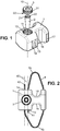
- the implant is composed of a stabilization wedge 1, a locking pin 2, a locking screw 3, and a flexible link 4.
- the stabilization wedge 1 comprises a generally parallelepipedal body with a main axis which, for reasons of clarity of the Figure 1 , is coincident in this figure axis the longitudinal axis 10 of a recess 12 provided in the body and to which we will return later.
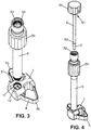
- the Figure 2 is a view of the implant along the longitudinal axis 10, when the implant is placed flat against the vertebrae of the patient (who is lying on the operating table, on his stomach).
- the main axis 10 then coincides with the axis of the posterior approach, that is to say that it is perpendicular to the back of the patient and therefore to the axis of the spine corresponding to the direction of stacking of the vertebrae from the lumbar vertebrae to the cervical vertebrae.
- the body of the stabilization wedge 1 comprises, on a lateral side of the parallelepiped, more particularly on the right on the Figures 1 and 2 , an upper notch or notch 15 and a lower notch or notch 16. These notches are adapted to bear against two vertebrae to be stabilized, and more particularly on the process of the vertebra above by the notch 15 and on the process of the vertebra below through notch 16, respectively. In other words, in the installed position of the implant to ensure the stabilization of two adjacent vertebrae, the spinous processes of these vertebrae are housed in the notches 15 and 16 of the body of the wedge 1.
- the parallelepiped of the body of the wedge 1 has softened (ie rounded) angles, at least on the rear face intended to be covered by the flesh and skin of the patient's back. This limits the risk of inflammation or damage to the back flesh in contact with the implant. Also, this reduces the discomfort or even the pain that the patient may feel when leaning on this part of his back, for example when he is leaning against a support (for example a seat back) or is lying on his back. (for example on a hard surface such as the floor).
- the locking pin 2 can have a cylindrical and conical shape, that is to say have the shape of a cylinder whose diameter of the (circular) section is gradually reduced along its longitudinal axis.
- the longitudinal axis of the pin coincides with the main axis 10 of the body 1 of the wedge and with the longitudinal axis of the recess 12.
- the pin 2 is adapted to cooperate with the recess 12 provided in the body of the wedge 1, for example on the lateral side of the parallelepiped opposite to that where the notches 15 and 16 are located (ie, on the left on the Figures 1 and 2 ).
- the pin 2 and the recess 12 have complementary shapes to each other.
- the pin has the shape of a conical cylinder
- the recess 12 also has the shape of a hollow conical cylinder. with an opening angle equal to that of the pin and an opening diameter slightly larger than said that of the pin.
- the recess opens out (open) at least on the side of the rear face of the wedge 1, and preferably on the side of each of the front and rear faces of the wedge, as shown in the figures.
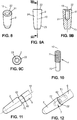
- Figures 5A-5B, 6A-6B, and 7A-7B .
- the diameter of the opening is substantially larger than the largest diameter of the pin, and is constant in an entry zone of the recess on the side of the rear face, through which the pin 2 is intended to enter through its end. tapered.
- its walls In this entry zone of the recess, its walls have an internal thread (internal thread) 11 for the locking screw to which we will return later.
- the length of the entry zone, along the longitudinal axis, is at least equal to the thickness of the locking screw 3.
- the shape of the recess is conical, without tapping (smooth walls) and substantially corresponds to the complementary shape of the pin, that is to say that the shape is conical with the same opening angle as that of the pin but with a slightly larger diameter to be able to receive the pin and the braid as will be explained later.
- the diameter of the recess gradually decreases along its longitudinal axis 10 towards the front.
- the length of the conical part of the recess along the longitudinal axis of the recess is substantially equal to the length of the locking pin 2 along its longitudinal direction.
- Locking screw 3 is also shown in Figure 1 in parallax with the main axis 10 of the body 1 of the wedge and the longitudinal axis of the recess 12.
- the screw 3 has a larger diameter than the largest diameter of the pin. This diameter corresponds to that of the threaded opening zone of the recess 12.
- the screw 3 has an external thread (thread) 31, adapted to cooperate with the internal thread 11 of the recess 12.
- the screw 3 also has a bearing zone 32, facing downwards on the Figure 1 , which can come to bear against a contact area 22 at the rear of the pin 2.
- the bearing area 32 of the screw 3 and / or the contact area 22 of the pin 2 are circular flat surfaces .
- the function of the screw 3 is to lock the position of the pin 2 engaged in the recess 12.
- Another function of the screw is, according to embodiments, to adjust the axial position of the pin in the recess: by turning the pin.
- screw 3 engaged in the recess 12 via their respective threads the screw bears by its surface 32 against a contact surface 22 on the rear side of the pin 2, so that that progresses into the recess 12 along its longitudinal axis, from the rear face of the wedge towards its front face. Details on this adjustment in position will be given later with reference to Figures 5A-5B, 6A-6B, and 7A-7B .
- the flexible tie 4 can be a braid made of a textile material for medical use (non-absorbable), for example of polyethylene terephthalate (PET) or of polyethylene (PE). These materials can be chosen because of their biocompatibility and their high chemical inertness.
- the flexible link 4 encloses the processes in a manner similar to that described in the document EP 2192863 , especially as shown in Figures 3 , 10 and 11A of the publication of this document.
- the flexible link 4 preferably has the shape of a strap (i.e., of a ribbon), with a longitudinal axis and a strap surface extending in said longitudinal direction. It can pass through a passage 17 of the body of the wedge provided in the caudal end of the body of the wedge on the right side thereof, that is to say on the side of the notches 15 and 16 which is opposite to the 'recess 12.
- the passage 17 passes through the body of the wedge 1 perpendicular to the main axis 10 of the body 1 of the wedge. When it is not blocked in movement relative to the wedge, the flexible link 4 can slide in the passage 17.
- the flexible link flexible link 4 can also pass through the recess 12.
- the body of the wedge can have two other passages 13 and 14 passing through the body 1 right through perpendicular to the main axis 10 of the body 1. of the hold. At least one of the passages 13 and 14, and preferably the two passages 13 and 14, pass through the recess 12. In other words, the passages 13 and 14 open into the recess. In the embodiment shown, the two passages 13 and 14 thus pass through the recess 12, but this is not compulsory, and it would be possible that only one of the passages 13 and 14 only passes through the recess 12. When it is not blocked in movement relative to the wedge 1, the flexible link 4 can slide in the passages 13 and 14.
- the flexible link flexible link 4 is inserted manually by the surgeon, for example first through the passage 17. Then the two ends 41 and 42 of the flexible link 4 are in turn inserted into the passages 13 and 14 after having engaged them. above and below the spinous processes of the upper and lower vertebrae, respectively.
- the strap 4 then forms a loop in a plane perpendicular to the main axis 10 of the wedge 1, with at least one and preferably two loops 4a and 4b respectively located on either side of the wedge in said plan.
- These loops 4a and 4b of the textile braid are adapted to come into engagement each with a respective one of the spinous processes of the two vertebrae to be stabilized.
- each of the portions of the strap on the side of its ends 41 and 42 respectively is then blocked in movement relative to the wedge 1.
- This locking is obtained by pinching said portions of strap between the pin and respective portions of the inner wall of the recess 12 facing each other.
- these two end portions of the strap 41a and 42a can pass into the housing 12 provided in the wedge 1 in opposite directions, so as to cross in said housing and form the loops 4a and 4b.
- This embodiment is shown in the Figures.
- the two end portions 41a and 41b of the strap could pass parallel to each other in the passages 13 and 14, and therefore in the recess 12, by means of another form of engagement with the spinous processes of the vertebrae to be stabilized, and also by means of another form of the stabilization wedge.
- the strap would form only one loop, so that two straps would be used, namely one for each of the vertebrae, with the same wedge.
- the ends 41 and 42 of the strap can be reinforced, for example by treatment with an ultrasonic welder, by adding material, or by a titanium end piece, or in any other suitable material, or by any other equivalent means.
- the means for blocking and locking the flexible link 4, which comprise the pin 2 and the screw 3, are placed by the rear face of the stabilization wedge 1. This arrangement allows the surgeon to reduce the size of the incision to the bare minimum, and thus maintain the integrity of the surrounding organic tissues, especially the back muscles.
- the locking pin 2 is inserted into the housing 12, between the two end portions of the flexible link 4.
- the insertion of the pin 2 causes the tightening of the portions of the flexible link 4 between the outer circumferential surface pin 2 and the inner wall facing the recess 12, and stabilizes the flexible link 4. Due to this compression of the flexible link 4, the latter can no longer slide in the passages 13, 14 and 17.
- the screw locking 3 is then engaged in the recess 12, for example by hand (with or without a tool holder), once the conical pin 2 has been fully inserted into the threaded portion 11 of the 'recess 12 as shown in Figures 5A and 5B . This operation is illustrated by the Figures 6A and 6B .
- the function of the screw 3 is to secure (in the axial position) the engagement of the locking pin 2 in the recess 12.
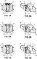
- the method of placing the conical locking pin 2 uses an implant holder 5 and an insertion rod 6, which are shown in Figures 3 and 4 .
- the implant holder 5 is for example a hollow tube, that is to say it has a tubular body having an internal channel 52.
- the channel 52 is for example of constant circular section, with an internal diameter slightly greater than the largest diameter of the locking pin 2.
- an internal thread 53 at the inlet of the channel 52 there may be provided an internal thread 53 at the inlet of the channel 52.
- gripping means which may have the form of a fluted collar 54 surrounding the tube 5 as shown, may be provided. provided on the side of this inlet end of the tube 5.
- the tube 5 can be provided with an external thread 51 which cooperates with the internal thread 11 of the stabilization wedge 1.
- the implant holder 5 can thus be screwed into the stabilization wedge 1, with the internal channel 52 aligned with the longitudinal axis 10 of the recess 2, that is to say in parallax with the recess 12, for the purpose of inserting the locking pin 2 into said recess 12 through the internal channel 52.
- This embodiment of the means for fixing the implant holder 5 to the body 1 of the wedge is also illustrated by the Figure 13 , the description of which will be completed later.
- the fluted collar 54 for gripping the implant holder by the surgeon is preferably close to the end of the tube 5 corresponding to the entrance of the internal channel 52, that is to say the end opposite to that which carries the thread 51 by which the implant holder is fixed to the wedge 1.
- the locking pin 2 can be attached in an easily detachable manner to one end of the insertion rod 6.
- This detachable attachment can be obtained, for example, by means of an elastic connecting piece, the detailed description of which will also be given below.
- the other end of the insertion rod 6 is provided with an external thread 61 below the gripping means such as a splined head 63 as shown.
- This net (not visible at Figure 4 ), which cooperates with the thread 53 of the implant holder 5.
- the insertion rod 6 with the conical pin 2 held in a detachable manner at its end, are introduced into the channel 52 of the implant holder 5, by its end carrying the thread 53.
- the screwing of the insertion rod 6 in the channel 52 of the implant holder 5 drives the conical pin 2 in the housing 12 of the wedge 1.
- This screwing is carried out by the cooperation of the thread 61 of the rod 6 and the tapping 53 of the implant holder 5.
- the implant holder 5 can then be unscrewed from the wedge 1, possibly after unscrewing the insertion rod from the implant holder (not compulsory).
- the pin 2 then automatically detaches from the end of the insertion rod 6 while remaining in place in the unthreaded conical portion of the recess 12.
- the force of the connection of the pin 2 at the end 62 of the insertion rod 2 is calibrated so as to be less than the clamping pressure applied to the pin 2 by the internal wall of the unthreaded conical portion of the recess 12 when the pin is fully engaged therein, and by the force of reaction to the pinching of the flexible link or links.
- the stabilization wedge 1 can be maintained by the surgeon, in position with the loops 4a and 4b of the strap 4 engaged around the spinous processes of the vertebrae to be stabilized , thanks in particular to the gripping zone 54 of the implant holder 5.
- the implant holder therefore serves simultaneously to maintain the stabilization wedge in position against the vertebrae during the critical step of inserting the locking pin of the flexible link 4, but also as an instrument for alignment, guidance and adjustment. insertion of the pin thanks to the rod 6 which slides in the internal channel 52 of the implant holder.
- the locking screw 3 can be engaged in the threaded portion 11 of the recess 12 provided in the wedge, as shown. to the Figure 6A and at the Figure 6B . It will be noted that, at this step, the flexible link is already blocked by the pin 2, by pinching the end portions 41a and 42a against opposite portions of the internal wall of the recess 12, as shown in Figure 5A and at the Figure 5B .
- the screw 3 and the conical pin 2 make it possible to control the tightening pressure exerted on the flexible link 4 without having to resort to a device for measuring the force or the tightening torque.
- the length of the conical pin 2 along its longitudinal direction is calibrated so that its flat contact surface 22 is flush very slightly above the countersink of the threaded hole 11 of the stabilization wedge 1 when it is inserted according to the technique. previously described.
- the flat bearing face 32 of the screw 3 then comes to bear on the counterbore of the threaded hole 11, as well as on the flat contact surface 22 of the conical pin 2, on the rear side, as shown in Figure 7A and at the Figure 7B .
- the screw 3 is screwed into the tapped hole 11 for example by hand, using a screwdriver, for example with a hexagonal head.
- a screwdriver for example with a hexagonal head.
- the clamping screw drives the locking pin 2 further forward in the recess 12, until the flat surface 32 of the clamping screw meets the countersink of the threaded hole 11 which forms a shoulder.
- the axial progression of the conical pin 2 is then blocked by this shoulder, ensuring that the pressure exerted by the conical pin 2 on the flexible link 4 no longer increases even if the surgeon continues to exert a tightening torque on the tightening screw 3 using the screwdriver.
- the screw 3 prevents any movement of the pin 2 which would tend to bring it out of the recess 12, for example under the effect of tensions exerted on the flexible link 4 by the movements of the patient in the gestures of life current. This is the function of locking screw 3.
- the originality of the function of the locking pin according to embodiments of the invention lies in the direction of movement of the pin which is orthogonal to the direction of the bearing force of the pin against the surface of the strap 4 and against the internal wall of the recess 12 provided in the wedge.
- the pin moves in fact only along the axis of the posterior approach, which limits the extent of the surgical intervention zone.
- the solution described in the present description also makes it possible to install a locking screw 3 which provides security (locking in position) of the locking pin 2 of the strap 4, and allows control of the pressure exerted due to the control. the axial displacement of the conical pin 2 in the recess 12. This screw is also placed and tightened only in the direction of the axis of the posterior approach.
- the stabilization wedge 1 can be made of a polymer, for example of polyether ether ketone (PEEK). It can be obtained by machining from a bar or a block of raw material, by injection molded, by 3D printing, or by any other equivalent technique.
- PEEK polyether ether ketone
- the conical locking pin 2 is preferably made of a titanium alloy, chosen for its mechanical strength and its biocompatibility. It can for example be obtained by machining from a bar of raw material.
- the tightening and locking locking screw 3 can also be made of a titanium alloy, for the same reasons and with the same advantages. It can be obtained by machining from a bar of raw material.
- the flexible tie 4 is preferably made of braided textile. As has already been said above, the ends of the flexible link can be stiffened so as to facilitate their gripping and their guidance through the passages 13, 14 and 17 provided in the body of the stabilization wedge 1.
- the pawn has a general frustoconical shape.
- the pin On the more tapered side, called the "front" side, that is to say the side through which the pin is inserted into the recess along the axis of the posterior approach, and that is to say also that which is opposite to the so-called “rear” side which is provided with the support surface 22 already presented, the pin is provided with a rounded end 23. This rounded end facilitates its passage between the strap portions of the strap 4 when they are tensioned in the recess 12 provided in the body 1 of the stabilization wedge.
- the pin 2 comprises a recess 21 extending along its longitudinal axis 10, for example with a diameter equal to 2 mm, which opens out at the rear end 22 of the pin.
- This recess makes it possible to receive a connecting piece, to which we will return later, which has the function of fixing the pin in a detachable manner at the end of the insertion rod 6. But this connection is not obligatory, the pin which can simply be pushed using the insertion rod 6, after its introduction into the internal channel 52 of the implant holder 5, into the recess 12 provided in the body 1 of the wedge.
- the central shaft of the pin 4 has a larger diameter on the side of the rear end 22, for example 4.4 mm, and a smaller diameter, for example 3.9 mm on the side of the front end.
- the dimensions given above are purely illustrative of a nonlimiting embodiment given for the purposes of the present description.
- means may be provided for fixing the pin in a detachable manner to the insertion rod 6, at the end 62 thereof.
- This fixing is not obligatory, as was previously indicated. But it brings the advantage of avoiding the manipulation of the pin alone, which is a small part, above the operating field. This limits the risk associated with the possible fall of the pin, in the implantation site or outside.
- the detachable connection of the pin to the rod also makes it possible to control the progression of the pin 2 along the longitudinal axis of the recess 12 provided in the body of the wedge, by screwing the insertion rod as will be seen below. .
- connection of the pin 2 to the insertion rod 6 can be achieved by an intermediate connecting piece 7, such as the end piece shown in Figure 10 .
- the end piece 7 comprises here, on the one hand, a first threaded end portion 71.
- This part 71 is adapted to cooperate with the tapping of a threaded recess which is provided at the second end 62 of the insertion rod 6 and which extends in the longitudinal direction 10 of said rod 6.
- the end piece 7 also comprises a second end part 72, which may be slightly conical, without being threaded.
- This part 72 is adapted to be forcibly engaged in the recess 21 which is provided at the rear of the locking pin 2 and which was presented above with reference to Figure 8 and to Figures 8, 9B and 9C .
- the slightly conical shape of the second part 72 of the end piece facilitates this force engagement operation.
- the end piece 7 is shown with the first part 71 completely screwed into the recess provided at the end 62 of the insertion rod 6.
- the second part 72 of the end piece is here only partially engaged in the recess 21 provided at the rear 22 of the pin 2.
- the Figure 12 shows the pin 2 after complete completion of its connection to the end 62 of the insertion rod 6.
- the end piece 7 is no longer visible, and has been shown in phantom (ie, in dotted lines) in order to illustrate the way in which the connection of the pin 2 and the rod 6 is carried out.
- the part 71 provides the detachable attachment of the locking pin 2 to the insertion rod 6.
- the tension force which was exerted on the links 4 is released, which then remain wedged against the walls of the recess 12 and therefore retain their tension.
- the implant holder 5 is then unscrewed from the stabilization wedge 1, still with the insertion rod 6 screwed inside the internal channel 51 of the implant holder 5. This exerts a traction on the insertion rod 6 following the longitudinal direction, towards the rear.
- Part 71 of end piece 7 then disengages from pin 2, while the pin remains engaged in the recess 12 provided in the body of the wedge.
- the tip 7 can be made of PE, PET or PEEK, or the like, by machining, molding, 3D printing, or the like. Taking into account the deformation which it may undergo when it is forcibly inserted into the rear of the locking pin 2, the tip is preferably disposable. It is in particular for this reason that it is in the form of an independent part which can be screwed to the end 62 of the rod 6. It can in fact be replaced after each intervention, while the implant holder and the insertion rod are made of stainless steel and can be reused.
- the kit is supplied to the surgeon with the tip 7 already screwed into the insertion rod 6.
- the kit can also be delivered with the pin 2 already coupled to the insertion rod by the 'tip 7.
- the surgeon may prefer to assemble the pin himself on part 72 of the tip, in order to be able to assess the strength of the connection thus produced. The surgeon can thus check that this connection is detachable in the sense that the end piece will easily disengage from the pin when removing the implant holder 5 as described in the previous paragraph.
- FIG. 13 is a sectional view of the insertion rod 2 when it is introduced into the internal channel of the implant holder 5 for placing the pin 2 in the recess 11 provided in the body 1 of the stabilization wedge . It can be seen in this figure, in which the same elements as in the other figures bear the same references, that the implant holder 5 is fixed to the stabilization wedge 1 and that a flexible link 4 (strap) passes through the recess 12.
- the implant holder is provided with an internal thread 53 at the other of its ends, on the side of a free entry of the internal channel 52, that is to say the side opposite to the wedge 1 when the holder- implant is fixed to said wedge 1.
- the term “entry” is used here with reference to the fact that the pin is inserted into the internal channel 52 of the implant holder through this threaded end 53 of the rod.
- the insertion rod 6 is provided with a complementary thread 61, at its end 62 to cooperate with the internal thread 53.
- the insertion and then the screwing of the insertion rod 6 into the internal channel 52 of the door -implant 5 advances the conical pin 2 in the recess 12 provided in the body 1 of the stabilization wedge, in the direction of the longitudinal axis 10 of said recess (which then coincides with the longitudinal axis of the internal channel 52) .
- the progression of the pin in this direction is well controlled by controlling the rotation of the insertion rod. This operation can be performed by the surgeon by holding the implant holder 5 in one hand via the gripping part 54 of said implant holder, and turning the insertion rod 6 with the other hand via the gripping part 64 of the implant holder. said rod.
- the insertion of the pin along the longitudinal axis of the recess 12 is advantageous for the insertion of the pin along the longitudinal axis of the recess 12 to be carried out by rotating the pin around said axis.
- the helical movement of the pin which is thus obtained facilitates its insertion into the recess and limits the stress on the flexible links that it comes from. wedge against the inner wall of the recess.
- the friction of the pin 2 on the surface of the flexible links, or strap surface is distributed between a component orthogonal to the longitudinal direction of the strap and a component parallel to said longitudinal direction. This also limits the risk of the strap folding back on itself in the direction orthogonal to the longitudinal axis of the strap.
- the locking pin is fully inserted into the recess 12 provided in the stabilization wedge. This result is guaranteed by the design of the various elements of the kit, in particular the axial length of the pin and that of the insertion rod, and the axial length of the threads 11 and 53.
- the implant holder can then be separated from the stabilization wedge, by unscrewing it from the threaded portion 11 of the recess 12 provided in said wedge, leaving the pin 2 in place in said recess, as has been said. upper.
- the Figure 14 is a three-dimensional view of the stabilization wedge with the locking pin 2 engaged in the recess, after separation of the implant holder 5 from the stabilization wedge 1, and before placing the locking screw 3. It is note again that the locking of the flexible link 4 is effective with the conical pin 2 alone, the locking screw 3 being only an additional safety measure.
- the same threaded part 11 at the entrance of the recess 12 in the stabilization wedge is used again, this time for the positioning of the locking screw 3.
- the thread 11 is used successively.
- the temporary fixing of the implant holder 5 on the wedge 1 during the operation then the installation of the locking screw 3 which permanently secures the position of the pin 2 in the recess 12.
- the design of the wedge according to the embodiments described is therefore particularly simple. A reduced number of parts and elements allow the positioning of the locking pin by manual operations which are performed by the surgeon along the axis of the posterior approach only.
- the fixing of the implant holder 5 on the wedge 1 can be carried out in a manner different from the screwing described above.
- this fixing can be obtained by a mechanism of the “bayonet” type, or by any other form of latching.
- connection between the pin 2 and the insertion rod 6 can be obtained by means of a connecting piece 7 which may differ, in its embodiment, from the tip described above with reference to Figure 10 .
- the part 7 can for example be an elastic connecting part. It may for example be a cylinder or sleeve of deformable elastic material, for example of elastomeric material. This part 7 cooperates with the recess 21 made at the rear 22 of the locking pin 2, and with an unthreaded recess provided at the first end 62 of the insertion rod 6.
- the sleeve When a first end part of the sleeve is pressed into the first recess above, and as the second end portion of the sleeve is driven into the second recess above, the sleeve provides the detachable attachment of said locking pin to the insertion rod.
- the diameter of the sleeve 7 is slightly greater than the diameter of the recess 21 which is provided in the pin 2.
- the sleeve 7 can be forced into the channel 21 through the rear end 22 of the pin 2. , by playing on its elasticity. Part of the sleeve is left outside the channel 21, and protrudes from the end 22 of the pin towards the rear. The surgeon then pushes this free end of the sleeve 7, the other end of which is and remains engaged in the pin 2, inside the recess at the end 62 of the insertion rod.
- the diameter of this recess is slightly less than the diameter of the part 7. In other words, the rod 6 is thus pushed over the sleeve 7, and this until the edge of the end 62 of the rod comes in. contact with the rear edge 22 of the locking pin 2.
- the order of the two operations above can be reversed.
Landscapes
- Health & Medical Sciences (AREA)
- Orthopedic Medicine & Surgery (AREA)
- Life Sciences & Earth Sciences (AREA)
- Surgery (AREA)
- Neurology (AREA)
- Engineering & Computer Science (AREA)
- Biomedical Technology (AREA)
- General Health & Medical Sciences (AREA)
- Veterinary Medicine (AREA)
- Heart & Thoracic Surgery (AREA)
- Public Health (AREA)
- Animal Behavior & Ethology (AREA)
- Molecular Biology (AREA)
- Medical Informatics (AREA)
- Nuclear Medicine, Radiotherapy & Molecular Imaging (AREA)
- Transplantation (AREA)
- Cardiology (AREA)
- Oral & Maxillofacial Surgery (AREA)
- Vascular Medicine (AREA)
- Physical Education & Sports Medicine (AREA)
- Prostheses (AREA)
- Surgical Instruments (AREA)
Claims (10)
- Chirurgie-Kit bestehend aus:- einem Zwischenwirbel-Implantat mit:- einem Stabilisierungskeil (1), der dazu ausgebildet ist, wenigstens zwei benachbarte Wirbel durch Einfügung zwischen Dornfortsätzen der Wirbel zu stabilisieren, mit einem im wesentlichen parallelepipedischen Körper, der eine vorbestimmte Hauptachse (10) aufweist und in dem eine Aussparung (12) vorgesehen ist, die eine bestimmte Längsachse parallel zur Hauptachse des Körpers des Stabilisierungskeils aufweist; und- wenigstens einem Riemen (4), der eine flexible Verbindung zur Befestigung des Stabilisierungskeils an den Dornfortsätzen der zu stabilisierenden Wirbel bildet, wobei der Riemen einen ersten und einen zweiten Abschnitt (41a, 42a) umfasst, die jeweils eines der gegenüberliegenden Enden (41, 42) des Riemens aufweisen; sowie- einem Implantathalter (5) mit einem länglichen Körper entlang einer vorbestimmten Längsachse und mit einem ersten Ende (51) und einem zweiten Ende (53), und mit an dem ersten Ende (51) vorgesehen Befestigungsmitteln, welche dazu ausgebildet sind, mit zugehörigen Mitteln, die an dem Körper des Implantatstabilisierungskeils vorgesehen sind, zusammenzuwirken, um den Implantathalter an dem Körper des Stabilisierungskeils derart zu befestigen, dass der längliche Körper des Implantathalters in Parallaxe mit der Aussparung (12) ist;wobei :- die im Körper des Stabilisierungskeils vorgesehene Aussparung eine Innenwand umfasst, die sich parallel zur Längsachse der Aussparung erstreckt, und eine vorbestimmte Form hat; und- wenigstens der erste Riemenabschnitt in der Aussparung senkrecht zur Längsachse der Aussparung verlaufen kann;- das Zwischenwirbelimplantat ferner einen Verriegelungsstift (2) mit einer vorbestimmten Längsachse und einer vorbestimmten Form aufweist, die im Wesentlichen komplementär zu der Form der in dem Körper des Stabilisierungskeils vorgesehenen Ausnehmung ist, um mit dem Stabilisierungskeil durch Bewegung in der Ausnehmung in Richtung der Längsachse der Ausnehmung in Eingriff zu kommen, um so den sich bewegenden Riemen relativ zu dem Stabilisierungskeil durch Einklemmen des Riemenabschnitts zwischen dem Verriegelungsstift und der Innenwand der Ausnehmung zu verriegeln; und- der langgestreckte Körper des Implantathalters rohrförmig ist, mit einem inneren Kanal (52), der sich entlang der Längsachse des langgestreckten Körpers des Implantathalters erstreckt und einen Innendurchmesser aufweist, der etwas größer ist als der größte Durchmesser des Verriegelungsstiftes (2) des Implantats, um das Einführen und Führen des Verriegelungsstiftes durch den inneren Kanal in die im Körper des Stabilisierungskeils vorgesehene Aussparung (12) in Richtung der Längsachse der Aussparung zu ermöglichen, wenn der Implantathalter an dem Stabilisierungskeil befestigt ist.
- Chirurgie-Kit nach Anspruch 1, wobei:- die in dem Körper des Stabilisierungskeils vorgesehene Aussparung einen mit einem Innengewinde versehenen Eintrittsbereich (11) aufweist, und- der rohrförmige Körper des Implantathalters an seinem ersten Ende (51) ein Außengewinde aufweist, das mit dem Innengewinde des Eintrittsbereichs der Aussparung für die Schraubbefestigung des Implantathalters an dem Stabilisierungskeil (1) zusammenwirkt.
- Chirurgie-Kit nach Anspruch 1 oder Anspruch 2, welches weiterhin umfasst:- eine Stange (6) zum Einführen des Verriegelungsstifts (2) mit einem ersten Ende (61) und einem zweiten Ende (62), welche dazu ausgebildet ist, in dem inneren Kanal (52) des rohrförmigen Körpers des Implantathalters (5) zu gleiten, zum Einführen und Führen des Verriegelungsstifts (2) durch den inneren Kanal (52) des Implantathalters (5) bis in die in dem Körper des Stabilisierungskeils vorgesehene Aussparung (12) einzuführen und zu führen.
- Chirurgie-Kit nach Anspruch 3, welches ferner ein Verbindungsstück (7) zur lösbaren Befestigung des Verriegelungsstiftes (2) am zweiten Ende (62) der Einführstange (6) aufweist.
- Chirurgie-Kit nach Anspruch 4, wobei:- der Verriegelungsstift (2) an der Rückseite (22) eine Aussparung (21) aufweist, die sich in Längsrichtung (10) des Stiftes erstreckt,- das zweite Ende (62) der Einführstange (6) eine Aussparung mit Innengewinde aufweist, die sich in Längsrichtung der Stange (6) erstreckt, und- das Verbindungsstück (7) ein Endstück ist, das einerseits einen ersten mit Außengewinde versehenen Endabschnitt (71) aufweist, der dazu ausgebildet ist, mit dem Innengewinde der am zweiten Ende (62) der Einführstange vorgesehenen Aussparung zusammenzuwirken, und andererseits einen zweiten konischen Endabschnitt (72) aufweist, der dazu ausgebildet ist, unter Kraftaufwand in die am hinteren Ende des Verriegelungsstifts (2) vorgesehene Aussparung einzugreifen, um die lösbare Befestigung des Verriegelungsstifts an der Einführstange zu erreichen.
- Chirurgie-Kit nach einem der Ansprüche 1 bis 5, wobei der Implantathalter (5) an seinem zweiten Ende (53) mit einem Innengewinde an der Seite eines freien Zugangs zu dem Innenkanal (52) versehen ist, wenn der Implantathalter an dem Stabilisierungskeil befestigt ist, und wobei die Einführstange (6) an ihrem ersten Ende (61) mit einem Außengewinde zum Zusammenwirken mit dem Innengewinde versehen ist, so dass das Einführen und dann das Einschrauben der Einführstange (6) in den inneren Kanal (52) des Implantathalters (5) den konischen Stift (2) in die im Körper des Stabilisierungskeils vorgesehene Aussparung (12) in Richtung der Längsachse der genannten Aussparung treibt.
- Chirurgie-Kit nach einem der Ansprüche 1 bis 6, wobei der Riemen eine vorbestimmte Längsrichtung und eine vorbestimmte Riemenoberfläche aufweist, und wobei der Verriegelungsstift durch Verschieben innerhalb der im Körper des Stabilisierungskeils vorgesehenen Ausnehmung derart in den Stabilisierungskeil eingreifen kann, dass die Längsachse des Verriegelungsstiftes:- erstens dann mit der Längsachse der Aussparung zusammenfällt,- zweitens senkrecht zur Längsachse des Riemenabschnitts innerhalb der Aussparung steht, und- drittens parallel zur Oberfläche des ersten Riemenabschnitts innerhalb der Aussparung ist.
- Chirurgie-Kit nach einem der Ansprüche 1 bis 6, wobei:- der Riemen eine vorbestimmte Längsrichtung und eine vorbestimmte Riemenoberfläche aufweist;- sowohl der erste als auch der zweite Riemenabschnitt in der im Stabilisierungskeil vorgesehenen Aufnahme verlaufen kann, so dass der Riemen in einer zur Hauptachse des Keils senkrechten Ebene wenigstens eine Schlaufe bildet, wobei wenigstens eine Rundschnur zum Eingriff in einen der Dornfortsätze von zwei zu stabilisierenden Wirbeln ausgebildet ist; und- der Verriegelungsstift mit dem Stabilisierungskeil in Richtung der Hauptachse des Körpers des Keils zwischen dem ersten und dem zweiten Riemenabschnitt (41a, 42a) innerhalb der Aussparung in Eingriff kommen kann, so dass die Längsachse des Stiftes:und ferner derart, dass jeder aus erstem und zweitem Riemenabschnitt gegen eine Bewegung relativ zum Stabilisierungskeil verriegelt wird, indem der Riemenabschnitt zwischen dem Verriegelungsstift und jeweiligen einander zugewandten Teilen der Innenwand der Aussparung eingeklemmt wird.- erstens dann mit der Längsachse der Aussparung zusammenfällt;- zweitens senkrecht zur Längsachse jedes der beiden Riemenabschnitte innerhalb der Aussparung steht; und- drittens parallel zur Oberfläche des ersten und des zweiten Riemenabschnitts innerhalb der Aussparung ist,
- Chirurgie-Kit nach Anspruch 8, wobei der erste und der zweite Teil des Riemens durch die im Körper des Stabilisierungskeils vorgesehene Aufnahme in entgegengesetzten Richtungen hindurch verlaufen können, so dass sie sich in der genannten Aufnahme kreuzen und der Riemen in einer zur Hauptachse des Keils senkrechten Ebene eine Schlaufe bildet, wobei zwei Rundschnüre jeweils auf beiden Seiten des Stabilisierungskeils in der genannten Ebene angeordnet und so ausgebildet sind, dass sie mit jeweils einem der Dornfortsätze zweier benachbarter zu stabilisierender Wirbel in Eingriff kommen.
- Chirurgie-Kit nach einem der vorhergehenden Ansprüche, welches ferner eine Schraube mit dem gleichen Durchmesser umfasst wie der Durchmesser des Eintrittsbereichs der im Körper des Stabilisierungskeils vorgesehenen Aussparung, mit einem Außengewinde, das dazu ausgebildet ist, mit dem Innengewinde des Eintrittsbereichs zusammenzuwirken, und mit einem Anlagebereich (32), der dazu ausgebildet ist, an einem Kontaktbereich an der Rückseite (22) des Verriegelungsstifts (2) anzuliegen, um in der axialen Position den Eingriff des Verriegelungsstifts in der im Stabilisierungskeil vorgesehenen Aussparung (12) und somit die Verriegelung des Riemens zu verriegeln.
Priority Applications (1)
| Application Number | Priority Date | Filing Date | Title |
|---|---|---|---|
| PL17710325T PL3416574T3 (pl) | 2016-02-15 | 2017-02-15 | Implant międzykręgowy do dynamicznej stabilizacji i jego narzędzie pozycjonujące |
Applications Claiming Priority (2)
| Application Number | Priority Date | Filing Date | Title |
|---|---|---|---|
| FR1651206A FR3047658B1 (fr) | 2016-02-15 | 2016-02-15 | Implant intervertebral de stabilisation dynamique et son outil de positionnement |
| PCT/FR2017/050345 WO2017140983A1 (fr) | 2016-02-15 | 2017-02-15 | Implant intervertebral de stabilisation dynamique et son outil de positionnement |
Publications (2)
| Publication Number | Publication Date |
|---|---|
| EP3416574A1 EP3416574A1 (de) | 2018-12-26 |
| EP3416574B1 true EP3416574B1 (de) | 2020-09-09 |
Family
ID=56511641
Family Applications (1)
| Application Number | Title | Priority Date | Filing Date |
|---|---|---|---|
| EP17710325.6A Active EP3416574B1 (de) | 2016-02-15 | 2017-02-15 | Dynamisch stabilisierendes zwischenwirbelimplantat und werkzeug zu dessen positionierung |
Country Status (13)
| Country | Link |
|---|---|
| US (1) | US10932824B2 (de) |
| EP (1) | EP3416574B1 (de) |
| JP (1) | JP6896767B2 (de) |
| KR (1) | KR102711980B1 (de) |
| CN (1) | CN109069193B (de) |
| AU (1) | AU2017219961B2 (de) |
| BR (1) | BR112018016556A2 (de) |
| ES (1) | ES2835098T3 (de) |
| FR (1) | FR3047658B1 (de) |
| PL (1) | PL3416574T3 (de) |
| SG (1) | SG11201809072UA (de) |
| WO (1) | WO2017140983A1 (de) |
| ZA (1) | ZA201808526B (de) |
Families Citing this family (2)
| Publication number | Priority date | Publication date | Assignee | Title |
|---|---|---|---|---|
| AU2019280691B2 (en) * | 2018-06-05 | 2024-10-31 | Vb Spine Us Opco Llc | Band clamp, band clamp assembly |
| FR3146397B1 (fr) * | 2023-03-07 | 2025-03-07 | Backbone | Implant vertebral de stabilisation dynamique |
Family Cites Families (16)
| Publication number | Priority date | Publication date | Assignee | Title |
|---|---|---|---|---|
| US5496318A (en) * | 1993-01-08 | 1996-03-05 | Advanced Spine Fixation Systems, Inc. | Interspinous segmental spine fixation device |
| US6099527A (en) * | 1998-04-30 | 2000-08-08 | Spinal Concepts, Inc. | Bone protector and method |
| FR2799640B1 (fr) * | 1999-10-15 | 2002-01-25 | Spine Next Sa | Implant intervetebral |
| FR2818530B1 (fr) * | 2000-12-22 | 2003-10-31 | Spine Next Sa | Implant intervertebral a cale deformable |
| US9539012B2 (en) * | 2002-10-30 | 2017-01-10 | Zimmer Spine, Inc. | Spinal stabilization systems with quick-connect sleeve assemblies for use in surgical procedures |
| US7473255B2 (en) * | 2006-02-08 | 2009-01-06 | Synthes (U.S.A.) | Transbuccal plate holding cannula |
| EP2182864B1 (de) * | 2007-06-22 | 2016-06-08 | Empirical Spine, Inc. | Vorrichtungen zur kontrollierten flexionsbegrenzung von wirbelsäulensegmenten |
| FR2921248A1 (fr) * | 2007-09-25 | 2009-03-27 | Abbott Spine Sa | Dispositif de serrage de deux portions d'une tresse et implant intervertebral comprenant une cale, une tresse et un tel dispositif de serrage |
| WO2009141393A1 (en) * | 2008-05-20 | 2009-11-26 | Zimmer Spine | System for stabilizing at least three vertebrae |
| EP2138122A1 (de) * | 2008-06-25 | 2009-12-30 | Abbott Spine | Stabilisationssystem zwischen dem Kreuzbein und einem Lendenwirbel |
| EP2184023B1 (de) * | 2008-11-07 | 2016-06-29 | Zimmer Spine | Operationsinstrument zur Spannung eines flexiblen Elements |
| GB0922614D0 (en) * | 2009-12-23 | 2010-02-10 | Butterfield Forbes | Device |
| EP2351534B1 (de) * | 2010-02-01 | 2012-08-22 | Zimmer Spine | Zwischenwirbelvorrichtung |
| EP2677949A1 (de) * | 2011-02-22 | 2014-01-01 | Simpirica Spine, Inc. | Verfahren für eine drahtumschlingung mit dornfortsätzen zum halten von knochenimplantaten |
| US10238433B2 (en) * | 2011-07-21 | 2019-03-26 | Zimmer Spine | Fixing device |
| FR3047657B1 (fr) * | 2016-02-15 | 2018-02-09 | Backbone | Implant intervertebral de stabilisation dynamique et kit chirurgical l'incorporant |
-
2016
- 2016-02-15 FR FR1651206A patent/FR3047658B1/fr active Active
-
2017
- 2017-02-15 CN CN201780023825.7A patent/CN109069193B/zh active Active
- 2017-02-15 BR BR112018016556-5A patent/BR112018016556A2/pt not_active IP Right Cessation
- 2017-02-15 KR KR1020187026896A patent/KR102711980B1/ko active Active
- 2017-02-15 WO PCT/FR2017/050345 patent/WO2017140983A1/fr not_active Ceased
- 2017-02-15 PL PL17710325T patent/PL3416574T3/pl unknown
- 2017-02-15 ES ES17710325T patent/ES2835098T3/es active Active
- 2017-02-15 JP JP2018561089A patent/JP6896767B2/ja active Active
- 2017-02-15 EP EP17710325.6A patent/EP3416574B1/de active Active
- 2017-02-15 AU AU2017219961A patent/AU2017219961B2/en active Active
- 2017-02-15 US US15/999,441 patent/US10932824B2/en active Active
- 2017-02-15 SG SG11201809072UA patent/SG11201809072UA/en unknown
-
2018
- 2018-12-18 ZA ZA2018/08526A patent/ZA201808526B/en unknown
Non-Patent Citations (1)
| Title |
|---|
| None * |
Also Published As
| Publication number | Publication date |
|---|---|
| FR3047658A1 (fr) | 2017-08-18 |
| ES2835098T3 (es) | 2021-06-21 |
| KR102711980B1 (ko) | 2024-10-02 |
| SG11201809072UA (en) | 2018-11-29 |
| PL3416574T3 (pl) | 2021-04-19 |
| CN109069193A (zh) | 2018-12-21 |
| AU2017219961B2 (en) | 2021-07-22 |
| BR112018016556A2 (pt) | 2018-12-26 |
| WO2017140983A1 (fr) | 2017-08-24 |
| ZA201808526B (en) | 2020-02-26 |
| CN109069193B (zh) | 2021-07-23 |
| EP3416574A1 (de) | 2018-12-26 |
| US20200107864A1 (en) | 2020-04-09 |
| AU2017219961A1 (en) | 2018-10-04 |
| KR20180134861A (ko) | 2018-12-19 |
| JP2019504744A (ja) | 2019-02-21 |
| JP6896767B2 (ja) | 2021-06-30 |
| US10932824B2 (en) | 2021-03-02 |
| FR3047658B1 (fr) | 2018-02-09 |
Similar Documents
| Publication | Publication Date | Title |
|---|---|---|
| EP3416576B1 (de) | Dynamisch stabilisierendes wirbelsäulenimplantat und chirurgisches kit damit | |
| EP1926444B1 (de) | Wirbelfixationssystem | |
| WO2015107311A1 (fr) | Instrument chirurgical pour la pose d'une agrafe d'ostéosynthèse | |
| FR2970636A1 (fr) | Dispositif de forage pour la realisation d'un canal osseux a profil courbe a l'interieur du corps d'une vertebre | |
| WO2013150232A1 (fr) | Kit d'intrumentation d'osteosynthèse rachidienne | |
| WO2010061124A1 (fr) | Dispositif d'aide a la pose d'implants dentaires | |
| FR2937531A1 (fr) | Systeme d'osteosynthese rachidienne | |
| EP3310282B1 (de) | Implantat zur fixation von knochenelementen | |
| EP3772346B1 (de) | Schädeldeckenfixierer | |
| EP3416574B1 (de) | Dynamisch stabilisierendes zwischenwirbelimplantat und werkzeug zu dessen positionierung | |
| WO2013178940A1 (fr) | Dispositif rachidien comprenant des moyens d'accroche réversible | |
| FR3028407A1 (fr) | Dispositif de guidage securise | |
| EP3344171A1 (de) | Wirbelimplantat, verfahren zur platzierung solch eines implantats und werkzeug zur platzierung des implantats | |
| WO2018024617A1 (fr) | Implant deployable | |
| FR2930720A1 (fr) | Element de liaison entre un element longitudinal d'un dispositif d'osteosynthese vertebrale et une vertebre, dispositif d'osteosynthese vertebrale le comprenant et outil pour sa pose | |
| EP3668429B1 (de) | Anordnung zur unterstützung der positionierung eines zwischenwirbelimplantats und diesen enthaltendes chirurgisches kit | |
| WO2014068210A1 (fr) | Dispositif de resurfaçage phalangien et métatarsien ou métacarpien et instrumentation pour la mise en place de tels dispositifs | |
| FR2929829A1 (fr) | Systeme de liaison entre un implant remplacant un corps vertebral et une instrumentation de fixation | |
| FR3034644A1 (fr) | Element d'ancrage osseux pour appareillage d'osteosynthese, et appareillage d'osteosynthese le comportant | |
| FR3044544A1 (fr) | Dispositif pour inserer une cale entre deux portions d'os | |
| FR2890849A1 (fr) | Systeme de fixation vertebrale. | |
| WO2010133657A1 (fr) | Outil pour la prehension d'un implant sous forme de tige dans une intervention chirurgicale minimalement invasive | |
| EP2459083A1 (de) | Chirurgisches hilfssystem für transversale rekonstruktion des kniekreuzbandes |
Legal Events
| Date | Code | Title | Description |
|---|---|---|---|
| STAA | Information on the status of an ep patent application or granted ep patent |
Free format text: STATUS: UNKNOWN |
|
| STAA | Information on the status of an ep patent application or granted ep patent |
Free format text: STATUS: THE INTERNATIONAL PUBLICATION HAS BEEN MADE |
|
| PUAI | Public reference made under article 153(3) epc to a published international application that has entered the european phase |
Free format text: ORIGINAL CODE: 0009012 |
|
| STAA | Information on the status of an ep patent application or granted ep patent |
Free format text: STATUS: REQUEST FOR EXAMINATION WAS MADE |
|
| 17P | Request for examination filed |
Effective date: 20180914 |
|
| AK | Designated contracting states |
Kind code of ref document: A1 Designated state(s): AL AT BE BG CH CY CZ DE DK EE ES FI FR GB GR HR HU IE IS IT LI LT LU LV MC MK MT NL NO PL PT RO RS SE SI SK SM TR |
|
| AX | Request for extension of the european patent |
Extension state: BA ME |
|
| DAV | Request for validation of the european patent (deleted) | ||
| DAX | Request for extension of the european patent (deleted) | ||
| GRAP | Despatch of communication of intention to grant a patent |
Free format text: ORIGINAL CODE: EPIDOSNIGR1 |
|
| STAA | Information on the status of an ep patent application or granted ep patent |
Free format text: STATUS: GRANT OF PATENT IS INTENDED |
|
| INTG | Intention to grant announced |
Effective date: 20191125 |
|
| GRAJ | Information related to disapproval of communication of intention to grant by the applicant or resumption of examination proceedings by the epo deleted |
Free format text: ORIGINAL CODE: EPIDOSDIGR1 |
|
| STAA | Information on the status of an ep patent application or granted ep patent |
Free format text: STATUS: REQUEST FOR EXAMINATION WAS MADE |
|
| INTC | Intention to grant announced (deleted) | ||
| GRAJ | Information related to disapproval of communication of intention to grant by the applicant or resumption of examination proceedings by the epo deleted |
Free format text: ORIGINAL CODE: EPIDOSDIGR1 |
|
| GRAP | Despatch of communication of intention to grant a patent |
Free format text: ORIGINAL CODE: EPIDOSNIGR1 |
|
| GRAR | Information related to intention to grant a patent recorded |
Free format text: ORIGINAL CODE: EPIDOSNIGR71 |
|
| GRAS | Grant fee paid |
Free format text: ORIGINAL CODE: EPIDOSNIGR3 |
|
| STAA | Information on the status of an ep patent application or granted ep patent |
Free format text: STATUS: GRANT OF PATENT IS INTENDED |
|
| GRAA | (expected) grant |
Free format text: ORIGINAL CODE: 0009210 |
|
| STAA | Information on the status of an ep patent application or granted ep patent |
Free format text: STATUS: THE PATENT HAS BEEN GRANTED |
|
| AK | Designated contracting states |
Kind code of ref document: B1 Designated state(s): AL AT BE BG CH CY CZ DE DK EE ES FI FR GB GR HR HU IE IS IT LI LT LU LV MC MK MT NL NO PL PT RO RS SE SI SK SM TR |
|
| INTG | Intention to grant announced |
Effective date: 20200804 |
|
| REG | Reference to a national code |
Ref country code: GB Ref legal event code: FG4D Free format text: NOT ENGLISH |
|
| REG | Reference to a national code |
Ref country code: AT Ref legal event code: REF Ref document number: 1310587 Country of ref document: AT Kind code of ref document: T Effective date: 20200915 Ref country code: CH Ref legal event code: EP |
|
| REG | Reference to a national code |
Ref country code: DE Ref legal event code: R096 Ref document number: 602017023262 Country of ref document: DE |
|
| REG | Reference to a national code |
Ref country code: IE Ref legal event code: FG4D Free format text: LANGUAGE OF EP DOCUMENT: FRENCH |
|
| REG | Reference to a national code |
Ref country code: CH Ref legal event code: NV Representative=s name: VALIPAT S.A. C/O BOVARD SA NEUCHATEL, CH |
|
| REG | Reference to a national code |
Ref country code: LT Ref legal event code: MG4D |
|
| PG25 | Lapsed in a contracting state [announced via postgrant information from national office to epo] |
Ref country code: GR Free format text: LAPSE BECAUSE OF FAILURE TO SUBMIT A TRANSLATION OF THE DESCRIPTION OR TO PAY THE FEE WITHIN THE PRESCRIBED TIME-LIMIT Effective date: 20201210 Ref country code: LT Free format text: LAPSE BECAUSE OF FAILURE TO SUBMIT A TRANSLATION OF THE DESCRIPTION OR TO PAY THE FEE WITHIN THE PRESCRIBED TIME-LIMIT Effective date: 20200909 Ref country code: FI Free format text: LAPSE BECAUSE OF FAILURE TO SUBMIT A TRANSLATION OF THE DESCRIPTION OR TO PAY THE FEE WITHIN THE PRESCRIBED TIME-LIMIT Effective date: 20200909 Ref country code: NO Free format text: LAPSE BECAUSE OF FAILURE TO SUBMIT A TRANSLATION OF THE DESCRIPTION OR TO PAY THE FEE WITHIN THE PRESCRIBED TIME-LIMIT Effective date: 20201209 Ref country code: HR Free format text: LAPSE BECAUSE OF FAILURE TO SUBMIT A TRANSLATION OF THE DESCRIPTION OR TO PAY THE FEE WITHIN THE PRESCRIBED TIME-LIMIT Effective date: 20200909 Ref country code: BG Free format text: LAPSE BECAUSE OF FAILURE TO SUBMIT A TRANSLATION OF THE DESCRIPTION OR TO PAY THE FEE WITHIN THE PRESCRIBED TIME-LIMIT Effective date: 20201209 Ref country code: SE Free format text: LAPSE BECAUSE OF FAILURE TO SUBMIT A TRANSLATION OF THE DESCRIPTION OR TO PAY THE FEE WITHIN THE PRESCRIBED TIME-LIMIT Effective date: 20200909 |
|
| REG | Reference to a national code |
Ref country code: AT Ref legal event code: MK05 Ref document number: 1310587 Country of ref document: AT Kind code of ref document: T Effective date: 20200909 |
|
| REG | Reference to a national code |
Ref country code: NL Ref legal event code: MP Effective date: 20200909 |
|
| PG25 | Lapsed in a contracting state [announced via postgrant information from national office to epo] |
Ref country code: RS Free format text: LAPSE BECAUSE OF FAILURE TO SUBMIT A TRANSLATION OF THE DESCRIPTION OR TO PAY THE FEE WITHIN THE PRESCRIBED TIME-LIMIT Effective date: 20200909 Ref country code: LV Free format text: LAPSE BECAUSE OF FAILURE TO SUBMIT A TRANSLATION OF THE DESCRIPTION OR TO PAY THE FEE WITHIN THE PRESCRIBED TIME-LIMIT Effective date: 20200909 |
|
| PG25 | Lapsed in a contracting state [announced via postgrant information from national office to epo] |
Ref country code: SM Free format text: LAPSE BECAUSE OF FAILURE TO SUBMIT A TRANSLATION OF THE DESCRIPTION OR TO PAY THE FEE WITHIN THE PRESCRIBED TIME-LIMIT Effective date: 20200909 Ref country code: RO Free format text: LAPSE BECAUSE OF FAILURE TO SUBMIT A TRANSLATION OF THE DESCRIPTION OR TO PAY THE FEE WITHIN THE PRESCRIBED TIME-LIMIT Effective date: 20200909 Ref country code: PT Free format text: LAPSE BECAUSE OF FAILURE TO SUBMIT A TRANSLATION OF THE DESCRIPTION OR TO PAY THE FEE WITHIN THE PRESCRIBED TIME-LIMIT Effective date: 20210111 Ref country code: CZ Free format text: LAPSE BECAUSE OF FAILURE TO SUBMIT A TRANSLATION OF THE DESCRIPTION OR TO PAY THE FEE WITHIN THE PRESCRIBED TIME-LIMIT Effective date: 20200909 Ref country code: EE Free format text: LAPSE BECAUSE OF FAILURE TO SUBMIT A TRANSLATION OF THE DESCRIPTION OR TO PAY THE FEE WITHIN THE PRESCRIBED TIME-LIMIT Effective date: 20200909 |
|
| PG25 | Lapsed in a contracting state [announced via postgrant information from national office to epo] |
Ref country code: AT Free format text: LAPSE BECAUSE OF FAILURE TO SUBMIT A TRANSLATION OF THE DESCRIPTION OR TO PAY THE FEE WITHIN THE PRESCRIBED TIME-LIMIT Effective date: 20200909 Ref country code: AL Free format text: LAPSE BECAUSE OF FAILURE TO SUBMIT A TRANSLATION OF THE DESCRIPTION OR TO PAY THE FEE WITHIN THE PRESCRIBED TIME-LIMIT Effective date: 20200909 Ref country code: IS Free format text: LAPSE BECAUSE OF FAILURE TO SUBMIT A TRANSLATION OF THE DESCRIPTION OR TO PAY THE FEE WITHIN THE PRESCRIBED TIME-LIMIT Effective date: 20210109 |
|
| REG | Reference to a national code |
Ref country code: DE Ref legal event code: R097 Ref document number: 602017023262 Country of ref document: DE |
|
| REG | Reference to a national code |
Ref country code: ES Ref legal event code: FG2A Ref document number: 2835098 Country of ref document: ES Kind code of ref document: T3 Effective date: 20210621 |
|
| PG25 | Lapsed in a contracting state [announced via postgrant information from national office to epo] |
Ref country code: SK Free format text: LAPSE BECAUSE OF FAILURE TO SUBMIT A TRANSLATION OF THE DESCRIPTION OR TO PAY THE FEE WITHIN THE PRESCRIBED TIME-LIMIT Effective date: 20200909 |
|
| PLBE | No opposition filed within time limit |
Free format text: ORIGINAL CODE: 0009261 |
|
| STAA | Information on the status of an ep patent application or granted ep patent |
Free format text: STATUS: NO OPPOSITION FILED WITHIN TIME LIMIT |
|
| 26N | No opposition filed |
Effective date: 20210610 |
|
| PG25 | Lapsed in a contracting state [announced via postgrant information from national office to epo] |
Ref country code: SI Free format text: LAPSE BECAUSE OF FAILURE TO SUBMIT A TRANSLATION OF THE DESCRIPTION OR TO PAY THE FEE WITHIN THE PRESCRIBED TIME-LIMIT Effective date: 20200909 Ref country code: DK Free format text: LAPSE BECAUSE OF FAILURE TO SUBMIT A TRANSLATION OF THE DESCRIPTION OR TO PAY THE FEE WITHIN THE PRESCRIBED TIME-LIMIT Effective date: 20200909 |
|
| PG25 | Lapsed in a contracting state [announced via postgrant information from national office to epo] |
Ref country code: MC Free format text: LAPSE BECAUSE OF FAILURE TO SUBMIT A TRANSLATION OF THE DESCRIPTION OR TO PAY THE FEE WITHIN THE PRESCRIBED TIME-LIMIT Effective date: 20200909 |
|
| PG25 | Lapsed in a contracting state [announced via postgrant information from national office to epo] |
Ref country code: LU Free format text: LAPSE BECAUSE OF NON-PAYMENT OF DUE FEES Effective date: 20210215 |
|
| PGFP | Annual fee paid to national office [announced via postgrant information from national office to epo] |
Ref country code: IT Payment date: 20220210 Year of fee payment: 6 Ref country code: ES Payment date: 20220303 Year of fee payment: 6 Ref country code: BE Payment date: 20220224 Year of fee payment: 6 |
|
| PG25 | Lapsed in a contracting state [announced via postgrant information from national office to epo] |
Ref country code: NL Free format text: LAPSE BECAUSE OF NON-PAYMENT OF DUE FEES Effective date: 20200923 Ref country code: CY Free format text: LAPSE BECAUSE OF FAILURE TO SUBMIT A TRANSLATION OF THE DESCRIPTION OR TO PAY THE FEE WITHIN THE PRESCRIBED TIME-LIMIT Effective date: 20200909 |
|
| PG25 | Lapsed in a contracting state [announced via postgrant information from national office to epo] |
Ref country code: HU Free format text: LAPSE BECAUSE OF FAILURE TO SUBMIT A TRANSLATION OF THE DESCRIPTION OR TO PAY THE FEE WITHIN THE PRESCRIBED TIME-LIMIT; INVALID AB INITIO Effective date: 20170215 |
|
| REG | Reference to a national code |
Ref country code: BE Ref legal event code: MM Effective date: 20230228 |
|
| PG25 | Lapsed in a contracting state [announced via postgrant information from national office to epo] |
Ref country code: IT Free format text: LAPSE BECAUSE OF NON-PAYMENT OF DUE FEES Effective date: 20230215 |
|
| PG25 | Lapsed in a contracting state [announced via postgrant information from national office to epo] |
Ref country code: BE Free format text: LAPSE BECAUSE OF NON-PAYMENT OF DUE FEES Effective date: 20230228 |
|
| REG | Reference to a national code |
Ref country code: ES Ref legal event code: FD2A Effective date: 20240404 |
|
| PG25 | Lapsed in a contracting state [announced via postgrant information from national office to epo] |
Ref country code: ES Free format text: LAPSE BECAUSE OF NON-PAYMENT OF DUE FEES Effective date: 20230216 |
|
| PG25 | Lapsed in a contracting state [announced via postgrant information from national office to epo] |
Ref country code: MK Free format text: LAPSE BECAUSE OF FAILURE TO SUBMIT A TRANSLATION OF THE DESCRIPTION OR TO PAY THE FEE WITHIN THE PRESCRIBED TIME-LIMIT Effective date: 20200909 Ref country code: ES Free format text: LAPSE BECAUSE OF NON-PAYMENT OF DUE FEES Effective date: 20230216 |
|
| PG25 | Lapsed in a contracting state [announced via postgrant information from national office to epo] |
Ref country code: MT Free format text: LAPSE BECAUSE OF FAILURE TO SUBMIT A TRANSLATION OF THE DESCRIPTION OR TO PAY THE FEE WITHIN THE PRESCRIBED TIME-LIMIT Effective date: 20200909 |
|
| PGFP | Annual fee paid to national office [announced via postgrant information from national office to epo] |
Ref country code: IE Payment date: 20240821 Year of fee payment: 8 |
|
| PG25 | Lapsed in a contracting state [announced via postgrant information from national office to epo] |
Ref country code: TR Free format text: LAPSE BECAUSE OF FAILURE TO SUBMIT A TRANSLATION OF THE DESCRIPTION OR TO PAY THE FEE WITHIN THE PRESCRIBED TIME-LIMIT Effective date: 20200909 |
|
| PG25 | Lapsed in a contracting state [announced via postgrant information from national office to epo] |
Ref country code: IE Free format text: LAPSE BECAUSE OF NON-PAYMENT OF DUE FEES Effective date: 20250215 |
|
| REG | Reference to a national code |
Ref country code: CH Ref legal event code: U11 Free format text: ST27 STATUS EVENT CODE: U-0-0-U10-U11 (AS PROVIDED BY THE NATIONAL OFFICE) Effective date: 20260301 |
|
| PGFP | Annual fee paid to national office [announced via postgrant information from national office to epo] |
Ref country code: GB Payment date: 20260227 Year of fee payment: 10 |
|
| PGFP | Annual fee paid to national office [announced via postgrant information from national office to epo] |
Ref country code: DE Payment date: 20260227 Year of fee payment: 10 |
|
| PGFP | Annual fee paid to national office [announced via postgrant information from national office to epo] |
Ref country code: FR Payment date: 20260225 Year of fee payment: 10 |
|
| PGFP | Annual fee paid to national office [announced via postgrant information from national office to epo] |
Ref country code: CH Payment date: 20260301 Year of fee payment: 10 |
|
| PGFP | Annual fee paid to national office [announced via postgrant information from national office to epo] |
Ref country code: PL Payment date: 20260121 Year of fee payment: 10 |