EP3416577B1 - Prise multiple pour appareil chirurgical, générateur haute fréquence électrochirurgical et système électrochirurgical - Google Patents
Prise multiple pour appareil chirurgical, générateur haute fréquence électrochirurgical et système électrochirurgical Download PDFInfo
- Publication number
- EP3416577B1 EP3416577B1 EP17708444.9A EP17708444A EP3416577B1 EP 3416577 B1 EP3416577 B1 EP 3416577B1 EP 17708444 A EP17708444 A EP 17708444A EP 3416577 B1 EP3416577 B1 EP 3416577B1
- Authority
- EP
- European Patent Office
- Prior art keywords
- contact opening
- contact
- socket
- coaxial
- opening
- Prior art date
- Legal status (The legal status is an assumption and is not a legal conclusion. Google has not performed a legal analysis and makes no representation as to the accuracy of the status listed.)
- Active
Links
Images








Classifications
-
- H—ELECTRICITY
- H01—ELECTRIC ELEMENTS
- H01R—ELECTRICALLY-CONDUCTIVE CONNECTIONS; STRUCTURAL ASSOCIATIONS OF A PLURALITY OF MUTUALLY-INSULATED ELECTRICAL CONNECTING ELEMENTS; COUPLING DEVICES; CURRENT COLLECTORS
- H01R27/00—Coupling parts adapted for co-operation with two or more dissimilar counterparts
-
- A—HUMAN NECESSITIES
- A61—MEDICAL OR VETERINARY SCIENCE; HYGIENE
- A61B—DIAGNOSIS; SURGERY; IDENTIFICATION
- A61B18/00—Surgical instruments, devices or methods for transferring non-mechanical forms of energy to or from the body
- A61B18/04—Surgical instruments, devices or methods for transferring non-mechanical forms of energy to or from the body by heating
- A61B18/12—Surgical instruments, devices or methods for transferring non-mechanical forms of energy to or from the body by heating by passing a current through the tissue to be heated, e.g. high-frequency current
- A61B18/1206—Generators therefor
-
- H—ELECTRICITY
- H01—ELECTRIC ELEMENTS
- H01R—ELECTRICALLY-CONDUCTIVE CONNECTIONS; STRUCTURAL ASSOCIATIONS OF A PLURALITY OF MUTUALLY-INSULATED ELECTRICAL CONNECTING ELEMENTS; COUPLING DEVICES; CURRENT COLLECTORS
- H01R13/00—Details of coupling devices of the kinds covered by groups H01R12/70 or H01R24/00 - H01R33/00
- H01R13/62—Means for facilitating engagement or disengagement of coupling parts or for holding them in engagement
- H01R13/627—Snap or like fastening
-
- H—ELECTRICITY
- H01—ELECTRIC ELEMENTS
- H01R—ELECTRICALLY-CONDUCTIVE CONNECTIONS; STRUCTURAL ASSOCIATIONS OF A PLURALITY OF MUTUALLY-INSULATED ELECTRICAL CONNECTING ELEMENTS; COUPLING DEVICES; CURRENT COLLECTORS
- H01R13/00—Details of coupling devices of the kinds covered by groups H01R12/70 or H01R24/00 - H01R33/00
- H01R13/64—Means for preventing incorrect coupling
-
- H—ELECTRICITY
- H01—ELECTRIC ELEMENTS
- H01R—ELECTRICALLY-CONDUCTIVE CONNECTIONS; STRUCTURAL ASSOCIATIONS OF A PLURALITY OF MUTUALLY-INSULATED ELECTRICAL CONNECTING ELEMENTS; COUPLING DEVICES; CURRENT COLLECTORS
- H01R24/00—Two-part coupling devices, or either of their cooperating parts, characterised by their overall structure
-
- H—ELECTRICITY
- H01—ELECTRIC ELEMENTS
- H01R—ELECTRICALLY-CONDUCTIVE CONNECTIONS; STRUCTURAL ASSOCIATIONS OF A PLURALITY OF MUTUALLY-INSULATED ELECTRICAL CONNECTING ELEMENTS; COUPLING DEVICES; CURRENT COLLECTORS
- H01R27/00—Coupling parts adapted for co-operation with two or more dissimilar counterparts
- H01R27/02—Coupling parts adapted for co-operation with two or more dissimilar counterparts for simultaneous co-operation with two or more dissimilar counterparts
-
- H—ELECTRICITY
- H01—ELECTRIC ELEMENTS
- H01R—ELECTRICALLY-CONDUCTIVE CONNECTIONS; STRUCTURAL ASSOCIATIONS OF A PLURALITY OF MUTUALLY-INSULATED ELECTRICAL CONNECTING ELEMENTS; COUPLING DEVICES; CURRENT COLLECTORS
- H01R9/00—Structural associations of a plurality of mutually-insulated electrical connecting elements, e.g. terminal strips or terminal blocks; Terminals or binding posts mounted upon a base or in a case; Bases therefor
- H01R9/03—Connectors arranged to contact a plurality of the conductors of a multiconductor cable, e.g. tapping connections
- H01R9/05—Connectors arranged to contact a plurality of the conductors of a multiconductor cable, e.g. tapping connections for coaxial cables
-
- A—HUMAN NECESSITIES
- A61—MEDICAL OR VETERINARY SCIENCE; HYGIENE
- A61B—DIAGNOSIS; SURGERY; IDENTIFICATION
- A61B18/00—Surgical instruments, devices or methods for transferring non-mechanical forms of energy to or from the body
- A61B2018/00053—Mechanical features of the instrument of device
- A61B2018/00172—Connectors and adapters therefor
- A61B2018/00178—Electrical connectors
-
- A—HUMAN NECESSITIES
- A61—MEDICAL OR VETERINARY SCIENCE; HYGIENE
- A61B—DIAGNOSIS; SURGERY; IDENTIFICATION
- A61B18/00—Surgical instruments, devices or methods for transferring non-mechanical forms of energy to or from the body
- A61B18/04—Surgical instruments, devices or methods for transferring non-mechanical forms of energy to or from the body by heating
- A61B18/12—Surgical instruments, devices or methods for transferring non-mechanical forms of energy to or from the body by heating by passing a current through the tissue to be heated, e.g. high-frequency current
- A61B18/1206—Generators therefor
- A61B2018/1246—Generators therefor characterised by the output polarity
- A61B2018/1253—Generators therefor characterised by the output polarity monopolar
-
- H—ELECTRICITY
- H01—ELECTRIC ELEMENTS
- H01R—ELECTRICALLY-CONDUCTIVE CONNECTIONS; STRUCTURAL ASSOCIATIONS OF A PLURALITY OF MUTUALLY-INSULATED ELECTRICAL CONNECTING ELEMENTS; COUPLING DEVICES; CURRENT COLLECTORS
- H01R2201/00—Connectors or connections adapted for particular applications
- H01R2201/12—Connectors or connections adapted for particular applications for medicine and surgery
-
- H—ELECTRICITY
- H01—ELECTRIC ELEMENTS
- H01R—ELECTRICALLY-CONDUCTIVE CONNECTIONS; STRUCTURAL ASSOCIATIONS OF A PLURALITY OF MUTUALLY-INSULATED ELECTRICAL CONNECTING ELEMENTS; COUPLING DEVICES; CURRENT COLLECTORS
- H01R24/00—Two-part coupling devices, or either of their cooperating parts, characterised by their overall structure
- H01R24/38—Two-part coupling devices, or either of their cooperating parts, characterised by their overall structure having concentrically or coaxially arranged contacts
- H01R24/40—Two-part coupling devices, or either of their cooperating parts, characterised by their overall structure having concentrically or coaxially arranged contacts specially adapted for high frequency
-
- H—ELECTRICITY
- H01—ELECTRIC ELEMENTS
- H01R—ELECTRICALLY-CONDUCTIVE CONNECTIONS; STRUCTURAL ASSOCIATIONS OF A PLURALITY OF MUTUALLY-INSULATED ELECTRICAL CONNECTING ELEMENTS; COUPLING DEVICES; CURRENT COLLECTORS
- H01R24/00—Two-part coupling devices, or either of their cooperating parts, characterised by their overall structure
- H01R24/76—Two-part coupling devices, or either of their cooperating parts, characterised by their overall structure with sockets, clips or analogous contacts and secured to apparatus or structure, e.g. to a wall
Definitions
- the invention relates to a surgical device multiple socket for a high-frequency generator for connecting an electrosurgical instrument, an electrosurgical high-frequency generator and an electrosurgical system.
- Electrosurgical instruments are used in surgery in particular for monopolar or bipolar cutting and/or coagulation of biological tissue.
- Power for the electrosurgical instrument is provided by a radio frequency (RF) generator.
- RF radio frequency
- Different electrosurgical instruments can be connected to such a high-frequency generator, each providing the same or different functionalities for the user.
- the connected electrosurgical instruments are supplied with high frequency energy by the high frequency generator.
- Surgical device connector systems are, for example, from DE 10 2007 061 483 A1 known.
- openings in particular for contact pins, are provided on the socket, with the functionality of the socket being expanded, for example by means of coding openings.
- data can also be transmitted, for example.
- the US 5,817,092 A describes an improved RF probe having at least a distal electrode for delivering RF energy to a treatment site and a proximal connector for connecting the probe to an RF power supply.
- the existing sockets, devices, and methods for connecting electrosurgical instruments to radiofrequency generators offer various advantages, but further improvements are desirable.
- the surgical device multiple socket according to the invention is based, among other things, on the knowledge that a large number of different electrosurgical instruments and also different plugs for these electrosurgical instruments are available in the practice.
- the size of the high-frequency generators can only be reduced to a limited extent, since a not inconsiderable area of the high-frequency generator has to be reserved for the provision of the sockets.
- the front and side surfaces of the high-frequency generator that are accessible to the user can only be reduced in size to a limited extent or used for other purposes, such as displays or the like, since the provision of the different sockets takes up a lot of space.
- a reduction in this area is only possible by restricting the compatibility of the high-frequency generator, namely by reducing the number of sockets available.
- this has the consequence that a smaller number of electrosurgical instruments can be connected to the high-frequency generator.
- the freedom of the user to select the instrument manufacturer is restricted, since the manufacturers usually focus on a specific connector for their electrosurgical instruments.
- Another way to increase compatibility is to provide adapters, the use of which in surgery is associated with a variety of disadvantages, such as getting lost and using an unsuitable adapter for a specific electrosurgical instrument or the restriction of data transmission by the Adapter.
- the inclusion of different plugs in the surgical device multiple socket preferably does not take place simultaneously, but rather when one of the respective plugs is required, with the plug that is not required preferably being removed from the surgical device multiple socket beforehand.
- the respective plug to be inserted into the surgical device multiple socket is preferably a component of an electrosurgical instrument in order to connect the latter to a high-frequency generator.
- the surgical device multiple socket has, among other things, the coaxial socket that is designed to receive a coaxial connector element.
- a coaxial socket serves in particular to accommodate a coaxial cable and to form a detachable connection between one end of the cable, on which a coaxial plug element is arranged, and the coaxial socket.
- the coaxial jack comprises an inner and an outer sleeve which are coaxial and preferably nested.
- the outer diameter of the inner sleeve preferably has a smaller dimension than the inner diameter of the outer sleeve.
- the inside diameter of the outer sleeve is preferably larger than the outside diameter of the inner sleeve.
- the outside diameter of the outer sleeve is preferably twice the outside diameter of the inner sleeve.
- the end faces of the two sleeves at the proximal end of the coaxial socket preferably lie essentially in a common plane.
- An outer annular coaxial socket opening is formed between the inner and outer sleeves.
- An inner coaxial jack opening is formed inside the inner sleeve.
- the coaxial socket is designed to receive a coaxial connector element, the coaxial connector element having an inner contact pin and an outer contact ring.
- the outer contact ring has an inner recess in which the inner contact pin is arranged.
- the outer contact ring accordingly has the geometry of a sleeve, either completely or in sections along its axial extent.
- the surgical device multiple socket also has the first contact opening and the second contact opening, which are each designed to receive a contact pin.
- the first and/or second contact opening has a preferably circular shape cross section.
- the first and/or second contact opening preferably has an oval or angular cross section, with the corresponding contact pins then preferably also having such a geometry.
- the first and/or second contact opening has a terminal end at which a contact pin can be inserted.
- the first and/or second contact opening has a defined diameter at this connection end.
- the coaxial socket and the first, second, third and fourth contact opening are arranged on a single surgical device multiple socket.
- This arrangement allows different plugs to be connected to the multiple socket.
- the plugs can differ, for example, in the number and/or type and/or spacing of the contact elements, such as contact pins and/or contact rings.
- the plugs can differ in terms of the contact elements for the coaxial plug element.
- the plugs differ with regard to the contact pins, which are designed to be inserted into the first and/or second contact opening, for example with regard to the diameter and/or with regard to the geometry.
- the inventive arrangement of the coaxial socket and the first, second, third and fourth contact opening in or on the surgical device multiple socket has resulted in the possibility of connecting a large number of different electrosurgical instruments.
- This enables the user to choose between a large number of electrosurgical instruments available on the market.
- the surgical device multiple socket it comprises a positioning opening which is designed to accommodate a positioning pin.
- the positioning opening preferably offers no electrical function or no primary electrical function, but primarily serves to ensure the safe and correct positioning of the plug in the desired position in the surgical device multiple socket.
- a positioning pin and a corresponding positioning opening are advantageous, particularly in the case of plugs that would allow more than one positioning option in the socket without a positioning pin, in order to achieve unambiguous positioning of the plug in the surgical device multiple socket.
- the cross section of the positioning opening is preferably substantially circular along an axial extent.
- the positioning opening has an oval or angular cross section, with a rectangular and/or quadrangular cross section being particularly preferred.
- the dimensions of this cross-section, orthogonal to a longitudinal central axis are preferably constant along the axial extent of the positioning opening. However, these dimensions can also vary along the axial extent of the positioning opening for example to reduce the inside of the surgical device multiple socket. With such a configuration, there is a possibility that the positioning function of the positioning hole is further improved.
- a positioning opening and a corresponding positioning pin on a plug can reduce wear on the electrical contacts, in this case the coaxial socket and the first and/or second contact opening.
- a center point of the positioning opening is arranged at a distance from a straight line connecting the center points of the coaxial socket, the first contact opening and the second contact opening.
- the straight line connecting the center points of the coaxial jack, the first contact opening and/or the second contact opening does not pass through the center point of the positioning opening.
- the positioning opening is therefore preferably not aligned with the electrically active connections of the surgical device multiple socket. This positioning opening, which is not arranged in alignment, has the particular advantage that it improves secure and clear positioning of a plug.
- a particularly preferred embodiment of the surgical device multiple socket provides that the positioning opening is arranged eccentrically between the first or second contact opening and the coaxial socket. Accordingly, this embodiment provides that the positioning hole is not on the straight line connecting the centers of the contact hole or holes and the coaxial jack connects, lies. Furthermore, this embodiment provides that the positioning opening is not in the middle between the coaxial socket and the contact opening adjacent thereto, so that the spacing from the coaxial socket has a larger or smaller dimension than the spacing from the nearest contact opening. Orthogonal to the straight line connecting the center points of the coaxial socket, the first contact opening and/or the second contact opening, there is thus the possibility of very small dimensions for the surgical device multiple socket, which reduces the overall area requirement and can have a positive effect on the design of the high-frequency generator. In addition, this embodiment offers the advantage of a compact connector.
- the first and the second contact opening are arranged adjacent to one another.
- the first and the second contact opening are accordingly arranged in such a way that no further openings or other relevant components of the surgical device multiple socket are arranged between the first and the second contact opening.
- this embodiment means that neither the coaxial socket nor, if applicable, the positioning opening is arranged on a connecting line that connects the center axes of the first and second contact opening. Nonetheless, the adjacent placement of the contact opening preferably results in both openings remaining integral such that the walls of the contact openings do not overlap.
- a distance between a central axis of the first contact opening and a central axis of the second contact opening is many times smaller than a distance between the central axis of the first contact opening and a central axis of the coaxial socket, and /or a distance between the central axis of the second contact opening and the central axis of the coaxial socket, and/or a distance between a central axis of the positioning opening and the central axis of the coaxial socket, the distance between the central axis of the first contact opening and the central axis of the coaxial socket preferably being greater than the distance between the center axis of the second contact opening and the center axis of the coaxial jack and further preferably the distance between the center axis of the second contact opening and the center axis of the coaxial jack is greater than the distance between the central axis of the positioning hole and the central axis of the coaxial jack.
- This arrangement results in there being one area where the coaxial jack is located and a second area where the contact openings are located. While both areas have a comparatively small extension, there is a large spacing of these two areas from one another in comparison to the extension of these areas. Furthermore, this arrangement preferably results in the positioning opening being located in the area of or near the area of the first and/or second contact opening and being rather further spaced from the coaxial socket. It is preferred that the distance between the first contact opening and the coaxial socket is the greatest distance between two openings on the surgical device multiple socket. Furthermore, in this embodiment, it is preferable that the positioning hole is located between one of the contact holes and the coaxial jack. Furthermore, it can be preferred that the positioning opening is arranged between the area in which the coaxial socket is arranged and the area in which the contact openings are arranged.
- Such an arrangement of the coaxial socket and the contact openings is particularly advantageous in that it opens up the possibility of connecting different plugs that are available on the market to the surgical device multiple socket.
- plugs of the above-mentioned designs which also have a positioning pin that can be inserted into the positioning opening of the surgical device multiple socket and thus ensures the correct positioning of the plug in the surgical device multiple socket.
- the distance between the central axis of the first contact opening and the central axis of the second contact opening is at most 10 times the diameter of the first and/or second contact opening.
- a distance of at most 7.5 times the diameter is particularly preferred, and a distance of at most 5 times the diameter is also preferred.
- the distance between the two contact openings is at most twice the diameter of the first and/or second contact opening.
- the distance between the contact openings is between 6 and 7 mm, preferably 6.58 mm.
- the central axis of the coaxial socket and the central axis of the first contact opening are at a distance of 28-29 mm, in particular 28.58 mm, from one another.
- Such a spacing enables the use of a connector with two contact pins, the central axes of which have a spacing of 28 mm to 29 mm, preferably 28.58 mm.
- Such plugs are often used in electrosurgery, so that this embodiment in particular increases the compatibility of a high-frequency generator having such a surgical device multiple socket.
- the use of a previously described plug is made possible in particular by the inner coaxial socket opening and the spacing of this from the first contact opening.
- a further preferred embodiment of the multiple socket for surgical devices provides that the central axis of the coaxial socket and the central axis of the second contact opening are at a distance of 21-23 mm, in particular 22 mm, from one another.
- Such a spacing of the coaxial socket and the second contact opening enables the use of a plug which has two contact pins with a spacing of 21-23 mm, in particular 22 mm, from one another.
- Such plugs with contact pins that have the aforementioned spacing are also often used in electrosurgery.
- This arrangement of the coaxial socket and the second contact opening as well as the previously described arrangement of the coaxial socket and the first contact opening shows the flexibility of the multiple socket for surgical devices present here.
- the compact arrangement of the coaxial socket and the first and second contact opening makes it possible for a plug with a contact pin spacing of 21-23 mm and a plug with a contact pin spacing of 28-29 mm and a coaxial plug element to be connected to this compact surgical device multiple socket.
- the coaxial socket has a connection end into which a coaxial plug element can be inserted, and/or the first contact opening has a connection end into which a contact pin can be inserted, and/or the second contact opening has a connection end has, into which a contact pin can be inserted, and/or the positioning opening has a connection end, into which a positioning pin can be inserted, with at least two connection ends lying in a common plane.
- connection ends of the contact openings and/or the coaxial socket and/or the positioning opening are to be understood in particular to mean that an element to be inserted can enter or be inserted at these.
- Lying in a common plane means in particular that the orthogonals at the connection end of parallel central axes of the contact openings and/or positioning opening and/or coaxial socket span a two-dimensional geometry or a plane.
- at least three connection ends lie in a common plane and alternatively it is preferably provided that all connection ends lie in a common plane.
- An arrangement of three or more connection ends in a common plane is advantageous in that a particularly compact design of the surgical device multiple socket can be achieved.
- the first contact opening and the second contact opening and the third contact opening are arranged in such a way that a 3-pin connector, in particular a 3-pin connector with a contact pin diameter of 4 mm, by means of the first contact opening and the second Contact opening and the third contact opening can be connected to the surgical device multiple socket by arranging the contact pins of the three-pin connector in the first contact opening, the second contact opening and the third contact opening.
- a 3-pin plug with three contact pins can be connected in this development.
- the connection of special plugs, for example for maintenance is simplified in that the maintenance plug is designed for a defined contact opening combination.
- the fourth contact opening and one, two or more further contact openings each have a diameter aligned orthogonally to an insertion direction, with the one, two or more further contact openings being selected from the group consisting of the first contact opening and the second contact opening and the third contact opening, the diameter of the fourth contact opening being greater than the diameter or diameters of the one, two or more further contact openings, the diameter of the fourth contact opening preferably being between 6 mm and 10 mm, in particular between 7.5 mm and 8.5 mm.
- the fourth contact opening preferably has the largest diameter of the contact openings arranged, in particular in comparison to the first, second and third contact openings, with the coaxial socket generally having a larger diameter on the outer circumference.
- the arrangement of a fourth contact opening offers the possibility of a particular increase in compatibility. As a result, there is the possibility of arranging a large number of currently relevant plugs in the medical technology field, whereas sockets known in the prior art do not offer such compatibility. On the one hand, this can lead to a reduction in the total number of sockets on a high-frequency generator and, on the other hand, reduce costs. The reasons for the cost reduction are manifold. First of all, a lower total number of sockets may be required, which means that the effort involved in production and assembly can be reduced.
- the number is reduced possible variants of high-frequency generators, so that complexity can be reduced in the development area as well as in sales and is therefore easier to control. Furthermore, a customer does not have to decide between several variants or choose the more expensive variant with a high total number of sockets.
- the first contact opening and/or the second contact opening and/or the third contact opening has a diameter of 4 mm with a tolerance that is usual in the field of relevant plug connections, in particular a tolerance of plus 0.1 mm and minus 0.1 mm.
- the diameter of the fourth contact opening can be 8 mm, with a tolerance that is customary in the field of relevant plug-in connections, in particular a tolerance of plus 0.1 mm and minus 0.1 mm.
- the coaxial socket and the fourth contact opening is arranged between the second contact opening and the third contact opening.
- the coaxial socket and/or the fourth contact hole is/are arranged between the second contact hole and the third contact hole with respect to the direction of a connecting line connecting the midpoints of the first contact hole and the second contact hole and the third contact hole.
- the arrangement between the second and third contact opening enables the arrangement of a multiplicity of plugs, although there is only a small area requirement for the arrangement of the contact openings and the coaxial socket.
- the coaxial socket and the fourth contact opening are arranged such that a line connecting their midpoints is orthogonal to a connecting line connecting the midpoints of the first contact opening and the second contact opening and the third contact opening.
- the coaxial socket and the fourth contact opening are preferably arranged vertically one above the other in relation to their midpoints, in which case the first contact opening and the second contact opening and the third contact opening are arranged horizontally next to one another, so that the connecting line connecting their midpoints also runs horizontally.
- the coaxial socket and the fourth contact opening are preferably arranged horizontally next to one another in the operating state with respect to their center points, the first contact opening and the second Contact opening, and the third contact opening are arranged vertically one above the other, so that the connecting line connecting the centers also runs horizontally.
- the space requirement on the generator can be kept low, with the advantage that the generator can be of particularly compact design and/or space can be created on the generator for additional functions and/or functional elements, such as screens or operating elements.
- the connection of several plugs at the same time can also be made possible or at least simplified.
- the first contact opening is arranged on the side of the second contact opening that faces away from the third contact opening.
- the first contact opening is arranged on the side of the second contact opening that faces away from the third contact opening
- a further preferred embodiment provides that the coaxial socket and the fourth contact opening are spaced apart from one another such that a coaxial plug can be arranged in the coaxial socket and a contact pin, in particular a Bovie plug, can be arranged in the fourth contact opening at the same time.
- the centers of the coaxial socket and the fourth contact opening are spaced apart by a distance, the distance preferably being greater than a single diameter, or greater than 1.5 times the diameter, or greater than 2 times the diameter , or larger than 2.5 times the diameter, or larger than 3 times the diameter, or larger than 4 times the diameter of the fourth contact opening.
- An advantageous embodiment also provides that the fourth contact opening is arranged in the direction of the straight connecting line in the assembled state above the straight line connecting the center points of the first contact opening and the second contact opening and the third contact opening.
- the coaxial jack is arranged in the direction of the connecting straight line below the straight line connecting the centers of the first contact hole and the second contact hole and the third contact hole in the assembled state.
- an electrosurgical high-frequency generator comprising a surgical device multiple socket according to the invention.
- a Such an electrosurgical high-frequency generator is first of all characterized by being compatible with a large number of different electrosurgical instruments.
- connectors that can be used with the electrosurgical high-frequency generator.
- These plugs can differ, on the one hand, with regard to the spacing of the contact pins provided and, on the other hand, in that the plug may or may not have a positioning pin.
- connectors may or may not include a coaxial connector element.
- the large selection of different plugs for electrosurgical instruments results in the requirement for high-frequency generators that they are also able to accommodate different plugs or be compatible with them.
- an electrosurgical device plug for plugging into a surgical device multiple socket according to one of the previously described embodiments, comprising a coaxial plug element and at least one contact pin.
- An electrosurgical device connector of this type is particularly preferred, the center axis of the coaxial connector element and the center axis of the contact pin being spaced apart by 22-23 mm. Alternatively, it is preferred that the central axis of the coaxial connector element and the central axis of the contact pin are spaced apart by 28-29 mm.
- the electrosurgical device plug has a positioning pin, which is designed and arranged to be inserted into a positioning opening.
- a positioning pin which is designed and arranged to be inserted into a positioning opening.
- an electrosurgical system comprising a high-frequency generator according to the embodiment described above and an electrosurgical instrument connected or connectable via the surgical device multiple socket of the high-frequency generator.
- an electrosurgical system comprising a high-frequency generator according to the embodiment described above and an electrosurgical instrument connected or connectable via the surgical device multiple socket of the high-frequency generator.
- a cable for an electrosurgical instrument is also described, the cable being connected to an electrosurgical device plug previously described.
- the cable is preferably designed as a multi-wire combination of several individual lines insulated from one another, with the individual lines serving in particular to transmit energy, preferably electricity, and/or to transmit information or data.
- the cable can also contain a further line for transporting fluids, for example cooling liquids.
- the cable is also preferably sheathed with an insulating material, although the cable usually preferably has elastic properties, so that the cable is flexible.
- the connection of the cable to the plug of the electrosurgical device can be detachable, in particular for a user, for example by means of a plug-in connection, or non-detachable.
- An electrosurgical instrument is also described, the electrosurgical instrument being connected to a previously described cable.
- a connection at a connection point between the cable and the electrosurgical instrument can be detachable or non-detachable, in particular for a user.
- a detachable connection between the cable and the electrosurgical instrument has the advantage that in the event of a defect in the cable or the instrument, only the defective component has to be replaced and the intact component can continue to be used.
- a non-detachable connection is understood to mean a connection that is not intended to be detached by a user.
- a non-detachable connection especially for the user, in turn has the advantage that unintentional disconnection of the connection, especially during use of the electrosurgical instrument, is prevented or at least made more difficult, so that safety during use, especially during a surgical operation, is increased becomes.
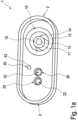
- the Figures 1a-1d show an example of a surgical device multiple socket 1 not according to the invention.
- the surgical device multiple socket 1 extends from a first end 2 to a second end 3.
- the surgical device multiple socket 1 has a flat-oval outer contour, which has two parallel, opposite flanks and on first and second end 2, 3 has a curved, in particular semi-circular geometry.
- a coaxial socket 10 is arranged in a section adjacent to the first end 2 of the surgical device multiple socket 1 .
- the coaxial socket 10 is formed by two coaxially arranged sleeves.
- the inner sleeve 11 is essentially surrounded by the outer sleeve 13 in the radial direction. Furthermore, the inner sleeve 11 has an outer diameter which has a smaller dimension than the inner diameter of the outer sleeve 13. This forms two openings through the gap between the outer and inner sleeves 13, 11 and the geometry-related cavity of the inner sleeve 11 are formed.
- the space between the outer and inner sleeves 13, 11 forms the outer annular coaxial socket opening 14 and the space formed inside the inner sleeve 11 forms the inner coaxial socket opening 12.
- the first contact opening 20 and the second contact opening 30 are arranged in a section which adjoins the second end 3 of the surgical device multiple socket 1 .
- the contact openings 20, 30 have a circular shape orthogonal to the central axis Cross-section, each of which has the same diameter as the inner coaxial socket opening 12 substantially.
- the first contact opening 20 and the second contact opening 30 lie on an imaginary connecting line that runs from the first end 2 to the second end 3 .
- the first contact opening 20 faces the second end 3 and the second contact opening 30 faces the first end 2 or the coaxial socket 10 .
- the imaginary connecting line that connects the first end 2 and the second end 3 to one another divides the surgical device multiple socket 1 into two horizontally separate halves, each of which has the same dimensions in the vertical direction.
- the center points of the first contact opening 20, the second contact opening 30 and the coaxial socket 10 lie on this line.
- the surgical device multiple socket 1 also has a positioning opening 40 .
- the positioning opening 40 has a circular cross section orthogonally to the central axis. The diameter is smaller than the diameter of the contact openings 20, 30. Furthermore, the positioning opening 40 does not lie on the connecting line connecting the centers of the contact openings 30, 40 and the inner coaxial socket 10, so that the positioning opening 40 is not aligned with the first and second contact opening 20, 30 and the coaxial socket 10 is located.
- the coaxial socket 10, the contact openings 20, 30 and the positioning opening 40 are embedded in a flat surface of the surgical device multiple socket 1 substantially.
- a connection end 22 of the first contact opening 20 and a connection end 32 of the second contact opening 30 are slightly offset into this plane, so that they are set back.
- the connection opening 42 of the positioning opening 40 and the connection end 16 of the coaxial socket 10 lie essentially in one plane with the aforementioned plane of the surgical device multiple socket 1.
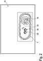
- FIG 2 shows a high-frequency generator 50 with a surgical device multiple socket 1 not according to the invention.
- the surgical device multiple socket 1 has the positioning opening 40 .
- FIG 3 12 shows an electrosurgical system 80 with a high-frequency generator 50 and a multiple socket 300 for surgical equipment, not according to the invention, to which a first electrosurgical instrument 61 is connected.
- the Electrosurgical System 80 includes the high-frequency generator 50 with a further embodiment of the surgical device multiple socket 300 and a first electrosurgical instrument 61.
- the electrosurgical instrument 61 is connected to the surgical device multiple socket 300 with a connecting cable 65 and via a plug (not shown) arranged thereon.
- the surgical device multiple socket 300 is arranged on the high-frequency generator 50 .
- a second electrosurgical instrument 62 and a third electrosurgical instrument 63 are also available.
- the electrosurgical instruments 62, 63 each have a plug 60a, 60b, the plugs 60a, 60b preferably being of a different type, for example the spacing of the contact pins is different.
- a fourth electrosurgical instrument 64 is also shown, which is connected to an electrosurgical device plug 70 via a further connecting cable 65a.
- the electrosurgical unit connector 70 is in figure 4 shown in more detail.
- the fourth electrosurgical instrument 64 can be connected to the connecting cable 65a as a fixed connection or as a plug-in connection (not shown), so that the cable 65a and the electrosurgical instrument 64 are preferably provided as separate assemblies.
- FIG 4 shows an electrosurgical device connector 70 not according to the invention.
- the electrosurgical device connector 70 comprises a contact pin 210 and a coaxial connector element 110.
- the coaxial connector element 110 has a circular sleeve, this sleeve having a thin-walled design. Within this sleeve, a contact pin is arranged coaxially, which in turn has a circular cross-section.
- FIG 5 shows a non-inventive connector with two pins 210.
- the figure 5 shows a schematic of a commercially available plug 60a for an electrosurgical instrument 62 or for connecting an electrosurgical instrument 62 to a high-frequency generator 50 via a surgical device multiple socket.
- the plug 60a has two contact pins 210 arranged on a base element.
- the contact pins 210 each have a longitudinal extent, with a circular cross section being formed orthogonally to the longitudinal extent.
- An electrosurgical instrument not according to the invention with a connector 60a according to FIG figure 5 is appropriate to the high-frequency generator 50 out figure 2 to be connected.
- On the one hand there is the possibility to use a connector, one of which pin 210 in the inner coaxial socket opening 12 and the other contact pin 210 is inserted into the first contact opening 20.
- the aforesaid insertion of the contact pins 210 into the openings preferably occurs simultaneously, since the contact pins 210 are arranged fixedly and lying in one plane on a main body of the connector 60a. Because the surgical device multiple socket 1, 300 includes the first and second contact opening, it is possible to use plugs whose spacing between the contact pins 210 is different. It is also possible to use a plug that is suitable for a coaxial socket, for example a coaxial plug element 110.
- a special electrosurgical unit plug 70 which includes a coaxial plug element 110 and at least one contact pin 210 . It is also possible to use a connector that includes a coaxial connector element 110 and two contact pins 210, in which case the spacing of the two contact pins 210 has the same dimensions as the spacing of the two contact openings 20, 30. In addition, there is the Possibility of using a plug that includes one of the aforementioned embodiments, but also includes a positioning pin, with this positioning pin being inserted into the positioning opening 40 of the surgical device multiple socket 1, 300.
- the large number of compatible plugs results in the fact that only one surgical device multiple socket has to be integrated into the high-frequency generator 50 and not, as before, a socket designed specifically for this plug for each plug. This in turn results in less space being required for the surgical device multiple socket, so that a more compact design of the high-frequency generator can be implemented.
- electrosurgical instruments from different manufacturers and with different plugs can be used on a single high-frequency generator, so that only a single high-frequency generator must be used in a cost-effective manner, which can operate a large number of different electrosurgical instruments without having to use adapters for this purpose .
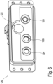
- FIG 6 shows a surgical device multiple socket for a Bovie plug known in the prior art.
- the surgical device multiple socket 120 has a first contact opening 124 , a second contact opening 126 and a third contact opening 128 .
- the second contact opening 126 is located adjacent to the first contact opening 124 and the third contact opening 128 is located adjacent to the second contact opening 126 , where the first contact opening 124 is not located adjacent to the third contact opening 128 .
- the contact holes 124, 126, 128 are arranged on a straight line such that the centers of the contact holes 124, 126, 128 are placed on the straight line.
- An arrangement of several plugs is not possible or only possible to a limited extent in the case of the surgical device multiple socket 120 .
- the surgical device multiple socket 120 is not designed for the connection of coaxial plugs.
- the surgical device multiple socket 120 has a large contact opening 122 which has a diameter in the direction orthogonal to the insertion direction which is twice the diameter of the contact opening 124, 126, 128. Furthermore, the large contact opening 122 is in relation to one direction of the aforesaid straight line between the second contact hole 126 and the third contact hole 128 . It can also be seen that the center point of the large contact opening 122 is spaced from the straight line. When the surgical device multiple socket 120 is installed, the center point of the large contact opening 122 is arranged above the center points of the contact openings 124 , 126 , 128 . In particular, the large contact opening 122 is designed for connecting Bovie connectors.
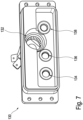
- the surgical device multiple socket 130 shown in the prior art which is known in the prior art, has essentially the same structure or arrangement as the surgical device multiple socket 120 in FIG figure 6 .
- the surgical device multiple socket 130 has a first contact opening 134, a second contact opening 136 and a third contact opening 138, which are arranged analogously to the contact openings 124, 126, 128 of the surgical device multiple socket 120.
- the surgical device multiple socket 130 shown here has a coaxial socket 132.
- the center point of the coaxial socket 132 is located essentially the same as the center point of the large contact opening 122 on the surgical device multiple socket 120.
- an arrangement of several plugs is not possible or only possible to a limited extent.
- the surgical device multiple socket 130 is not designed for the connection of Bovie plugs.
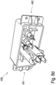
- the Figures 8a-8d show an embodiment of a surgical device multiple socket according to the invention.
- the surgical device multiple socket 400 extends in the direction of a width B from a first end 402 to a second end 404 .
- the first contact opening 414 is the one of said contact openings 414, 416, 418 that faces the first end.
- the third contact opening 418 is the contact opening that faces the second end 404 .
- the second contact hole 416 is located between the first contact hole 414 and the third contact hole 418 in the width direction.
- the contact openings 414, 416, 418 each have an equal diameter orthogonal to an insertion direction and also each have a center point.
- the centers of the contact openings 414, 416, 418 lie on a horizontal line 408 which is aligned in the width B direction. With regard to the width B, it can be seen that the distance between the first contact opening 414 and the second contact opening 416 is significantly smaller than the distance between the second contact opening 416 and the third contact opening 418.
- the surgical device multiple socket 400 also has a coaxial socket 420 and a fourth contact opening 422 .
- the fourth contact opening 422 has a diameter orthogonal to an insertion direction, which has twice the dimension of the respective diameters of the contact openings 414, 416, 418.
- the coaxial socket 420 and the fourth contact opening 422 each have a midpoint, the midpoints of the coaxial socket 420 and the fourth contact opening 422 being arranged on a straight vertical line 410, this vertical line being arranged parallel to a height of the surgical device multiple socket. It can also be seen that the midpoints of the coaxial jack 420 and the fourth contact opening 422 are located between the second contact opening 416 and the third contact opening 418 with respect to the width B.
- the distance between the centers of the coaxial socket 420 and the fourth contact opening 422 and the center of the second contact opening 416 and the center of the third contact opening 418 is the same.
- the midpoint of coaxial jack 420 is below horizontal line 408 with respect to elevation.
- the midpoint of fourth contact opening 422 is above horizontal line 408 with respect to elevation.
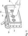
- FIGs 9 to 11 show the use of the surgical device multiple socket 400 according to the invention, a state with different plugs 220, 230, 240 being shown in each case.
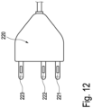
- First contact opening 414, second contact opening 416 and third contact opening 418 are used to receive a three-pin connector 220 having a first contact pin 221, a second contact pin 222 and a third contact pin 223.
- the three-pin connector 220 with the first pin 221, the second pin 222 and the third pin 223 is in a different perspective figure 12 shown.
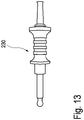
- figure 10 12 shows how a connector with a large contact pin, which is also known in the prior art as a Bovie connector, is arranged on the surgical device multiple socket 400 .
- the plug with the large contact pin 230 is also in again from a different perspective figure 13 shown.
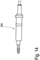
- figure 11 shows the use of a coaxial connector on the surgical device multiple socket 400 by the coaxial connector 240 being arranged in the coaxial socket 420.
- Such a coaxial connector is an example in figure 13 shown from a different perspective.
- the surgical device multiple socket 400 has a number of advantages over the surgical device multiple sockets known in the prior art.
- the plug-in options of the sockets currently used on surgical devices are integrated into a single new socket in a previously unknown arrangement, so that the surgical device multiple socket 400 can provide a more practicable, safer and more cost-effective high-frequency generator overall.
- the sockets can be arranged in such a way that two or more plugs can be arranged on the socket at the same time. Two or more plugs can thus be connected to the surgical device multiple socket 400 . It follows that for a high-frequency generator only one socket or, if necessary, two sockets must be arranged, so that the number of sockets is reduced.
Landscapes
- Health & Medical Sciences (AREA)
- Surgery (AREA)
- Engineering & Computer Science (AREA)
- Life Sciences & Earth Sciences (AREA)
- Biomedical Technology (AREA)
- Molecular Biology (AREA)
- Nuclear Medicine, Radiotherapy & Molecular Imaging (AREA)
- Plasma & Fusion (AREA)
- Physics & Mathematics (AREA)
- Heart & Thoracic Surgery (AREA)
- Medical Informatics (AREA)
- Otolaryngology (AREA)
- Animal Behavior & Ethology (AREA)
- General Health & Medical Sciences (AREA)
- Public Health (AREA)
- Veterinary Medicine (AREA)
- Surgical Instruments (AREA)
- Coupling Device And Connection With Printed Circuit (AREA)
Claims (5)
- Prise multiple d'appareil chirurgical (400) pour un générateur haute fréquence (50) pour le raccordement d'un instrument électrochirurgical (61, 62, 63), à savoir d'un applicateur monopolaire, comprenant- une prise coaxiale (420), qui est réalisée pour recevoir un élément fiche coaxiale (110, 240), et- une première ouverture de contact (414), qui est réalisée pour recevoir une première broche de contact (210, 221, 222, 223) d'une fiche à trois broches (220), et une deuxième ouverture de contact (416), qui est réalisée pour recevoir une deuxième broche de contact de la fiche à trois broches, et- une troisième ouverture de contact (418), qui est réalisée pour recevoir une troisième broche de contact de la fiche à trois broches, dans laquelle les centres de la première ouverture de contact et de la deuxième ouverture de contact et de la troisième ouverture de contact sont disposés sur une ligne droite, et- une quatrième ouverture de contact (422) pour la réception d'une fiche Bovie (230),- dans laquelle la prise coaxiale (420) et la quatrième ouverture de contact (422) sont disposées entre la deuxième ouverture de contact (416) et la troisième ouverture de contact (418), et- la prise coaxiale et la quatrième ouverture de contact sont disposées de telle sorte qu'une ligne reliant les centres de celles-ci est orientée perpendiculairement à une ligne de liaison, reliant les centres de la première ouverture de contact (414) et de la deuxième ouverture de contact (416) et de la troisième ouverture de contact (418).
- Prise multiple d'appareil chirurgical (400) selon la revendication précédente, dans laquelle la quatrième ouverture de contact (422) et une, deux ou plusieurs autres ouvertures de contact présentent respectivement un diamètre orienté dans la direction perpendiculaire par rapport à une direction d'enfichage,- dans laquelle les une, deux ou plusieurs autres ouvertures de contact sont sélectionnées dans le groupe constitué deo la première ouverture de contact (414), eto la deuxième ouverture de contact (416), eto la troisième ouverture de contact (418),- dans laquelle le diamètre de la quatrième ouverture de contact est supérieur au diamètre ou aux diamètres des une, deux ou plusieurs autres ouvertures de contact, dans laquelle le diamètre de la quatrième ouverture de contact est réalisé de préférence entre 6 mm et 10 mm, en particulier entre 7,5 mm et 8,5 mm.
- Prise multiple d'appareil chirurgical (400) selon au moins l'une des revendications précédentes, dans laquelle- la première ouverture de contact est disposée sur le côté de la deuxième ouverture de contact qui est opposé à la troisième ouverture de contact, et/ou- la prise coaxiale et la quatrième ouverture de contact sont espacées l'une de l'autre de telle sorte qu'une fiche coaxiale peut être disposée dans la prise coaxiale et simultanément une broche de contact, en particulier une fiche Bovie, peut être disposée dans la quatrième ouverture de contact.
- Générateur haute fréquence électrochirurgical (50), comprenant :- une prise multiple d'appareil chirurgical (1, 300) selon au moins l'une des revendications précédentes.
- Système électrochirurgical, comprenant :- un générateur haute fréquence (50) selon la revendication précédente, et- un instrument électrochirurgical raccordé ou pouvant être raccordé par l'intermédiaire de la prise multiple d'appareil chirurgical (1, 300, 400) du générateur haute fréquence.
Priority Applications (1)
| Application Number | Priority Date | Filing Date | Title |
|---|---|---|---|
| EP22189291.2A EP4119081A1 (fr) | 2016-02-15 | 2017-02-15 | Prise multiple pour appareils chirurgicaux, générateur haute fréquence d'électrochirurgie, connecteur d'appareil d'électrochirurgie et système d'électrochirurgie |
Applications Claiming Priority (2)
| Application Number | Priority Date | Filing Date | Title |
|---|---|---|---|
| DE102016102640.9A DE102016102640A1 (de) | 2016-02-15 | 2016-02-15 | Chirurgiegeräte-Mehrfachbuchse, Elektrochirurgie-Hochfrequenzgenerator, Elektrochirurgiegerätestecker und Elektrochirurgisches System |
| PCT/EP2017/053400 WO2017140727A1 (fr) | 2016-02-15 | 2017-02-15 | Prise multiple pour appareil chirurgical, générateur haute fréquence électrochirurgical, fiche pour appareil électrochirurgical et système électrochirurgical |
Related Child Applications (2)
| Application Number | Title | Priority Date | Filing Date |
|---|---|---|---|
| EP22189291.2A Division EP4119081A1 (fr) | 2016-02-15 | 2017-02-15 | Prise multiple pour appareils chirurgicaux, générateur haute fréquence d'électrochirurgie, connecteur d'appareil d'électrochirurgie et système d'électrochirurgie |
| EP22189291.2A Division-Into EP4119081A1 (fr) | 2016-02-15 | 2017-02-15 | Prise multiple pour appareils chirurgicaux, générateur haute fréquence d'électrochirurgie, connecteur d'appareil d'électrochirurgie et système d'électrochirurgie |
Publications (2)
| Publication Number | Publication Date |
|---|---|
| EP3416577A1 EP3416577A1 (fr) | 2018-12-26 |
| EP3416577B1 true EP3416577B1 (fr) | 2023-04-05 |
Family
ID=58213055
Family Applications (2)
| Application Number | Title | Priority Date | Filing Date |
|---|---|---|---|
| EP22189291.2A Pending EP4119081A1 (fr) | 2016-02-15 | 2017-02-15 | Prise multiple pour appareils chirurgicaux, générateur haute fréquence d'électrochirurgie, connecteur d'appareil d'électrochirurgie et système d'électrochirurgie |
| EP17708444.9A Active EP3416577B1 (fr) | 2016-02-15 | 2017-02-15 | Prise multiple pour appareil chirurgical, générateur haute fréquence électrochirurgical et système électrochirurgical |
Family Applications Before (1)
| Application Number | Title | Priority Date | Filing Date |
|---|---|---|---|
| EP22189291.2A Pending EP4119081A1 (fr) | 2016-02-15 | 2017-02-15 | Prise multiple pour appareils chirurgicaux, générateur haute fréquence d'électrochirurgie, connecteur d'appareil d'électrochirurgie et système d'électrochirurgie |
Country Status (7)
| Country | Link |
|---|---|
| US (1) | US11298176B2 (fr) |
| EP (2) | EP4119081A1 (fr) |
| JP (1) | JP6835862B2 (fr) |
| CN (2) | CN108697455A (fr) |
| DE (1) | DE102016102640A1 (fr) |
| ES (1) | ES2945696T3 (fr) |
| WO (1) | WO2017140727A1 (fr) |
Families Citing this family (2)
| Publication number | Priority date | Publication date | Assignee | Title |
|---|---|---|---|---|
| EP3133700B1 (fr) * | 2015-08-20 | 2019-10-16 | Kistler Holding AG | Interface de cablage pour une machine de production de l'industrie de traitement du plastique et procédé de reequipement d'une telle machine de production |
| US11527876B2 (en) * | 2019-12-02 | 2022-12-13 | Claudio A. Fernandez | Pluggable electrical outlet system |
Citations (1)
| Publication number | Priority date | Publication date | Assignee | Title |
|---|---|---|---|---|
| US20040097117A1 (en) * | 2002-11-18 | 2004-05-20 | Gonnering Wayne J. | Monopolar electrosurgical multi-plug connector device and method which accepts multiple different connector plugs |
Family Cites Families (43)
| Publication number | Priority date | Publication date | Assignee | Title |
|---|---|---|---|---|
| US3673541A (en) * | 1970-08-06 | 1972-06-27 | Amp Inc | Composite electrical and fluid or air connector |
| DE2136022C3 (de) * | 1971-07-19 | 1979-06-13 | Siemens Ag | Mehrfachsteckvorrichtung |
| US5211581A (en) * | 1992-07-30 | 1993-05-18 | Motorola, Inc. | Electrical connector assembly and method therefor |
| FR2712737B1 (fr) * | 1993-11-19 | 1996-01-12 | Sextant Avionique | Connecteur mixte à broches électrofluidiques. |
| US5817092A (en) | 1995-11-09 | 1998-10-06 | Radio Therapeutics Corporation | Apparatus, system and method for delivering radio frequency energy to a treatment site |
| AU2005200527B2 (en) * | 1998-10-23 | 2007-01-25 | Covidien Ag | Electrosurgical device having a dielectric seal |
| US6144561A (en) * | 1998-12-01 | 2000-11-07 | Scientific-Atlanta, Inc. | Connectorization panel assembly for circuit board housing rack |
| SE9902778L (sv) * | 1999-07-23 | 2001-01-24 | Uma Trading Ab | Koppling föranslutning av ett batteri till ett laddningsaggregat |
| US8048070B2 (en) * | 2000-03-06 | 2011-11-01 | Salient Surgical Technologies, Inc. | Fluid-assisted medical devices, systems and methods |
| EP1379187A2 (fr) | 2001-04-18 | 2004-01-14 | Smith & Nephew, Inc. | Systemes electrochirurgicaux |
| ES2381407T3 (es) * | 2001-04-20 | 2012-05-28 | Tyco Healthcare Group Lp | Dispositivo quirúrgico bipolar o ultrasónico |
| CN2548279Y (zh) * | 2002-05-30 | 2003-04-30 | 林锡忠 | 光电合一的电缆、插头及插座 |
| US20040097912A1 (en) * | 2002-11-18 | 2004-05-20 | Gonnering Wayne J. | Electrosurgical generator and method with removable front panel having replaceable electrical connection sockets and illuminated receptacles |
| DE10258689B3 (de) * | 2002-12-13 | 2004-07-08 | Wolfgang B. THÖRNER | Koaxiale Steckverbindung |
| US6746284B1 (en) * | 2003-10-02 | 2004-06-08 | Hon Hai Precision Ind. Co., Ltd. | Electrical connector assembly having signal and power terminals |
| JP4429272B2 (ja) | 2003-11-20 | 2010-03-10 | コヴィディエン アクチェンゲゼルシャフト | 電気外科用発電機のためのコネクタシステム |
| GB2415097A (en) * | 2004-06-12 | 2005-12-14 | Quentin Cobham | Electrical socket capable of receiving polarised or non-polarised plug |
| JP2006012573A (ja) * | 2004-06-25 | 2006-01-12 | Jst Mfg Co Ltd | 電気的接続装置 |
| US7465177B2 (en) * | 2006-10-10 | 2008-12-16 | Tyco Electronics Corporation | Electrical connector having a fluid coupling |
| CN200972903Y (zh) * | 2006-11-21 | 2007-11-07 | 镇江通达电子有限公司 | 多芯同轴及信号电缆插座 |
| CN101217223A (zh) * | 2007-01-04 | 2008-07-09 | 南京依纳科技有限公司 | 小型射频同轴连接器 |
| WO2009071256A1 (fr) * | 2007-12-03 | 2009-06-11 | Erbe Elektromedizin Gmbh | Prise femelle pour appareil chirurgical hf |
| DE102007061483A1 (de) | 2007-12-20 | 2009-07-02 | Erbe Elektromedizin Gmbh | Chirurgiegerätesteckersystem |
| US7704077B1 (en) * | 2009-04-13 | 2010-04-27 | Tyco Electronics Corporation | Low loss board to board connection system |
| US7985083B2 (en) * | 2009-05-18 | 2011-07-26 | Phihong Usa Corporation | Interface between connectable electrical devices |
| JP2010057944A (ja) * | 2009-11-04 | 2010-03-18 | Covidien Ag | 電気外科用発電機のためのコネクタシステム |
| US8685018B2 (en) * | 2010-10-15 | 2014-04-01 | Arthrocare Corporation | Electrosurgical wand and related method and system |
| PL2486885T3 (pl) * | 2011-02-09 | 2013-09-30 | Erbe Elektromedizin | Gniazdo wtykowe |
| US8282415B1 (en) * | 2011-04-21 | 2012-10-09 | Tyco Electronics Corporation | Multi-port connector assembly |
| US9358065B2 (en) * | 2011-06-23 | 2016-06-07 | Covidien Lp | Shaped electrode bipolar resection apparatus, system and methods of use |
| JP5849185B2 (ja) * | 2011-10-14 | 2016-01-27 | パナソニックIpマネジメント株式会社 | アンテナソケット |
| EP2656805B1 (fr) | 2012-04-26 | 2017-03-15 | Erbe Elektromedizin GmbH | Agencement de douille pour un appareil électromédical |
| GB2504076A (en) * | 2012-07-16 | 2014-01-22 | Nicoventures Holdings Ltd | Electronic smoking device |
| CN204409583U (zh) * | 2012-09-28 | 2015-06-24 | 惠州市吉瑞科技有限公司 | 电子烟及其电子烟装置 |
| CN202817435U (zh) * | 2012-10-17 | 2013-03-20 | 松尼电工有限公司 | 小五孔插座 |
| WO2015042796A1 (fr) * | 2013-09-25 | 2015-04-02 | 吉瑞高新科技股份有限公司 | Ensemble d'atomisation et cigarette electronique |
| US9496668B1 (en) * | 2014-09-30 | 2016-11-15 | Apple Inc. | Connection structures for electrical components in an electronic device |
| CN104882727B (zh) * | 2015-04-30 | 2018-01-02 | 成都锐奕信息技术有限公司 | 稳定可靠的电气连接机构 |
| GB201511349D0 (en) * | 2015-06-29 | 2015-08-12 | Nicoventures Holdings Ltd | Electronic aerosol provision systems |
| US9595790B1 (en) * | 2016-03-08 | 2017-03-14 | Faraday&Future Inc. | Electric vehicle charge port |
| US9882317B1 (en) * | 2016-09-15 | 2018-01-30 | Te Connectivity Corporation | Connector system with hybrid electrical connectors |
| US10932705B2 (en) * | 2017-05-08 | 2021-03-02 | Masimo Corporation | System for displaying and controlling medical monitoring data |
| CN207651722U (zh) * | 2017-11-17 | 2018-07-24 | 连展科技电子(昆山)有限公司 | 电连接器组件 |
-
2016
- 2016-02-15 DE DE102016102640.9A patent/DE102016102640A1/de not_active Ceased
-
2017
- 2017-02-15 JP JP2018543134A patent/JP6835862B2/ja active Active
- 2017-02-15 CN CN201780011347.8A patent/CN108697455A/zh active Pending
- 2017-02-15 US US16/066,885 patent/US11298176B2/en active Active
- 2017-02-15 EP EP22189291.2A patent/EP4119081A1/fr active Pending
- 2017-02-15 EP EP17708444.9A patent/EP3416577B1/fr active Active
- 2017-02-15 CN CN202211097154.8A patent/CN115411583A/zh active Pending
- 2017-02-15 WO PCT/EP2017/053400 patent/WO2017140727A1/fr not_active Ceased
- 2017-02-15 ES ES17708444T patent/ES2945696T3/es active Active
Patent Citations (1)
| Publication number | Priority date | Publication date | Assignee | Title |
|---|---|---|---|---|
| US20040097117A1 (en) * | 2002-11-18 | 2004-05-20 | Gonnering Wayne J. | Monopolar electrosurgical multi-plug connector device and method which accepts multiple different connector plugs |
Also Published As
| Publication number | Publication date |
|---|---|
| JP6835862B2 (ja) | 2021-02-24 |
| EP4119081A1 (fr) | 2023-01-18 |
| EP3416577A1 (fr) | 2018-12-26 |
| ES2945696T3 (es) | 2023-07-05 |
| DE102016102640A1 (de) | 2017-08-17 |
| JP2019506239A (ja) | 2019-03-07 |
| US11298176B2 (en) | 2022-04-12 |
| CN115411583A (zh) | 2022-11-29 |
| CN108697455A (zh) | 2018-10-23 |
| US20190008575A1 (en) | 2019-01-10 |
| WO2017140727A1 (fr) | 2017-08-24 |
Similar Documents
| Publication | Publication Date | Title |
|---|---|---|
| EP2486885B1 (fr) | Fiche femelle universelle | |
| EP3031103B1 (fr) | Système comprenant une pluralité de modules de connecteur électrique et un cadre de support électriquement conducteur | |
| DE2324658B2 (de) | Sonde zum koagulieren von koerpergewebe | |
| DE102010029459A1 (de) | Elektrochirurgische Vorrichtung | |
| EP3477784B1 (fr) | Dispositif de traitement pour un instrument médical microinvasif | |
| DE102007061483A1 (de) | Chirurgiegerätesteckersystem | |
| DE69622400T2 (de) | Elektrischer verbinder zum anschluss für eine medizinische vorrichtung | |
| DE102020100121A1 (de) | Implantierbare Elektrode mit einer Stichleitung | |
| EP2228027B1 (fr) | Appareil chirurgical haute fréquence | |
| EP2653123B1 (fr) | Outil pour un instrument médical | |
| EP4119081A1 (fr) | Prise multiple pour appareils chirurgicaux, générateur haute fréquence d'électrochirurgie, connecteur d'appareil d'électrochirurgie et système d'électrochirurgie | |
| EP2653119B1 (fr) | Instrument médical et procédé d'assemblage d'un instrument médical | |
| DE102022118628A1 (de) | Anschlussanordnung, Verfahren zur Herstellung einer Anschlussanordnung und chirurgisches Instrument | |
| EP1714672A1 (fr) | Adaptateur de relation de contact visant la création d'un contact électrique occasionnel entre deux connecteurs | |
| DE102006037122B3 (de) | Medizinische Elektrode mit wenigstens zwei Polen und einem Stecker und deren Verwendung | |
| EP2376177B1 (fr) | Raccord de flexible pour appareil chirurgical haute fréquence, poignée pour appareil chirurgical haute fréquence, et procédé de raccordement de flexibles pour appareil chirurgical haute fréquence au moyen d'un tel raccord de flexible | |
| DE102016211076B4 (de) | Medizintechnische Mehrfachbuchse, medizintechnisches Gerät und medizintechnisches System | |
| EP3448293B1 (fr) | Accouplement d'un instrument chirurgical hf endoscopique et instrument chirurgical hf muni d'un tel accouplement | |
| EP2007302A1 (fr) | Electrode plane | |
| EP4489676B1 (fr) | Instrument électrochirurgical, et agencement d'électrode et dispositif de base pour celui-ci | |
| EP1771120B1 (fr) | Dispositif adaptateur | |
| DE4430595C2 (de) | Elektrodenstecker | |
| DE202022104899U1 (de) | Adaptive Einsatzbaugruppe und Steckbüchse für einen chirurgischen Instrumentgenerator | |
| WO2018001559A1 (fr) | Dispositif d'accouplement | |
| DE202023106679U1 (de) | Leiter eines Physiotherapiegeräts und Physiotherapiegerät |
Legal Events
| Date | Code | Title | Description |
|---|---|---|---|
| STAA | Information on the status of an ep patent application or granted ep patent |
Free format text: STATUS: UNKNOWN |
|
| STAA | Information on the status of an ep patent application or granted ep patent |
Free format text: STATUS: THE INTERNATIONAL PUBLICATION HAS BEEN MADE |
|
| PUAI | Public reference made under article 153(3) epc to a published international application that has entered the european phase |
Free format text: ORIGINAL CODE: 0009012 |
|
| STAA | Information on the status of an ep patent application or granted ep patent |
Free format text: STATUS: REQUEST FOR EXAMINATION WAS MADE |
|
| 17P | Request for examination filed |
Effective date: 20180917 |
|
| AK | Designated contracting states |
Kind code of ref document: A1 Designated state(s): AL AT BE BG CH CY CZ DE DK EE ES FI FR GB GR HR HU IE IS IT LI LT LU LV MC MK MT NL NO PL PT RO RS SE SI SK SM TR |
|
| AX | Request for extension of the european patent |
Extension state: BA ME |
|
| RIN1 | Information on inventor provided before grant (corrected) |
Inventor name: ARNOLD, MARIO Inventor name: HOLUB, BENJAMIN |
|
| DAV | Request for validation of the european patent (deleted) | ||
| DAX | Request for extension of the european patent (deleted) | ||
| STAA | Information on the status of an ep patent application or granted ep patent |
Free format text: STATUS: EXAMINATION IS IN PROGRESS |
|
| 17Q | First examination report despatched |
Effective date: 20210412 |
|
| GRAP | Despatch of communication of intention to grant a patent |
Free format text: ORIGINAL CODE: EPIDOSNIGR1 |
|
| STAA | Information on the status of an ep patent application or granted ep patent |
Free format text: STATUS: GRANT OF PATENT IS INTENDED |
|
| RIC1 | Information provided on ipc code assigned before grant |
Ipc: H01R 24/76 20110101ALN20220207BHEP Ipc: H01R 24/40 20110101ALN20220207BHEP Ipc: A61B 18/00 20060101ALN20220207BHEP Ipc: A61B 18/12 20060101AFI20220207BHEP |
|
| INTG | Intention to grant announced |
Effective date: 20220316 |
|
| GRAJ | Information related to disapproval of communication of intention to grant by the applicant or resumption of examination proceedings by the epo deleted |
Free format text: ORIGINAL CODE: EPIDOSDIGR1 |
|
| STAA | Information on the status of an ep patent application or granted ep patent |
Free format text: STATUS: EXAMINATION IS IN PROGRESS |
|
| INTC | Intention to grant announced (deleted) | ||
| RIC1 | Information provided on ipc code assigned before grant |
Ipc: H01R 24/76 20110101ALN20220816BHEP Ipc: H01R 24/40 20110101ALN20220816BHEP Ipc: A61B 18/00 20060101ALN20220816BHEP Ipc: A61B 18/12 20060101AFI20220816BHEP |
|
| GRAP | Despatch of communication of intention to grant a patent |
Free format text: ORIGINAL CODE: EPIDOSNIGR1 |
|
| STAA | Information on the status of an ep patent application or granted ep patent |
Free format text: STATUS: GRANT OF PATENT IS INTENDED |
|
| INTG | Intention to grant announced |
Effective date: 20220929 |
|
| GRAS | Grant fee paid |
Free format text: ORIGINAL CODE: EPIDOSNIGR3 |
|
| GRAA | (expected) grant |
Free format text: ORIGINAL CODE: 0009210 |
|
| STAA | Information on the status of an ep patent application or granted ep patent |
Free format text: STATUS: THE PATENT HAS BEEN GRANTED |
|
| AK | Designated contracting states |
Kind code of ref document: B1 Designated state(s): AL AT BE BG CH CY CZ DE DK EE ES FI FR GB GR HR HU IE IS IT LI LT LU LV MC MK MT NL NO PL PT RO RS SE SI SK SM TR |
|
| REG | Reference to a national code |
Ref country code: GB Ref legal event code: FG4D Free format text: NOT ENGLISH |
|
| REG | Reference to a national code |
Ref country code: DE Ref legal event code: R096 Ref document number: 502017014594 Country of ref document: DE |
|
| REG | Reference to a national code |
Ref country code: CH Ref legal event code: EP |
|
| REG | Reference to a national code |
Ref country code: AT Ref legal event code: REF Ref document number: 1557684 Country of ref document: AT Kind code of ref document: T Effective date: 20230415 |
|
| REG | Reference to a national code |
Ref country code: IE Ref legal event code: FG4D Free format text: LANGUAGE OF EP DOCUMENT: GERMAN |
|
| P01 | Opt-out of the competence of the unified patent court (upc) registered |
Effective date: 20230519 |
|
| REG | Reference to a national code |
Ref country code: ES Ref legal event code: FG2A Ref document number: 2945696 Country of ref document: ES Kind code of ref document: T3 Effective date: 20230705 |
|
| REG | Reference to a national code |
Ref country code: LT Ref legal event code: MG9D |
|
| REG | Reference to a national code |
Ref country code: NL Ref legal event code: MP Effective date: 20230405 |
|
| PG25 | Lapsed in a contracting state [announced via postgrant information from national office to epo] |
Ref country code: NL Free format text: LAPSE BECAUSE OF FAILURE TO SUBMIT A TRANSLATION OF THE DESCRIPTION OR TO PAY THE FEE WITHIN THE PRESCRIBED TIME-LIMIT Effective date: 20230405 |
|
| PG25 | Lapsed in a contracting state [announced via postgrant information from national office to epo] |
Ref country code: SE Free format text: LAPSE BECAUSE OF FAILURE TO SUBMIT A TRANSLATION OF THE DESCRIPTION OR TO PAY THE FEE WITHIN THE PRESCRIBED TIME-LIMIT Effective date: 20230405 Ref country code: PT Free format text: LAPSE BECAUSE OF FAILURE TO SUBMIT A TRANSLATION OF THE DESCRIPTION OR TO PAY THE FEE WITHIN THE PRESCRIBED TIME-LIMIT Effective date: 20230807 Ref country code: NO Free format text: LAPSE BECAUSE OF FAILURE TO SUBMIT A TRANSLATION OF THE DESCRIPTION OR TO PAY THE FEE WITHIN THE PRESCRIBED TIME-LIMIT Effective date: 20230705 |
|
| PG25 | Lapsed in a contracting state [announced via postgrant information from national office to epo] |
Ref country code: RS Free format text: LAPSE BECAUSE OF FAILURE TO SUBMIT A TRANSLATION OF THE DESCRIPTION OR TO PAY THE FEE WITHIN THE PRESCRIBED TIME-LIMIT Effective date: 20230405 Ref country code: PL Free format text: LAPSE BECAUSE OF FAILURE TO SUBMIT A TRANSLATION OF THE DESCRIPTION OR TO PAY THE FEE WITHIN THE PRESCRIBED TIME-LIMIT Effective date: 20230405 Ref country code: LV Free format text: LAPSE BECAUSE OF FAILURE TO SUBMIT A TRANSLATION OF THE DESCRIPTION OR TO PAY THE FEE WITHIN THE PRESCRIBED TIME-LIMIT Effective date: 20230405 Ref country code: LT Free format text: LAPSE BECAUSE OF FAILURE TO SUBMIT A TRANSLATION OF THE DESCRIPTION OR TO PAY THE FEE WITHIN THE PRESCRIBED TIME-LIMIT Effective date: 20230405 Ref country code: IS Free format text: LAPSE BECAUSE OF FAILURE TO SUBMIT A TRANSLATION OF THE DESCRIPTION OR TO PAY THE FEE WITHIN THE PRESCRIBED TIME-LIMIT Effective date: 20230805 Ref country code: HR Free format text: LAPSE BECAUSE OF FAILURE TO SUBMIT A TRANSLATION OF THE DESCRIPTION OR TO PAY THE FEE WITHIN THE PRESCRIBED TIME-LIMIT Effective date: 20230405 Ref country code: GR Free format text: LAPSE BECAUSE OF FAILURE TO SUBMIT A TRANSLATION OF THE DESCRIPTION OR TO PAY THE FEE WITHIN THE PRESCRIBED TIME-LIMIT Effective date: 20230706 Ref country code: AL Free format text: LAPSE BECAUSE OF FAILURE TO SUBMIT A TRANSLATION OF THE DESCRIPTION OR TO PAY THE FEE WITHIN THE PRESCRIBED TIME-LIMIT Effective date: 20230405 |
|
| PG25 | Lapsed in a contracting state [announced via postgrant information from national office to epo] |
Ref country code: FI Free format text: LAPSE BECAUSE OF FAILURE TO SUBMIT A TRANSLATION OF THE DESCRIPTION OR TO PAY THE FEE WITHIN THE PRESCRIBED TIME-LIMIT Effective date: 20230405 |
|
| REG | Reference to a national code |
Ref country code: DE Ref legal event code: R097 Ref document number: 502017014594 Country of ref document: DE |
|
| PG25 | Lapsed in a contracting state [announced via postgrant information from national office to epo] |
Ref country code: SK Free format text: LAPSE BECAUSE OF FAILURE TO SUBMIT A TRANSLATION OF THE DESCRIPTION OR TO PAY THE FEE WITHIN THE PRESCRIBED TIME-LIMIT Effective date: 20230405 |
|
| PG25 | Lapsed in a contracting state [announced via postgrant information from national office to epo] |
Ref country code: SM Free format text: LAPSE BECAUSE OF FAILURE TO SUBMIT A TRANSLATION OF THE DESCRIPTION OR TO PAY THE FEE WITHIN THE PRESCRIBED TIME-LIMIT Effective date: 20230405 Ref country code: SK Free format text: LAPSE BECAUSE OF FAILURE TO SUBMIT A TRANSLATION OF THE DESCRIPTION OR TO PAY THE FEE WITHIN THE PRESCRIBED TIME-LIMIT Effective date: 20230405 Ref country code: RO Free format text: LAPSE BECAUSE OF FAILURE TO SUBMIT A TRANSLATION OF THE DESCRIPTION OR TO PAY THE FEE WITHIN THE PRESCRIBED TIME-LIMIT Effective date: 20230405 Ref country code: EE Free format text: LAPSE BECAUSE OF FAILURE TO SUBMIT A TRANSLATION OF THE DESCRIPTION OR TO PAY THE FEE WITHIN THE PRESCRIBED TIME-LIMIT Effective date: 20230405 Ref country code: DK Free format text: LAPSE BECAUSE OF FAILURE TO SUBMIT A TRANSLATION OF THE DESCRIPTION OR TO PAY THE FEE WITHIN THE PRESCRIBED TIME-LIMIT Effective date: 20230405 Ref country code: CZ Free format text: LAPSE BECAUSE OF FAILURE TO SUBMIT A TRANSLATION OF THE DESCRIPTION OR TO PAY THE FEE WITHIN THE PRESCRIBED TIME-LIMIT Effective date: 20230405 |
|
| PLBE | No opposition filed within time limit |
Free format text: ORIGINAL CODE: 0009261 |
|
| STAA | Information on the status of an ep patent application or granted ep patent |
Free format text: STATUS: NO OPPOSITION FILED WITHIN TIME LIMIT |
|
| 26N | No opposition filed |
Effective date: 20240108 |
|
| PG25 | Lapsed in a contracting state [announced via postgrant information from national office to epo] |
Ref country code: SI Free format text: LAPSE BECAUSE OF FAILURE TO SUBMIT A TRANSLATION OF THE DESCRIPTION OR TO PAY THE FEE WITHIN THE PRESCRIBED TIME-LIMIT Effective date: 20230405 |
|
| PG25 | Lapsed in a contracting state [announced via postgrant information from national office to epo] |
Ref country code: SI Free format text: LAPSE BECAUSE OF FAILURE TO SUBMIT A TRANSLATION OF THE DESCRIPTION OR TO PAY THE FEE WITHIN THE PRESCRIBED TIME-LIMIT Effective date: 20230405 |
|
| PG25 | Lapsed in a contracting state [announced via postgrant information from national office to epo] |
Ref country code: MC Free format text: LAPSE BECAUSE OF FAILURE TO SUBMIT A TRANSLATION OF THE DESCRIPTION OR TO PAY THE FEE WITHIN THE PRESCRIBED TIME-LIMIT Effective date: 20230405 |
|
| REG | Reference to a national code |
Ref country code: CH Ref legal event code: PL |
|
| PG25 | Lapsed in a contracting state [announced via postgrant information from national office to epo] |
Ref country code: LU Free format text: LAPSE BECAUSE OF NON-PAYMENT OF DUE FEES Effective date: 20240215 |
|
| PG25 | Lapsed in a contracting state [announced via postgrant information from national office to epo] |
Ref country code: CH Free format text: LAPSE BECAUSE OF NON-PAYMENT OF DUE FEES Effective date: 20240229 |
|
| PG25 | Lapsed in a contracting state [announced via postgrant information from national office to epo] |
Ref country code: LU Free format text: LAPSE BECAUSE OF NON-PAYMENT OF DUE FEES Effective date: 20240215 Ref country code: CH Free format text: LAPSE BECAUSE OF NON-PAYMENT OF DUE FEES Effective date: 20240229 |
|
| PG25 | Lapsed in a contracting state [announced via postgrant information from national office to epo] |
Ref country code: BG Free format text: LAPSE BECAUSE OF FAILURE TO SUBMIT A TRANSLATION OF THE DESCRIPTION OR TO PAY THE FEE WITHIN THE PRESCRIBED TIME-LIMIT Effective date: 20230405 |
|
| PG25 | Lapsed in a contracting state [announced via postgrant information from national office to epo] |
Ref country code: BG Free format text: LAPSE BECAUSE OF FAILURE TO SUBMIT A TRANSLATION OF THE DESCRIPTION OR TO PAY THE FEE WITHIN THE PRESCRIBED TIME-LIMIT Effective date: 20230405 |
|
| REG | Reference to a national code |
Ref country code: BE Ref legal event code: MM Effective date: 20240229 |
|
| PG25 | Lapsed in a contracting state [announced via postgrant information from national office to epo] |
Ref country code: BE Free format text: LAPSE BECAUSE OF NON-PAYMENT OF DUE FEES Effective date: 20240229 |
|
| PG25 | Lapsed in a contracting state [announced via postgrant information from national office to epo] |
Ref country code: IE Free format text: LAPSE BECAUSE OF NON-PAYMENT OF DUE FEES Effective date: 20240215 |
|
| PG25 | Lapsed in a contracting state [announced via postgrant information from national office to epo] |
Ref country code: IE Free format text: LAPSE BECAUSE OF NON-PAYMENT OF DUE FEES Effective date: 20240215 Ref country code: BE Free format text: LAPSE BECAUSE OF NON-PAYMENT OF DUE FEES Effective date: 20240229 |
|
| REG | Reference to a national code |
Ref country code: AT Ref legal event code: MM01 Ref document number: 1557684 Country of ref document: AT Kind code of ref document: T Effective date: 20240215 |
|
| PG25 | Lapsed in a contracting state [announced via postgrant information from national office to epo] |
Ref country code: AT Free format text: LAPSE BECAUSE OF NON-PAYMENT OF DUE FEES Effective date: 20240215 |
|
| PG25 | Lapsed in a contracting state [announced via postgrant information from national office to epo] |
Ref country code: CY Free format text: LAPSE BECAUSE OF FAILURE TO SUBMIT A TRANSLATION OF THE DESCRIPTION OR TO PAY THE FEE WITHIN THE PRESCRIBED TIME-LIMIT; INVALID AB INITIO Effective date: 20170215 |
|
| PG25 | Lapsed in a contracting state [announced via postgrant information from national office to epo] |
Ref country code: HU Free format text: LAPSE BECAUSE OF FAILURE TO SUBMIT A TRANSLATION OF THE DESCRIPTION OR TO PAY THE FEE WITHIN THE PRESCRIBED TIME-LIMIT; INVALID AB INITIO Effective date: 20170215 |
|
| PG25 | Lapsed in a contracting state [announced via postgrant information from national office to epo] |
Ref country code: TR Free format text: LAPSE BECAUSE OF FAILURE TO SUBMIT A TRANSLATION OF THE DESCRIPTION OR TO PAY THE FEE WITHIN THE PRESCRIBED TIME-LIMIT Effective date: 20230405 |
|
| PGFP | Annual fee paid to national office [announced via postgrant information from national office to epo] |
Ref country code: FR Payment date: 20251231 Year of fee payment: 10 |
|
| PGFP | Annual fee paid to national office [announced via postgrant information from national office to epo] |
Ref country code: GB Payment date: 20260106 Year of fee payment: 10 |
|
| PGFP | Annual fee paid to national office [announced via postgrant information from national office to epo] |
Ref country code: ES Payment date: 20260311 Year of fee payment: 10 |
|
| PGFP | Annual fee paid to national office [announced via postgrant information from national office to epo] |
Ref country code: DE Payment date: 20251230 Year of fee payment: 10 |
|
| PGFP | Annual fee paid to national office [announced via postgrant information from national office to epo] |
Ref country code: IT Payment date: 20260122 Year of fee payment: 10 |
|
| REG | Reference to a national code |
Ref country code: DE Ref legal event code: R082 Ref document number: 502017014594 Country of ref document: DE Representative=s name: EISENFUEHR SPEISER PATENTANWAELTE RECHTSANWAEL, DE |