EP3416879B1 - Ensemble monture de guidon - Google Patents
Ensemble monture de guidon Download PDFInfo
- Publication number
- EP3416879B1 EP3416879B1 EP17753748.7A EP17753748A EP3416879B1 EP 3416879 B1 EP3416879 B1 EP 3416879B1 EP 17753748 A EP17753748 A EP 17753748A EP 3416879 B1 EP3416879 B1 EP 3416879B1
- Authority
- EP
- European Patent Office
- Prior art keywords
- clamp
- handlebar
- assembly
- bracket
- sleeve
- Prior art date
- Legal status (The legal status is an assumption and is not a legal conclusion. Google has not performed a legal analysis and makes no representation as to the accuracy of the status listed.)
- Active
Links
Images




Classifications
-
- B—PERFORMING OPERATIONS; TRANSPORTING
- B62—LAND VEHICLES FOR TRAVELLING OTHERWISE THAN ON RAILS
- B62K—CYCLES; CYCLE FRAMES; CYCLE STEERING DEVICES; RIDER-OPERATED TERMINAL CONTROLS SPECIALLY ADAPTED FOR CYCLES; CYCLE AXLE SUSPENSIONS; CYCLE SIDECARS, FORECARS, OR THE LIKE
- B62K21/00—Steering devices
- B62K21/12—Handlebars; Handlebar stems
- B62K21/14—Handlebars; Handlebar stems having resilient parts therein
-
- B—PERFORMING OPERATIONS; TRANSPORTING
- B62—LAND VEHICLES FOR TRAVELLING OTHERWISE THAN ON RAILS
- B62K—CYCLES; CYCLE FRAMES; CYCLE STEERING DEVICES; RIDER-OPERATED TERMINAL CONTROLS SPECIALLY ADAPTED FOR CYCLES; CYCLE AXLE SUSPENSIONS; CYCLE SIDECARS, FORECARS, OR THE LIKE
- B62K21/00—Steering devices
- B62K21/18—Connections between forks and handlebars or handlebar stems
- B62K21/20—Connections between forks and handlebars or handlebar stems resilient
-
- G—PHYSICS
- G06—COMPUTING OR CALCULATING; COUNTING
- G06Q—INFORMATION AND COMMUNICATION TECHNOLOGY [ICT] SPECIALLY ADAPTED FOR ADMINISTRATIVE, COMMERCIAL, FINANCIAL, MANAGERIAL OR SUPERVISORY PURPOSES; SYSTEMS OR METHODS SPECIALLY ADAPTED FOR ADMINISTRATIVE, COMMERCIAL, FINANCIAL, MANAGERIAL OR SUPERVISORY PURPOSES, NOT OTHERWISE PROVIDED FOR
- G06Q50/00—Information and communication technology [ICT] specially adapted for implementation of business processes of specific business sectors, e.g. utilities or tourism
- G06Q50/10—Services
- G06Q50/18—Legal services
Definitions
- the present invention relates to an assembly for attaching a handlebar to the steering mechanism of a cycle, and more particularly, to a handlebar mount for damping the transmission of vibrations from a cycle steering mechanism to a cycle handlebar.
- U.S. Patent No. 8,317,214 discloses a shock and vibration damping mounting assembly for vehicles that utilizes handlebar assisted steering, where the handlebar and its clamping components are suspended by shock and vibration damping springs and materials.
- the suspended components are allowed to travel along a guide, in a predetermined path, while maintaining the rider preferred handlebar angles, as the vehicle encounters shock due to rough terrain. Springs damp the motion of the suspended components reducing the effects of the rough terrain to the rider's hands.
- the suspended components are isolated from the vehicle's steering mechanism by isolation components made of deadening materials thus reducing the transfer of vibration from the vehicle to the rider's hands.
- U.S. Patent No. 9,061,728 discloses a bicycle handlebar grip including a body having at least two grip areas positioned for interaction with the hands of a rider. The grip portions or grip areas are spaced apart by a center portion that secures the assembly to a bicycle steerer tube. A channel or detent is formed in the body proximate at least one, and preferably proximate each grip portion or grip area. A dampener formed of a different material than the body is disposed in the detent and dissipates at least a portion of vibration of the body to reduce vibrations communicated to the hands of the rider from handlebar vibration.
- GB 419 336 A and FR 2 899 867 A1 describe a handlebar mount assembly according to the preamble of claim 1.
- U.S. Patent No. 8,756,766 discloses a vibration dampening handle for a powered apparatus including an elongated gripping member having first and second opposite ends and a longitudinal axis extending through the first and second ends, and a wall defining an inner bore and having an inner surface.
- the inner bore extending along the longitudinal axis at least partially through the gripping member, and opens on at least the first end of the gripping member.
- a weighted mass is disposed at the second free cantilevered end of the gripping member.
- An elongate elastic beam member is attached to the gripping member. A portion of the beam member is disposed within the inner bore and is spaced apart from the inner surface.
- the beam member further includes a first end that extends beyond the first end of the gripping member and includes a fastening member adapted to connect the handle to the powered apparatus.
- the handlebar mount assembly of the present invention allows the handlebars of cycles such as motorcycles, dirt bikes, street bikes, bicycles, mountain bikes, road bikes, ATV's and the like to float within a polymer sleeve of varying thickness and stiffness to mitigate or eliminate the transmission of vibrations, which are common with these cycles, to a rider through the handlebars.
- the handlebar mount assembly also allows the handlebars to respond accordingly with the stiffness and thickness of the polymer sleeve to imperfections in the road or trail surface, e.g., rough ground. By wrapping the handlebars with the polymer sleeve, a suspension effect is created for the handlebars, effectively producing a smoother riding experience for the operator than possible with current cycles.
- a cycle handlebar mount comprising: a top bracket assembly, a bottom bracket assembly, and a cycle handlebar about which an elastomeric first sleeve, an elastomeric second sleeve and a tension clamp assembly are disposed, the cycle handlebar being operatively coupled between the top bracket assembly and the bottom bracket assembly, wherein the cycle handlebar and the tension clamp assembly do not directly contact the top bracket assembly or the bottom bracket assembly, characterized in that the tension clamp assembly includes a top clamp portion, a bottom clamp portion, and either further includes one or more clamp fasteners coupling the top clamp portion to the bottom clamp portion, at least one of the one or more clamp fasteners having a head portion extending within a void defined by a periphery of an opening extending through an upper wall of the top bracket assembly, and wherein a bushing is disposed between the head portion of said at least one of the one or more clamp fasteners having a head portion and the periphery of the opening, or further includes a
- a method of installing a cycle handlebar to a cycle steering mechanism includes attaching a bottom bracket to the cycle steering mechanism, disposing an elastomeric first sleeve and an elastomeric second sleeve about the cycle handlebar, clamping a tension clamp assembly about the cycle handlebar and between the first sleeve and the second sleeve, and placing the cycle handlebar in the bottom bracket with the first sleeve and the second sleeve being in contact with the bottom bracket and the cycle handlebar and the tension clamp assembly being spaced apart from the bottom bracket, and attaching a top bracket to the bottom bracket with the first sleeve and the second sleeve being compressed between the bottom bracket and the top bracket and the cycle handlebar and the tension clamp assembly being spaced apart from the top bracket, wherein the method further comprises placing a bushing between the tension clamp assembly and the top bracket.
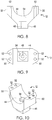
- FIGS. 1 through 14 depict a cycle handlebar mount 10 in accordance with a first embodiment of the present invention.
- FIGS. 15 through 32 depict a cycle handlebar mount 100 in accordance with a second embodiment of the present invention.
- Mounts 10 and 100 are utilized to couple a handlebar 11 to a motorcycle steering mechanism 13 while damping the transmission of vibrations from the cycle steering mechanism to the cycle handlebar.
- mount 10 generally includes bottom brackets 12, a top bracket 14, a pair of sleeves 16, a tension clamp 18 and a clamp bushing 20.
- each of sleeves 16 forms a cylinder and is fabricated from an elastomeric polymer. Suitable polymers from which sleeves 16 can be fabricated include asphaltics, polyurethanes, poly(vinyl acetate) and copolymers, acrylics, natural rubber and styrene-butadiene rubber and silicone rubber. Sleeves 16 are configured for wrapping directly around handlebar 11. The hardness of the sleeves and clamp bushing may vary depending on the desired stiffness of the coupling of the handlebar to the cycle.
- tension clamp 18 includes an upper portion 36 having an inner, half-cylinder surface 37 and a lower portion 38 having an inner, half cylinder surface 39.
- Each of upper portion 36 and lower portion 38 has opposing wing portions 40 with two adjacent, threaded bolts holes 41 for receiving threaded bolts.
- Portions 36, 38 are configured for receiving and clamping handlebar 11 within respective inner, half-cylinder surfaces 37, 39.
- clamping it is meant that portions 36 and 38 hold or secure the handlebar tightly therebetween to prevent movement of the handlebar through the application of inward pressure against the handlebar, which is selectively increased or decreased by tightening or loosening the bolts, as required.
- clamp bushing 20 includes an elongate polymer member, with rounded corners, having pair of adjacent openings 42 therethrough. Openings 42 are configured for receiving and completely surrounding the heads of the pair of bolts used to clamp tension clamp 18 to handlebar 11.
- Clamp bushing 20 is fabricated from an elastomeric polymer. Suitable polymers from which clamp bushing 20 can be fabricated include asphaltics, polyurethanes, poly(vinyl acetate) and copolymers, acrylics, natural rubber and styrene-butadiene rubber and silicone rubber.
- each of bottom brackets 12 has a substantially Y-shaped cross-section, a half-cylinder, inner surface 44, a stem portion 46, a bolt hole 48 extending through stem portion 46 and through inner surface 44, and opposing arms 50 through which a pair of adjacent bolt holes 52 extend.
- a bolt head space 54 is provided within bolt hole 48 for entirely receiving the head of a bolt.
- Stem portion 46 and bolt hole 48 are configured for attaching bottom bracket 12 to motorcycle steering mechanism 13.
- a pair of bottom brackets 12 is attached to motorcycle steering mechanism 13 with a bracket 12 located on either side of tension clamp 18.
- top bracket 14 includes a front face 56, a rear face 58, a top face 59 and a half-cylinder, bottom face 60.
- Top face 59 has a flat portion 61 extending from rear face 58 and an angled portion 62 which extends downwardly from flat portion 61 towards front face 56.
- Adjacent to each end of elongate opening 64 is a bolt hole 66 arranged to receive two bolts.
- Formed within front face 56 is an elongate open slot or indentation 68. Located adjacent to each end of indentation 68 is a pair of bolts holes 70.
- Top bracket 14 is configured for attaching to the pair of bottom brackets 12 and thereby clamping handlebar 11 between the bottom brackets and the upper bracket.
- bottom brackets 12 are attached to motorcycle steering mechanism 13 by inserting threaded bolts 71 through threaded bolt hole 48 of each bottom bracket 12 and complementary bolts holes 72 in steering mechanism 13.
- tension clamp 18 is attached to a center of handlebar 11 by placing the handle bar between the inner, half-cylinder surfaces 37, 39 of upper and lower portions 36, 38, aligning the threaded bolt holes of the wing portions 40 of the upper portion 36 with the lower portion 38 and threading bolts 73 through passageways 41. With tension clamp 18 in place, each end of handlebar 11 is inserted through a sleeve 16, and each sleeve 16 is slid along handlebar 11 until resting adjacent to tension clamp 18.
- handlebar 11 With sleeves 16 and tension clamp 18 securely attached to handlebar 11, handlebar 11 is placed over steering mechanism 13 and sleeves 16 aligned with bottom brackets 12. Handlebar 11 is then lowered so that sleeves 16 are received within the inner surfaces 44 of bottom brackets 12.
- top bracket 14 is positioned over handle bar 11 and bottom brackets 12 and threaded bolts 75 are inserted through bolt holes 66 and 70.
- the threaded bolts 75 are aligned with complimentary threaded bolt holes 52 in bottom bracket 12
- elongate opening 64 is aligned with one of the pair of adjacent bolt heads of the bolts 73 used to attach the upper and lower portions 36, 38 of tension clamp 18
- indentation 86 is aligned with the other pair of adjacent bolt heads of the bolts 73 used to attach the upper and lower portions 36, 38 of tension clamp 18.
- top bracket 14 is lowered with sleeves 16 being sandwiched between the inner half-cylinder surfaces 44 of the bottom brackets 12 and half cylinder surface 60 of the top bracket 14.
- clamp bushing 20 is positioned above elongate opening 64 with openings 42 aligned with the bolts heads of bolts 73 located within elongate opening 64.
- Clamp bushing 20 is then lowered and placed over the bolt heads so that the bolts heads are located within opening 42 of clamp bushing 20.
- Clamp bushing is used to prevent direct contact of the bolt heads to top bracket 14, while allowing indirect interaction between the bolt heads and tension clamp 18 with top bracket 14.
- Mount 10 assembled as described above, serves to isolate handlebar 11 from steering mechanism 13 by preventing a completely rigid coupling of handlebar 11 to the steering mechanism. Instead, rigid couplings are replaced with flexible coupling by virtue of sleeves 16 and clamp bushing 20. Sleeves 16 prevent direct contact between the top bracket and the bottom bracket ⁇ , and the bushing prevents direct contact between the tension clamp and the top bracket. In this manner, the handlebar mount assembly prevents direct and indirect contact of the steering mechanism to the handlebar through the metal components of the handlebar mount assembly.
- FIGS. 15 through 32 depict cycle handlebar mount 100.
- mount 100 generally includes a one-piece bottom bracket 112, a top bracket 114, a pair of sleeves 116, a hinged tension clamp 118 and a clamp bushing 120.
- Each of sleeves 116 forms a cylinder and is fabricated from an elastomeric polymer such as asphaltics, polyurethanes, poly(vinyl acetate) and copolymers, acrylics, natural rubber and styrene-butadiene rubber and silicone rubber.
- Sleeves 116 are configured for wrapping directly around handlebar 11.
- hinged tension clamp 118 includes an upper portion 136 having an inner, half-cylinder surface 137 and a lower portion 138 having an inner, half cylinder surface 137.
- Each of upper portion 136 and lower portion 138 has a wing portion 140 having two adjacent, threaded bolts holes 141 for receiving threaded bolts.
- Opposite each wing portion 140 is a hinge mechanism for hingedly coupling upper portion 136 with lower portion 138.
- upper portion 136 includes a pair of spaced-apart cylinders 139 having aligned passageways 141. The space between cylinders 139 is configured to receive a pivot member 143 of lower portion 138 having a passageway 145 therethrough that aligns with passageways 141.
- a pin 147 is inserted through passageways 141 and passageway 145 thereby hingedly coupling upper and lower portions 136, 138. Protruding upwardly from a central portion of the top surface of the upper portion 136 is a clamp arm 149. Portions 136, 138 are configured for receiving and clamping handlebar 11 within the respective inner, half-cylinder surfaces 137.
- clamp bushing 120 includes an elongate polymer member, with rounded corners, having an opening 142 therethrough. Opening 142 is configured for receiving and completely surrounding clamp arm 149 of clamp tension clamp 118 to handlebar 11.
- Clamp bushing 120 is fabricated from a polymer such asphaltics, polyurethanes, poly(vinyl acetate) and copolymers, acrylics, natural rubber and styrene-butadiene rubber and silicone rubber.
- bottom bracket 112 includes a pair of bracket members 113 connected by a bridge member 115, each of members having a substantially Y-shaped cross-section, a half-cylinder, inner surface 144, a stem portion 146, a bolt hole 148 extending through stem portion 146 and through inner surface 144, and opposing arms 150 through which a pair of adjacent bolt holes 152 extend.
- a bolt head space 154 is provided within bolt hole 148 for receiving the head of a bolt.
- Stem portion 146 and bolt hole 148 are configured for attaching bottom bracket 112 to motorcycle steering mechanism 13.
- a bracket member 113 of bottom brackets 112 is attached to motorcycle steering mechanism 13 on either side of hinged tension clamp 118.
- top bracket 114 includes a front face 156, a rear face 158, a top face 159 and a half-cylinder, bottom face 160.
- Top face 159 has an uppermost flat portion 161 from which curved surfaces 162 and 163 extend toward front face 156 and rear face 158, respectively.
- Curved surface 163 terminates in an elongate footing 157 having two pairs of bolt holes 165 located at opposing ends of footing 157.
- Formed within bottom face 160 is an elongate indention 164.
- Formed within front face 156 is a rectangular-shaped, elongate indentation 168. Located adjacent to each end of indentation 168 is a pair of bolts holes 170.
- Top bracket 114 is configured for attaching to bottom bracket 112 and thereby clamping handlebar 11 between the bottom bracket and the upper bracket.
- bottom bracket 112 is attached to motorcycle steering mechanism 13 by inserting threaded bolts 171 through threaded bolt hole 148 of bottom bracket and complementary bolts holes 172 in the steering mechanism.
- Extension sleeves 175 can be used if it is desired to increase the distance between handlebar 11 and steering mechanism 13.
- tension clamp 118 is attached to a center of handlebar 11 by hingedly coupling upper and lower portions 136, 136 together by aligning passageways 141 with passageway 145 and inserting pin 147 therethrough.
- each end of handlebar 11 is inserted through a sleeve 116, and each sleeve 116 is slid along handlebar 11 until resting adjacent to tension clamp 118.
- handlebar 11 With sleeves 116 and tension clamp 118 securely attached to handlebar 11, handlebar 11 is placed over steering mechanism 13 and sleeves 116 aligned with respective bracket members 113 of bottom brackets 112. Handlebar 11 is then lowered so that a sleeve 116 is received within the inner surface 144 of each bracket member 113 of bottom brackets 112.
- bushing 120 is placed about clamp arm 149 and top bracket 114 is positioned over handle bar 11 and bottom bracket 112 and threaded bolts 175 are inserted through bolt holes 165 and 170.
- the threaded bolts 175 are aligned with complimentary threaded bolt holes 152 in bottom bracket 112, elongate indentation 164 is aligned with bushing 120 and clamp arm 149 of tension clamp 118 and indentation 186 is aligned with the bolt heads of the bolts 173 used to attach the upper and lower portions 136, 138 of tension clamp 118.
- top bracket 114 is lowered with sleeves 116 being sandwiched between the inner half-cylinder surfaces 144 of the bottom brackets 112 and half cylinder surface 160 of the top bracket 114.
- clamp arm 149 including the upper end thereof, is spaced apart from top bracket 114 so that a space is formed therebetween.
- Clamp bushing 120 is located within the space and compressed by and between clamp arm 149 with the sidewalls top bracket 144 which define indentation 186.
- Mount 100 serves to isolate handlebar 11 from steering mechanism 13 by preventing a completely rigid coupling of handlebar 11 to the steering mechanism. Instead, rigid couplings are replaced with flexible coupling by virtue of sleeves 116 and clamp bushing 120.
Landscapes
- Engineering & Computer Science (AREA)
- Mechanical Engineering (AREA)
- Steering Devices For Bicycles And Motorcycles (AREA)
Claims (6)
- Support de guidon de vélo (10) comprenant :un ensemble de patte de fixation supérieure (14 ; 114),un ensemble de patte de fixation inférieure (12 ; 112), etun guidon de vélo (11) autour duquel sont disposés un premier manchon en élastomère (16 ; 116), un second manchon en élastomère (16 ; 116) et un ensemble de serrage en tension (18 ; 118), le guidon de vélo (11) étant couplé fonctionnellement entre l'ensemble de patte de fixation supérieure (14 ; 114) et l'ensemble de patte de fixation inférieure (12, 112),dans lequel le guidon de vélo (11) et l'ensemble de serrage en tension (18, 118) n'entrent pas directement en contact avec l'ensemble de patte de fixation supérieure (14 ; 114) ou l'ensemble de patte de fixation inférieure (12, 112),caractérisé en ce quel'ensemble de serrage en tension (18, 118) comporte une partie de serrage supérieure (36, 136), une partie de serrage inférieure (38, 138) etcomporte en outre une ou plusieurs pinces de serrage (73) couplant la partie de serrage supérieure (36) à la partie de serrage inférieure (38), au moins une des une ou plusieurs pinces de serrage (73) ayant une partie de tête s'étendant à l'intérieur d'un vide défini par une périphérie d'une ouverture (64) s'étendant à travers une paroi supérieure (60) de l'ensemble de patte de fixation supérieure (14), et dans lequel une douille (20) est disposée entre la partie de tête de ladite au moins une des une ou plusieurs pinces de serrage (73) ayant une partie de tête et la périphérie de l'ouverture (64),ou comporte en outre un bras de serrage s'étendant verticalement (149) s'étendant à l'intérieur d'un vide (164) défini en partie par une dépression à l'intérieur d'une surface interne (160) d'une paroi supérieure (159) de l'ensemble de patte de fixation supérieure (114), et dans lequel une douille (120) est disposée autour du bras de serrage (149) et entre le bras de serrage (149) et la surface interne (160) de la paroi supérieure.
- Support de guidon de vélo selon la revendication 1, dans lequel le premier manchon (16, 116) et le second manchon (16, 116) sont comprimés entre l'ensemble de patte de fixation supérieure (14, 114) et l'ensemble de patte de fixation inférieure (12, 112).
- Procédé d'installation d'un guidon de vélo (11) sur un mécanisme de direction de vélo (13) comprenant :la fixation d'une patte de fixation inférieure (112, 12) au mécanisme de direction de vélo (13),la disposition d'un premier manchon élastomère (116, 16) et d'un second manchon élastomère (116, 16) autour du guidon de vélo (11),le serrage d'un ensemble de serrage en tension (118, 18) autour du guidon de vélo (11) et entre le premier manchon (116, 16) et le second manchon (116, 16), etle placement du guidon de vélo (11) dans la patte de fixation inférieure (112, 12), le premier manchon (116, 16) et le second manchon (116, 16) étant en contact avec la patte de fixation inférieure (112, 12) et le guidon de vélo (11) et l'ensemble de serrage en tension (118, 18) étant espacés de la patte de fixation inférieure (112, 12), etla fixation d'une patte de fixation supérieure (114, 14) à la patte de fixation inférieure (112, 12), le premier manchon (116, 16) et le second manchon (116, 16) étant comprimés entre la patte de fixation inférieure (112, 12) et la patte de fixation supérieure (114, 14) et le guidon de vélo (11) et l'ensemble serrage en tension (118, 18) étant espacé de la patte de fixation supérieure (114, 14), dans lequel le procédé comprend en outre le placement d'une douille (120) entre l'ensemble de serrage en tension (118, 18) et la patte de fixation supérieure (114, 14).
- Procédé selon la revendication 3 comprenant le placement de la douille (120) à l'intérieur d'un vide défini au moins en partie par la patte de fixation supérieure (114, 14).
- Procédé selon la revendication 3 comprenant le placement de la douille (120) autour d'une pince d'ensemble de serrage en tension (118, 18) qui s'étend dans le vide de sorte que la douille (120) s'étende vers et entre la pince et la patte de fixation supérieure (114, 14).
- Procédé selon la revendication 3 comprenant le placement de la douille (120) autour d'un bras d'ensemble de serrage en tension (118, 18) qui s'étend dans le vide de sorte que la douille (120) s'étende vers et entre la pince et la patte de fixation supérieure (114, 14).
Applications Claiming Priority (3)
| Application Number | Priority Date | Filing Date | Title |
|---|---|---|---|
| US201662295595P | 2016-02-16 | 2016-02-16 | |
| US15/224,408 US10207766B2 (en) | 2016-02-16 | 2016-07-29 | Handlebar mount assembly |
| PCT/US2017/017949 WO2017142936A1 (fr) | 2016-02-16 | 2017-02-15 | Ensemble monture de guidon |
Publications (3)
| Publication Number | Publication Date |
|---|---|
| EP3416879A1 EP3416879A1 (fr) | 2018-12-26 |
| EP3416879A4 EP3416879A4 (fr) | 2019-11-13 |
| EP3416879B1 true EP3416879B1 (fr) | 2021-11-03 |
Family
ID=59560562
Family Applications (1)
| Application Number | Title | Priority Date | Filing Date |
|---|---|---|---|
| EP17753748.7A Active EP3416879B1 (fr) | 2016-02-16 | 2017-02-15 | Ensemble monture de guidon |
Country Status (5)
| Country | Link |
|---|---|
| US (2) | US10207766B2 (fr) |
| EP (1) | EP3416879B1 (fr) |
| AU (1) | AU2017221309B2 (fr) |
| CA (1) | CA3014786C (fr) |
| WO (1) | WO2017142936A1 (fr) |
Families Citing this family (9)
| Publication number | Priority date | Publication date | Assignee | Title |
|---|---|---|---|---|
| US10207766B2 (en) * | 2016-02-16 | 2019-02-19 | Lance Smith | Handlebar mount assembly |
| US10556546B2 (en) * | 2017-04-21 | 2020-02-11 | Thomas Burton | Tube mounts for use on tubular features of vehicles to mount a variety of vehicle accessories |
| USD920854S1 (en) * | 2020-01-24 | 2021-06-01 | Super73, Inc. | Motorbike handlebar clamp mechanism |
| US20220018371A1 (en) * | 2020-07-16 | 2022-01-20 | T-Rex Tracking Corporation | Clamping bimetal non-keyed shaft collar with radial mounts |
| USD1017390S1 (en) * | 2020-12-23 | 2024-03-12 | Valmont Industries, Inc. | Reversible saddle for driveline coupler |
| US11608870B2 (en) * | 2021-02-24 | 2023-03-21 | Urmosi & Spaulding, LLC | Shock and vibration isolating handlebar mounting system |
| USD1027749S1 (en) * | 2021-12-15 | 2024-05-21 | Kids Ride Shotgun Limited | Handlebar |
| USD1004411S1 (en) * | 2022-03-02 | 2023-11-14 | Lowbrow Customs, Llc | Springer fork clamp |
| US12552292B1 (en) * | 2024-01-25 | 2026-02-17 | Lance Smith | Motor vehicle seat mounting system |
Family Cites Families (21)
| Publication number | Priority date | Publication date | Assignee | Title |
|---|---|---|---|---|
| GB419336A (en) | 1933-11-28 | 1934-11-09 | Norton Motors Ltd | Improvements in or relating to handle-bars for cycles, motor-cycles, and the like |
| US2396041A (en) * | 1944-12-21 | 1946-03-05 | Indian Motocycle Company | Resilient mounting for handle bars |
| US4616949A (en) * | 1983-12-13 | 1986-10-14 | Andrew Kellner | Steering knuckle for a velocipede |
| CH671742A5 (en) * | 1986-09-08 | 1989-09-29 | Pletscher Geb | Accessory fastener for bicycle frames - with clamp shoes with concave clamp surface for tubing |
| US5829316A (en) * | 1996-11-05 | 1998-11-03 | Answer Products, Inc. | Universal mount for mounting a handlebar on existing stock handlebar clamps of motorcycles or comparable vehicles |
| JP4232997B2 (ja) * | 1999-03-31 | 2009-03-04 | 本田技研工業株式会社 | 自動二輪車の操舵装置 |
| US6712541B1 (en) * | 2000-12-05 | 2004-03-30 | Research Group Three Inc. | Multi-post shock absorber clamp system |
| US6953201B1 (en) * | 2003-05-14 | 2005-10-11 | Vandemortel Dennis R | Cycle handlebar shock and vibration damper |
| US20080203699A1 (en) * | 2003-09-30 | 2008-08-28 | Rich Orin Truchinski | Handlebar mount shock absorber structure |
| GB0405535D0 (en) * | 2004-03-12 | 2004-04-21 | Renthal Ltd | Handlebar clamp |
| DE102004046158B4 (de) * | 2004-09-23 | 2006-07-27 | Gröbner Fertigungs GmbH | Vorrichtung zur Halterung eines Lenkers |
| US8215203B1 (en) * | 2006-02-01 | 2012-07-10 | Paul Swift | Handlebar clamp to accommodate a multiplicity of handlebars for a bicycle having a handlebar post and a transverse clamping plate |
| FR2899867B1 (fr) | 2006-04-14 | 2008-12-19 | Lagar Concept Sarl | Dispositif pour la filtration des vibrations et des chocs sur un guidon de vehicule |
| TWM298560U (en) * | 2006-05-04 | 2006-10-01 | Guo-Ping He | Clamping structure for rod members with different diameters |
| US7699331B2 (en) * | 2007-05-18 | 2010-04-20 | Mcvickar Matthew | Motorcycle-stance alteration kit |
| DE102008052762A1 (de) * | 2008-10-22 | 2010-04-29 | Bayerische Motoren Werke Aktiengesellschaft | Lenker für Fahrzeuge, insbesondere für Motorräder |
| US9061728B2 (en) | 2010-03-12 | 2015-06-23 | Trek Bicycle Corporation | Bicycle handlebar and grip assembly |
| US8317214B2 (en) * | 2010-03-30 | 2012-11-27 | George John Athanasiou | Shock and vibration damping handlebar mounting assembly |
| FR2961165B1 (fr) * | 2010-06-15 | 2012-07-06 | Gilbert Mecanique | Dispositif d'amortissement de chocs pour vehicule. |
| JP6178822B2 (ja) * | 2015-09-11 | 2017-08-09 | 本田技研工業株式会社 | 鞍乗り型車両のステアリング構造 |
| US10207766B2 (en) * | 2016-02-16 | 2019-02-19 | Lance Smith | Handlebar mount assembly |
-
2016
- 2016-07-29 US US15/224,408 patent/US10207766B2/en active Active
-
2017
- 2017-02-15 AU AU2017221309A patent/AU2017221309B2/en active Active
- 2017-02-15 WO PCT/US2017/017949 patent/WO2017142936A1/fr not_active Ceased
- 2017-02-15 CA CA3014786A patent/CA3014786C/fr active Active
- 2017-02-15 EP EP17753748.7A patent/EP3416879B1/fr active Active
-
2019
- 2019-01-08 US US16/242,698 patent/US10710668B2/en active Active
Non-Patent Citations (1)
| Title |
|---|
| None * |
Also Published As
| Publication number | Publication date |
|---|---|
| US10710668B2 (en) | 2020-07-14 |
| CA3014786A1 (fr) | 2017-08-24 |
| AU2017221309B2 (en) | 2019-09-12 |
| WO2017142936A1 (fr) | 2017-08-24 |
| US10207766B2 (en) | 2019-02-19 |
| CA3014786C (fr) | 2020-03-24 |
| EP3416879A4 (fr) | 2019-11-13 |
| AU2017221309A1 (en) | 2018-09-06 |
| US20170233030A1 (en) | 2017-08-17 |
| US20190144067A1 (en) | 2019-05-16 |
| EP3416879A1 (fr) | 2018-12-26 |
Similar Documents
| Publication | Publication Date | Title |
|---|---|---|
| EP3416879B1 (fr) | Ensemble monture de guidon | |
| US6953201B1 (en) | Cycle handlebar shock and vibration damper | |
| US9604690B2 (en) | Bicycle frame with coupling device to permit flexing | |
| US8317214B2 (en) | Shock and vibration damping handlebar mounting assembly | |
| US8403350B2 (en) | Seatstay suspension mount | |
| AU2016334365A1 (en) | Shock absorbing grip assembly | |
| TWI763622B (zh) | 具有柔緩性座墊支柱介面之自行車 | |
| US6575485B2 (en) | Suspension system for a bicycle trailer | |
| US4269445A (en) | Windshield mounting assembly | |
| US6988740B2 (en) | Suspension for bicycle seat and handlebar support | |
| CN115485188A (zh) | 自行车悬架的系统和方法 | |
| JP2000072077A (ja) | 二輪車のハンドル支持構造 | |
| US7494142B2 (en) | Swing arm with impact dampener | |
| US7540516B2 (en) | Machine for a floating handlebar system | |
| US20210163092A1 (en) | Bicycle with compliant seat post interface | |
| WO2014074172A1 (fr) | Système de guidon | |
| US4226463A (en) | Windshield mounting assembly | |
| US7862063B2 (en) | Bicycle frame composed with convoluted curves | |
| WO2000021824A1 (fr) | Systeme de guidon | |
| US20160159426A1 (en) | Vibration-damping handlebar assembly | |
| US20050247160A1 (en) | Vibration reducing link | |
| EP1985531B1 (fr) | Cadre de bicyclette | |
| CA2513171C (fr) | Bras oscillant avec amortisseur de chocs |
Legal Events
| Date | Code | Title | Description |
|---|---|---|---|
| STAA | Information on the status of an ep patent application or granted ep patent |
Free format text: STATUS: THE INTERNATIONAL PUBLICATION HAS BEEN MADE |
|
| PUAI | Public reference made under article 153(3) epc to a published international application that has entered the european phase |
Free format text: ORIGINAL CODE: 0009012 |
|
| STAA | Information on the status of an ep patent application or granted ep patent |
Free format text: STATUS: REQUEST FOR EXAMINATION WAS MADE |
|
| 17P | Request for examination filed |
Effective date: 20180827 |
|
| AK | Designated contracting states |
Kind code of ref document: A1 Designated state(s): AL AT BE BG CH CY CZ DE DK EE ES FI FR GB GR HR HU IE IS IT LI LT LU LV MC MK MT NL NO PL PT RO RS SE SI SK SM TR |
|
| AX | Request for extension of the european patent |
Extension state: BA ME |
|
| DAV | Request for validation of the european patent (deleted) | ||
| DAX | Request for extension of the european patent (deleted) | ||
| A4 | Supplementary search report drawn up and despatched |
Effective date: 20191014 |
|
| RIC1 | Information provided on ipc code assigned before grant |
Ipc: B62K 21/14 20060101ALI20191008BHEP Ipc: F16F 15/00 20060101ALI20191008BHEP Ipc: B62K 21/08 20060101AFI20191008BHEP Ipc: B62K 21/20 20060101ALI20191008BHEP |
|
| STAA | Information on the status of an ep patent application or granted ep patent |
Free format text: STATUS: EXAMINATION IS IN PROGRESS |
|
| 17Q | First examination report despatched |
Effective date: 20200810 |
|
| REG | Reference to a national code |
Ref country code: DE Ref legal event code: R079 Ref document number: 602017048726 Country of ref document: DE Free format text: PREVIOUS MAIN CLASS: B62K0021080000 Ipc: F16F0015000000 |
|
| RIC1 | Information provided on ipc code assigned before grant |
Ipc: G06Q 50/18 20120101ALN20210330BHEP Ipc: B62K 21/14 20060101ALI20210330BHEP Ipc: B62K 21/20 20060101ALI20210330BHEP Ipc: F16F 15/00 20060101ALI20210330BHEP Ipc: B62K 21/08 20060101AFI20210330BHEP |
|
| GRAP | Despatch of communication of intention to grant a patent |
Free format text: ORIGINAL CODE: EPIDOSNIGR1 |
|
| STAA | Information on the status of an ep patent application or granted ep patent |
Free format text: STATUS: GRANT OF PATENT IS INTENDED |
|
| RIC1 | Information provided on ipc code assigned before grant |
Ipc: G06Q 50/18 20120101ALN20210419BHEP Ipc: B62K 21/14 20060101ALI20210419BHEP Ipc: B62K 21/20 20060101ALI20210419BHEP Ipc: F16F 15/00 20060101AFI20210419BHEP |
|
| INTG | Intention to grant announced |
Effective date: 20210517 |
|
| GRAS | Grant fee paid |
Free format text: ORIGINAL CODE: EPIDOSNIGR3 |
|
| GRAA | (expected) grant |
Free format text: ORIGINAL CODE: 0009210 |
|
| STAA | Information on the status of an ep patent application or granted ep patent |
Free format text: STATUS: THE PATENT HAS BEEN GRANTED |
|
| AK | Designated contracting states |
Kind code of ref document: B1 Designated state(s): AL AT BE BG CH CY CZ DE DK EE ES FI FR GB GR HR HU IE IS IT LI LT LU LV MC MK MT NL NO PL PT RO RS SE SI SK SM TR |
|
| REG | Reference to a national code |
Ref country code: GB Ref legal event code: FG4D |
|
| REG | Reference to a national code |
Ref country code: AT Ref legal event code: REF Ref document number: 1444222 Country of ref document: AT Kind code of ref document: T Effective date: 20211115 Ref country code: CH Ref legal event code: EP |
|
| REG | Reference to a national code |
Ref country code: IE Ref legal event code: FG4D |
|
| REG | Reference to a national code |
Ref country code: DE Ref legal event code: R096 Ref document number: 602017048726 Country of ref document: DE |
|
| REG | Reference to a national code |
Ref country code: LT Ref legal event code: MG9D |
|
| REG | Reference to a national code |
Ref country code: NL Ref legal event code: MP Effective date: 20211103 |
|
| PG25 | Lapsed in a contracting state [announced via postgrant information from national office to epo] |
Ref country code: RS Free format text: LAPSE BECAUSE OF FAILURE TO SUBMIT A TRANSLATION OF THE DESCRIPTION OR TO PAY THE FEE WITHIN THE PRESCRIBED TIME-LIMIT Effective date: 20211103 Ref country code: LT Free format text: LAPSE BECAUSE OF FAILURE TO SUBMIT A TRANSLATION OF THE DESCRIPTION OR TO PAY THE FEE WITHIN THE PRESCRIBED TIME-LIMIT Effective date: 20211103 Ref country code: FI Free format text: LAPSE BECAUSE OF FAILURE TO SUBMIT A TRANSLATION OF THE DESCRIPTION OR TO PAY THE FEE WITHIN THE PRESCRIBED TIME-LIMIT Effective date: 20211103 Ref country code: BG Free format text: LAPSE BECAUSE OF FAILURE TO SUBMIT A TRANSLATION OF THE DESCRIPTION OR TO PAY THE FEE WITHIN THE PRESCRIBED TIME-LIMIT Effective date: 20220203 |
|
| PG25 | Lapsed in a contracting state [announced via postgrant information from national office to epo] |
Ref country code: IS Free format text: LAPSE BECAUSE OF FAILURE TO SUBMIT A TRANSLATION OF THE DESCRIPTION OR TO PAY THE FEE WITHIN THE PRESCRIBED TIME-LIMIT Effective date: 20220303 Ref country code: SE Free format text: LAPSE BECAUSE OF FAILURE TO SUBMIT A TRANSLATION OF THE DESCRIPTION OR TO PAY THE FEE WITHIN THE PRESCRIBED TIME-LIMIT Effective date: 20211103 Ref country code: PT Free format text: LAPSE BECAUSE OF FAILURE TO SUBMIT A TRANSLATION OF THE DESCRIPTION OR TO PAY THE FEE WITHIN THE PRESCRIBED TIME-LIMIT Effective date: 20220303 Ref country code: PL Free format text: LAPSE BECAUSE OF FAILURE TO SUBMIT A TRANSLATION OF THE DESCRIPTION OR TO PAY THE FEE WITHIN THE PRESCRIBED TIME-LIMIT Effective date: 20211103 Ref country code: NO Free format text: LAPSE BECAUSE OF FAILURE TO SUBMIT A TRANSLATION OF THE DESCRIPTION OR TO PAY THE FEE WITHIN THE PRESCRIBED TIME-LIMIT Effective date: 20220203 Ref country code: NL Free format text: LAPSE BECAUSE OF FAILURE TO SUBMIT A TRANSLATION OF THE DESCRIPTION OR TO PAY THE FEE WITHIN THE PRESCRIBED TIME-LIMIT Effective date: 20211103 Ref country code: LV Free format text: LAPSE BECAUSE OF FAILURE TO SUBMIT A TRANSLATION OF THE DESCRIPTION OR TO PAY THE FEE WITHIN THE PRESCRIBED TIME-LIMIT Effective date: 20211103 Ref country code: HR Free format text: LAPSE BECAUSE OF FAILURE TO SUBMIT A TRANSLATION OF THE DESCRIPTION OR TO PAY THE FEE WITHIN THE PRESCRIBED TIME-LIMIT Effective date: 20211103 Ref country code: GR Free format text: LAPSE BECAUSE OF FAILURE TO SUBMIT A TRANSLATION OF THE DESCRIPTION OR TO PAY THE FEE WITHIN THE PRESCRIBED TIME-LIMIT Effective date: 20220204 Ref country code: ES Free format text: LAPSE BECAUSE OF FAILURE TO SUBMIT A TRANSLATION OF THE DESCRIPTION OR TO PAY THE FEE WITHIN THE PRESCRIBED TIME-LIMIT Effective date: 20211103 |
|
| PG25 | Lapsed in a contracting state [announced via postgrant information from national office to epo] |
Ref country code: SM Free format text: LAPSE BECAUSE OF FAILURE TO SUBMIT A TRANSLATION OF THE DESCRIPTION OR TO PAY THE FEE WITHIN THE PRESCRIBED TIME-LIMIT Effective date: 20211103 Ref country code: SK Free format text: LAPSE BECAUSE OF FAILURE TO SUBMIT A TRANSLATION OF THE DESCRIPTION OR TO PAY THE FEE WITHIN THE PRESCRIBED TIME-LIMIT Effective date: 20211103 Ref country code: RO Free format text: LAPSE BECAUSE OF FAILURE TO SUBMIT A TRANSLATION OF THE DESCRIPTION OR TO PAY THE FEE WITHIN THE PRESCRIBED TIME-LIMIT Effective date: 20211103 Ref country code: EE Free format text: LAPSE BECAUSE OF FAILURE TO SUBMIT A TRANSLATION OF THE DESCRIPTION OR TO PAY THE FEE WITHIN THE PRESCRIBED TIME-LIMIT Effective date: 20211103 Ref country code: DK Free format text: LAPSE BECAUSE OF FAILURE TO SUBMIT A TRANSLATION OF THE DESCRIPTION OR TO PAY THE FEE WITHIN THE PRESCRIBED TIME-LIMIT Effective date: 20211103 Ref country code: CZ Free format text: LAPSE BECAUSE OF FAILURE TO SUBMIT A TRANSLATION OF THE DESCRIPTION OR TO PAY THE FEE WITHIN THE PRESCRIBED TIME-LIMIT Effective date: 20211103 |
|
| REG | Reference to a national code |
Ref country code: DE Ref legal event code: R097 Ref document number: 602017048726 Country of ref document: DE |
|
| PLBE | No opposition filed within time limit |
Free format text: ORIGINAL CODE: 0009261 |
|
| STAA | Information on the status of an ep patent application or granted ep patent |
Free format text: STATUS: NO OPPOSITION FILED WITHIN TIME LIMIT |
|
| PG25 | Lapsed in a contracting state [announced via postgrant information from national office to epo] |
Ref country code: MC Free format text: LAPSE BECAUSE OF FAILURE TO SUBMIT A TRANSLATION OF THE DESCRIPTION OR TO PAY THE FEE WITHIN THE PRESCRIBED TIME-LIMIT Effective date: 20211103 |
|
| 26N | No opposition filed |
Effective date: 20220804 |
|
| REG | Reference to a national code |
Ref country code: CH Ref legal event code: PL |
|
| PG25 | Lapsed in a contracting state [announced via postgrant information from national office to epo] |
Ref country code: LU Free format text: LAPSE BECAUSE OF NON-PAYMENT OF DUE FEES Effective date: 20220215 Ref country code: AL Free format text: LAPSE BECAUSE OF FAILURE TO SUBMIT A TRANSLATION OF THE DESCRIPTION OR TO PAY THE FEE WITHIN THE PRESCRIBED TIME-LIMIT Effective date: 20211103 |
|
| PG25 | Lapsed in a contracting state [announced via postgrant information from national office to epo] |
Ref country code: SI Free format text: LAPSE BECAUSE OF FAILURE TO SUBMIT A TRANSLATION OF THE DESCRIPTION OR TO PAY THE FEE WITHIN THE PRESCRIBED TIME-LIMIT Effective date: 20211103 |
|
| PG25 | Lapsed in a contracting state [announced via postgrant information from national office to epo] |
Ref country code: LI Free format text: LAPSE BECAUSE OF NON-PAYMENT OF DUE FEES Effective date: 20220228 Ref country code: IE Free format text: LAPSE BECAUSE OF NON-PAYMENT OF DUE FEES Effective date: 20220215 Ref country code: CH Free format text: LAPSE BECAUSE OF NON-PAYMENT OF DUE FEES Effective date: 20220228 |
|
| PG25 | Lapsed in a contracting state [announced via postgrant information from national office to epo] |
Ref country code: IT Free format text: LAPSE BECAUSE OF FAILURE TO SUBMIT A TRANSLATION OF THE DESCRIPTION OR TO PAY THE FEE WITHIN THE PRESCRIBED TIME-LIMIT Effective date: 20211103 |
|
| REG | Reference to a national code |
Ref country code: AT Ref legal event code: UEP Ref document number: 1444222 Country of ref document: AT Kind code of ref document: T Effective date: 20211103 |
|
| P01 | Opt-out of the competence of the unified patent court (upc) registered |
Effective date: 20230526 |
|
| PG25 | Lapsed in a contracting state [announced via postgrant information from national office to epo] |
Ref country code: HU Free format text: LAPSE BECAUSE OF FAILURE TO SUBMIT A TRANSLATION OF THE DESCRIPTION OR TO PAY THE FEE WITHIN THE PRESCRIBED TIME-LIMIT; INVALID AB INITIO Effective date: 20170215 |
|
| PG25 | Lapsed in a contracting state [announced via postgrant information from national office to epo] |
Ref country code: MK Free format text: LAPSE BECAUSE OF FAILURE TO SUBMIT A TRANSLATION OF THE DESCRIPTION OR TO PAY THE FEE WITHIN THE PRESCRIBED TIME-LIMIT Effective date: 20211103 Ref country code: CY Free format text: LAPSE BECAUSE OF FAILURE TO SUBMIT A TRANSLATION OF THE DESCRIPTION OR TO PAY THE FEE WITHIN THE PRESCRIBED TIME-LIMIT Effective date: 20211103 |
|
| PG25 | Lapsed in a contracting state [announced via postgrant information from national office to epo] |
Ref country code: MT Free format text: LAPSE BECAUSE OF FAILURE TO SUBMIT A TRANSLATION OF THE DESCRIPTION OR TO PAY THE FEE WITHIN THE PRESCRIBED TIME-LIMIT Effective date: 20211103 |
|
| PG25 | Lapsed in a contracting state [announced via postgrant information from national office to epo] |
Ref country code: TR Free format text: LAPSE BECAUSE OF FAILURE TO SUBMIT A TRANSLATION OF THE DESCRIPTION OR TO PAY THE FEE WITHIN THE PRESCRIBED TIME-LIMIT Effective date: 20211103 |
|
| PGFP | Annual fee paid to national office [announced via postgrant information from national office to epo] |
Ref country code: GB Payment date: 20260227 Year of fee payment: 10 |
|
| PGFP | Annual fee paid to national office [announced via postgrant information from national office to epo] |
Ref country code: DE Payment date: 20260227 Year of fee payment: 10 |
|
| PGFP | Annual fee paid to national office [announced via postgrant information from national office to epo] |
Ref country code: AT Payment date: 20260227 Year of fee payment: 10 |
|
| PGFP | Annual fee paid to national office [announced via postgrant information from national office to epo] |
Ref country code: BE Payment date: 20260227 Year of fee payment: 10 |
|
| PGFP | Annual fee paid to national office [announced via postgrant information from national office to epo] |
Ref country code: FR Payment date: 20260225 Year of fee payment: 10 |