EP3417143B1 - Système de traitement de puits de forage - Google Patents
Système de traitement de puits de forage Download PDFInfo
- Publication number
- EP3417143B1 EP3417143B1 EP17753921.0A EP17753921A EP3417143B1 EP 3417143 B1 EP3417143 B1 EP 3417143B1 EP 17753921 A EP17753921 A EP 17753921A EP 3417143 B1 EP3417143 B1 EP 3417143B1
- Authority
- EP
- European Patent Office
- Prior art keywords
- wellbore
- energetic material
- explosive
- downhole tool
- acid
- Prior art date
- Legal status (The legal status is an assumption and is not a legal conclusion. Google has not performed a legal analysis and makes no representation as to the accuracy of the status listed.)
- Active
Links
Images
Classifications
-
- E—FIXED CONSTRUCTIONS
- E21—EARTH OR ROCK DRILLING; MINING
- E21B—EARTH OR ROCK DRILLING; OBTAINING OIL, GAS, WATER, SOLUBLE OR MELTABLE MATERIALS OR A SLURRY OF MINERALS FROM WELLS
- E21B43/00—Methods or apparatus for obtaining oil, gas, water, soluble or meltable materials or a slurry of minerals from wells
- E21B43/11—Perforators; Permeators
- E21B43/116—Gun or shaped-charge perforators
- E21B43/117—Shaped-charge perforators
-
- E—FIXED CONSTRUCTIONS
- E21—EARTH OR ROCK DRILLING; MINING
- E21B—EARTH OR ROCK DRILLING; OBTAINING OIL, GAS, WATER, SOLUBLE OR MELTABLE MATERIALS OR A SLURRY OF MINERALS FROM WELLS
- E21B43/00—Methods or apparatus for obtaining oil, gas, water, soluble or meltable materials or a slurry of minerals from wells
- E21B43/25—Methods for stimulating production
Definitions
- the present disclosure relates in general to a system and method of treating a subterranean wellbore. More specifically, the present disclosure relates to coupling a well treatment substance with energetic material and reacting the energetic material within a wellbore.
- Perforating systems are used for the purpose, among others, of making hydraulic communication passages, called perforations, in wellbores drilled through earth formations so that predetermined zones of the earth formations can be hydraulically connected to the wellbore.
- Perforations are needed because wellbores are typically lined with a string of casing and cement is generally pumped into the annular space between the wellbore wall and the casing.
- Reasons for cementing the casing against the wellbore wall includes retaining the casing in the wellbore and hydraulically isolating various earth formations penetrated by the wellbore.
- an inner casing string is included that is circumscribed by the casing. Without the perforations oil/gas from the formation surrounding the wellbore cannot make its way to production tubing inserted into the wellbore within the casing.
- Perforating systems typically include one or more perforating guns connected together in series to form a perforating gun string, which can sometimes surpass a thousand feet of perforating length.
- the gun strings are usually lowered into a wellbore on a wireline or tubing, where the individual perforating guns are generally coupled together by connector subs.
- Included with the perforating gun are shaped charges that typically include a housing, a liner, and a quantity of high explosive inserted between the liner and the housing.
- Different kinds of perforating guns are disclosed for example in US2013192829 and WO2016022111 .
- the force of the detonation collapses the liner and ejects it from one end of the charge at very high velocity in a pattern called a jet that perforates the casing and the cement and creates a perforation that extends into the surrounding formation.
- Each shaped charge is typically attached to a detonation cord that runs axially within each of the guns.
- Wellbore perforating sometimes is typically followed by hydraulic fracturing in order to promote production from the surrounding formation.
- the extreme pressures generated by the perforating jet often crush and compacts the reservoir rock around each of the perforations; which typically impedes inflow or injection to and from the reservoir.
- the crushed zone can reduce the effective permeability of the reservoir rock by up to 75%. Acid is sometimes used to break down this crushed and compacted rock, and is usually pumped from surface and injected into the perforations.
- One example method includes deploying a downhole tool in the wellbore, where the downhole tool includes an additive casting made up of an energetic material and a crystalline anhydrous acid.
- the downhole tool is positioned adjacent an opening formed in a sidewall of the wellbore, and a reaction of the energetic material is caused to generate an expanding gas that drives the crystalline anhydrous acid into the opening thereby increasing a flow of hydrocarbons through the opening.
- the downhole tool can further include an explosive, and wherein the step of causing a reaction of the energetic material involves initiating detonation of the explosive so that detonation products of the explosive contact the energetic material at a temperature to initiate reaction of the energetic material.
- the energetic material is activated concurrent with forming perforations in a sidewall of the wellbore, so that the treatment substance is forced into the perforations by expanding gases created by activation of the energetic material.
- the downhole tool includes a perforating gun, and wherein the explosive comprises high explosive disposed in a plurality of shaped charges that are set radially inward from the additive casting, so that when high explosive in the shaped charges are detonated, detonation products are generated from detonation of the high explosive that contact the energetic material at a temperature to initiate reaction of the energetic material.
- detonation of the shaped charges form perforations in a sidewall of the wellbore, wherein a plurality of openings are formed in the sidewall of the wellbore, and wherein the perforations define the openings
- the additive casting is formed into an annular member that circumscribes a portion of the tool.
- the additive casting is formed into a planar member and disposed inside a body of the tool.
- the acid optionally dissolves rock inside of the opening.
- the energetic material can be a propellant.
- a downhole tool for use in operations in a wellbore and that is made up of a housing, explosive in the housing and that is strategically oriented, so that when the explosive is detonated, detonation products are formed that travel along a designated path, and an additive casting that is intersected by the designated path, the additive casting formed from a solid matrix of a settable material, and an energetic material, and where a wellbore treatment material is embedded within the settable material, so that when a reaction in the energetic material is initiated in the wellbore, the wellbore treatment material is released into the wellbore.
- the wellbore treatment fluid can be an anhydrous crystalline acid that is reactive with rock that is intersected by a downhole perforation.
- the energetic material includes a substance that produces energy or pressurized gas when reacted and is selected from the group consisting of a propellant, an oxidizer, ammonium perchlorate, potassium perchlorate, and combinations thereof.
- An example of the housing is a perforating gun body, wherein the explosive comprises a high explosive within a shaped charge, and wherein detonating the high explosive forms openings in a sidewall of the wellbore.
- One embodiment of the additive casting is an annular member coupled with the housing.
- the downhole tool can further include a controller in communication with the explosive.
- Another method of wellbore operations includes disposing an additive casting in the wellbore, the additive casting formed from an energetic material and wellbore treatment material combined in a solid matrix, and introducing the wellbore treatment material into an opening in a sidewall of the wellbore by initiating a reaction of the energetic material that releases the wellbore treatment material from the matrix, and generates a gas that drives the wellbore treatment material into the opening.
- the method can further include forming the opening by detonating a shaped charge downhole that is oriented to the sidewall.
- the additive casting is disposed in a path of detonation product discharged from the shaped charge, and wherein the detonation product is at a temperature that initiates the reaction of the energetic material.
- the wellbore treatment material is a crystalline anhydrous acid that when in the wellbore reconstitutes as a liquid and reacts with rock inside of the opening.
- An example of the reactive material is a propellant.
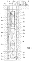
- FIG. 1 An example of a well treatment system 10 is shown in a partial side sectional view in Figure 1 .
- the system 10 is used for treating a wellbore 12 that intersects a formation 14.
- Wellbore 12 is lined with casing 16 which forms a barrier between formation 14 and inside of wellbore 12.
- a perforating string 18 shown made up of a string of perforating guns 20 1 -20 n , optional connector subs 22 1 , 22 2 couple together adjacent guns 20 1 -20 n .
- the guns 20 1 -20 n of the illustrated embodiment include elongate gun bodies 24 1 -24 n that have a generally curved outer surface and resemble a cylindrical shape.
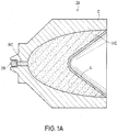
- Charge tubes 26 1 -26 n are depicted disposed within each of the gun bodies 24 1 -24 n . Further in the example of Figure 1 , shaped charges 28 are shown mounted within the charge tubes 26 1 -26 n . Shown in a side sectional view in Figure 1A is an embodiment of a shaped charge 28, and which includes a case C, a liner L set in the case C, and high explosive HE between the case C and liner L. A detonating cord 29 extends within the perforating string 18 ( Figure 1 ) and along a path that runs adjacent a booster charge BC in each of the shaped charges 28.
- Example high explosives HE include compositions sold under trade designations HMX, HNS, RDX, PYX and TNAZ.
- a wireline 32 is shown mounted to an upper end of a perforating string 18 and is used for raising and lowering perforating string 18 within wellbore 12. Additionally, wireline 32 can provide a communication means between perforating string 18 and a surface truck 33 shown mounted on surface 34 and outside of the wellbore 12. In one alternative, a controller 35 is included, such as in surface truck 33, and that is in selective communication with wireline 32 for controlling operation of perforating string 18. In an optional embodiment, wireline 32 couples to a motorized reel (not shown) for raising/lowering wireline 32 in wellbore 12.
- perforating string 18 communicates to surface truck 33 and/or controller 35 via wireline 32.
- other means of conveying and signaling perforating string 18 may be employed, such as coiled tubing, cables, slick line, and the like.
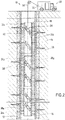
- Figure 2 shows in a side partial sectional view an example of the shaped charges 28 of Figure 1 having been detonated, such as from a signal via wireline 32 from surface truck 33 or controller 35, and which have formed perforations 36 that project radially out from the wellbore 12, through the casing 16, and into the formation 14. Openings 38 in the sidewall of each of the gun bodies 24 1 -24 n are also formed by detonating the shaped charges 28.
- the additive castings 30 1 -30 n are substantially solid members whose constituents include an energetic material and a treatment substance.
- Examples of the energetic material include any substance that produces energy or pressurized gas when reacted, such as a propellant, oxidizers, ammonium perchlorate, potassium perchlorate, any other reactive material, and combinations thereof.
- Examples of the treatment substance include anything used for treating the wellbore 12, such as an acid, crystalline acids, anhydrous acids, crystalline anhydrous acids, brine, a surfactant, a salt, a polysaccharide, corrosion inhibitors, and combinations thereof.
- suitable crystalline anhydrous acids and salts that produce acids when dissolved include, but are not intended to be limited to, acetic anhydride, citric acid anhydride, sulfamic acid anhydride, benzoic acid, benzoic acid flakes, hydrochloric acid, hydrofluoric acid, phthalic acid, phthalic anhydride, terephthalic acid, terephthalic anhydride, sulfuric acid anhydride, polylactic acid, boric acid, ammonium bifluoride, potassium bifluoride, ethylenediaminetetraacetic acid, lactic acid, along with combinations and mixtures thereof.
- the treatment substance is encapsulated in a shell (not shown) that dissolves/degrades when exposed to conditions/fluids downhole.
- a shell not shown
- the treatment substances dissolve in connate fluid, water based drilling fluids, oil based drilling fluids, and combinations thereof.
- the shaped charges 28 of Figure 1 are oriented so that when explosives within the shaped charges 28 are detonated, detonation products generated by the detonation are directed towards the additive casting 30 1 -30 n .
- An example of the detonation products includes gas at high pressure and or temperature that initiate a corresponding reaction of the energetic material in the additive casting 30 1 -30 n . Reacting the energetic material releases the treatment substance from the additive casting 30 1 -30 n . and into the wellbore 12.
- the treatment substance takes the form of a treatment fluid 40 when released from the castings 30 1 -30 n .
- the treatment fluid 40 is shown in wellbore 12 and entering perforations 36.
- a crystalline acid such as an anhydrous crystalline acid
- an energetic gas generating material such as potassium perchlorate
- energy is generated, that in an example includes high velocity gases, that carries or urges the crystalline acid into the perforations 36, and where the acid begins to react with the crushed and compacted rock that surrounds the perforations 36.
- calcareous components of the crushed rock are dissolved, as well as the matrix itself.
- a fuel such as a plastic resin
- the charge tubes 26 1 -26 n could be formed from the cast material of the propellants/energetic material in the additive substance.
- the combination of cast energetic material and treatment substance can be positioned within the gun bodies 24 1 -24 n in any shape or form. The treatment method described herein can be performed with or without packers (not shown).
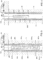
- Figure 3 shows an alternate example of a well treatment system 10A where the perforating string 18A is disposed in wellbore 12 and shown having additive castings 30A 1 -30A n disposed within the annular gun bodies 24A 1 -24A n .
- the additive castings 30A 1 -30A n are disk like members and placed adjacent the shaped charges 28A disposed within the gun bodies 24A 1 -24A n .
- the operational sequence of the embodiment of the well treatment system 10A of Figure 3 is much the same as that of the system 10 of Figure 1 , that is detonation of the shaped charges 24A 1 -24A n in turn causes initiation of a reaction of the additive castings 30A 1 -30A n , thereby releasing a treatment substance into the wellbore 12.
- initiation reaction of the energetic material can be employed, such as electricity ( i.e. via wireline 32) or from a detonation wave from detonation cord 29A in the perforating string 18A.
- FIG. 4 Another alternate example of a well treatment system 10B is shown in a side partial sectional view in Figure 4 .
- the additive casting 30B is an elongate cylindrical member disposed on an end of wireline 32 and set within wellbore 12.
- perforations 36 have already been formed within the formation 14.
- a signal from the surface truck 33 via wireline 32 makes it way to the additive casting 30B to initiate a reaction of the energetic material making up the casting 30B, and thereby releasing the treatment substance into the wellbore 12 and into perforations 36.
- an additive casting 30 the energetic material is bound to a settable material, combined with a wellbore treatment material, and then molded into a desired shape, such as the annular shape of the additive casting 30 of Figure 1 .
- Example settable materials include thermosetting polymers, resins, thermosetting resins, acrylic resins, polyesters, vinyl esters, epoxy, polyurethane, phenolic resins, amino resins, furan resins, any other material that is moldable and then hardens, and combinations thereof.
- An alternate embodiment of forming the casting 30 includes mixing a liquid-form resin with a powdered composition of crystalline acid and a propellant, and molding the mixture into a disk or other shape.
- the propellant/acid disk is then placed adjacent to conventional shaped charges within a perforating gun assembly.
- the propellant/acid combination is cast as a cylinder (casting 30B of Figure 4 ) and conveyed downhole to treat a previously perforated wellbore.
- reaction of the propellant is initiated by means other than a shaped charge, such as by a detonating cord or other suitable initiator.
- Other components, such as wellbore treatment materials, which include acids, anhydrous acids, crystalline acids, and anhydrous crystalline acids, are optionally blended into the mixture of the energetic material and resin.
- the gas generated by an oxidation process of the energetic material urges the acid into the perforations 36, and the energetic material is a conveyance or delivery method rather than a stimulation tool.
- the acid/energetic material composition is cast into tubes and placed inside perforation gun bodies 24 1 -24 n ( Figure 1 ).
- One example propellant for use in the casings described above includes potassium perchlorate.
- detonating a perforating gun generates extreme pressure and heat that ignite the propellant material.
- a high-velocity gas is generated which carries the crystalline acid into the perforations.
- the acid reconstitutes as a liquid acid that reacts with the crushed and compacted rock surrounding the perforation tunnels.
- the calcareous components of the crushed rock can be dissolved or the rock matrix itself can be removed.
- a significant advantage realized by the present disclosure is that costly equipment for pumping wellbore treatment fluids downhole is not required. Another advantage is that the amount of wellbore treatment fluids or material can be greatly reduced as well as an excessive amount of wellbore treatment fluid is consumed when being pumped downhole. Typical acidizing treatment operations require many hundreds of liters of acid, whereas implementation of the presently disclosed technique is expected to require only grams of treatment substance.
Landscapes
- Geology (AREA)
- Life Sciences & Earth Sciences (AREA)
- Engineering & Computer Science (AREA)
- Mining & Mineral Resources (AREA)
- Environmental & Geological Engineering (AREA)
- Fluid Mechanics (AREA)
- Physics & Mathematics (AREA)
- General Life Sciences & Earth Sciences (AREA)
- Geochemistry & Mineralogy (AREA)
- Drilling And Exploitation, And Mining Machines And Methods (AREA)
- Treating Waste Gases (AREA)
- Manufacturing Of Micro-Capsules (AREA)
- Liquid Deposition Of Substances Of Which Semiconductor Devices Are Composed (AREA)
Claims (15)
- Procédé d'opérations dans un puits de forage (12) comprenant :le déploiement d'un outil de fond de trou dans le puits de forage (12), l'outil de fond de trou comprenant un coulage additif (301-30n, 30A1-30An, 30B) qui comprend un matériau énergétique et un acide anhydre cristallin mélangés conjointement avec une résine ;le positionnement de l'outil de fond de trou au niveau d'une profondeur désignée dans le puits de forage (12) ; etle fait d'amener une réaction du matériau énergétique pour générer de l'énergie qui entraîne l'acide anhydre cristallin dans une ouverture formée dans une paroi latérale du puits de forage (12) ce qui augmente un écoulement d'hydrocarbures à travers l'ouverture.
- Procédé selon la revendication 1, dans lequel l'outil de fond de trou comprend en outre un explosif, et dans lequel l'étape consistant à amener une réaction du matériau énergétique comprend le déclenchement d'une détonation de l'explosif de sorte que des produits de détonation de l'explosif viennent en contact avec le matériau énergétique à une température pour déclencher une réaction du matériau énergétique.
- Procédé selon la revendication 1, dans lequel l'énergie provient d'un gaz en expansion produit par la réaction du matériau énergétique, et dans lequel le matériau énergétique est mis en réaction parallèlement à la formation de perforations (36) dans une paroi latérale du puits de forage (12), de sorte que la substance de traitement est forcée dans les perforations (36) par le gaz en expansion.
- Procédé selon la revendication 3, dans lequel l'outil de fond de trou comprend un canon de perforation, et dans lequel l'explosif comprend un explosif fort disposé dans une pluralité de charges profilées (28, 28A) qui sont placées radialement vers l'intérieur à partir du coulage additif, de sorte que lorsque les explosifs forts dans les charges profilées sont mis à feu, des produits de détonation sont générés à partir de la détonation de l'explosif fort lesquels viennent en contact avec le matériau énergétique à une température pour déclencher une réaction du matériau énergétique.
- Procédé selon la revendication 4, dans lequel la détonation des charges profilées (28, 28A) forme des perforations (36) dans une paroi latérale du puits de forage (12), dans lequel une pluralité d'ouvertures sont formées dans la paroi latérale du puits de forage (12), et dans lequel les perforations (36) définissent les ouvertures.
- Procédé selon la revendication 1, dans lequel le coulage additif est formé en un élément annulaire qui entoure une partie de l'outil.
- Procédé selon la revendication 1, dans lequel le coulage additif est formé en un élément plan et disposé à l'intérieur d'un corps de l'outil.
- Procédé selon la revendication 1, dans lequel l'acide dissout la roche à l'intérieur de l'ouverture.
- Procédé selon la revendication 1, dans lequel le matériau énergétique comprend un propulseur.
- Outil de fond de trou pour utilisation dans des opérations dans un puits de forage (12) comprenant :un logement ;un explosif dans le logement et qui est orienté, de sorte que lorsque l'explosif est mis à feu, des produits de détonation sont formés lesquels se déplacent le long d'un trajet désigné ; etun coulage additif (301-30n, 30A1-30An, 30B) qui est traversé par le trajet désigné, le coulage additif (301-30n, 30A1-30An, 30B) comprenant une matrice solide d'un matériau durcissable, d'un matériau énergétique et d'un acide anhydre cristallin intégré dans une résine de sorte que lorsqu'une réaction dans le matériau énergétique est déclenchée dans le puits de forage (12), l'acide anhydre cristallin est libéré dans le puits de forage (12).
- Outil de fond de trou selon la revendication 10, dans lequel le matériau de traitement de puits de forage comprend un acide cristallin anhydre qui est réactif avec de la roche qui est traversée par une perforation de fond de trou (36).
- Outil de fond de trou selon la revendication 10, dans lequel le matériau énergétique comprend une substance qui produit de l'énergie ou du gaz sous pression lorsqu'elle est mise en réaction et est choisie dans le groupe constitué d'un propulseur, d'un oxydant, de perchlorate d'ammonium, de perchlorate de potassium, et de combinaisons de ceux-ci.
- Outil de fond de trou selon la revendication 10, dans lequel le logement comprend un corps de canon de perforation, dans lequel l'explosif comprend un explosif fort au sein d'une charge profilée, et dans lequel la détonation de l'explosif fort forme des ouvertures dans une paroi latérale du puits de forage (12).
- Outil de fond de trou selon la revendication 13, dans lequel le coulage additif comprend un élément annulaire couplé au logement.
- Outil de fond de trou selon la revendication 10, comprenant en outre un contrôleur (35) en communication avec l'explosif.
Applications Claiming Priority (2)
| Application Number | Priority Date | Filing Date | Title |
|---|---|---|---|
| US201662296308P | 2016-02-17 | 2016-02-17 | |
| PCT/US2017/018357 WO2017143181A1 (fr) | 2016-02-17 | 2017-02-17 | Système de traitement de puits de forage |
Publications (3)
| Publication Number | Publication Date |
|---|---|
| EP3417143A1 EP3417143A1 (fr) | 2018-12-26 |
| EP3417143A4 EP3417143A4 (fr) | 2019-11-06 |
| EP3417143B1 true EP3417143B1 (fr) | 2021-08-18 |
Family
ID=59560249
Family Applications (1)
| Application Number | Title | Priority Date | Filing Date |
|---|---|---|---|
| EP17753921.0A Active EP3417143B1 (fr) | 2016-02-17 | 2017-02-17 | Système de traitement de puits de forage |
Country Status (5)
| Country | Link |
|---|---|
| US (1) | US20170234116A1 (fr) |
| EP (1) | EP3417143B1 (fr) |
| BR (1) | BR112018015899B1 (fr) |
| SA (1) | SA518392182B1 (fr) |
| WO (1) | WO2017143181A1 (fr) |
Families Citing this family (6)
| Publication number | Priority date | Publication date | Assignee | Title |
|---|---|---|---|---|
| US11629585B2 (en) | 2019-01-16 | 2023-04-18 | Hunting Titan, Inc. | Integrated coaxial perforating acidizing operation |
| WO2020197607A1 (fr) * | 2019-03-27 | 2020-10-01 | Halliburton Energy Services, Inc. | Amélioration de placement de fluide de traitement dans une formation souterraine |
| US20210404299A1 (en) * | 2019-06-20 | 2021-12-30 | Halliburton Energy Services, Inc. | Microencapsulated Acid with Perforation Strategies to Improve the Delivery and Treatment of Formations in Hydraulic Fracturing Applications |
| US11352859B2 (en) | 2019-09-16 | 2022-06-07 | Halliburton Energy Services, Inc. | Well production enhancement systems and methods to enhance well production |
| US11994009B2 (en) * | 2020-03-31 | 2024-05-28 | Saudi Arabian Oil Company | Non-explosive CO2-based perforation tool for oil and gas downhole operations |
| US11441407B2 (en) * | 2020-06-15 | 2022-09-13 | Saudi Arabian Oil Company | Sheath encapsulation to convey acid to formation fracture |
Family Cites Families (16)
| Publication number | Priority date | Publication date | Assignee | Title |
|---|---|---|---|---|
| US3270668A (en) * | 1964-12-29 | 1966-09-06 | Atlantic Res Corp | Well-treating apparatus |
| US4976318A (en) * | 1989-12-01 | 1990-12-11 | Mohaupt Henry H | Technique and apparatus for stimulating long intervals |
| US6082450A (en) * | 1996-09-09 | 2000-07-04 | Marathon Oil Company | Apparatus and method for stimulating a subterranean formation |
| US7287589B2 (en) * | 2000-03-02 | 2007-10-30 | Schlumberger Technology Corporation | Well treatment system and method |
| US6722434B2 (en) * | 2002-05-31 | 2004-04-20 | Halliburton Energy Services, Inc. | Methods of generating gas in well treating fluids |
| US7216708B1 (en) * | 2003-09-12 | 2007-05-15 | Bond Lesley O | Reactive stimulation of oil and gas wells |
| US7621332B2 (en) * | 2005-10-18 | 2009-11-24 | Owen Oil Tools Lp | Apparatus and method for perforating and fracturing a subterranean formation |
| US7909096B2 (en) * | 2007-03-02 | 2011-03-22 | Schlumberger Technology Corporation | Method and apparatus of reservoir stimulation while running casing |
| US7909115B2 (en) * | 2007-09-07 | 2011-03-22 | Schlumberger Technology Corporation | Method for perforating utilizing a shaped charge in acidizing operations |
| US8794335B2 (en) * | 2011-04-21 | 2014-08-05 | Halliburton Energy Services, Inc. | Method and apparatus for expendable tubing-conveyed perforating gun |
| US9695677B2 (en) * | 2011-09-02 | 2017-07-04 | Schlumberger Technology Corporation | Disappearing perforating gun system |
| US9133695B2 (en) * | 2011-09-03 | 2015-09-15 | Baker Hughes Incorporated | Degradable shaped charge and perforating gun system |
| CN104066924A (zh) * | 2012-01-18 | 2014-09-24 | 欧文石油工具有限合伙公司 | 用于提高井眼穿孔的系统和方法 |
| US9926755B2 (en) * | 2013-05-03 | 2018-03-27 | Schlumberger Technology Corporation | Substantially degradable perforating gun technique |
| US10273792B2 (en) * | 2013-07-15 | 2019-04-30 | Triad National Security, Llc | Multi-stage geologic fracturing |
| WO2016022111A1 (fr) * | 2014-08-06 | 2016-02-11 | Halliburton Energy Services, Inc. | Dispositif de perforation pouvant se dissoudre |
-
2017
- 2017-02-17 BR BR112018015899-2A patent/BR112018015899B1/pt not_active IP Right Cessation
- 2017-02-17 WO PCT/US2017/018357 patent/WO2017143181A1/fr not_active Ceased
- 2017-02-17 US US15/435,469 patent/US20170234116A1/en not_active Abandoned
- 2017-02-17 EP EP17753921.0A patent/EP3417143B1/fr active Active
-
2018
- 2018-08-09 SA SA518392182A patent/SA518392182B1/ar unknown
Non-Patent Citations (1)
| Title |
|---|
| None * |
Also Published As
| Publication number | Publication date |
|---|---|
| BR112018015899A2 (pt) | 2018-12-26 |
| WO2017143181A1 (fr) | 2017-08-24 |
| US20170234116A1 (en) | 2017-08-17 |
| BR112018015899B1 (pt) | 2022-11-08 |
| EP3417143A1 (fr) | 2018-12-26 |
| SA518392182B1 (ar) | 2022-04-21 |
| EP3417143A4 (fr) | 2019-11-06 |
Similar Documents
| Publication | Publication Date | Title |
|---|---|---|
| EP3417143B1 (fr) | Système de traitement de puits de forage | |
| US9062534B2 (en) | Perforating system comprising an energetic material | |
| US7044225B2 (en) | Shaped charge | |
| US7909115B2 (en) | Method for perforating utilizing a shaped charge in acidizing operations | |
| US9671201B2 (en) | Dissolvable material application in perforating | |
| CA2745384C (fr) | Procede pour l'amelioration d'activites d'injection et stimulation de la production de petrole et de gaz | |
| US9080432B2 (en) | Energetic material applications in shaped charges for perforation operations | |
| US4391337A (en) | High-velocity jet and propellant fracture device for gas and oil well production | |
| AU2012300262B2 (en) | Disappearing perforating gun system | |
| US11143007B2 (en) | Method and systems for perforating and fragmenting sediments using blasting material | |
| US7228906B2 (en) | Propellant ignition assembly and process | |
| CN101316980B (zh) | 用于射孔和压裂由井眼横断的地下地层的设备和方法 | |
| US8127832B1 (en) | Well stimulation using reaction agents outside the casing | |
| US5145013A (en) | Sand control with resin and explosive | |
| US9068441B2 (en) | Perforating stimulating bullet |
Legal Events
| Date | Code | Title | Description |
|---|---|---|---|
| STAA | Information on the status of an ep patent application or granted ep patent |
Free format text: STATUS: THE INTERNATIONAL PUBLICATION HAS BEEN MADE |
|
| PUAI | Public reference made under article 153(3) epc to a published international application that has entered the european phase |
Free format text: ORIGINAL CODE: 0009012 |
|
| STAA | Information on the status of an ep patent application or granted ep patent |
Free format text: STATUS: REQUEST FOR EXAMINATION WAS MADE |
|
| 17P | Request for examination filed |
Effective date: 20180914 |
|
| AK | Designated contracting states |
Kind code of ref document: A1 Designated state(s): AL AT BE BG CH CY CZ DE DK EE ES FI FR GB GR HR HU IE IS IT LI LT LU LV MC MK MT NL NO PL PT RO RS SE SI SK SM TR |
|
| AX | Request for extension of the european patent |
Extension state: BA ME |
|
| DAV | Request for validation of the european patent (deleted) | ||
| DAX | Request for extension of the european patent (deleted) | ||
| A4 | Supplementary search report drawn up and despatched |
Effective date: 20191008 |
|
| RIC1 | Information provided on ipc code assigned before grant |
Ipc: E21B 43/11 20060101AFI20191001BHEP Ipc: E21B 43/117 20060101ALI20191001BHEP Ipc: E21B 43/25 20060101ALI20191001BHEP Ipc: E21B 43/116 20060101ALI20191001BHEP |
|
| STAA | Information on the status of an ep patent application or granted ep patent |
Free format text: STATUS: EXAMINATION IS IN PROGRESS |
|
| 17Q | First examination report despatched |
Effective date: 20200728 |
|
| GRAP | Despatch of communication of intention to grant a patent |
Free format text: ORIGINAL CODE: EPIDOSNIGR1 |
|
| STAA | Information on the status of an ep patent application or granted ep patent |
Free format text: STATUS: GRANT OF PATENT IS INTENDED |
|
| INTG | Intention to grant announced |
Effective date: 20210315 |
|
| RAP3 | Party data changed (applicant data changed or rights of an application transferred) |
Owner name: BAKER HUGHES HOLDINGS LLC |
|
| GRAS | Grant fee paid |
Free format text: ORIGINAL CODE: EPIDOSNIGR3 |
|
| GRAA | (expected) grant |
Free format text: ORIGINAL CODE: 0009210 |
|
| STAA | Information on the status of an ep patent application or granted ep patent |
Free format text: STATUS: THE PATENT HAS BEEN GRANTED |
|
| AK | Designated contracting states |
Kind code of ref document: B1 Designated state(s): AL AT BE BG CH CY CZ DE DK EE ES FI FR GB GR HR HU IE IS IT LI LT LU LV MC MK MT NL NO PL PT RO RS SE SI SK SM TR |
|
| REG | Reference to a national code |
Ref country code: GB Ref legal event code: FG4D |
|
| REG | Reference to a national code |
Ref country code: CH Ref legal event code: EP |
|
| REG | Reference to a national code |
Ref country code: DE Ref legal event code: R096 Ref document number: 602017044309 Country of ref document: DE |
|
| REG | Reference to a national code |
Ref country code: IE Ref legal event code: FG4D Ref country code: AT Ref legal event code: REF Ref document number: 1421808 Country of ref document: AT Kind code of ref document: T Effective date: 20210915 |
|
| REG | Reference to a national code |
Ref country code: LT Ref legal event code: MG9D |
|
| REG | Reference to a national code |
Ref country code: NL Ref legal event code: MP Effective date: 20210818 |
|
| REG | Reference to a national code |
Ref country code: AT Ref legal event code: MK05 Ref document number: 1421808 Country of ref document: AT Kind code of ref document: T Effective date: 20210818 |
|
| REG | Reference to a national code |
Ref country code: NO Ref legal event code: T2 Effective date: 20210818 |
|
| PG25 | Lapsed in a contracting state [announced via postgrant information from national office to epo] |
Ref country code: ES Free format text: LAPSE BECAUSE OF FAILURE TO SUBMIT A TRANSLATION OF THE DESCRIPTION OR TO PAY THE FEE WITHIN THE PRESCRIBED TIME-LIMIT Effective date: 20210818 Ref country code: FI Free format text: LAPSE BECAUSE OF FAILURE TO SUBMIT A TRANSLATION OF THE DESCRIPTION OR TO PAY THE FEE WITHIN THE PRESCRIBED TIME-LIMIT Effective date: 20210818 Ref country code: PT Free format text: LAPSE BECAUSE OF FAILURE TO SUBMIT A TRANSLATION OF THE DESCRIPTION OR TO PAY THE FEE WITHIN THE PRESCRIBED TIME-LIMIT Effective date: 20211220 Ref country code: LT Free format text: LAPSE BECAUSE OF FAILURE TO SUBMIT A TRANSLATION OF THE DESCRIPTION OR TO PAY THE FEE WITHIN THE PRESCRIBED TIME-LIMIT Effective date: 20210818 Ref country code: BG Free format text: LAPSE BECAUSE OF FAILURE TO SUBMIT A TRANSLATION OF THE DESCRIPTION OR TO PAY THE FEE WITHIN THE PRESCRIBED TIME-LIMIT Effective date: 20211118 Ref country code: AT Free format text: LAPSE BECAUSE OF FAILURE TO SUBMIT A TRANSLATION OF THE DESCRIPTION OR TO PAY THE FEE WITHIN THE PRESCRIBED TIME-LIMIT Effective date: 20210818 Ref country code: RS Free format text: LAPSE BECAUSE OF FAILURE TO SUBMIT A TRANSLATION OF THE DESCRIPTION OR TO PAY THE FEE WITHIN THE PRESCRIBED TIME-LIMIT Effective date: 20210818 Ref country code: SE Free format text: LAPSE BECAUSE OF FAILURE TO SUBMIT A TRANSLATION OF THE DESCRIPTION OR TO PAY THE FEE WITHIN THE PRESCRIBED TIME-LIMIT Effective date: 20210818 Ref country code: HR Free format text: LAPSE BECAUSE OF FAILURE TO SUBMIT A TRANSLATION OF THE DESCRIPTION OR TO PAY THE FEE WITHIN THE PRESCRIBED TIME-LIMIT Effective date: 20210818 |
|
| PG25 | Lapsed in a contracting state [announced via postgrant information from national office to epo] |
Ref country code: PL Free format text: LAPSE BECAUSE OF FAILURE TO SUBMIT A TRANSLATION OF THE DESCRIPTION OR TO PAY THE FEE WITHIN THE PRESCRIBED TIME-LIMIT Effective date: 20210818 Ref country code: LV Free format text: LAPSE BECAUSE OF FAILURE TO SUBMIT A TRANSLATION OF THE DESCRIPTION OR TO PAY THE FEE WITHIN THE PRESCRIBED TIME-LIMIT Effective date: 20210818 Ref country code: GR Free format text: LAPSE BECAUSE OF FAILURE TO SUBMIT A TRANSLATION OF THE DESCRIPTION OR TO PAY THE FEE WITHIN THE PRESCRIBED TIME-LIMIT Effective date: 20211119 |
|
| PG25 | Lapsed in a contracting state [announced via postgrant information from national office to epo] |
Ref country code: NL Free format text: LAPSE BECAUSE OF FAILURE TO SUBMIT A TRANSLATION OF THE DESCRIPTION OR TO PAY THE FEE WITHIN THE PRESCRIBED TIME-LIMIT Effective date: 20210818 |
|
| PG25 | Lapsed in a contracting state [announced via postgrant information from national office to epo] |
Ref country code: DK Free format text: LAPSE BECAUSE OF FAILURE TO SUBMIT A TRANSLATION OF THE DESCRIPTION OR TO PAY THE FEE WITHIN THE PRESCRIBED TIME-LIMIT Effective date: 20210818 |
|
| PGFP | Annual fee paid to national office [announced via postgrant information from national office to epo] |
Ref country code: GB Payment date: 20220119 Year of fee payment: 6 |
|
| REG | Reference to a national code |
Ref country code: DE Ref legal event code: R097 Ref document number: 602017044309 Country of ref document: DE |
|
| PG25 | Lapsed in a contracting state [announced via postgrant information from national office to epo] |
Ref country code: SM Free format text: LAPSE BECAUSE OF FAILURE TO SUBMIT A TRANSLATION OF THE DESCRIPTION OR TO PAY THE FEE WITHIN THE PRESCRIBED TIME-LIMIT Effective date: 20210818 Ref country code: SK Free format text: LAPSE BECAUSE OF FAILURE TO SUBMIT A TRANSLATION OF THE DESCRIPTION OR TO PAY THE FEE WITHIN THE PRESCRIBED TIME-LIMIT Effective date: 20210818 Ref country code: RO Free format text: LAPSE BECAUSE OF FAILURE TO SUBMIT A TRANSLATION OF THE DESCRIPTION OR TO PAY THE FEE WITHIN THE PRESCRIBED TIME-LIMIT Effective date: 20210818 Ref country code: EE Free format text: LAPSE BECAUSE OF FAILURE TO SUBMIT A TRANSLATION OF THE DESCRIPTION OR TO PAY THE FEE WITHIN THE PRESCRIBED TIME-LIMIT Effective date: 20210818 Ref country code: CZ Free format text: LAPSE BECAUSE OF FAILURE TO SUBMIT A TRANSLATION OF THE DESCRIPTION OR TO PAY THE FEE WITHIN THE PRESCRIBED TIME-LIMIT Effective date: 20210818 Ref country code: AL Free format text: LAPSE BECAUSE OF FAILURE TO SUBMIT A TRANSLATION OF THE DESCRIPTION OR TO PAY THE FEE WITHIN THE PRESCRIBED TIME-LIMIT Effective date: 20210818 |
|
| PGFP | Annual fee paid to national office [announced via postgrant information from national office to epo] |
Ref country code: NO Payment date: 20220121 Year of fee payment: 6 |
|
| PLBE | No opposition filed within time limit |
Free format text: ORIGINAL CODE: 0009261 |
|
| STAA | Information on the status of an ep patent application or granted ep patent |
Free format text: STATUS: NO OPPOSITION FILED WITHIN TIME LIMIT |
|
| 26N | No opposition filed |
Effective date: 20220519 |
|
| PG25 | Lapsed in a contracting state [announced via postgrant information from national office to epo] |
Ref country code: IT Free format text: LAPSE BECAUSE OF FAILURE TO SUBMIT A TRANSLATION OF THE DESCRIPTION OR TO PAY THE FEE WITHIN THE PRESCRIBED TIME-LIMIT Effective date: 20210818 |
|
| PG25 | Lapsed in a contracting state [announced via postgrant information from national office to epo] |
Ref country code: SI Free format text: LAPSE BECAUSE OF FAILURE TO SUBMIT A TRANSLATION OF THE DESCRIPTION OR TO PAY THE FEE WITHIN THE PRESCRIBED TIME-LIMIT Effective date: 20210818 |
|
| REG | Reference to a national code |
Ref country code: DE Ref legal event code: R119 Ref document number: 602017044309 Country of ref document: DE |
|
| PG25 | Lapsed in a contracting state [announced via postgrant information from national office to epo] |
Ref country code: MC Free format text: LAPSE BECAUSE OF FAILURE TO SUBMIT A TRANSLATION OF THE DESCRIPTION OR TO PAY THE FEE WITHIN THE PRESCRIBED TIME-LIMIT Effective date: 20210818 |
|
| REG | Reference to a national code |
Ref country code: CH Ref legal event code: PL |
|
| REG | Reference to a national code |
Ref country code: BE Ref legal event code: MM Effective date: 20220228 |
|
| PG25 | Lapsed in a contracting state [announced via postgrant information from national office to epo] |
Ref country code: LU Free format text: LAPSE BECAUSE OF NON-PAYMENT OF DUE FEES Effective date: 20220217 |
|
| PG25 | Lapsed in a contracting state [announced via postgrant information from national office to epo] |
Ref country code: FR Free format text: LAPSE BECAUSE OF NON-PAYMENT OF DUE FEES Effective date: 20220228 |
|
| PG25 | Lapsed in a contracting state [announced via postgrant information from national office to epo] |
Ref country code: LI Free format text: LAPSE BECAUSE OF NON-PAYMENT OF DUE FEES Effective date: 20220228 Ref country code: IE Free format text: LAPSE BECAUSE OF NON-PAYMENT OF DUE FEES Effective date: 20220217 Ref country code: DE Free format text: LAPSE BECAUSE OF NON-PAYMENT OF DUE FEES Effective date: 20220901 Ref country code: CH Free format text: LAPSE BECAUSE OF NON-PAYMENT OF DUE FEES Effective date: 20220228 |
|
| PG25 | Lapsed in a contracting state [announced via postgrant information from national office to epo] |
Ref country code: BE Free format text: LAPSE BECAUSE OF NON-PAYMENT OF DUE FEES Effective date: 20220228 |
|
| REG | Reference to a national code |
Ref country code: NO Ref legal event code: MMEP |
|
| GBPC | Gb: european patent ceased through non-payment of renewal fee |
Effective date: 20230217 |
|
| PG25 | Lapsed in a contracting state [announced via postgrant information from national office to epo] |
Ref country code: NO Free format text: LAPSE BECAUSE OF NON-PAYMENT OF DUE FEES Effective date: 20230228 |
|
| PG25 | Lapsed in a contracting state [announced via postgrant information from national office to epo] |
Ref country code: GB Free format text: LAPSE BECAUSE OF NON-PAYMENT OF DUE FEES Effective date: 20230217 |
|
| PG25 | Lapsed in a contracting state [announced via postgrant information from national office to epo] |
Ref country code: GB Free format text: LAPSE BECAUSE OF NON-PAYMENT OF DUE FEES Effective date: 20230217 |
|
| PG25 | Lapsed in a contracting state [announced via postgrant information from national office to epo] |
Ref country code: HU Free format text: LAPSE BECAUSE OF FAILURE TO SUBMIT A TRANSLATION OF THE DESCRIPTION OR TO PAY THE FEE WITHIN THE PRESCRIBED TIME-LIMIT; INVALID AB INITIO Effective date: 20170217 |
|
| PG25 | Lapsed in a contracting state [announced via postgrant information from national office to epo] |
Ref country code: MK Free format text: LAPSE BECAUSE OF FAILURE TO SUBMIT A TRANSLATION OF THE DESCRIPTION OR TO PAY THE FEE WITHIN THE PRESCRIBED TIME-LIMIT Effective date: 20210818 Ref country code: CY Free format text: LAPSE BECAUSE OF FAILURE TO SUBMIT A TRANSLATION OF THE DESCRIPTION OR TO PAY THE FEE WITHIN THE PRESCRIBED TIME-LIMIT Effective date: 20210818 |
|
| PG25 | Lapsed in a contracting state [announced via postgrant information from national office to epo] |
Ref country code: MT Free format text: LAPSE BECAUSE OF FAILURE TO SUBMIT A TRANSLATION OF THE DESCRIPTION OR TO PAY THE FEE WITHIN THE PRESCRIBED TIME-LIMIT Effective date: 20210818 |
|
| PG25 | Lapsed in a contracting state [announced via postgrant information from national office to epo] |
Ref country code: TR Free format text: LAPSE BECAUSE OF FAILURE TO SUBMIT A TRANSLATION OF THE DESCRIPTION OR TO PAY THE FEE WITHIN THE PRESCRIBED TIME-LIMIT Effective date: 20210818 |