EP3417146B1 - Procédé et appareil pour estimer des propriétés de formations en utilisant des mesures électromagnétiques transitoires pendant le forage - Google Patents
Procédé et appareil pour estimer des propriétés de formations en utilisant des mesures électromagnétiques transitoires pendant le forage Download PDFInfo
- Publication number
- EP3417146B1 EP3417146B1 EP17753738.8A EP17753738A EP3417146B1 EP 3417146 B1 EP3417146 B1 EP 3417146B1 EP 17753738 A EP17753738 A EP 17753738A EP 3417146 B1 EP3417146 B1 EP 3417146B1
- Authority
- EP
- European Patent Office
- Prior art keywords
- signal
- formation
- carrier
- synthetic
- receiver
- Prior art date
- Legal status (The legal status is an assumption and is not a legal conclusion. Google has not performed a legal analysis and makes no representation as to the accuracy of the status listed.)
- Active
Links
Images




Classifications
-
- G—PHYSICS
- G01—MEASURING; TESTING
- G01V—GEOPHYSICS; GRAVITATIONAL MEASUREMENTS; DETECTING MASSES OR OBJECTS; TAGS
- G01V3/00—Electric or magnetic prospecting or detecting; Measuring magnetic field characteristics of the earth, e.g. declination, deviation
- G01V3/18—Electric or magnetic prospecting or detecting; Measuring magnetic field characteristics of the earth, e.g. declination, deviation specially adapted for well-logging
- G01V3/26—Electric or magnetic prospecting or detecting; Measuring magnetic field characteristics of the earth, e.g. declination, deviation specially adapted for well-logging operating with magnetic or electric fields produced or modified either by the surrounding earth formation or by the detecting device
- G01V3/28—Electric or magnetic prospecting or detecting; Measuring magnetic field characteristics of the earth, e.g. declination, deviation specially adapted for well-logging operating with magnetic or electric fields produced or modified either by the surrounding earth formation or by the detecting device using induction coils
-
- E—FIXED CONSTRUCTIONS
- E21—EARTH OR ROCK DRILLING; MINING
- E21B—EARTH OR ROCK DRILLING; OBTAINING OIL, GAS, WATER, SOLUBLE OR MELTABLE MATERIALS OR A SLURRY OF MINERALS FROM WELLS
- E21B44/00—Automatic control systems specially adapted for drilling operations, i.e. self-operating systems which function to carry out or modify a drilling operation without intervention of a human operator, e.g. computer-controlled drilling systems; Systems specially adapted for monitoring a plurality of drilling variables or conditions
-
- E—FIXED CONSTRUCTIONS
- E21—EARTH OR ROCK DRILLING; MINING
- E21B—EARTH OR ROCK DRILLING; OBTAINING OIL, GAS, WATER, SOLUBLE OR MELTABLE MATERIALS OR A SLURRY OF MINERALS FROM WELLS
- E21B47/00—Survey of boreholes or wells
- E21B47/12—Means for transmitting measuring-signals or control signals from the well to the surface, or from the surface to the well, e.g. for logging while drilling
- E21B47/13—Means for transmitting measuring-signals or control signals from the well to the surface, or from the surface to the well, e.g. for logging while drilling by electromagnetic energy, e.g. radio frequency
-
- E—FIXED CONSTRUCTIONS
- E21—EARTH OR ROCK DRILLING; MINING
- E21B—EARTH OR ROCK DRILLING; OBTAINING OIL, GAS, WATER, SOLUBLE OR MELTABLE MATERIALS OR A SLURRY OF MINERALS FROM WELLS
- E21B49/00—Testing the nature of borehole walls; Formation testing; Methods or apparatus for obtaining samples of soil or well fluids, specially adapted to earth drilling or wells
-
- E—FIXED CONSTRUCTIONS
- E21—EARTH OR ROCK DRILLING; MINING
- E21B—EARTH OR ROCK DRILLING; OBTAINING OIL, GAS, WATER, SOLUBLE OR MELTABLE MATERIALS OR A SLURRY OF MINERALS FROM WELLS
- E21B7/00—Special methods or apparatus for drilling
- E21B7/04—Directional drilling
-
- G—PHYSICS
- G01—MEASURING; TESTING
- G01V—GEOPHYSICS; GRAVITATIONAL MEASUREMENTS; DETECTING MASSES OR OBJECTS; TAGS
- G01V3/00—Electric or magnetic prospecting or detecting; Measuring magnetic field characteristics of the earth, e.g. declination, deviation
- G01V3/18—Electric or magnetic prospecting or detecting; Measuring magnetic field characteristics of the earth, e.g. declination, deviation specially adapted for well-logging
-
- G—PHYSICS
- G01—MEASURING; TESTING
- G01V—GEOPHYSICS; GRAVITATIONAL MEASUREMENTS; DETECTING MASSES OR OBJECTS; TAGS
- G01V3/00—Electric or magnetic prospecting or detecting; Measuring magnetic field characteristics of the earth, e.g. declination, deviation
- G01V3/18—Electric or magnetic prospecting or detecting; Measuring magnetic field characteristics of the earth, e.g. declination, deviation specially adapted for well-logging
- G01V3/26—Electric or magnetic prospecting or detecting; Measuring magnetic field characteristics of the earth, e.g. declination, deviation specially adapted for well-logging operating with magnetic or electric fields produced or modified either by the surrounding earth formation or by the detecting device
-
- G—PHYSICS
- G01—MEASURING; TESTING
- G01V—GEOPHYSICS; GRAVITATIONAL MEASUREMENTS; DETECTING MASSES OR OBJECTS; TAGS
- G01V3/00—Electric or magnetic prospecting or detecting; Measuring magnetic field characteristics of the earth, e.g. declination, deviation
- G01V3/38—Processing data, e.g. for analysis, for interpretation, for correction
Definitions
- Inversion requires a mathematical model, which is used to produce synthetic data.
- the model has to include all of the necessary parameters that affect the measurements because an accurate model is needed for a successful inversion. Because the amount of recordable data is limited, no geophysical inverse problem is uniquely solvable and inferences of formation properties are statistical.
- the possibility to reduce the range of uncertainty in the inverted models is driven by the sensitivity of the data to parameters of interest and a level of noise in the data.
- the noise can be either random or systematic.
- mechanisms for improving sensitivity to the parameters of a formation have been developed.
- a technique referred to as bucking was developed to improve sensitivity to the parameters of the formation while eliminating systematic noise caused by a primary field and/or the conductive tools used to make the measurements. If bucking does not account for electromagnetic interference between a conductive tool body and a formation, this interference will create or be a source of additional systematic noise. For this reason, it is beneficial to develop techniques for reducing inconsistency between measured and synthetic model responses and thus reduce uncertainty in estimated parameters of a formation.
- US2014121974A1 discloses an apparatus and method for deep transient resistivity measurements.
- US2011257886A1 discloses a three-coil system with short nonconductive inserts for transient MWD resistivity measurements.
- US2010097065A1 discloses a method and apparatus for while-drilling transient resistivity measurements.
- a method for estimating a property of an earth formation penetrated by a borehole is provided in accordance with claim 1.
- the signal is the subject of inversion, aimed at finding parameters of a model providing a best match between measured and synthetic data.
- the synthetic data or response is generated using approximate forward modeling solution, obtained via Duhamel's integral applied to formation signals in the absence of the pipe and, in some embodiments, a system step response estimated in the presence of the pipe in the air.
- FIG. 1 a non-limiting schematic illustration of a downhole drilling, monitoring, evaluation, exploration, and/or production system 100 associated with a borehole 102 is shown.
- a carrier 104 is run in the borehole 102, which penetrates one or more earth formations 106a, 106b for facilitating operations such as drilling, extracting matter from the formation, sequestering fluids such as carbon dioxide, and/or making measurements of properties of the formations 106a, 106b, a formation interface 107 (i.e., the interface between the formations 106a, 106b), and/or the borehole 102 downhole.
- the carrier 104 includes any of various components to facilitate subterranean operations.
- the carrier 104 is constructed of, for example, a pipe, multiple pipe sections, flexible tubing, or other structures. In other configurations, the carrier 104 is constructed of an armored wireline, such as that used in wireline logging.
- the carrier 104 is configured to include, for example, a drilling system and/or a bottom-hole assembly (BHA) on a downhole end thereof.
- BHA bottom-hole assembly
- the system 100 and/or the carrier 104 may include any number of downhole tools 108 for various processes including drilling, hydrocarbon production, and formation evaluation for measuring one or more physical properties, characteristics, quantities, etc. in and/or around the borehole 102.
- the downhole tools 108 include a drilling assembly and/or a pumping assembly.
- Various measurement tools can be incorporated into the system 100 to affect measurement regimes such as wireline measurement applications, measurement-while-drilling (MWD), and/or logging-while-drilling (LWD) applications.
- FIG. 1 shows the downhole tools 108 disposed in the borehole 102 penetrating the earth 109 (including a first formation 106a and a second formation 106b).
- the downhole tools 108 are disposed in the borehole 102 at a distal end of the carrier 104.
- the downhole tools 108 include measurement tools 110 and downhole electronics 112 configured to perform one or more types of measurements in LWD or MWD applications and/or operations.
- the carrier 104 is a drill string.
- the measurements may include measurements related to drill string operation, for example.
- a drilling rig 114 is configured to conduct drilling operations such as rotating the carrier 104 (e.g., a drill string) and, thus, a drill bit 116 located on the distal end of the carrier 104. As shown, the drilling rig 114 is configured to pump drilling fluid 118a through the carrier 104 in order to lubricate the drill bit 116. The drilling fluid 118a becomes a flushing fluid 118b to flush cuttings from the borehole 102.
- the downhole electronics 112 are configured generate data, i.e., collect data, at the downhole tools 108.
- Raw data and/or information processed by the downhole electronics 112 may be telemetered along telemetry 113 to the surface for additional processing or display by a computing system 120.
- drilling control signals are generated by the computing system 120 and conveyed downhole the downhole tools 108 or, in alternative configurations, are generated within the downhole electronics 112 or by a combination thereof.
- the downhole electronics 112 and the computing system 120 may each include one or more processors and one or more memory devices.
- Different layers or formations of the earth 109 may each have a unique resistivity.
- the first formation 106a may have a first resistivity and the second formation 106b may have a second resistivity.
- the first resistivity may be different from the second resistivity.
- the downhole tools 108 are configured to obtain electromagnetic information.
- the downhole tools 108 include one or more transmitters (transmitter coils) that turn a current impulse in a transmitter coil on and off to induce a current in the earth 109 (e.g., formations 106a, 106b).
- transmitters transmitter coils
- receivers are be configured to receive a resulting transient electromagnetic (TEM) signal.
- TEM transient electromagnetic
- the transmitter(s) and receiver(s) may be one-, two-, or tri-axis devices, and/or other transceiver devices may be employed without departing from the scope of the present disclosure.
- the transmitters may use magnetic dipoles to induce currents in the earth 109.
- FIG. 2 a schematic illustration of a transient electromagnetic method of downhole geophysical measurement is shown.
- a formation 206 is shown having a borehole 202 formed therein.
- Components of a downhole tool are schematically shown as a transmitter 222 and a receiver 224.
- the transmitter 222 is configured to employ a fast reversing magnetic dipole, denoted as primary magnetic field B1 to induce currents in the formation 206. These currents diffuse outward away from the borehole 202, as schematically illustrated.
- the currents within the formation generate a secondary magnetic field B2.
- a derivative of the secondary magnetic field B2 is sensed by the receiver 224.
- a measurement obtained by the downhole tool e.g., receiver 224
- a measurement obtained by the downhole tool e.g., receiver 224
- Inversion of geophysical data e.g., the measured magnetic field at the receiver 2244
- the inferences involve a process of finding model that provides a best-fit between the measurements and synthetic data, wherein the synthetic data is data configured to remove known uncertainties.
- the fast reversing magnetic dipole of the transmitter 222 may induce eddy currents in the carrier that supports and carries the downhole tools including the transmitter 222 and the received 224 (e.g., as shown in FIG. 1 ), which results in uncertainty in the model fitting.
- the carrier e.g., a drill string
- uncertainty in signals can arise.
- a drill collar is configured to carry a transient electromagnetic apparatus (e.g., the electromagnetic apparatus includes the transmitter 222 and the receiver 224).
- FIG. 3 an illustration of the interaction of transmitted magnetic field and magnetic field from currents induced in the carrier 304 during a transient measurement are shown.
- a transmitter (not shown) is oriented in the axial direction, designated as a Z direction.
- a receiver 324 is configured as a cylindrical magnetically permeable core mounted in a recess of the carrier 304, such as a conductive metallic mandrel 326 of a downhole tool.
- the transmitter located a predetermined distance away in the Z direction, may produce a step Bz in magnetic field along the axis of the receiver 324 (e.g., along the Z direction of the receiver 324).
- the magnetic core of the receiver 324 shields the carrier 304 from the step Bz in magnetic field, but at the edges of the magnetic core of the receiver 324 a circumferential current Ic may be induced in the metallic mandrel 326 of the carrier 304.
- the induced circumferential current Ic will produce a magnetic field Bc that opposes the transmitter induced step Bz in magnetic field.
- a summation of the transmitter magnetic field (e.g., Bz) and carrier current induced magnetic field (e.g., Bc) to produce the total axial magnetic field in the vicinity of the receiver 324 is a measured magnetic field, and thus modified from an actual induced current from a formation.
- the total magnetic field e.g., measurement
- a total sum and a secondary field that is induced by the sum in the formation can be measured.
- This additional magnetic field can result in measurements that deviate from a desired measurement. That is, the additional magnetic field alters measured results and thus impact models that are desired to determine a structure, composition, and/or other characteristic of one or more formations in the earth.
- the cumulative effect of the carrier signal causes modeling to diverge significantly from a data-set (e.g., measurements) that were based solely on signals measured without the influence and/or impact of a magnetic field in a carrier. That is, while the magnetic field from carrier currents affects a formation response, it may also dominate a signal measured in the receiver, effectively masking a formation response during the measurement.
- FIG. 4 a schematic illustration of a carrier 404 configured to account for a carrier induced signal is shown.
- the carrier 404 is configured to perform an operation referred to as bucking, wherein a carrier induced signal is detected and then removed from a total signal to thus extract out a formation signal.
- the carrier 404 is configured with a bit 416 disposed on a distal end of the carrier 404.
- a transmitter 422 is located on the carrier 404 and a first, or main, receiver 424a is located on the carrier 404 at a first distance D1 from the transmitter 422.
- a second, or bucking, receiver 424b is located on the carrier 404 at a second distance D2 from the transmitter 422.
- the carrier induced signal is suppressed by using the two receivers 424a, 424b which are spaced apart by a third distance D3 (i.e., the difference between distances D1 and D2).
- the signal induced in the receivers 424a, 424b by carrier currents is proportional to the cube of the distance between the specific receiver 424a, 424b and the transmitter 422, while a formation signal is almost equal in each receiver 424a, 424b.
- the bucking receiver (second receiver 424b) is shown as closer to the transmitter 422 than the main receiver (first receiver 424a). This configuration is merely provided for illustrative purposes and is not intended to be limiting.
- the bucking process is used to reduce uncertainty in measured data.
- synthetic data may be used to reduce the uncertainty of measurements, thus enabling better modeling and/or fits to models.
- the synthetic data is data that represents certain characteristics or components of a signal which are then accounted for in processing of measured real-world data, such that the output is an accurate reflection of the characteristics, features, and/or properties of the formation located in the earth. For example, if real-world data (e.g., measurements) are affected by a conductivity of a carrier in a downhole operation, the synthetic data have to be affected by the carrier as well.
- approximated modeling for a fast calculation of synthetic signal from the formation in the presence of a conductive carrier is provided.
- a derivation of a synthetic response used in inversion utilizes both Duhamel's integral and bucking (as described above).
- the synthetic data are calculated via Duhamel's integral by using a formation signal in the absence of the carrier and a system step response, which takes into account characteristics of a transmitter, one or more receivers, geometry and electrical properties of the carrier, etc.
- the system step response is defined as a signal measured in a receiver in a relatively resistive environment (e.g., in the air), when the transmitter is excited by a u(t)-step function.
- a derivation of a synthetic response takes into account a carrier-formation interaction and maintains a high sensitivity to parameters of formation.
- the derived synthetic response is further utilized to ensure reliable properties of formation from inversion.
- a formation has a resistivity associated therewith.
- the resistivity of the formation enables measurements of magnetic fields such that data may be generated that are representative of the formation. This data is then used to find a best-fit model, and thus an estimation of the physical characteristics and/or make-up of the formation may be made.
- a carrier particularly a metallic carrier, introduces uncertainty when fitting a model to the data.
- One source of such uncertainty is a magnetic field induced by the carrier itself, as described above, and is accounted for by a bucking process.
- Embodiments provided herein supply a solution that takes advantage of a significant difference in resistivity between a highly conductive carrier (e.g., a steel pipe; approximately 10-6 ⁇ ) and relatively a resistive earth formation (e.g., greater than 1 ⁇ ).
- the transmitter being mounted on the carrier, generates strong eddy currents on a surface of the carrier (e.g., the mandrels of the carrier; see FIG. 3 ).
- the corresponding electromagnetic field from the carrier dominates over the signal caused by the formation.
- the decay of the transient process is mainly driven by the slowly decaying eddy currents on the carrier. These currents act as a secondary source with respect to the formation.
- the receivers, mounted on the carrier, will then measure a total signal caused by both eddy currents on the carrier and in the formation.
- a model in accordance with the present disclosure, is comprised of an arbitrary formation surrounding a transient transmitter-receiver system mounted on a conductive carrier.
- the transmitter represents a coil with a current, whose magnetic moment can be turned on and off.
- b'(t) is a system step response, which represents db dt in a receiver in the presence of the carrier.
- the current in the transmitter has shape of step-function u(t) and measurements are taken in the absence of formation (in the air);
- f(t) is a formation response, which represents a signal in the receiver excited by the transmitter in the absence of the carrier.
- the current in the transmitter has shape of step-function u(t).
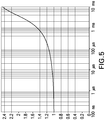
- the vertical axis is a normalized step system response b b 0
- the horizontal axis is time.
- the magnetic field b(t) is normalized by a value of the magnetic field b 0 measured immediately after turning off current in the transmitter.
- the magnetic field in the receiver is not a constant, but rather varies with time, both for the main and bucking receivers (shown as substantially overlapping in FIG. 5 ).
- a constant magnetic field would correspond to an ideally conductive carrier. In case of a material like steel for a carrier, having a finite conductivity, the eddy currents start penetrating through the carrier and this causes deviation of the magnetic field in the receiver from the constant.
- the variable in time magnetic field produces eddy currents in the formation, which in turn, induce a signal in the receiver.
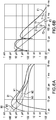
- FIGS. 6A-6F are plots of signals received at one or more receivers (voltage (vertical axis) as a function of time (horizontal axis)).
- Various of FIGS. 6A-6F include plots of a signal at a main receiver and a signal at a bucking receiver. Further, the plots include signals in the main and bucking receivers in the presence of a conductive carrier surrounded by a homogeneous formation of 1 ⁇ -m, 10 ⁇ -m, and 100 ⁇ -m.
- main receiver-1 ⁇ -m will be labeled M1; main receiver-10 ⁇ -m will be labeled M2; main receiver-100 ⁇ -m will be labeled M3; bucking receiver-1 ⁇ -m will be labeled B1; bucking receiver-10 ⁇ -m will be labeled B2; bucking receiver-100 ⁇ -m will be labeled B3.
- FIG. 6A shows a plot of simulated signals in a main receiver (S main (t)) and a bucking receiver (S bucking (t)) in the presence of a conductive carrier surrounded by homogeneous formations of 1 ⁇ -m (lines M1, B1), 10 ⁇ -m (lines M2, B2), and 100 ⁇ -m (lines M3, B3).
- the vertical axis is the voltage of the signal and the horizontal axis is the time.
- a bucked signal of a 1 ⁇ -m formation is labeled F1; a bucked signal of a 10 ⁇ -m formation is labeled F2; a bucked signal of a 100 ⁇ -m formation is labeled F3.
- the vertical axis is the voltage of the bucked signal ⁇ S and the horizontal axis is time.
- the time moment used to calculate the bucking coefficient k is mainly driven by a thickness ⁇ and a resistivity ⁇ of the carrier.
- the estimate for t 0 is about 800 ⁇ s.
- the bucked signals of FIG. 6B were derived from the simulated signals of FIG. 6A as they deviate from an ideal dipole response.
- the ideal dipole responses for the associated formations are shown as lines I1, I2, and I3.
- the ideal dipole response is a response or signal that would be measured or detected if no carrier was present.
- 11 is an ideal dipole response for a homogeneous formation of 1 ⁇ -m
- 12 is an ideal dipole response for a homogeneous formation of 10 ⁇ -m
- 13 is an ideal dipole response for a homogeneous formation of 100 ⁇ -m.
- As shown in FIG. 6B as the resistivity of the formation increases, so does the deviation.
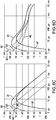
- calculated signals (f(t)) in homogeneous formations of 1 ⁇ -m (lines M1, B1), 10 ⁇ -m (lines M2, B2), and 100 ⁇ -m (lines M3, B3) in the absence of a carrier are shown.
- the vertical axis is the voltage of the receiver signal in the absence of a carrier and the horizontal axis is time.
- Duhamel's integral (Eq. (1)) is applied to f(t) and b (t) to derive a synthetic unbucked signals in the main receiver S main con t and the bucking receiver S bucking con t . That is, convolved signals are generated for both main and bucking receivers, and for each homogeneous formation.
- the derived/convolved signals for the different formations are presented in FIG. 6D .
- the vertical axis is a voltage of a convolved receiver signal and the horizontal axis is time.
- a synthetic bucked formation signal ⁇ S con of a 1 ⁇ -m formation is labeled C1; a synthetic buck formation signal ⁇ S con of a 10 ⁇ -m formation is labeled C2; a synthetic bucked formation signal ⁇ S con of a 100 ⁇ -m formation is labeled C3.
- the vertical axis is the voltage of the synthetic bucked formation signal ⁇ S con and the horizontal axis is time.
- the vertical axis is the voltage of the bucked signals and the synthetic bucked signals and the horizontal axis is time.
- the synthetic bucked signals ( ⁇ S con ) coincide with the bucked signals ( ⁇ S) in the time range up to 200 ⁇ s. Further, for formations with resistivity 10 ⁇ -m and below, the overlap is observed in the time intervals above 200 ⁇ s.
- FIG. 7 a flow process 700 in accordance with an embodiment of the present disclosure is shown.
- the flow process 700 may be employed in a system similar to that shown in FIG. 1 , although other configurations are contemplated and may take advantage of embodiments provided herein.
- the flow process 700, or portions thereof, may be used in application at or near a borehole through which a carrier will be conveyed and formation properties are to be estimated.
- a first transient electromagnetic field is generated by a transmitter on a carrier.
- the first transient electromagnetic field is generated when the carrier is not within the borehole. That is, the first transient electromagnetic field is generated by the transmitter when the field would not be affected by the formation.
- any detected or received signal due to the first transient electromagnetic field would be a result of a conductivity of the carrier, and not affected by a conductivity of a formation.
- a transmitting current to generate the first transient electromagnetic field in the carrier may have a shape of a step function u(t).
- a first receiver on the carrier receives a first measured signal due to the first transient electromagnetic field.
- the first measured signal is a signal received at the first receiver along the carrier when the carrier is not within a borehole, and thus the first measured signal is not affected by a formation.
- the first measured signal in some embodiments, is represented as S main (t) taken in the absence of a formation.
- a second receiver on the carrier receives a second measured signal due to the first transient electromagnetic field. Similar to the first measured signal, the second measured signal is a signal received at the second receiver along the carrier when the carrier is not within a borehole, and thus the second measured signal is not affected by a formation.
- the second measured signal in some embodiments, is represented as S bucking (t) taken in the absence of a formation.
- a bucking coefficient k is calculated.
- the bucking coefficient is calculated from the measurements of the first transient magnetic field (in some embodiments including a system step response) by first (e.g., main) and second (e.g., bucking) receivers on a carrier taken in the absence of a formation, e.g., when surrounded by air or no formation is present.
- the estimation of the coefficient k is based on a time window [t min , t max ] centered with respect to a time t 0 ⁇ ⁇ 0 ⁇ 2 2 ⁇ .
- the carrier is conveyed into the borehole, as shown at block 710.
- a second transient electromagnetic field is generated from the transmitter on the carrier.
- the resulting signals will be impacted by the presence of the formation that is downhole, and is a formation of interest for estimating a property thereof.
- the first receiver receives a third measured signal.
- the third measured signal is a signal that is due to the second transient electromagnetic field with the carrier downhole, and thus affected by the formation.
- this is a measured signal at the first (or main) receiver, this may be represented as b 1 '(t) or S main (t) taken in the presence of a formation.
- the second receiver receives a fourth measured signal.
- the fourth measured signal is a signal that is due to the second transient electromagnetic field with the carrier downhole, and thus affected by the formation.
- this is a measured signal at the second (or bucking) receiver, this may be represented as b 2 '(t) or S bucking (t) taken in the presence of a formation.
- a bucked signal is calculated.
- the bucked signal is calculated using the calculated bucking coefficient k, the third measured signal, and the fourth measured signal.
- a first synthetic formation signal f 1 (t) is calculated, wherein f(t) is a formation response, which represents a signal in the receiver excited by the transmitter in the absence of the carrier.
- the first synthetic formation signal is a simulated or otherwise calculated signal that would be received by the first receiver in the presence of a formation, but in the absence of the carrier. That is, the first synthetic signal is a signal representing a signal that would exist if the second transient electromagnetic field was only affected by the formation (and not affected by the presence of the carrier) when the transmitter and first receiver (e.g., the carrier) was disposed downhole.
- a second synthetic formation signal f 2 (t) is calculated, wherein f(t) is a formation response, which represents a signal in the receiver excited by the transmitter in the absence of the carrier.
- the second synthetic formation signal is a simulated or otherwise calculated signal that would be received by the second receiver in the presence of a formation, but in the absence of the carrier. That is, the second synthetic signal is a signal representing a signal that would exist if the second transient electromagnetic field was only affected by the formation (and not affected by the presence of the carrier) when the transmitter and second receiver (e.g., the carrier) was disposed downhole.
- a third synthetic formation signal is calculated.
- a fourth synthetic formation signal is calculated.
- a synthetic bucked signal is calculated.
- an inversion with respect to a formation model is performed to extract and/or model properties of the formation, and thus adjust geo-steering of the carrier.
- the inversion includes a process of matching measured data to the model.
- the least square norm is used to characterize the goodness of matching. The measurements are well matched by the model if they deviate from the corresponding synthetic data not more than one standard deviation of noise.
- a best-fit model is be selected from the inversion, and thus properties of the formation may be determined and geo-steering may be adjusted appropriately based on the selected model (and thus the features, characteristics, and/or properties of the formation).
- the extracted property is a resistivity of an earth formation such that an operator may make informed decisions regarding geo-steering. Accordingly, embodiments provided herein may improve downhole operations, including but not limited to, improving efficiencies in measurement-while-drilling operations.
- a method and/or process for determining a resistivity property of an earth formation includes producing a transient electromagnetic signal using a transmitter on a carrier in the presence of air (e.g., without a formation present) and using at least two receivers on the carrier for producing an output signal unaffected by the formation.
- the output signal is be affected by a finite, non-zero conductivity of the carrier; and using a processor for calculating a bucking coefficient k.
- the carrier (and the transmitter/receivers) is conveyed in a borehole and produces an output signal affected by the formation.
- the output formation signal is affected by the finite, non-zero conductivity of the carrier.
- a bucked transient signal is calculated using borehole measurements and the bucking coefficient. Further, a synthetic signal using an initial model is generated, using Duhamel's integral applied to signals of formation signals in the absence of the carrier and a system step response.
- the initial model includes a formation property and the bucking coefficient. An inversion is performed to match the bucked measured signal and the bucked synthetic signal.
- various embodiments provided herein may provide improved and/or efficient processes for estimating a formation property. Such efficient and improved estimation may be made in improved timeframes, thus enabling an operator to make informed decisions regarding drilling and/or other downhole operations, and make adjustments thereto, as needed. Further advantages of various embodiments may include providing a very fast and accurate estimation of formation properties as compared to prior processes for making similar estimations.
- various analysis components may be used including a digital and/or an analog system.
- controllers, computer processing systems, and/or geo-steering systems as provided herein and/or used with embodiments described herein may include digital and/or analog systems.
- the systems may have components such as processors, storage media, memory, inputs, outputs, communications links (e.g., wired, wireless, optical, or other), user interfaces, software programs, signal processors (e.g., digital or analog) and other such components (e.g., such as resistors, capacitors, inductors, and others) to provide for operation and analyses of the apparatus and methods disclosed herein in any of several manners well-appreciated in the art.
- teachings may be, but need not be, implemented in conjunction with a set of computer executable instructions stored on a non-transitory computer readable medium, including memory (e.g., ROMs, RAMs), optical (e.g., CD-ROMs), or magnetic (e.g., disks, hard drives), or any other type that when executed causes a computer to implement the methods and/or processes described herein.
- ROMs read-only memory
- RAMs random access memory
- optical e.g., CD-ROMs
- magnetic e.g., disks, hard drives
- Processed data such as a result of an implemented method, may be transmitted as a signal via a processor output interface to a signal receiving device.
- the signal receiving device may be a display monitor or printer for presenting the result to a user.
- the signal receiving device may be memory or a storage medium. It will be appreciated that storing the result in memory or the storage medium may transform the memory or storage medium into a new state (i.e., containing the result) from a prior state (i.e., not containing the result). Further, in some embodiments, an alert signal may be transmitted from the processor to a user interface if the result exceeds a threshold value.
- a sensor, transmitter, receiver, transceiver, antenna, controller, optical unit, electrical unit, and/or electromechanical unit may be included in support of the various aspects discussed herein or in support of other functions beyond this disclosure.
Landscapes
- Life Sciences & Earth Sciences (AREA)
- Engineering & Computer Science (AREA)
- Physics & Mathematics (AREA)
- Geology (AREA)
- Remote Sensing (AREA)
- General Life Sciences & Earth Sciences (AREA)
- Environmental & Geological Engineering (AREA)
- Mining & Mineral Resources (AREA)
- Geophysics (AREA)
- General Physics & Mathematics (AREA)
- Fluid Mechanics (AREA)
- Geochemistry & Mineralogy (AREA)
- Electromagnetism (AREA)
- Geophysics And Detection Of Objects (AREA)
Claims (13)
- Procédé d'estimation d'une propriété d'une formation terrestre (106a, 106b, 206) pénétrée par un trou de forage (102, 202), le procédé comprenant :la génération d'un premier champ électromagnétique transitoire avec un émetteur (222, 422) sur un support (104, 304, 404) situé à l'extérieur du trou de forage (102, 202) ;la réception au niveau d'un premier récepteur (224, 324, 424a, 424b) sur le support (104, 304, 404) d'un premier signal mesuré dû au premier champ électromagnétique transitoire, le premier signal mesuré affecté par une conductivité finie, non nulle du support (104, 304, 404) ; etla réception au niveau d'un deuxième récepteur (224, 324, 424a, 424b) sur le support (104, 304, 404) d'un deuxième signal mesuré dû au premier champ électromagnétique transitoire, du deuxième signal mesuré affecté par une conductivité finie, non nulle du support (104, 304, 404) ;le calcul, avec un processeur, d'un coefficient de compensation k en utilisant le premier signal mesuré et le deuxième signal mesuré, le coefficient de compensation basé sur un rapport du premier signal mesuré et du deuxième signal mesuré ;le transport du support (104, 304, 404) à travers un trou de forage (102, 202) ;la génération d'un deuxième champ électromagnétique transitoire en utilisant l'émetteur (222, 422) sur le support (104, 304, 404) lorsque le support (104, 304, 404) est disposé au sein du trou de forage (102, 202) ;la réception d'un troisième signal mesuré au niveau du premier récepteur (224, 324, 424a, 424b), le troisième signal mesuré étant un signal généré en présence de la formation (106a, 106b, 206) dû au deuxième champ électromagnétique transitoire ;la réception d'un quatrième signal mesuré au niveau du deuxième récepteur (224, 324, 424a, 424b), le quatrième signal mesuré étant un signal généré en présence de la formation (106a, 106b, 206) dû au deuxième champ électromagnétique transitoire ;le calcul, avec le processeur, d'un signal compensé en utilisant le coefficient de compensation k, le troisième signal mesuré, et le quatrième signal mesuré ; caractérisé parle calcul, avec le processeur, d'un premier signal de formation synthétique du premier récepteur (224, 324, 424a, 424b) représentant un signal reçu par le premier récepteur (224, 324, 424a, 424b) en l'absence du support (104) ;le calcul, avec le processeur, d'un deuxième signal de formation synthétique du deuxième récepteur (224, 324, 424a, 424b) représentant un signal reçu par le deuxième récepteur (224, 324, 424a, 424b) en l'absence du support (104) ;le calcul, avec le processeur, d'un troisième signal de formation synthétique en appliquant une intégrale de Duhamel au premier signal mesuré et au premier signal de formation synthétique ;le calcul, avec le processeur, d'un quatrième signal de formation synthétique en appliquant une intégrale de Duhamel au deuxième signal mesuré et au deuxième signal de formation synthétique ;le calcul d'un signal compensé synthétique en utilisant le coefficient de compensation calculé k, le troisième signal de formation synthétique, et le quatrième signal de formation synthétique ; etla mise en œuvre d'une inversion d'un modèle de formation pour estimer une propriété de la formation de telle sorte qu'un signal compensé synthétique inversé et un signal compensé inversé coïncident au sein d'une plage temporelle prédéterminée ;dans lequel le premier signal mesuré et le deuxième signal mesuré sont chacun des signaux qui sont non affectés par la formation.
- Procédé selon l'une quelconque des revendications précédentes, comprenant en outre l'ajustement d'une opération de forage sur la base de la propriété estimée de la formation (106a, 106b, 206).
- Procédé selon l'une quelconque des revendications précédentes, dans lequel le calcul du signal compensé comprend : ΔS(t) = Smain (t) - kSbucking (t), dans lequel ΔS(t) est le signal compensé calculé, Smain (t) est le troisième signal mesuré, et Sbucking (t) est le quatrième signal mesuré.
- Procédé selon l'une quelconque des revendications précédentes, dans lequel le calcul du signal compensé synthétique comprend : ΔScon (t) = Scon main (t) - kscon bucking (t), dans lequel ΔScon (t) est le signal compensé synthétique, Scon main (t) est le troisième signal de formation synthétique, et Scon bucking (t) est le quatrième signal de formation synthétique.
- Procédé selon l'une quelconque des revendications précédentes, dans lequel le coefficient de compensation est déterminé par :
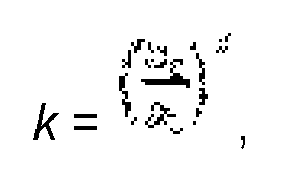
- Procédé selon l'une quelconque des revendications 1 à 4, dans lequel le coefficient de compensation est déterminé par
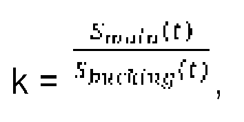
- Procédé selon l'une quelconque des revendications précédentes, comprenant en outre la sélection d'un modèle sur la base de la correspondance du signal compensé synthétique avec le signal compensé pour estimer la propriété de la formation.
- Système (100) pour estimer une propriété d'une formation terrestre (106a, 106b) pénétrée par un trou de forage (102, 202), le système (100) comprenant :un support (104) configuré pour être transporté à travers un trou de forage (102, 202) ;un émetteur (222, 422) disposé sur le support (104, 304, 404) et configuré pour transmettre des champs électromagnétiques transitoires ;un premier récepteur (224, 324, 424a, 424b) disposé sur le support (104, 304, 404) à une première distance de l'émetteur (222, 422) et configuré pour recevoir des signaux provenant de l'émetteur (222, 422) ; etun deuxième récepteur (224, 324, 424a, 424b) disposé sur le support (104, 304, 404) à une deuxième distance de l'émetteur (222, 422) et configuré pour recevoir des signaux provenant de l'émetteur (222, 422) ;un processeur configuré pour estimer une propriété de la formation (106a, 106b, 206), le système (100) configuré pour :générer un premier champ électromagnétique transitoire avec l'émetteur (222, 422) lorsque le support (104) est situé à l'extérieur du trou de forage (102, 202) ;recevoir au niveau du premier récepteur (224, 324, 424a, 424b) un premier signal mesuré dû au premier champ électromagnétique transitoire, le premier signal mesuré affecté par une conductivité finie, non nulle du support (104) ;recevoir au niveau du deuxième récepteur (224, 324, 424a, 424b) un deuxième signal mesuré dû au premier champ électromagnétique transitoire, le deuxième signal mesuré affecté par une conductivité finie, non nulle du support (104) ;calculer, avec un processeur, un coefficient de compensation k en utilisant le premier signal mesuré et le deuxième signal mesuré, le coefficient de compensation basé sur un rapport du premier signal mesuré et du deuxième signal mesuré ;générer un deuxième champ électromagnétique transitoire en utilisant l'émetteur (222, 422) sur le support (104, 304, 404) lorsque le support (104, 304, 404) est disposé au sein du trou de forage (102, 202) ; caractérisé par le système étant en outre configuré pourrecevoir un troisième signal mesuré au niveau du premier récepteur (224, 324, 424a, 424b), le troisième signal mesuré étant un signal généré en présence de la formation dû au deuxième champ électromagnétique transitoire ;recevoir un quatrième signal mesuré au niveau du deuxième récepteur (224, 324, 424a, 424b), le quatrième signal mesuré étant un signal généré en présence de la formation dû au deuxième champ électromagnétique transitoire ;calculer, avec le processeur, un signal compensé en utilisant le coefficient de compensation k, le troisième signal mesuré, et le quatrième signal mesuré ;calculer, avec le processeur, un premier signal de formation synthétique du premier récepteur (224, 324, 424a, 424b) représentant un signal reçu par le premier récepteur (224, 324, 424a, 424b) en l'absence du support (104, 304, 404) ;calculer, avec le processeur, un deuxième signal de formation synthétique du deuxième récepteur (224, 324, 424a, 424b) représentant un signal reçu par le deuxième récepteur (224, 324, 424a, 424b) en l'absence du support (104, 304, 404) ;calculer, avec le processeur, un troisième signal de formation synthétique en appliquant une intégrale de Duhamel au premier signal mesuré et au premier signal de formation synthétique ;calculer, avec le processeur, un quatrième signal de formation synthétique en appliquant une intégrale de Duhamel au deuxième signal mesuré et au deuxième signal de formation synthétique ;calculer un signal compensé synthétique en utilisant le coefficient de compensation calculé k, le troisième signal de formation synthétique, et le quatrième signal de formation synthétique ;mettre en œuvre, avec le processeur, une inversion d'un modèle de formation pour estimer une propriété de la formation de telle sorte qu'un signal compensé synthétique inversé et un signal compensé inversé coïncident au sein d'une plage temporelle prédéterminée ;dans lequel le premier signal mesuré et le deuxième signal mesuré sont chacun des signaux qui sont non affectés par la formation (106a, 106b, 206).
- Système (100) selon la revendication 8, dans lequel le signal compensé mesuré comprend : ΔS(t) = Smain (t) - kS bucking (t), dans lequel ΔS(t) est le signal compensé calculé, Smain (t) est le troisième signal mesuré, et Sbucking (t) est le quatrième signal mesuré.
- Système (100) selon l'une quelconque des revendications 8 ou 9, dans lequel le signal compensé synthétique comprend : ΔScon (t) = Scon main (t)-kScon bucking (t), dans lequel ΔScon(t) est le signal compensé synthétique, Scon main (t) est le troisième signal de formation synthétique, et Scon bucking (t) est le quatrième signal de formation synthétique.
- Système (100) selon l'une quelconque des revendications 8 à 10, dans lequel le coefficient de compensation est déterminé par :

- Système (100) selon l'une quelconque des revendications 8 à 10, dans lequel le coefficient de compensation est déterminé par
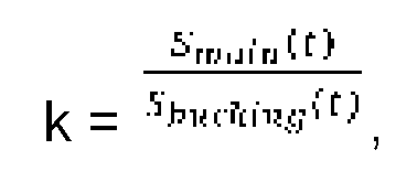
- Système (100) selon l'une quelconque des revendications 8 à 12, dans lequel l'estimation d'une propriété de la formation (106a, 106b, 206) comprend la sélection d'un modèle sur la base d'une correspondance du signal compensé synthétique avec le signal compensé.
Applications Claiming Priority (2)
| Application Number | Priority Date | Filing Date | Title |
|---|---|---|---|
| US15/045,808 US10197695B2 (en) | 2016-02-17 | 2016-02-17 | Method and apparatus for estimating formation properties using transient electromagnetic measurements while drilling |
| PCT/US2017/017928 WO2017142920A1 (fr) | 2016-02-17 | 2017-02-15 | Procédé et appareil pour estimer des propriétés de formations en utilisant des mesures électromagnétiques transitoires pendant le forage |
Publications (3)
| Publication Number | Publication Date |
|---|---|
| EP3417146A1 EP3417146A1 (fr) | 2018-12-26 |
| EP3417146A4 EP3417146A4 (fr) | 2019-12-25 |
| EP3417146B1 true EP3417146B1 (fr) | 2021-07-28 |
Family
ID=59562060
Family Applications (1)
| Application Number | Title | Priority Date | Filing Date |
|---|---|---|---|
| EP17753738.8A Active EP3417146B1 (fr) | 2016-02-17 | 2017-02-15 | Procédé et appareil pour estimer des propriétés de formations en utilisant des mesures électromagnétiques transitoires pendant le forage |
Country Status (4)
| Country | Link |
|---|---|
| US (1) | US10197695B2 (fr) |
| EP (1) | EP3417146B1 (fr) |
| BR (1) | BR112018016152B1 (fr) |
| WO (1) | WO2017142920A1 (fr) |
Families Citing this family (10)
| Publication number | Priority date | Publication date | Assignee | Title |
|---|---|---|---|---|
| US10669840B2 (en) * | 2015-10-27 | 2020-06-02 | Baker Hughes, A Ge Company, Llc | Downhole system having tubular with signal conductor and method |
| US10197695B2 (en) * | 2016-02-17 | 2019-02-05 | Baker Hughes, A Ge Company, Llc | Method and apparatus for estimating formation properties using transient electromagnetic measurements while drilling |
| US10156655B2 (en) | 2016-03-08 | 2018-12-18 | Baker Hughes, A Ge Company, Llc | Method and apparatus for measurement of pipe signals for downhole transient electromagnetic processing |
| US10261210B2 (en) | 2016-03-09 | 2019-04-16 | Baker Hughes, A Ge Company, Llc | Method and apparatus for active suppression of pipe signals in transient electromagnetic measurements |
| US10162076B2 (en) | 2016-03-14 | 2018-12-25 | Baker Hughes, A Ge Company, Llc | Method and apparatus for correction of transient electromagnetic signals to remove a pipe response |
| BR112019006604A2 (pt) * | 2016-11-04 | 2019-07-02 | Halliburton Energy Services Inc | sistema rotativo direcionável, sistema rotativo de perfuração e método para perfurar um furo de poço |
| CN111434887A (zh) * | 2018-12-25 | 2020-07-21 | 天津大学青岛海洋技术研究院 | 一种同轴一发八收瞬变电磁勘探测井仪器 |
| CN109655925B (zh) * | 2019-01-28 | 2023-10-03 | 长江水利委员会长江科学院 | 快速移动式堤防孔洞瞬变电磁连续探测系统及方法 |
| CN112213792B (zh) * | 2020-09-07 | 2023-05-16 | 煤炭科学技术研究院有限公司 | 一种基于瞬变电磁法的含水地质体富水性预测方法 |
| US12560075B2 (en) * | 2023-06-12 | 2026-02-24 | Halliburton Energy Services, Inc. | Gradational resistivity models with local anisotropy for distance to bed boundary inversion |
Family Cites Families (39)
| Publication number | Priority date | Publication date | Assignee | Title |
|---|---|---|---|---|
| EP0665958B1 (fr) | 1993-07-21 | 1999-01-13 | Western Atlas International, Inc. | Procede de determination de la resistivite d'une formation au moyen des mesures combinees obtenues par des instruments de diagraphie inductive et galvanique |
| US5892361A (en) * | 1994-03-14 | 1999-04-06 | Baker Hughes Incorporated | Use of raw amplitude and phase in propagation resistivity measurements to measure borehole environmental parameters |
| CA2154378C (fr) * | 1994-08-01 | 2006-03-21 | Larry W. Thompson | Methode et appareil de mesure dans un trou de sonde |
| US5581024A (en) * | 1994-10-20 | 1996-12-03 | Baker Hughes Incorporated | Downhole depth correlation and computation apparatus and methods for combining multiple borehole measurements |
| US6204667B1 (en) * | 1998-03-18 | 2001-03-20 | Geophex, Ltd. | Electromagnetic gradiometer having a primary detector and a plurality of secondary detectors |
| US6586939B1 (en) * | 1999-12-24 | 2003-07-01 | Baker Hughes Incorporated | Method and apparatus for reducing the effects of parasitic and galvanic currents in a resistivity measuring tool |
| US7598741B2 (en) * | 1999-12-24 | 2009-10-06 | Baker Hughes Incorporated | Method and apparatus for internal calibration in induction logging instruments |
| CA2463883A1 (fr) * | 2001-11-13 | 2003-05-22 | Weatherford/Lamb, Inc. | Systeme et procede de compensation de puits pour appareil de diagraphie de resistivite |
| US20040183538A1 (en) | 2003-03-19 | 2004-09-23 | Tilman Hanstein | Structure for electromagnetic induction well logging apparatus |
| US6891376B2 (en) | 2003-07-01 | 2005-05-10 | Kjt Enterprises, Inc. | Method for attenuating conductive sonde mandrel effects in an electromagnetic induction well logging apparatus |
| US7027922B2 (en) | 2003-08-25 | 2006-04-11 | Baker Hughes Incorporated | Deep resistivity transient method for MWD applications using asymptotic filtering |
| US7026820B2 (en) * | 2003-11-04 | 2006-04-11 | Halliburton Energy Services, Inc. | Method and apparatus for minimizing direct coupling for downhole logging devices |
| US7046009B2 (en) * | 2003-12-24 | 2006-05-16 | Baker Hughes Incorporated | Method for measuring transient electromagnetic components to perform deep geosteering while drilling |
| US7408355B1 (en) * | 2004-05-07 | 2008-08-05 | Baker Hughes Incorporated | Borehole conductivity simulator verification and transverse coil balancing |
| US8030935B2 (en) * | 2004-10-15 | 2011-10-04 | Halliburton Energy Services, Inc. | Minimizing the effect of borehole current in tensor induction logging tools |
| US7501829B2 (en) | 2005-02-28 | 2009-03-10 | Schlumberger Technology Corporation | Extra bucking coils as an alternative way to balance induction arrays |
| US8132453B2 (en) | 2005-05-10 | 2012-03-13 | Schlumberger Technology Corporation | Method for analysis of pressure response in underground formations |
| US20070216416A1 (en) | 2006-03-15 | 2007-09-20 | Baker Hughes Incorporated | Electromagnetic and Magnetostatic Shield To Perform Measurements Ahead of the Drill Bit |
| US7265649B1 (en) * | 2007-02-19 | 2007-09-04 | Hall David R | Flexible inductive resistivity device |
| US7567869B2 (en) | 2007-04-27 | 2009-07-28 | Baker Hughes Incorporated | Induction tool for detail evaluation of near borehole zone |
| US8332152B2 (en) | 2008-03-19 | 2012-12-11 | Baker Hughes Incorporated | Method and apparatus for eliminating drill effect in pulse induction measurements |
| US7994790B2 (en) * | 2008-03-19 | 2011-08-09 | Baker Hughes Incorporated | Electromagnetic and magnetostatic shield to perform measurements ahead of the drill bit |
| US8008919B2 (en) | 2008-03-25 | 2011-08-30 | Baker Hughes Incorporated | Method for compensating drill pipe and near-borehole effect on and electronic noise in transient resistivity measurements |
| US8278930B2 (en) | 2008-05-01 | 2012-10-02 | Baker Hughes Incorporated | Deep MWD resistivity measurements using EM shielding |
| US8035392B2 (en) | 2008-10-17 | 2011-10-11 | Baker Hughes Incorporated | Method and apparatus for while-drilling transient resistivity measurements |
| US8115491B2 (en) | 2009-01-07 | 2012-02-14 | WesternGreco L.L.C. | Providing a tow cable having plural electromagnetic receivers and one or more electromagnetic sources |
| US9588250B2 (en) | 2010-04-14 | 2017-03-07 | Baker Hughes Incorporated | Three-coil system with short nonconductive inserts for transient MWD resistivity measurements |
| US8762107B2 (en) * | 2010-09-27 | 2014-06-24 | Baker Hughes Incorporated | Triaxial induction calibration without prior knowledge of the calibration area's ground conductivity |
| US20120209528A1 (en) | 2011-02-10 | 2012-08-16 | Baker Hughes Incorporated | Inversion-Based Method to Correct for the Pipe Residual Signal in Transient MWD Measurements |
| US9310511B2 (en) * | 2012-11-01 | 2016-04-12 | Baker Hughes Incorporated | Apparatus and method for deep transient resistivity measurement |
| US9575205B2 (en) | 2013-01-17 | 2017-02-21 | Pgs Geophysical As | Uncertainty-based frequency-selected inversion of electromagnetic geophysical data |
| US9880307B2 (en) | 2013-10-24 | 2018-01-30 | Baker Hughes Incorporated | Induction logging sensor |
| US9482777B2 (en) | 2014-02-21 | 2016-11-01 | Baker Hughes Incorporated | Transient electromagnetic tool mounted on reduced conductivity tubular |
| US10197695B2 (en) * | 2016-02-17 | 2019-02-05 | Baker Hughes, A Ge Company, Llc | Method and apparatus for estimating formation properties using transient electromagnetic measurements while drilling |
| US9857499B2 (en) * | 2016-02-19 | 2018-01-02 | Baker Hughes, A Ge Company, Llc | Downhole transient resistivity measurements |
| US10156655B2 (en) * | 2016-03-08 | 2018-12-18 | Baker Hughes, A Ge Company, Llc | Method and apparatus for measurement of pipe signals for downhole transient electromagnetic processing |
| US10261210B2 (en) * | 2016-03-09 | 2019-04-16 | Baker Hughes, A Ge Company, Llc | Method and apparatus for active suppression of pipe signals in transient electromagnetic measurements |
| US10162076B2 (en) * | 2016-03-14 | 2018-12-25 | Baker Hughes, A Ge Company, Llc | Method and apparatus for correction of transient electromagnetic signals to remove a pipe response |
| US10254430B2 (en) * | 2016-03-17 | 2019-04-09 | Baker Hughes, A Ge Company, Llc | Downhole deep transient measurements with improved sensors |
-
2016
- 2016-02-17 US US15/045,808 patent/US10197695B2/en active Active
-
2017
- 2017-02-15 BR BR112018016152-7A patent/BR112018016152B1/pt active IP Right Grant
- 2017-02-15 WO PCT/US2017/017928 patent/WO2017142920A1/fr not_active Ceased
- 2017-02-15 EP EP17753738.8A patent/EP3417146B1/fr active Active
Also Published As
| Publication number | Publication date |
|---|---|
| EP3417146A1 (fr) | 2018-12-26 |
| BR112018016152A2 (pt) | 2018-12-18 |
| US10197695B2 (en) | 2019-02-05 |
| BR112018016152B1 (pt) | 2022-11-01 |
| WO2017142920A1 (fr) | 2017-08-24 |
| US20170235012A1 (en) | 2017-08-17 |
| EP3417146A4 (fr) | 2019-12-25 |
Similar Documents
| Publication | Publication Date | Title |
|---|---|---|
| US10197695B2 (en) | Method and apparatus for estimating formation properties using transient electromagnetic measurements while drilling | |
| US10139517B2 (en) | Hybrid image of earth formation based on transient electromagnetc measurements | |
| US8049507B2 (en) | Transient EM for geosteering and LWD/wireline formation evaluation | |
| EP3420347B1 (fr) | Mesures transitoires de résistivité de fond de puits | |
| EP3080389B1 (fr) | Détermination et affichage de résistivité apparente de données électromagnétiques transitoires de fond de trou | |
| EP3427091B1 (fr) | Procédé et appareil pour la mesure de signaux de tubulure pour le traitement de signaux électromagnétiques transitoires de fond de trou | |
| EP3427090B1 (fr) | Procédé et appareil de suppression active de signaux de tuyauterie dans des mesures électromagnétiques transitoires | |
| EP3108272B1 (fr) | Outil de mesure de transitoires électromagnétiques monté sur une tubulure à conductivité réduite | |
| CA2588496A1 (fr) | Blindage magnetostatique et electromagnetique permettant d'effectuer des mesures en avant du trepan | |
| EP3430444B1 (fr) | Procédé et appareil de correction de signaux électromagnétiques transitoires pour éliminer une réponse de tuyau | |
| WO2010057070A2 (fr) | Procédé de mesure transitoire de résistivité en profondeur pendant le forage | |
| US10353104B2 (en) | Carbonate permeability by pore typing | |
| US20100213943A1 (en) | Method for accentuating signal from ahead of the bit | |
| US20210072420A1 (en) | Low frequency complex resistivity measurement in a formation | |
| US9229125B2 (en) | TDEM forward focusing system for downhole use | |
| WO2010022014A2 (fr) | Traitement de données de résistivité azimutale dans un gradient de résistivité | |
| WO2007116317A2 (fr) | Blindage électromagnétique et magnétostatique permettant d'effectuer des mesures en avant du trépan |
Legal Events
| Date | Code | Title | Description |
|---|---|---|---|
| STAA | Information on the status of an ep patent application or granted ep patent |
Free format text: STATUS: THE INTERNATIONAL PUBLICATION HAS BEEN MADE |
|
| PUAI | Public reference made under article 153(3) epc to a published international application that has entered the european phase |
Free format text: ORIGINAL CODE: 0009012 |
|
| STAA | Information on the status of an ep patent application or granted ep patent |
Free format text: STATUS: REQUEST FOR EXAMINATION WAS MADE |
|
| 17P | Request for examination filed |
Effective date: 20180917 |
|
| AK | Designated contracting states |
Kind code of ref document: A1 Designated state(s): AL AT BE BG CH CY CZ DE DK EE ES FI FR GB GR HR HU IE IS IT LI LT LU LV MC MK MT NL NO PL PT RO RS SE SI SK SM TR |
|
| AX | Request for extension of the european patent |
Extension state: BA ME |
|
| DAV | Request for validation of the european patent (deleted) | ||
| DAX | Request for extension of the european patent (deleted) | ||
| A4 | Supplementary search report drawn up and despatched |
Effective date: 20191127 |
|
| RIC1 | Information provided on ipc code assigned before grant |
Ipc: G01V 3/28 20060101ALI20191121BHEP Ipc: G01V 3/38 20060101ALI20191121BHEP Ipc: E21B 47/00 20120101ALI20191121BHEP Ipc: G01V 3/26 20060101AFI20191121BHEP |
|
| REG | Reference to a national code |
Ref country code: DE Ref legal event code: R079 Ref document number: 602017042930 Country of ref document: DE Free format text: PREVIOUS MAIN CLASS: E21B0047000000 Ipc: G01V0003260000 |
|
| RIC1 | Information provided on ipc code assigned before grant |
Ipc: E21B 47/13 20120101ALI20201125BHEP Ipc: G01V 3/28 20060101ALI20201125BHEP Ipc: E21B 49/00 20060101ALI20201125BHEP Ipc: G01V 3/26 20060101AFI20201125BHEP Ipc: G01V 3/38 20060101ALI20201125BHEP |
|
| GRAP | Despatch of communication of intention to grant a patent |
Free format text: ORIGINAL CODE: EPIDOSNIGR1 |
|
| STAA | Information on the status of an ep patent application or granted ep patent |
Free format text: STATUS: GRANT OF PATENT IS INTENDED |
|
| INTG | Intention to grant announced |
Effective date: 20210127 |
|
| GRAS | Grant fee paid |
Free format text: ORIGINAL CODE: EPIDOSNIGR3 |
|
| RAP3 | Party data changed (applicant data changed or rights of an application transferred) |
Owner name: BAKER HUGHES HOLDINGS LLC |
|
| GRAA | (expected) grant |
Free format text: ORIGINAL CODE: 0009210 |
|
| STAA | Information on the status of an ep patent application or granted ep patent |
Free format text: STATUS: THE PATENT HAS BEEN GRANTED |
|
| AK | Designated contracting states |
Kind code of ref document: B1 Designated state(s): AL AT BE BG CH CY CZ DE DK EE ES FI FR GB GR HR HU IE IS IT LI LT LU LV MC MK MT NL NO PL PT RO RS SE SI SK SM TR |
|
| REG | Reference to a national code |
Ref country code: GB Ref legal event code: FG4D |
|
| REG | Reference to a national code |
Ref country code: CH Ref legal event code: EP |
|
| REG | Reference to a national code |
Ref country code: DE Ref legal event code: R096 Ref document number: 602017042930 Country of ref document: DE |
|
| REG | Reference to a national code |
Ref country code: AT Ref legal event code: REF Ref document number: 1415200 Country of ref document: AT Kind code of ref document: T Effective date: 20210815 |
|
| REG | Reference to a national code |
Ref country code: IE Ref legal event code: FG4D |
|
| REG | Reference to a national code |
Ref country code: LT Ref legal event code: MG9D |
|
| REG | Reference to a national code |
Ref country code: NL Ref legal event code: MP Effective date: 20210728 |
|
| REG | Reference to a national code |
Ref country code: AT Ref legal event code: MK05 Ref document number: 1415200 Country of ref document: AT Kind code of ref document: T Effective date: 20210728 |
|
| REG | Reference to a national code |
Ref country code: NO Ref legal event code: T2 Effective date: 20210728 |
|
| PG25 | Lapsed in a contracting state [announced via postgrant information from national office to epo] |
Ref country code: RS Free format text: LAPSE BECAUSE OF FAILURE TO SUBMIT A TRANSLATION OF THE DESCRIPTION OR TO PAY THE FEE WITHIN THE PRESCRIBED TIME-LIMIT Effective date: 20210728 Ref country code: SE Free format text: LAPSE BECAUSE OF FAILURE TO SUBMIT A TRANSLATION OF THE DESCRIPTION OR TO PAY THE FEE WITHIN THE PRESCRIBED TIME-LIMIT Effective date: 20210728 Ref country code: HR Free format text: LAPSE BECAUSE OF FAILURE TO SUBMIT A TRANSLATION OF THE DESCRIPTION OR TO PAY THE FEE WITHIN THE PRESCRIBED TIME-LIMIT Effective date: 20210728 Ref country code: LT Free format text: LAPSE BECAUSE OF FAILURE TO SUBMIT A TRANSLATION OF THE DESCRIPTION OR TO PAY THE FEE WITHIN THE PRESCRIBED TIME-LIMIT Effective date: 20210728 Ref country code: AT Free format text: LAPSE BECAUSE OF FAILURE TO SUBMIT A TRANSLATION OF THE DESCRIPTION OR TO PAY THE FEE WITHIN THE PRESCRIBED TIME-LIMIT Effective date: 20210728 Ref country code: BG Free format text: LAPSE BECAUSE OF FAILURE TO SUBMIT A TRANSLATION OF THE DESCRIPTION OR TO PAY THE FEE WITHIN THE PRESCRIBED TIME-LIMIT Effective date: 20211028 Ref country code: PT Free format text: LAPSE BECAUSE OF FAILURE TO SUBMIT A TRANSLATION OF THE DESCRIPTION OR TO PAY THE FEE WITHIN THE PRESCRIBED TIME-LIMIT Effective date: 20211129 Ref country code: NL Free format text: LAPSE BECAUSE OF FAILURE TO SUBMIT A TRANSLATION OF THE DESCRIPTION OR TO PAY THE FEE WITHIN THE PRESCRIBED TIME-LIMIT Effective date: 20210728 Ref country code: FI Free format text: LAPSE BECAUSE OF FAILURE TO SUBMIT A TRANSLATION OF THE DESCRIPTION OR TO PAY THE FEE WITHIN THE PRESCRIBED TIME-LIMIT Effective date: 20210728 Ref country code: ES Free format text: LAPSE BECAUSE OF FAILURE TO SUBMIT A TRANSLATION OF THE DESCRIPTION OR TO PAY THE FEE WITHIN THE PRESCRIBED TIME-LIMIT Effective date: 20210728 |
|
| PG25 | Lapsed in a contracting state [announced via postgrant information from national office to epo] |
Ref country code: PL Free format text: LAPSE BECAUSE OF FAILURE TO SUBMIT A TRANSLATION OF THE DESCRIPTION OR TO PAY THE FEE WITHIN THE PRESCRIBED TIME-LIMIT Effective date: 20210728 Ref country code: LV Free format text: LAPSE BECAUSE OF FAILURE TO SUBMIT A TRANSLATION OF THE DESCRIPTION OR TO PAY THE FEE WITHIN THE PRESCRIBED TIME-LIMIT Effective date: 20210728 Ref country code: GR Free format text: LAPSE BECAUSE OF FAILURE TO SUBMIT A TRANSLATION OF THE DESCRIPTION OR TO PAY THE FEE WITHIN THE PRESCRIBED TIME-LIMIT Effective date: 20211029 |
|
| PG25 | Lapsed in a contracting state [announced via postgrant information from national office to epo] |
Ref country code: DK Free format text: LAPSE BECAUSE OF FAILURE TO SUBMIT A TRANSLATION OF THE DESCRIPTION OR TO PAY THE FEE WITHIN THE PRESCRIBED TIME-LIMIT Effective date: 20210728 |
|
| REG | Reference to a national code |
Ref country code: DE Ref legal event code: R097 Ref document number: 602017042930 Country of ref document: DE |
|
| PG25 | Lapsed in a contracting state [announced via postgrant information from national office to epo] |
Ref country code: SM Free format text: LAPSE BECAUSE OF FAILURE TO SUBMIT A TRANSLATION OF THE DESCRIPTION OR TO PAY THE FEE WITHIN THE PRESCRIBED TIME-LIMIT Effective date: 20210728 Ref country code: SK Free format text: LAPSE BECAUSE OF FAILURE TO SUBMIT A TRANSLATION OF THE DESCRIPTION OR TO PAY THE FEE WITHIN THE PRESCRIBED TIME-LIMIT Effective date: 20210728 Ref country code: RO Free format text: LAPSE BECAUSE OF FAILURE TO SUBMIT A TRANSLATION OF THE DESCRIPTION OR TO PAY THE FEE WITHIN THE PRESCRIBED TIME-LIMIT Effective date: 20210728 Ref country code: EE Free format text: LAPSE BECAUSE OF FAILURE TO SUBMIT A TRANSLATION OF THE DESCRIPTION OR TO PAY THE FEE WITHIN THE PRESCRIBED TIME-LIMIT Effective date: 20210728 Ref country code: CZ Free format text: LAPSE BECAUSE OF FAILURE TO SUBMIT A TRANSLATION OF THE DESCRIPTION OR TO PAY THE FEE WITHIN THE PRESCRIBED TIME-LIMIT Effective date: 20210728 Ref country code: AL Free format text: LAPSE BECAUSE OF FAILURE TO SUBMIT A TRANSLATION OF THE DESCRIPTION OR TO PAY THE FEE WITHIN THE PRESCRIBED TIME-LIMIT Effective date: 20210728 |
|
| PLBE | No opposition filed within time limit |
Free format text: ORIGINAL CODE: 0009261 |
|
| STAA | Information on the status of an ep patent application or granted ep patent |
Free format text: STATUS: NO OPPOSITION FILED WITHIN TIME LIMIT |
|
| 26N | No opposition filed |
Effective date: 20220429 |
|
| PG25 | Lapsed in a contracting state [announced via postgrant information from national office to epo] |
Ref country code: IT Free format text: LAPSE BECAUSE OF FAILURE TO SUBMIT A TRANSLATION OF THE DESCRIPTION OR TO PAY THE FEE WITHIN THE PRESCRIBED TIME-LIMIT Effective date: 20210728 |
|
| REG | Reference to a national code |
Ref country code: DE Ref legal event code: R119 Ref document number: 602017042930 Country of ref document: DE |
|
| PG25 | Lapsed in a contracting state [announced via postgrant information from national office to epo] |
Ref country code: MC Free format text: LAPSE BECAUSE OF FAILURE TO SUBMIT A TRANSLATION OF THE DESCRIPTION OR TO PAY THE FEE WITHIN THE PRESCRIBED TIME-LIMIT Effective date: 20210728 |
|
| REG | Reference to a national code |
Ref country code: CH Ref legal event code: PL |
|
| REG | Reference to a national code |
Ref country code: BE Ref legal event code: MM Effective date: 20220228 |
|
| PG25 | Lapsed in a contracting state [announced via postgrant information from national office to epo] |
Ref country code: LU Free format text: LAPSE BECAUSE OF NON-PAYMENT OF DUE FEES Effective date: 20220215 |
|
| PG25 | Lapsed in a contracting state [announced via postgrant information from national office to epo] |
Ref country code: FR Free format text: LAPSE BECAUSE OF NON-PAYMENT OF DUE FEES Effective date: 20220228 |
|
| PG25 | Lapsed in a contracting state [announced via postgrant information from national office to epo] |
Ref country code: LI Free format text: LAPSE BECAUSE OF NON-PAYMENT OF DUE FEES Effective date: 20220228 Ref country code: IE Free format text: LAPSE BECAUSE OF NON-PAYMENT OF DUE FEES Effective date: 20220215 Ref country code: DE Free format text: LAPSE BECAUSE OF NON-PAYMENT OF DUE FEES Effective date: 20220901 Ref country code: CH Free format text: LAPSE BECAUSE OF NON-PAYMENT OF DUE FEES Effective date: 20220228 |
|
| PG25 | Lapsed in a contracting state [announced via postgrant information from national office to epo] |
Ref country code: BE Free format text: LAPSE BECAUSE OF NON-PAYMENT OF DUE FEES Effective date: 20220228 |
|
| P01 | Opt-out of the competence of the unified patent court (upc) registered |
Effective date: 20230526 |
|
| PG25 | Lapsed in a contracting state [announced via postgrant information from national office to epo] |
Ref country code: HU Free format text: LAPSE BECAUSE OF FAILURE TO SUBMIT A TRANSLATION OF THE DESCRIPTION OR TO PAY THE FEE WITHIN THE PRESCRIBED TIME-LIMIT; INVALID AB INITIO Effective date: 20170215 |
|
| PG25 | Lapsed in a contracting state [announced via postgrant information from national office to epo] |
Ref country code: MK Free format text: LAPSE BECAUSE OF FAILURE TO SUBMIT A TRANSLATION OF THE DESCRIPTION OR TO PAY THE FEE WITHIN THE PRESCRIBED TIME-LIMIT Effective date: 20210728 Ref country code: CY Free format text: LAPSE BECAUSE OF FAILURE TO SUBMIT A TRANSLATION OF THE DESCRIPTION OR TO PAY THE FEE WITHIN THE PRESCRIBED TIME-LIMIT Effective date: 20210728 |
|
| PG25 | Lapsed in a contracting state [announced via postgrant information from national office to epo] |
Ref country code: MT Free format text: LAPSE BECAUSE OF FAILURE TO SUBMIT A TRANSLATION OF THE DESCRIPTION OR TO PAY THE FEE WITHIN THE PRESCRIBED TIME-LIMIT Effective date: 20210728 |
|
| PG25 | Lapsed in a contracting state [announced via postgrant information from national office to epo] |
Ref country code: TR Free format text: LAPSE BECAUSE OF FAILURE TO SUBMIT A TRANSLATION OF THE DESCRIPTION OR TO PAY THE FEE WITHIN THE PRESCRIBED TIME-LIMIT Effective date: 20210728 |
|
| PGFP | Annual fee paid to national office [announced via postgrant information from national office to epo] |
Ref country code: GB Payment date: 20260121 Year of fee payment: 10 |
|
| PGFP | Annual fee paid to national office [announced via postgrant information from national office to epo] |
Ref country code: NO Payment date: 20260123 Year of fee payment: 10 |