EP3417695A1 - System zur vernichtung von samen in ernterückständen vor der entladung aus einer landwirtschaftlichen erntemaschine - Google Patents
System zur vernichtung von samen in ernterückständen vor der entladung aus einer landwirtschaftlichen erntemaschine Download PDFInfo
- Publication number
- EP3417695A1 EP3417695A1 EP18178810.0A EP18178810A EP3417695A1 EP 3417695 A1 EP3417695 A1 EP 3417695A1 EP 18178810 A EP18178810 A EP 18178810A EP 3417695 A1 EP3417695 A1 EP 3417695A1
- Authority
- EP
- European Patent Office
- Prior art keywords
- seeds
- cylindrical body
- roller
- shearing surface
- cylindrical
- Prior art date
- Legal status (The legal status is an assumption and is not a legal conclusion. Google has not performed a legal analysis and makes no representation as to the accuracy of the status listed.)
- Granted
Links
Images





Classifications
-
- A—HUMAN NECESSITIES
- A01—AGRICULTURE; FORESTRY; ANIMAL HUSBANDRY; HUNTING; TRAPPING; FISHING
- A01D—HARVESTING; MOWING
- A01D41/00—Combines, i.e. harvesters or mowers combined with threshing devices
- A01D41/12—Details of combines
- A01D41/1243—Devices for laying-out or distributing the straw
-
- A—HUMAN NECESSITIES
- A01—AGRICULTURE; FORESTRY; ANIMAL HUSBANDRY; HUNTING; TRAPPING; FISHING
- A01F—PROCESSING OF HARVESTED PRODUCE; HAY OR STRAW PRESSES; DEVICES FOR STORING AGRICULTURAL OR HORTICULTURAL PRODUCE
- A01F12/00—Parts or details of threshing apparatus
-
- A—HUMAN NECESSITIES
- A01—AGRICULTURE; FORESTRY; ANIMAL HUSBANDRY; HUNTING; TRAPPING; FISHING
- A01F—PROCESSING OF HARVESTED PRODUCE; HAY OR STRAW PRESSES; DEVICES FOR STORING AGRICULTURAL OR HORTICULTURAL PRODUCE
- A01F12/00—Parts or details of threshing apparatus
- A01F12/40—Arrangements of straw crushers or cutters
-
- B—PERFORMING OPERATIONS; TRANSPORTING
- B02—CRUSHING, PULVERISING, OR DISINTEGRATING; PREPARATORY TREATMENT OF GRAIN FOR MILLING
- B02C—CRUSHING, PULVERISING, OR DISINTEGRATING IN GENERAL; MILLING GRAIN
- B02C13/00—Disintegrating by mills having rotary beater elements ; Hammer mills
- B02C13/20—Disintegrating by mills having rotary beater elements ; Hammer mills with two or more co-operating rotors
- B02C13/205—Disintegrating by mills having rotary beater elements ; Hammer mills with two or more co-operating rotors arranged concentrically
-
- B—PERFORMING OPERATIONS; TRANSPORTING
- B02—CRUSHING, PULVERISING, OR DISINTEGRATING; PREPARATORY TREATMENT OF GRAIN FOR MILLING
- B02C—CRUSHING, PULVERISING, OR DISINTEGRATING IN GENERAL; MILLING GRAIN
- B02C19/00—Other disintegrating devices or methods
- B02C19/22—Crushing mills with screw-shaped crushing means
-
- B—PERFORMING OPERATIONS; TRANSPORTING
- B02—CRUSHING, PULVERISING, OR DISINTEGRATING; PREPARATORY TREATMENT OF GRAIN FOR MILLING
- B02C—CRUSHING, PULVERISING, OR DISINTEGRATING IN GENERAL; MILLING GRAIN
- B02C25/00—Control arrangements specially adapted for crushing or disintegrating
-
- B—PERFORMING OPERATIONS; TRANSPORTING
- B02—CRUSHING, PULVERISING, OR DISINTEGRATING; PREPARATORY TREATMENT OF GRAIN FOR MILLING
- B02C—CRUSHING, PULVERISING, OR DISINTEGRATING IN GENERAL; MILLING GRAIN
- B02C4/00—Crushing or disintegrating by roller mills
- B02C4/02—Crushing or disintegrating by roller mills with two or more rollers
- B02C4/06—Crushing or disintegrating by roller mills with two or more rollers specially adapted for milling grain
-
- B—PERFORMING OPERATIONS; TRANSPORTING
- B02—CRUSHING, PULVERISING, OR DISINTEGRATING; PREPARATORY TREATMENT OF GRAIN FOR MILLING
- B02C—CRUSHING, PULVERISING, OR DISINTEGRATING IN GENERAL; MILLING GRAIN
- B02C4/00—Crushing or disintegrating by roller mills
- B02C4/28—Details
- B02C4/32—Adjusting, applying pressure to, or controlling the distance between, milling members
- B02C4/38—Adjusting, applying pressure to, or controlling the distance between, milling members in grain mills
-
- A—HUMAN NECESSITIES
- A01—AGRICULTURE; FORESTRY; ANIMAL HUSBANDRY; HUNTING; TRAPPING; FISHING
- A01D—HARVESTING; MOWING
- A01D41/00—Combines, i.e. harvesters or mowers combined with threshing devices
- A01D41/12—Details of combines
Definitions
- the present invention relates generally to residue handling systems in combine harvesters, and more particularly to a system and method for destroying seeds, such as weed seeds, in residual material separated from crops prior to discharging the residual material from the harvester.
- Axially arranged rotary threshing or separating systems have long been in use in combine harvesters for threshing crops to separate grain from crop residue.
- These axially arranged systems typically include at least one cylindrical rotor rotated within a cage or concave, with the rotor and surrounding concave being oriented so as to extend forwardly to rearwardly within the combine.
- crop material is fed or directed into a circumferential passage between the rotor and the concave.
- the crop material is carried rearwardly along a generally helical path through the passage by rotation of the rotor.
- grain is threshed from the crop material.
- Grain and chaff are separated out and drop into a cleaning system which separates the grain from the chaff.
- Stalks and other larger material that remain between the rotor and concave are discharged or expelled at a rear or downstream end of the rotor. Chaff that exits the cleaning system and crop residue that exits the threshing system are directed into a crop residue distribution system.
- the crop residue distribution system can include a rotary beater, chopper or other apparatus that conveys or chops the residue into smaller pieces and propels the crop residue rearwardly towards a distribution chamber or area at the rear end of the combine.
- Crop residue that enters the distribution chamber can either be discharged onto a field as a windrow, or directed into a spreader mounted on or at the rear end of the combine that is operable for spreading the residue over a swath of the field.
- weed control measures have included windrowing of chaff, followed by either burning or collecting the windrows before weeds can sprout.
- Weed control measures have also included pulling a large square baler behind the combine to contain seeds, or using an integrated continuous round baler. Examples of balers are described in U.S. Patent No. 8,313,362 and U.S. Patent No. 8,733,241 , the contents of both patents being incorporated herein by reference in their entireties.
- These weed control measures also add significant time and expense, require additional equipment, and increase the number of equipment passes over the field.
- chaff has a low bulk density, making collection and transportation of the chaff material very inefficient.
- Systems and methods in accordance with the invention are configured to damage seeds in crop residue before the crop residue exits the combine, thereby preventing seeds from germinating after they re-enter the field.
- systems and methods in accordance with the invention avoid the time and expense of conventional weed control measures, such as the time and expense associated with crop tillage, chemical treatment, burning, chaff collection and transport.
- systems and methods in accordance with the invention are implemented during the harvesting operation, requiring no additional equipment or equipment passes over the field. As such, the undesired growth of weeds and crop plants are controlled without disrupting the normal harvesting operation, and without the need for any post-harvesting operations.
- a system for processing seeds that are present in crop material processed by a combine harvester includes at least one first shearing surface, at least one second shearing surface arranged opposite the at least one first shearing surface, and a clearance between the at least one first shearing surface and the at least one second shearing surface.
- the clearance is adapted to receive a flow of crop material containing seeds, and further adapted to convey said flow of crop material between the at least one first shearing surface and the at least one second shearing surface, such that said flow of crop material contacts the at least one first shearing surface and the at least one second shearing surface to damage seeds present in the crop material and prevent the seeds from germinating after exiting the system.
- the at least one first shearing surface moves at a first tangential velocity relative to the system
- the at least one second shearing surface moves at a second tangential velocity relative to the system that is different from the first velocity
- the system includes at least one first cylindrical body and at least one second cylindrical body, wherein the at least one first shearing surface extends along a portion of the at least one first cylindrical body, and the second shearing surface extends along a portion of the at least one second cylindrical body.
- the at least one first cylindrical body includes a first roller having a first shaft and a first helical thread winding around the first shaft.
- the at least one second cylindrical body includes a second roller having a second shaft and a second helical thread winding around the second shaft.
- the at least one first shearing surface includes a radially outwardly-facing edge on the first helical thread
- the at least one second shearing surface includes a radially outwardly-facing edge on the second shaft
- the first helical thread is mated with the second helical thread, such that the radially outwardly-facing edge on the first helical thread faces the radially outwardly-facing edge on the second shaft, the clearance being defined between the radially outwardly-facing edge on the first helical thread and the radially outwardly-facing edge on the second shaft.
- the at least one first cylindrical body includes a plurality of first cylindrical bodies
- the at least one second cylindrical body includes a plurality of second cylindrical bodies.
- the system includes at least one baffle positioned above the at least one first cylindrical body and the at least one second cylindrical body, the baffle positioned to direct crop material to an area between the at least one first cylindrical body and the at least one second cylindrical body.
- the system includes at least one catch pan or crop gathering pan beneath the at least one first cylindrical roller and the at least one second cylindrical roller, the at least one catch pan or crop gathering pan adapted to catch crop material passing between the at least one first cylindrical roller and the at least one second cylindrical roller.
- the system includes at least one frame for attaching the at least one first cylindrical body and the at least one second cylindrical body to a combine harvester.
- the at least one first cylindrical body includes at least one first cylindrical roller that is fixed relative to the at least one frame
- the second cylindrical body includes at least one second cylindrical roller that is movable relative to the at least one frame
- the at least one second cylindrical roller is movable between a home position, in which the at least one second cylindrical roller is spaced a first distance from the at least one first cylindrical roller, and a deflected position, in which the at least one second cylindrical roller is spaced a second distance from the at least one first cylindrical roller, the second distance being greater than the first distance.
- the system includes at least one biasing element that movably connects the at least one second cylindrical roller to the at least one frame, the at least one biasing element exerting a biasing force on the at least one second cylindrical roller to urge the at least one second cylindrical roller toward the home position.
- the at least one first cylindrical body includes a first gearing operable to rotate the at least one first cylindrical body at a first velocity relative to the system
- the at least one second cylindrical body includes a second gearing operable to rotate the at least one second cylindrical body at a second velocity relative to the system that is different from the first velocity
- the at least one first cylindrical body includes at least one drum
- the at least one second cylindrical body includes at least one concave mounted around the at least one drum.
- the at least one first shearing surface includes an outer surface on the at least one drum, the outer surface having a first plurality of projecting elements
- the at least one second shearing surface includes an inner surface inside the at least one concave, the inner surface having a second plurality of projecting elements that intermesh with the first plurality of projection elements on the at least one drum.
- the system includes an adjustment system for adjusting a clearance between the at least one drum and the at least one concave, the adjustment system including a pivot hinge that pivotally connects the at least one concave to the at least one drum, and an adjusting screw rotatable to pivot the at least one concave relative to the at least one drum to change the clearance between the at least one drum and the least one concave.
- the system is mounted on a pivot assembly configured to permit the system for processing seeds to fold downwardly and allow a flow of crop material to bypass the system for processing seeds.
- FIG. 1 illustrates a simplified, side view of one embodiment of a combine harvester 10.
- the combine 10 may be configured the same as or similar to any suitable combine harvester known in the art, such as a conventional style combine or axial combine.
- the combine 10 can include an axially arranged threshing system 12 and a cleaning system 13.
- the threshing system 12 may include a cylindrical rotor 14 rotatably supported within a cage or concave 16 for conveying a flow of crop material in a helical flow path along a circumferential space 18 defined between the rotor 14 and the concave 16.
- the crop e.g., grain, legumes, and/or the like
- the residue e.g., husks, pods and/or the like
- the crop residue may continue along the helical path and may be subsequently discharged through a discharge opening (not shown) defined at a downstream end 22 of the threshing system 12.
- Combine 10 also includes a crop residue discharge system 24 for expelling crop residue from the combine to the field.
- Discharge systems used with combines in accordance with the invention can include a variety of mechanisms for discharging crop residue to the field.
- discharge system 24 includes a spreader 42 for swath spreading.
- discharge system 24 includes an opening 46 near the rear of the combine for windrowing.
- U.S. Patent No. 9,107,349 also assigned to applicant, the contents of said patent being incorporated by reference herein in its entirety.
- Combine 10 further includes a seed processor 50 located downstream of cleaning system 13.
- seed processors in accordance with the invention can take various forms. Therefore, FIG. 1 shows seed processor 50 in schematic form only, with the understanding that its appearance and relative position inside or outside of combine 10 will vary depending on the embodiment.
- seed processor 50 is configured to receive crop residue from cleaning system 13 and destroy or damage seeds through shearing forces, so that when the seeds exit combine 10, the seeds are no longer viable and able to germinate.
- seed processor 50 provides an on-board destruction mechanism 52 inside the combine that destroys seeds, thereby preventing seeds present in crop residue from leaving the combine in a viable state.
- Seed processors 50 in accordance with the invention preferably damage seeds by shear action.
- a seed processor in accordance with the invention can include first and second surfaces facing one another and spaced closely together, forming a narrow passage between the surfaces. Seeds and finer pieces of crop residue can be passed through the narrow passage during processing, while directly or indirectly contacting both the first and second surfaces. As seeds are passed through the passage, the first and second surfaces move in the same general direction along the passage, but at different velocities, thereby introducing a shear effect that destroys the seeds as they pass through the first and second surfaces. By utilizing shear in this manner, seeds can be destroyed inside the combine without resorting to other systems that rely on crushing or impact to break up crop residue. Crushing can have significant power and force requirements, as well as low throughputs.
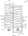
- seed processor 150 has a residue receiving end (or "upstream end”) 152 that is oriented toward or facing cleaning system 13. Seed processor 150 also has a residue discharging end (or "downstream end”) 154 located opposite upstream end 152 and oriented toward or facing distribution system 24. A plurality of roller pairs 160 are arranged in parallel to one another between upstream end 152 and downstream end 154.
- each roller pair 160 includes a first roller 170 and a second roller 180.
- First roller 170 has a cylindrical body 172 and a left hand helical ridge or thread 174 extending around the body. Thread 174 defines a series of crests 176 along the length of first roller 170, with the spacing or "pitch" between adjacent crests being constant. A space or gap 178 is defined between adjacent crests 176.
- second roller 180 has a cylindrical body 182 and a right hand helical ridge or thread 184 extending around the body. Thread 184 defines a series of crests 186 along the length of second roller 180, with the spacing or "pitch" between adjacent crests being constant. A space or gap 188 is defined between adjacent crests 186.
- First roller 170 and second roller 180 of each roller pair 160 are juxtaposed in a mated arrangement.
- thread 174 of first roller 170 is received in gap 188 of second roller 180
- thread 184 of the second roller is received in gap 178 of the first roller.
- Thread 174 defines a shearing surface 177 at its outer most portion that faces an opposing shearing surface 189 on body 182.
- thread 184 defines a shearing surface 187 at its outer most portion that faces an opposing shearing surface 179 on body 172.
- the roller pairs are all arranged with their respective threads mated in this fashion, such that each roller is mated with an adjacent roller on each side, with the exception of the two rollers one each end, as shown in FIG.
- the distance between each crest 176 on first roller 170 and body 182 of second roller 180 is very small, as is the distance between each crest 186 on second roller 180 and body 172 of first roller.
- the space between shearing surfaces 177 and 189, and the space between shearing surfaces 179 and 187 is very narrow.
- the clearance between shearing surface 177 and shearing surface 189 can be between about 0.1 mm to about 0.5 mm, and the clearance between shearing surface 187 and shearing surface 179 can be between about 0.1 mm to about 0.5 mm.
- Each first roller 170 is connected to a drive mechanism 161 that rotates each first roller in a first direction of rotation (e.g. clockwise).
- each second roller 180 is connected to a drive mechanism 162 that rotates each second roller in a second direction of rotation opposite the first direction (e.g. counterclockwise).
- the major diameter 175 of each first roller 170 i.e. the diameter of the circular profile of thread 174 is significantly larger than the minor diameter 173 of the first roller (i.e. the diameter of body 172).
- the major diameter 185 of each second roller 180 i.e. the diameter of the circular profile of thread 184) is significantly larger than the minor diameter 183 of the first roller (i.e. the diameter of body 182).
- This differential in diameter creates a corresponding differential between the turning velocity of the opposing shearing surfaces when the rollers are driven at the same or similar speeds.
- the turning velocity of shearing surfaces 177 and 187 are higher than the turning velocities of shearing surfaces 179 and 189 (along the inner diameters).
- Seed processor 150 further includes a catch plate 190 beneath the roller pairs 160.
- Catch plate 190 is spaced closely to the rollers with very tight clearance.
- the clearance between catch plate 190 and each roller can be between about 0.1 mm to about 0.5 mm.
- Other clearances can also be suitable, and the selection can depend on factors such as, but not limited to, the desired throughput and/or the physical nature of crop residue.
- Catch plate 190 includes a series of concave sections 192, each concave section aligned with a roller immediately above the concave section as shown in FIG. 2 .
- the seed processor receives crop residue material in a top loading fashion, where material is dropped onto the rollers at or near the upstream end.
- the seed processor preferably has one or more guides that direct the flow of crop residue material to areas between adjacent rollers.
- a series of inverted V-shaped baffles or ramps 196 are incrementally arranged above roller pairs 160 and extend in a longitudinal direction between the upstream end 152 and downstream end 154.
- Each baffle 196 has a pair of downwardly sloped surfaces 197 oriented at angles relative to the axis of the corresponding rollers. The downwardly sloping surfaces 197 are oriented toward spaces between adjacent rollers as shown. In this arrangement, adjacent baffles 196 funnel the crop material toward the spaces between adjacent rollers where the threads mate with one another.
- Drive mechanisms 161 and 162 are activated to rotate the first rollers 170 and second rollers 180 in opposite directions of rotation.
- Crop material is fed through threshing system 12 to separate grain from crop residue in any conventional manner. Chaff and grain drops from threshing system 12 and enters cleaning system 13. Chaff that is discharged from cleaning system 13is conveyed to upstream end 152 of seed processor 150, where the material is dropped onto the seed processor by gravity. Crop residue falls by gravity and initially lands on the baffles 196. The inverted V-shape of each baffle directs material to either side of the baffle as the material continues to fall by gravity.
- Adjacent baffles 196 create a funneling effect or chute that directs the falling material toward the narrow areas between each roller pair 160 where the roller threads mate. After the crop residue lands on top of the first and second rollers 170 and 180, the residue is separated based on size, with larger sized material remaining on top of the rollers, and smaller sized material passing into the narrow spaces between threads 174 and 184.
- Material remaining on top of the rollers is carried by the rotating helical threads 174 and 184 toward discharge end 154 of seed processor 150. Larger material that reaches discharge end 154 can then be dropped onto or otherwise conveyed to residue discharge system 24 of combine 10.
- rollers 170 and 180 rotate at the same or substantially similar speeds.
- a number of variables can influence the chosen speed of rotation, including but not limited to the diameter of the rollers 170 and 180.
- rollers 170 and 180 having a diameter of 100 mm can be operated at a speed of between about 100 rpm and about 500 rpm, and more preferably between about 100 rpm and about 200 rpm.
- the resulting differential in turning velocity between the opposing shearing surfaces imparts a shearing effect that destroys the seeds as they pass through rollers 170 and 180.
- the destroyed seeds and other processed residue descend downwardly through rollers 170 and 180 and fall by gravity onto the catch plate 190, where the material is trapped in the small gap between the catch plate and threads 174 and 184.
- Seeds and smaller material trapped on catch plate 190 are conveyed toward discharge end 154 by the rotating threads 144 and 184, similar to the larger material that remains on top of the rollers.
- the destroyed seeds and smaller material that reaches discharge end 154 can then be dropped onto or otherwise conveyed to residue discharge system 24 of combine 10.
- Counter-rotating helical rollers in accordance with the invention provide numerous advantages over other types of processors.
- the helical rollers damage and destroy seeds primarily by shearing. By utilizing shear forces as the primary mechanism for damaging seeds, the rollers only need to be constructed to withstand the relatively small stresses and loads associated with shearing or pinching seeds and smaller material.
- the rollers do not have to crush or break up rocks and other bulky material in the crop residue. Crushing and breaking up larger material requires very rigid components that are capable of exerting and withstanding significant forces for crushing the larger material.
- the sizes and turning velocities of crushing components must also be relatively high, resulting in larger power requirements. In contrast, the power requirement for seed processors in accordance with the invention can be much lower, as crushing of larger material is not required.
- the helical geometry of the rollers combined with the counter-rotation, also provides a dual-conveyance system that efficiently moves residue through the combine.
- the helical threads simultaneously move both large debris and smaller debris from the cleaning system to the discharge system. Throughput of material can be maintained at higher speeds compared to systems that crush material, because larger debris is simply passed through the system over the rollers.
- Seed processors in accordance the invention can include various roller dimensions.
- each roller can have a length of between about 400 mm to about 600 mm, and a major diameter of between about 50 mm to about 150 mm. More specifically, each roller can have a length of about 500 mm and a major diameter of about 100 mm. Other dimensions within or outside the stated ranges can also be used with suitable results in accordance with the invention.
- the thread thickness, pitch and helical angle of each roller can be customized to accommodate different operational requirements.
- Non-helical rollers can also be used in accordance with the invention, such that the rotating threads are substantially normal to the axis of the rollers. Larger and smaller materials that are processed by non-helical rollers can be conveyed by inclining the system and using air, belts, gravity, combinations thereof, and/or other mechanisms to move the material through the processor.
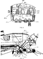
- FIG. 4 shows one such example of an alternative seed processor 250 in accordance with the invention.
- Seed processor 250 receives crop residue that is discharged from a cleaning system, such as cleaning system 13 on combine 10. Before crop residue passes through seed processor 250, the crop residue passes through the thresher system, which separates smaller residual material from larger residual material. The larger material can be conveyed to a chopper and thrown onto a spreader or other residue discharge system on the back of the vehicle. The smaller material from the thresher passes to the cleaning system 13 and then to seed processor 250.
- Seed processor 250 features two non-threaded rollers for damaging and destroying seeds contained in the smaller residue leaving the cleaning system.
- seed processor 250 includes a first or lower roller 270 and second or upper roller 280.
- Lower roller 270 and upper roller 280 are shown mounted to a frame 252.
- Frame 252 can be mounted to the interior of a combine in the same general location that a straw hood would be located.
- Lower roller 270 and upper roller 280 are counter-rotating rollers, i.e. rollers that rotate in opposite directions. With respect to FIG. 4 , lower roller 270 rotates in a clockwise direction 272 with respect to the Figure, and upper roller 280 rotates in a counter-clockwise direction 282 with respect to the Figure, as shown by the respective arrows. Lower roller 270 and upper roller 280 are individually mounted with a small space or gap 251 between them. Gap 251 is sufficiently small to allow seeds and smaller material to contact lower roller 270 and upper roller 280 as they pass through seed processor 250. Lower roller 270 has a lower shearing surface 271, and upper roller 280 has an upper shearing surface 281 separated from the lower shearing surface by gap 251. As will be explained, seeds that pass between lower roller 270 and upper roller 280 are gripped by lower shearing surface 271 and upper shearing surface 281 to impart shear stresses to the seeds and destroy the seeds before they exit the combine.
- Lower roller 270 and upper roller 280 can be hydraulically driven or mechanically driven with a pulley and belt.
- Lower roller 270 is connected to a first gearing 274, and upper roller 280 is connected to a second gearing 284.
- First gearing 274 is configured to transmit torque to lower roller 270 so as to rotate the lower roller and lower shearing surface 271 at a first speed.
- Second gearing 284 is configured to transmit torque to upper roller 280 so as to rotate the upper roller and upper shearing surface 281 at a second speed that is different from the first speed.
- the speed differential between lower shearing surface 271 and upper shearing surface 281 causes shear stresses to develop in the crop flow that destroy the seeds before they exit the combine.
- Lower roller 270 and upper roller 280 can operate at various speeds, depending in part on the type and nature of material passing through the rollers, the desired throughput, and the diameters of the rollers. For example, lower roller 270 can operate at a speed of about 2,000 rpm, and upper roller 280 can operate at a slightly faster speed of about 2,100 rpm, creating a speed differential that imparts shear stresses that destroy seeds in the material.
- a typical speed differential for imparting shear stresses that destroy seeds is between approximately 5% and approximately 20%. However, speed differentials below this range as well as speed differentials above this range can also provide suitable shear stresses to destroy seeds.
- Seed processors in accordance with the invention that utilize rollers can include an adjustment mechanism to account for fluctuations in the size or mass of material passing through rollers.
- An adjustment mechanism can be desirable to reduce the potential for crop material backing up or clogging the seed processor.
- lower roller 270 is a stationary roller that remains in a fixed position relative to frame 252 during operation.
- Upper roller 280 is a displaceable or adjustable roller that can change position relative to frame 252 during operation. The position of upper roller 280 adjusts automatically in response to changes in the size or mass of the crop flow entering between the rollers, so as to prevent material from clogging the seed processor 250.
- An increase in the size or mass of material passing through lower roller 270 and upper roller 280 will exert an outwardly directed force on both rollers, like a wedge.
- Upper roller 280 is displaced or deflected outwardly and away from lower roller 270 in response to this outward force.
- Lower roller 270 remains fixed in position relative to frame 252, as noted earlier.
- Upper roller 280 is displaceable between a home position and a deflected position in response to changes in size or mass of material passing through the rollers.
- upper roller 280 In the home position, upper roller 280 is at a position closest to lower roller 270, such that gap 251 is at a minimum width.
- upper roller 280 In a deflected position, upper roller 280 is moved outwardly and away from the home position, which increases the width of gap 251.
- a biasing mechanism 258 exerts a biasing force on upper roller 280 to urge the upper roller toward the home position.
- biasing mechanism 258 includes a compression spring 259 which is in a relaxed state when upper roller 280 is in the home position.
- Compression spring 259 is compressed under stored energy and remains compressed until the outward force on upper roller 280 is released. Once outward force on upper roller 280 is released, the stored energy in compression spring 259 expands the spring to return the upper roller to the home position.
- Seed processors in accordance with the invention can include one or more flow control mechanisms to prevent too much material from entering the seed processor at one time and possibly choking the system.
- seed processor 250 includes a series of fingers 253 mounted above the flow and just upstream or proximal to lower roller 270 and upper roller 280.
- Fingers 253 can take one of many structural forms, including but not limited to rods, grates, tines or other elongated members. Each finger 253 descends downwardly toward the crop flow and causes the crop material to deflect or converge so that the material is guided toward the space between the lower roller 270 and upper roller 280. As such, fingers 253 channel the crop residue and cause it to merge through the lower roller 270 and upper roller 280.
- Seed processor 250 can also include an optional sieve 255 at the upstream end of the seed processor.
- Sieve 255 separates weed material from chaff, allowing the weed material and any seeds to pass through the sieve and enter lower roller 270 and upper roller 280.
- the chaff is diverted directly to the residue discharge system.
- Sieve 255 reduces the amount of material fed between lower roller 270 and upper roller 280, reducing the amount of material that is processed and increasing throughput.
- seeds in the residue are destroyed by shear forces. Residue that exits the rollers is compressed into a thin flat layer.
- the flat layer of material is conveyed by an adjustable pan 257 that delivers the material to residue discharge system 24 with the aid of gravity.
- seed processors in accordance with the invention can be designed as optional accessories that can be selectively engaged and disengaged.
- seed processors in accordance with the invention can be mounted on a movable mounting assembly that allows the seed processor to be moved into the path of crop residue when seed processing is required, and moved out of the path of crop residue when seed processing is not desired.
- seed processor 250 is mounted on a pivot assembly 261.
- Pivot assembly 261 is configured to permit seed processor 250 to fold downwardly and out of the path between the cleaning system and residue discharge system. Once folded down, seed processor 250 can be locked in the folded position where it remains in a stowed or inoperable condition.
- a top pan 263 can be installed in the place of seed processor 250 to connect the cleaning system with the residue discharge system so that the combine runs without the seed processor.
- seed processor 350 is shown in accordance with another exemplary embodiment.
- seed processors in accordance with the invention can be utilized on various types of combines, including conventional combines and axial combines.
- Seed processor 350 which is installed on a rear section of a combine harvester, such as combine 10, includes a cross conveyor 360 that receives crop residue from a cleaning system. Chaff and smaller materials from cleaning system can drop onto cross conveyor 360 by gravity, or through other channels.
- Cross conveyors in accordance with the invention are configured to move smaller materials from cleaning system to one or both sides of the combine 10 for processing.
- cross conveyors in accordance with the invention can include various mechanisms for moving material, including but not limited to augers and pneumatic systems.
- cross conveyor 360 is in the form of an auger conveyor 362 that extends transversely to the longitudinal axis of combine 10 (i.e. an axis extending from the front of the vehicle to the rear of the vehicle parallel to the direction forward movement).
- Auger conveyor 362 includes a shaft with a first helical thread 364 on one side of the shaft and a second helical thread 366 on the other side of the shaft that appears as a mirror image or reverse configuration of the first helical thread. That is, first helical thread 364 winds in a first direction and angle, and second helical thread 366 winds in a second direction opposite the first direction.
- the first and second helical threads 364, 366 are oriented in opposing directions so that the threads catch smaller material that falls from the cleaning system and carry that material to opposite ends 365 of shaft 364, and toward the outer sides of combine 10, while the auger conveyor rotates.
- processor housing 370 includes a drum 380 rotatably mounted inside a fixed concave wrapper or "concave" 390.
- Drum 380 has an outer surface 382 that includes a plurality of projecting elements 384 projecting radially outwardly from the outer surface.
- Concave 390 has an inner surface 392 that includes a plurality of projecting elements 394 projecting radially inwardly from the inner surface. Projecting elements 394 are incrementally spaced relative to one another on inner surface 392 to form channels or passages 395 therebetween.
- Passages 395 are arranged along inner surface 392 so as to radially and axially align with projecting elements 384 on drum 380 when the drum is mounted inside concave 390.
- the dimensions of passages 395 are adapted to allow projecting elements 394 to pass between projecting elements 384 as drum 380 rotates inside concave 390. As such, projecting elements 384 intermesh with projecting elements 394 as drum 380 rotates relative to concave 390.
- seed processor 350 direct material outwardly toward the sides of combine 10 for processing
- an auger conveyor or other conveying mechanism could receive material from cleaning system 13 and convey the material inwardly toward the center of combine 10 for processing. Processing of material at the center of combine 10 could take place in one or more processor housings similar to processor housings 370. The processed material could then be conveyed from the processor housing(s) to the residue discharge system by a conveyor system.
- the conveyor system could be any type of bulk material handling system, including but not limited to an inclined auger as previously described, pneumatic conveyor, drag chain or bucket elevator.
- Each projecting element 384 has a relatively wide base end 386, a relatively narrow free end 388, and sidewalls 387 that connect the base end to the free end. Sidewalls 387 taper and converge toward one another as the sidewalls extend toward free end 388.
- each projecting element 394 has a relatively wide base end 396, a relatively narrow free end 398, and sidewalls 397 that connect the base end to the free end. Sidewalls 397 taper and converge toward one another as the sidewalls extend toward free end 398.
- each projecting element 384 and 394 has a generally trapezoidal or triangular shaped profile as shown.
- the clearances between projecting elements 384 and projecting elements 394 are very small so as to be less than the diameter of seeds encountered in the crop residue.
- the tight clearances allow the opposing surfaces of the projecting elements to impart shear stresses to seeds passing through seed processor 350 as drum 380 rotates in concave 390.
- a first clearance 372 between opposing sidewalls 387 and 397 can be between about 0.5 mm to about 1.0 mm.
- a second clearance 374 between free ends 388 and inner surface 392 of concave 390 can also be between about 0.5 mm and about 1.0 mm.
- a third clearance 376 between free ends 398 and outer surface 382 of drum 380 can also be between about 0.5 mm and about 1.0 mm.
- each processor housing 370 As drum 380 rotates in the fixed concave 390, seeds are damaged and destroyed by shear forces imparted to the seeds from the opposing surfaces between the drum and concave, and their respective projections.
- material is propelled toward the outside or outward facing end 378 of each processor housing 370 where it exits into an inclined auger 400.
- Each inclined auger 400 receives processed material from each processor housing 370 and conveys the material upwardly and rearwardly to a discharge head or trough 410. Processed seeds and other residue either fall by gravity into the field from discharge trough 410, or fall into residue discharge system 24 for dispersion into the field.
- seed processor 350 can include an adjustment system 450 that allows fine adjustment to clearances between drum 380 and concave 390 so that clearances are precisely controlled. Finer adjustment allows the operator to achieve a better balance between effecting enough shear stresses in the crop material to damage seeds, and providing an acceptable processing rate.
- adjustment system 450 includes a pivoting arrangement between concave 390 and drum 380.
- a pair of plates 452 (only one of which is shown in FIG. 11 ) are welded, bolted or otherwise connected to each side of concave 390.
- Concave 390 and plates 452 are mounted on a pivot hinge 454 that allows the concave and plates to pivot in unison relative to drum 380.
- Adjustment nut 456 extends through a pair of openings 458 in each of plates 452. Adjustment nut 456 is displaceable in a direction 460 along a fine thread adjusting screw 458. Adjusting screw 458 features an external thread 459 that engages an internal thread 457 inside adjustment nut 456. Adjusting screw 458 extends normal to the drum axis and carries adjustment nut 456. One end of adjusting screw 458 is connected to a hub 462, which in turn is connected to an electric motor 464. Electric motor 464 is operable to rotate hub 462 and adjusting screw 458. When adjusting screw 458 rotates, adjustment nut 456 moves axially toward or away from drum 380 in direction 460.
- Thread 459 is configured such that adjustment nut 456 moves a very small distance in response to one revolution of adjusting screw 458, resulting in a very fine pivot motion of plates 452 and concave 390.
- electric motor 464 and adjustment nut 456 are operable to pivot or tilt concave 390 toward drum 380 or away from the drum, depending on the direction of rotation of adjusting screw 458, to finely adjust the clearance between the drum and concave.
- the clearance between drum 380 and concave 390 can be precisely adjusted to correspond to particular seed sizes and the extent of weed infestation. If the weed infestation is low or not a concern, for example, then the clearances can be increased to increase throughput capacity. If weed infestation is high, then the clearances can be decreased to maximize seed damage as material is passed through the seed processor 350. Seed processor 350 can operate at a different throughput rate than cross conveyor 360. The throughput rate of seed processor 350 can be increased to support the high capacity of the machine and also to increase the rate of seed damage.
- seed processor 350 can be equipped with a bypass mechanism 420 that allows the seed processor to be bypassed when seed damage is either not required or not a concern.
- Bypass mechanism 420 shown in FIG. 9 , can include a deflector pan 422 that pivots to a downward position in which the deflector pan covers cross conveyor 360 and cross conveyor trough 361.
- deflector pan 422 covers cross conveyor trough 361, chaff is directly conveyed to residue discharge system 24 and bypasses seed processor 350.
- Deflector pans in accordance with the invention are stationary when covering the cross conveyors. Therefore, it is sometimes desirable to include a movable agitator that ensures that chaff and other material continues to move past the deflector pan. Referring to FIGS.
- a rubber curtain or mat 424 is attached to an oscillating shoe 425 in front of cross conveyor trough 361.
- rubber mat 424 covers the deflector pan and oscillates, creating a moving surface on top of the deflector pan that keeps material moving over the deflector pan and on to the discharge system.
- deflector pan 422 is raised to allow entry of material into cross conveyor 360, rubber mat 424 will hang into the trough opening, but not touch the cross conveyor 360.
- Rollers, drums, concaves, projections and other components that process seeds in accordance with the invention can be constructed of any suitable material that is ordinarily used in the manufacture of combine parts, including but not limited to steel or aluminum.
- components that process seeds in accordance with the invention can be provided with a coating for wear resistance.
- components that process seeds in accordance with the invention can be provided with surface finishes to enhance the processing of crop residue, and more specifically, to enhance the shear effect on seeds passing through the processor.
- surfaces on each component can have a surface roughness adapted to grip individual seeds and impart shear forces.
- surfaces on each component can have a wear coating containing small particles with sharp edges, such as carbide particles or other surface elements.
- rollers in accordance with the invention can have various geometric protuberances that project outwardly from the rollers, such as spikes, teeth, barbs or other projections. Such projections can have a number of geometries including triangular, trapezoidal or other polygonal shapes.
- roller surfaces in accordance with the invention can include various groove configurations, such as surfaces used on processors used for producing shredded silage.
- Seed processors in accordance with the invention can include one or more "pre-processors" that process material prior to entering the seed processor.
- a chopping device can be utilized upstream of the seed processor to reduce the size of materials about to enter the seed processor so that the materials can be processed more easily.
- seed processors in accordance with the invention can include a metal detector or solid object detector to prevent entry of such objects into the seed processor.
- Seed processors in accordance with the invention can also include various types of mechanical separators to prevent larger objects from entering the processor.
- a seed processor can include an oscillating screen 430 laid over an entry trough, such as the entrance of cross conveyor 360 shown in FIG. 10 , to only allow small material like chaff and weed seeds to pass into the seed processor. The screen would convey the other objects directly to the residue distribution system.
Landscapes
- Engineering & Computer Science (AREA)
- Food Science & Technology (AREA)
- Life Sciences & Earth Sciences (AREA)
- Environmental Sciences (AREA)
- Harvesting Machines For Specific Crops (AREA)
- Apparatuses For Bulk Treatment Of Fruits And Vegetables And Apparatuses For Preparing Feeds (AREA)
- Adjustment And Processing Of Grains (AREA)
- Threshing Machine Elements (AREA)
- Pretreatment Of Seeds And Plants (AREA)
Applications Claiming Priority (1)
| Application Number | Priority Date | Filing Date | Title |
|---|---|---|---|
| US15/629,387 US10314232B2 (en) | 2017-06-21 | 2017-06-21 | System and method for destroying seeds in crop residue prior to discharge from agricultural harvester |
Publications (2)
| Publication Number | Publication Date |
|---|---|
| EP3417695A1 true EP3417695A1 (de) | 2018-12-26 |
| EP3417695B1 EP3417695B1 (de) | 2020-10-21 |
Family
ID=62715933
Family Applications (1)
| Application Number | Title | Priority Date | Filing Date |
|---|---|---|---|
| EP18178810.0A Active EP3417695B1 (de) | 2017-06-21 | 2018-06-20 | System zur vernichtung von samen in ernterückständen vor der entladung aus einer landwirtschaftlichen erntemaschine |
Country Status (4)
| Country | Link |
|---|---|
| US (2) | US10314232B2 (de) |
| EP (1) | EP3417695B1 (de) |
| AU (3) | AU2018204474C1 (de) |
| BR (1) | BR102018010600B1 (de) |
Cited By (2)
| Publication number | Priority date | Publication date | Assignee | Title |
|---|---|---|---|---|
| EP4048056A4 (de) * | 2019-10-25 | 2023-11-22 | Seed Terminator Holdings Pty Ltd | Materialbearbeitungsbehälter und zugehöriges materialverarbeitungssystem |
| EP4714247A1 (de) * | 2024-09-20 | 2026-03-25 | CNH Industrial America LLC | Rückstandsbehandlungssystem für mähdrescher |
Families Citing this family (77)
| Publication number | Priority date | Publication date | Assignee | Title |
|---|---|---|---|---|
| CA3094247A1 (en) * | 2018-03-22 | 2019-09-26 | Seed Terminator Holdings PTY LTD | An impact mill and a residue processing system incorporating same |
| US11178818B2 (en) | 2018-10-26 | 2021-11-23 | Deere & Company | Harvesting machine control system with fill level processing based on yield data |
| US11240961B2 (en) | 2018-10-26 | 2022-02-08 | Deere & Company | Controlling a harvesting machine based on a geo-spatial representation indicating where the harvesting machine is likely to reach capacity |
| US11672203B2 (en) | 2018-10-26 | 2023-06-13 | Deere & Company | Predictive map generation and control |
| US11653588B2 (en) | 2018-10-26 | 2023-05-23 | Deere & Company | Yield map generation and control system |
| US11589509B2 (en) | 2018-10-26 | 2023-02-28 | Deere & Company | Predictive machine characteristic map generation and control system |
| US11079725B2 (en) | 2019-04-10 | 2021-08-03 | Deere & Company | Machine control using real-time model |
| US11641800B2 (en) * | 2020-02-06 | 2023-05-09 | Deere & Company | Agricultural harvesting machine with pre-emergence weed detection and mitigation system |
| US11467605B2 (en) | 2019-04-10 | 2022-10-11 | Deere & Company | Zonal machine control |
| US11957072B2 (en) | 2020-02-06 | 2024-04-16 | Deere & Company | Pre-emergence weed detection and mitigation system |
| US12069978B2 (en) | 2018-10-26 | 2024-08-27 | Deere & Company | Predictive environmental characteristic map generation and control system |
| US10986778B2 (en) * | 2018-10-31 | 2021-04-27 | Deere & Company | Weed seed devitalizer control |
| US11206763B2 (en) * | 2018-10-31 | 2021-12-28 | Deere & Company | Weed seed based harvester working member control |
| CA3231538C (en) * | 2019-03-14 | 2025-09-09 | Tritana Intellectual Property Ltd. | Weed seed destruction |
| US11234366B2 (en) | 2019-04-10 | 2022-02-01 | Deere & Company | Image selection for machine control |
| US11510364B2 (en) | 2019-07-19 | 2022-11-29 | Deere & Company | Crop residue based field operation adjustment |
| US11758847B2 (en) | 2019-09-19 | 2023-09-19 | Deere & Company | Residue quality assessment and performance system for a harvester |
| US12329148B2 (en) | 2020-02-06 | 2025-06-17 | Deere & Company | Predictive weed map and material application machine control |
| US12225846B2 (en) | 2020-02-06 | 2025-02-18 | Deere & Company | Machine control using a predictive map |
| US12035648B2 (en) | 2020-02-06 | 2024-07-16 | Deere & Company | Predictive weed map generation and control system |
| DE102021200028A1 (de) * | 2020-02-06 | 2021-08-12 | Deere & Company | Landwirtschaftliche erntemaschine mit vorauflauf-unkrauterkennungs- und -eindämmungssystem |
| US11477940B2 (en) | 2020-03-26 | 2022-10-25 | Deere & Company | Mobile work machine control based on zone parameter modification |
| US12386354B2 (en) | 2020-10-09 | 2025-08-12 | Deere & Company | Predictive power map generation and control system |
| US11825768B2 (en) | 2020-10-09 | 2023-11-28 | Deere & Company | Machine control using a predictive map |
| US12550802B2 (en) | 2020-10-08 | 2026-02-17 | Deere & Company | Predictive machine characteristic map generation and control system |
| US11927459B2 (en) | 2020-10-09 | 2024-03-12 | Deere & Company | Machine control using a predictive map |
| US11844311B2 (en) | 2020-10-09 | 2023-12-19 | Deere & Company | Machine control using a predictive map |
| US11946747B2 (en) | 2020-10-09 | 2024-04-02 | Deere & Company | Crop constituent map generation and control system |
| US11871697B2 (en) | 2020-10-09 | 2024-01-16 | Deere & Company | Crop moisture map generation and control system |
| US11635765B2 (en) | 2020-10-09 | 2023-04-25 | Deere & Company | Crop state map generation and control system |
| US11874669B2 (en) | 2020-10-09 | 2024-01-16 | Deere & Company | Map generation and control system |
| US11727680B2 (en) | 2020-10-09 | 2023-08-15 | Deere & Company | Predictive map generation based on seeding characteristics and control |
| US12422847B2 (en) | 2020-10-09 | 2025-09-23 | Deere & Company | Predictive agricultural model and map generation |
| US11592822B2 (en) | 2020-10-09 | 2023-02-28 | Deere & Company | Machine control using a predictive map |
| US12419220B2 (en) | 2020-10-09 | 2025-09-23 | Deere & Company | Predictive map generation and control system |
| US11864483B2 (en) | 2020-10-09 | 2024-01-09 | Deere & Company | Predictive map generation and control system |
| US11849671B2 (en) | 2020-10-09 | 2023-12-26 | Deere & Company | Crop state map generation and control system |
| US12013245B2 (en) | 2020-10-09 | 2024-06-18 | Deere & Company | Predictive map generation and control system |
| US11845449B2 (en) | 2020-10-09 | 2023-12-19 | Deere & Company | Map generation and control system |
| US11895948B2 (en) | 2020-10-09 | 2024-02-13 | Deere & Company | Predictive map generation and control based on soil properties |
| US11889788B2 (en) | 2020-10-09 | 2024-02-06 | Deere & Company | Predictive biomass map generation and control |
| US11711995B2 (en) | 2020-10-09 | 2023-08-01 | Deere & Company | Machine control using a predictive map |
| US11983009B2 (en) | 2020-10-09 | 2024-05-14 | Deere & Company | Map generation and control system |
| US11849672B2 (en) | 2020-10-09 | 2023-12-26 | Deere & Company | Machine control using a predictive map |
| US11675354B2 (en) | 2020-10-09 | 2023-06-13 | Deere & Company | Machine control using a predictive map |
| US12178158B2 (en) | 2020-10-09 | 2024-12-31 | Deere & Company | Predictive map generation and control system for an agricultural work machine |
| US12069986B2 (en) | 2020-10-09 | 2024-08-27 | Deere & Company | Map generation and control system |
| US11474523B2 (en) | 2020-10-09 | 2022-10-18 | Deere & Company | Machine control using a predictive speed map |
| US11650587B2 (en) | 2020-10-09 | 2023-05-16 | Deere & Company | Predictive power map generation and control system |
| US12250905B2 (en) | 2020-10-09 | 2025-03-18 | Deere & Company | Machine control using a predictive map |
| US11889787B2 (en) | 2020-10-09 | 2024-02-06 | Deere & Company | Predictive speed map generation and control system |
| US12127500B2 (en) | 2021-01-27 | 2024-10-29 | Deere & Company | Machine control using a map with regime zones |
| WO2022236413A1 (en) * | 2021-05-13 | 2022-11-17 | Tritana Intellectual Property Ltd. | Combine harvester with a weed seed destruction device feeding to a straw spreader |
| US12114609B2 (en) | 2021-07-21 | 2024-10-15 | Cnh Industrial America Llc | Integrated weed seed mill and chopper for combine harvester |
| US12010945B2 (en) | 2021-08-31 | 2024-06-18 | Cnh Industrial America Llc | Internal drive system for weed seed mill of combine harvester |
| AU2022350657A1 (en) | 2021-09-22 | 2024-03-07 | Cnh Industrial America Llc | Oscillating chaff pan for weed seed mill of combine harvester |
| US11950528B2 (en) | 2021-09-23 | 2024-04-09 | Cnh Industrial America Llc | Common drive member for weed seed mill of combine harvester |
| US12229886B2 (en) | 2021-10-01 | 2025-02-18 | Deere & Company | Historical crop state model, predictive crop state map generation and control system |
| DE102021128494A1 (de) * | 2021-11-02 | 2023-05-04 | Deere & Company | Dreschkorb für einen Mähdrescher |
| US12310286B2 (en) | 2021-12-14 | 2025-05-27 | Deere & Company | Crop constituent sensing |
| US12302791B2 (en) | 2021-12-20 | 2025-05-20 | Deere & Company | Crop constituents, predictive mapping, and agricultural harvester control |
| US20230200298A1 (en) | 2021-12-29 | 2023-06-29 | Cnh Industrial America Llc | System for detecting a condition indicative of plugging of an agricultural combine |
| US12245549B2 (en) | 2022-01-11 | 2025-03-11 | Deere & Company | Predictive response map generation and control system |
| US12082531B2 (en) | 2022-01-26 | 2024-09-10 | Deere & Company | Systems and methods for predicting material dynamics |
| US12520759B2 (en) | 2022-01-26 | 2026-01-13 | Deere & Company | Systems and methods for predicting material dynamics |
| US12295288B2 (en) | 2022-04-05 | 2025-05-13 | Deere &Company | Predictive machine setting map generation and control system |
| US12298767B2 (en) | 2022-04-08 | 2025-05-13 | Deere & Company | Predictive material consumption map and control |
| US12284934B2 (en) | 2022-04-08 | 2025-04-29 | Deere & Company | Systems and methods for predictive tractive characteristics and control |
| US12058951B2 (en) | 2022-04-08 | 2024-08-13 | Deere & Company | Predictive nutrient map and control |
| US12358493B2 (en) | 2022-04-08 | 2025-07-15 | Deere & Company | Systems and methods for predictive power requirements and control |
| US12582035B2 (en) | 2022-04-08 | 2026-03-24 | Deere & Company | Systems and methods for predictive power requirements and control |
| US12457934B2 (en) | 2023-01-09 | 2025-11-04 | Deere & Company | Residue sensing and cleaning system |
| US12310285B2 (en) | 2023-02-27 | 2025-05-27 | Deere & Company | Agricultural operation evaluation system and method |
| US12550819B2 (en) | 2023-04-12 | 2026-02-17 | Deere & Company | Residue sensor protection on a harvester |
| US20250081888A1 (en) | 2023-09-13 | 2025-03-13 | Cnh Industrial America Llc | Deflector door for accessing a sieve of a combine harvester having a seed mill |
| US20250234810A1 (en) | 2024-01-19 | 2025-07-24 | Cnh Industrial America Llc | Variable speed drive for chaff mill of combine harvester |
| AU2025226864A1 (en) | 2024-09-20 | 2026-04-09 | Cnh Industrial America Llc | Residue management system for combine harvester |
Citations (12)
| Publication number | Priority date | Publication date | Assignee | Title |
|---|---|---|---|---|
| BE539697A (de) * | ||||
| US3448933A (en) * | 1966-10-14 | 1969-06-10 | Melvin C Roy | Apparatus for use with a combine to destroy the germination of weed seeds |
| DE3320045A1 (de) * | 1983-06-03 | 1984-12-06 | Wilhelm 4408 Dülmen Kemming | Verfahren zum zerkleinern von mais, ccm oder feuchtgetreide und maschinen zur durchfuehrung des verfahrens |
| US5059154A (en) * | 1990-10-19 | 1991-10-22 | The Board Of Trustees Of The University Of Arkansas | Grain cleaner and destructor of foreign matter in harvesting crops |
| US6251009B1 (en) * | 1999-08-06 | 2001-06-26 | Deere & Company | Straw chopper housing |
| DE10350123B3 (de) * | 2003-10-28 | 2005-01-05 | Georg-August-Universität Göttingen | Häckselvorrichtung für einen Mähdrescher |
| WO2008010854A1 (en) * | 2006-07-18 | 2008-01-24 | Shaw Waste Solutions, Llc | Infectious waste treatment system and method |
| US20090098266A1 (en) * | 2007-10-10 | 2009-04-16 | Fernando Roberto Paz Briz | Method and apparatus for separating, purifying, promoting interaction and improving combustion |
| US8313362B2 (en) | 2009-04-16 | 2012-11-20 | Cnh America Llc | Agricultural combine with on-board baler and dust suppression capability |
| US8733241B2 (en) | 2012-05-15 | 2014-05-27 | Cnh Industrial Canada, Ltd. | Continuous round baler chambers and conveyor system |
| US20140252141A1 (en) * | 2011-06-30 | 2014-09-11 | Bühler AG | Method and Device for Producing Flour and/or Semolina |
| US9107349B2 (en) | 2012-08-31 | 2015-08-18 | Cnh Industrial America Llc | System and method for controlling the spreading of crop residue expelled from an agricultural combine |
Family Cites Families (23)
| Publication number | Priority date | Publication date | Assignee | Title |
|---|---|---|---|---|
| US2701596A (en) | 1949-08-08 | 1955-02-08 | Albin O Myrold | Rotary disk type straw cutter for combines |
| FR1494992A (fr) | 1966-08-05 | 1967-09-15 | Cablerie De Clichy | Perfectionnements aux dispositifs d'application de rubans autour d'un câble conducteur électrique ou analogue |
| US3631862A (en) * | 1970-06-30 | 1972-01-04 | Sperry Rand Corp | Supporting and adjusting means for agricultural machines such as combine harvesters |
| US3982549A (en) * | 1975-08-28 | 1976-09-28 | International Harvester Company | Helical element rotor-axial flow combine |
| US4375221A (en) * | 1981-06-10 | 1983-03-01 | Sperry Corporation | Adjustable support for concaves |
| DE3540493C1 (en) | 1985-11-15 | 1987-04-23 | Engelbrecht & Lemmerbrock | Combine harvester with screening out of weeds |
| ATE59314T1 (de) * | 1986-03-21 | 1991-01-15 | Tallinsk Polt Inst | Desintegrator. |
| DE3935529A1 (de) * | 1989-10-25 | 1991-05-02 | Kabelmetal Electro Gmbh | Vorrichtung zur stromuebertragung zwischen zwei endstellen |
| US5489239A (en) * | 1994-09-15 | 1996-02-06 | Case Corporation | Rotary combine |
| DE19547355A1 (de) | 1995-12-19 | 1997-07-03 | Geringhoff Carl Gmbh Co Kg | Zerkleinerungsvorrichtung |
| AU771302B2 (en) | 2000-04-20 | 2004-03-18 | Harvestaire Pty Ltd | Harvest residue destruction system |
| CA2470907A1 (en) | 2004-06-15 | 2005-12-15 | Marcel Couture | Device and method for collecting chaff |
| US7322175B2 (en) * | 2005-08-01 | 2008-01-29 | Macdon Industries Inc. | Crop conditioning roller flute shape |
| AR070371A1 (es) | 2008-02-13 | 2010-03-31 | Harrington Raymond Brian | Destruccion de semillas de maleza y semillas de poblaciones voluntarias |
| US8133100B2 (en) * | 2009-12-18 | 2012-03-13 | Agco Corporation | Combine harvester processing system having adjustable concaves on a suspension system |
| US8056311B1 (en) * | 2010-07-23 | 2011-11-15 | Macdon Industries Ltd | Tensioning of the top roll of a crop conditioner |
| DE102011088512B3 (de) | 2011-12-14 | 2013-01-17 | Thomas Nehls | Spreuaufbereitungs- und -verteilvorrichtung |
| DE102012201334B4 (de) | 2012-01-31 | 2023-03-16 | Deere & Company | Feldhäcksler mit Häckselanordnung |
| US8636568B1 (en) * | 2012-07-11 | 2014-01-28 | Cnh America Llc | Combine stepped threshing chamber |
| US9844783B2 (en) * | 2012-07-26 | 2017-12-19 | John Bihn | Grain crushing apparatuses and processes |
| BE1021128B1 (nl) * | 2013-01-30 | 2015-12-18 | Cnh Industrial Belgium Nv | Geleidingsmechanisme van een oogstmachine |
| ES2781095T3 (es) | 2013-02-19 | 2020-08-28 | Grains Res & Dev Corp | Disposición de desvitalización de semillas de maleza |
| CA2991256C (en) * | 2015-07-14 | 2021-12-07 | Dean Mayerle | Weed seed destruction formed as a common unit with straw spreader |
-
2017
- 2017-06-21 US US15/629,387 patent/US10314232B2/en not_active Ceased
-
2018
- 2018-05-24 BR BR102018010600-7A patent/BR102018010600B1/pt active IP Right Grant
- 2018-06-20 EP EP18178810.0A patent/EP3417695B1/de active Active
- 2018-06-20 AU AU2018204474A patent/AU2018204474C1/en active Active
-
2021
- 2021-06-10 US US17/344,454 patent/USRE49494E1/en active Active
-
2022
- 2022-06-29 AU AU2022204619A patent/AU2022204619B2/en active Active
- 2022-09-29 AU AU2022241554A patent/AU2022241554B2/en active Active
Patent Citations (12)
| Publication number | Priority date | Publication date | Assignee | Title |
|---|---|---|---|---|
| BE539697A (de) * | ||||
| US3448933A (en) * | 1966-10-14 | 1969-06-10 | Melvin C Roy | Apparatus for use with a combine to destroy the germination of weed seeds |
| DE3320045A1 (de) * | 1983-06-03 | 1984-12-06 | Wilhelm 4408 Dülmen Kemming | Verfahren zum zerkleinern von mais, ccm oder feuchtgetreide und maschinen zur durchfuehrung des verfahrens |
| US5059154A (en) * | 1990-10-19 | 1991-10-22 | The Board Of Trustees Of The University Of Arkansas | Grain cleaner and destructor of foreign matter in harvesting crops |
| US6251009B1 (en) * | 1999-08-06 | 2001-06-26 | Deere & Company | Straw chopper housing |
| DE10350123B3 (de) * | 2003-10-28 | 2005-01-05 | Georg-August-Universität Göttingen | Häckselvorrichtung für einen Mähdrescher |
| WO2008010854A1 (en) * | 2006-07-18 | 2008-01-24 | Shaw Waste Solutions, Llc | Infectious waste treatment system and method |
| US20090098266A1 (en) * | 2007-10-10 | 2009-04-16 | Fernando Roberto Paz Briz | Method and apparatus for separating, purifying, promoting interaction and improving combustion |
| US8313362B2 (en) | 2009-04-16 | 2012-11-20 | Cnh America Llc | Agricultural combine with on-board baler and dust suppression capability |
| US20140252141A1 (en) * | 2011-06-30 | 2014-09-11 | Bühler AG | Method and Device for Producing Flour and/or Semolina |
| US8733241B2 (en) | 2012-05-15 | 2014-05-27 | Cnh Industrial Canada, Ltd. | Continuous round baler chambers and conveyor system |
| US9107349B2 (en) | 2012-08-31 | 2015-08-18 | Cnh Industrial America Llc | System and method for controlling the spreading of crop residue expelled from an agricultural combine |
Cited By (2)
| Publication number | Priority date | Publication date | Assignee | Title |
|---|---|---|---|---|
| EP4048056A4 (de) * | 2019-10-25 | 2023-11-22 | Seed Terminator Holdings Pty Ltd | Materialbearbeitungsbehälter und zugehöriges materialverarbeitungssystem |
| EP4714247A1 (de) * | 2024-09-20 | 2026-03-25 | CNH Industrial America LLC | Rückstandsbehandlungssystem für mähdrescher |
Also Published As
| Publication number | Publication date |
|---|---|
| US20180368318A1 (en) | 2018-12-27 |
| BR102018010600B1 (pt) | 2023-03-21 |
| AU2018204474C1 (en) | 2022-12-15 |
| USRE49494E1 (en) | 2023-04-18 |
| AU2022241554B2 (en) | 2024-08-01 |
| AU2022204619B2 (en) | 2022-12-08 |
| US10314232B2 (en) | 2019-06-11 |
| AU2022204619A1 (en) | 2022-07-21 |
| AU2018204474A1 (en) | 2019-01-17 |
| AU2022241554A1 (en) | 2022-10-27 |
| AU2018204474B2 (en) | 2022-08-11 |
| BR102018010600A2 (pt) | 2019-01-15 |
| EP3417695B1 (de) | 2020-10-21 |
Similar Documents
| Publication | Publication Date | Title |
|---|---|---|
| AU2022241554B2 (en) | System and method for destroying seeds in crop residue prior to discharge from agricultural harvester | |
| EP1529434B1 (de) | System zum Ausstossen von Ernteresten aus einem Mähdrescher | |
| EP2684443B1 (de) | Gestufte Mähdrescher-Dreschkammer | |
| US3794047A (en) | Crop feeding means for an axial flow combine having side by side threshing units | |
| US3669122A (en) | Axial flow combine with a rotary discharge | |
| JPS62500213A (ja) | 作物収穫機と作物収穫方法 | |
| CN107535179B (zh) | 联合收割机 | |
| EP3613274B1 (de) | Maispflückerreiheneinheit | |
| EP3582605B1 (de) | Konisches rotor-entladungsgehäuse mit verstellbaren schaufeln | |
| US4206581A (en) | Corn harvester | |
| CN112547474B (zh) | 旋转式清粮器 | |
| EP1461991A2 (de) | Austrageinrichtung zum Austragen von Erntegut aus einer Erntemaschine | |
| US11147214B2 (en) | Combine with a pre-thresher | |
| EP3369301A1 (de) | Landwirtschaftliche erntemaschine | |
| DE4209020C3 (de) | Trennvorrichtung | |
| US4291521A (en) | Husk separator for corn harvester | |
| RU2803262C1 (ru) | Молотильно-сепарирующее устройство зерноуборочного комбайна | |
| US20260068821A1 (en) | Sprocket for a feederhouse of a combine harvester | |
| WO2025099442A2 (en) | Improvements in combine harvesters | |
| WO2024011323A1 (en) | Weed seed destruction device with a straw guide surface | |
| EP1495668A2 (de) | Axialtrenneinrichtung |
Legal Events
| Date | Code | Title | Description |
|---|---|---|---|
| PUAI | Public reference made under article 153(3) epc to a published international application that has entered the european phase |
Free format text: ORIGINAL CODE: 0009012 |
|
| STAA | Information on the status of an ep patent application or granted ep patent |
Free format text: STATUS: THE APPLICATION HAS BEEN PUBLISHED |
|
| AK | Designated contracting states |
Kind code of ref document: A1 Designated state(s): AL AT BE BG CH CY CZ DE DK EE ES FI FR GB GR HR HU IE IS IT LI LT LU LV MC MK MT NL NO PL PT RO RS SE SI SK SM TR |
|
| AX | Request for extension of the european patent |
Extension state: BA ME |
|
| STAA | Information on the status of an ep patent application or granted ep patent |
Free format text: STATUS: REQUEST FOR EXAMINATION WAS MADE |
|
| 17P | Request for examination filed |
Effective date: 20190626 |
|
| RBV | Designated contracting states (corrected) |
Designated state(s): AL AT BE BG CH CY CZ DE DK EE ES FI FR GB GR HR HU IE IS IT LI LT LU LV MC MK MT NL NO PL PT RO RS SE SI SK SM TR |
|
| STAA | Information on the status of an ep patent application or granted ep patent |
Free format text: STATUS: EXAMINATION IS IN PROGRESS |
|
| 17Q | First examination report despatched |
Effective date: 20190820 |
|
| GRAP | Despatch of communication of intention to grant a patent |
Free format text: ORIGINAL CODE: EPIDOSNIGR1 |
|
| STAA | Information on the status of an ep patent application or granted ep patent |
Free format text: STATUS: GRANT OF PATENT IS INTENDED |
|
| INTG | Intention to grant announced |
Effective date: 20200514 |
|
| GRAS | Grant fee paid |
Free format text: ORIGINAL CODE: EPIDOSNIGR3 |
|
| GRAA | (expected) grant |
Free format text: ORIGINAL CODE: 0009210 |
|
| STAA | Information on the status of an ep patent application or granted ep patent |
Free format text: STATUS: THE PATENT HAS BEEN GRANTED |
|
| AK | Designated contracting states |
Kind code of ref document: B1 Designated state(s): AL AT BE BG CH CY CZ DE DK EE ES FI FR GB GR HR HU IE IS IT LI LT LU LV MC MK MT NL NO PL PT RO RS SE SI SK SM TR |
|
| REG | Reference to a national code |
Ref country code: GB Ref legal event code: FG4D |
|
| REG | Reference to a national code |
Ref country code: CH Ref legal event code: EP |
|
| REG | Reference to a national code |
Ref country code: DE Ref legal event code: R096 Ref document number: 602018008841 Country of ref document: DE |
|
| REG | Reference to a national code |
Ref country code: IE Ref legal event code: FG4D |
|
| REG | Reference to a national code |
Ref country code: AT Ref legal event code: REF Ref document number: 1324869 Country of ref document: AT Kind code of ref document: T Effective date: 20201115 |
|
| REG | Reference to a national code |
Ref country code: AT Ref legal event code: MK05 Ref document number: 1324869 Country of ref document: AT Kind code of ref document: T Effective date: 20201021 |
|
| REG | Reference to a national code |
Ref country code: NL Ref legal event code: MP Effective date: 20201021 |
|
| PG25 | Lapsed in a contracting state [announced via postgrant information from national office to epo] |
Ref country code: NO Free format text: LAPSE BECAUSE OF FAILURE TO SUBMIT A TRANSLATION OF THE DESCRIPTION OR TO PAY THE FEE WITHIN THE PRESCRIBED TIME-LIMIT Effective date: 20210121 Ref country code: GR Free format text: LAPSE BECAUSE OF FAILURE TO SUBMIT A TRANSLATION OF THE DESCRIPTION OR TO PAY THE FEE WITHIN THE PRESCRIBED TIME-LIMIT Effective date: 20210122 Ref country code: PT Free format text: LAPSE BECAUSE OF FAILURE TO SUBMIT A TRANSLATION OF THE DESCRIPTION OR TO PAY THE FEE WITHIN THE PRESCRIBED TIME-LIMIT Effective date: 20210222 Ref country code: RS Free format text: LAPSE BECAUSE OF FAILURE TO SUBMIT A TRANSLATION OF THE DESCRIPTION OR TO PAY THE FEE WITHIN THE PRESCRIBED TIME-LIMIT Effective date: 20201021 Ref country code: FI Free format text: LAPSE BECAUSE OF FAILURE TO SUBMIT A TRANSLATION OF THE DESCRIPTION OR TO PAY THE FEE WITHIN THE PRESCRIBED TIME-LIMIT Effective date: 20201021 |
|
| REG | Reference to a national code |
Ref country code: LT Ref legal event code: MG4D |
|
| PG25 | Lapsed in a contracting state [announced via postgrant information from national office to epo] |
Ref country code: BG Free format text: LAPSE BECAUSE OF FAILURE TO SUBMIT A TRANSLATION OF THE DESCRIPTION OR TO PAY THE FEE WITHIN THE PRESCRIBED TIME-LIMIT Effective date: 20210121 Ref country code: IS Free format text: LAPSE BECAUSE OF FAILURE TO SUBMIT A TRANSLATION OF THE DESCRIPTION OR TO PAY THE FEE WITHIN THE PRESCRIBED TIME-LIMIT Effective date: 20210221 Ref country code: PL Free format text: LAPSE BECAUSE OF FAILURE TO SUBMIT A TRANSLATION OF THE DESCRIPTION OR TO PAY THE FEE WITHIN THE PRESCRIBED TIME-LIMIT Effective date: 20201021 Ref country code: LV Free format text: LAPSE BECAUSE OF FAILURE TO SUBMIT A TRANSLATION OF THE DESCRIPTION OR TO PAY THE FEE WITHIN THE PRESCRIBED TIME-LIMIT Effective date: 20201021 Ref country code: SE Free format text: LAPSE BECAUSE OF FAILURE TO SUBMIT A TRANSLATION OF THE DESCRIPTION OR TO PAY THE FEE WITHIN THE PRESCRIBED TIME-LIMIT Effective date: 20201021 Ref country code: ES Free format text: LAPSE BECAUSE OF FAILURE TO SUBMIT A TRANSLATION OF THE DESCRIPTION OR TO PAY THE FEE WITHIN THE PRESCRIBED TIME-LIMIT Effective date: 20201021 Ref country code: AT Free format text: LAPSE BECAUSE OF FAILURE TO SUBMIT A TRANSLATION OF THE DESCRIPTION OR TO PAY THE FEE WITHIN THE PRESCRIBED TIME-LIMIT Effective date: 20201021 |
|
| PG25 | Lapsed in a contracting state [announced via postgrant information from national office to epo] |
Ref country code: NL Free format text: LAPSE BECAUSE OF FAILURE TO SUBMIT A TRANSLATION OF THE DESCRIPTION OR TO PAY THE FEE WITHIN THE PRESCRIBED TIME-LIMIT Effective date: 20201021 Ref country code: HR Free format text: LAPSE BECAUSE OF FAILURE TO SUBMIT A TRANSLATION OF THE DESCRIPTION OR TO PAY THE FEE WITHIN THE PRESCRIBED TIME-LIMIT Effective date: 20201021 |
|
| REG | Reference to a national code |
Ref country code: DE Ref legal event code: R097 Ref document number: 602018008841 Country of ref document: DE |
|
| PG25 | Lapsed in a contracting state [announced via postgrant information from national office to epo] |
Ref country code: EE Free format text: LAPSE BECAUSE OF FAILURE TO SUBMIT A TRANSLATION OF THE DESCRIPTION OR TO PAY THE FEE WITHIN THE PRESCRIBED TIME-LIMIT Effective date: 20201021 Ref country code: CZ Free format text: LAPSE BECAUSE OF FAILURE TO SUBMIT A TRANSLATION OF THE DESCRIPTION OR TO PAY THE FEE WITHIN THE PRESCRIBED TIME-LIMIT Effective date: 20201021 Ref country code: SM Free format text: LAPSE BECAUSE OF FAILURE TO SUBMIT A TRANSLATION OF THE DESCRIPTION OR TO PAY THE FEE WITHIN THE PRESCRIBED TIME-LIMIT Effective date: 20201021 Ref country code: LT Free format text: LAPSE BECAUSE OF FAILURE TO SUBMIT A TRANSLATION OF THE DESCRIPTION OR TO PAY THE FEE WITHIN THE PRESCRIBED TIME-LIMIT Effective date: 20201021 Ref country code: SK Free format text: LAPSE BECAUSE OF FAILURE TO SUBMIT A TRANSLATION OF THE DESCRIPTION OR TO PAY THE FEE WITHIN THE PRESCRIBED TIME-LIMIT Effective date: 20201021 Ref country code: RO Free format text: LAPSE BECAUSE OF FAILURE TO SUBMIT A TRANSLATION OF THE DESCRIPTION OR TO PAY THE FEE WITHIN THE PRESCRIBED TIME-LIMIT Effective date: 20201021 |
|
| PLBE | No opposition filed within time limit |
Free format text: ORIGINAL CODE: 0009261 |
|
| STAA | Information on the status of an ep patent application or granted ep patent |
Free format text: STATUS: NO OPPOSITION FILED WITHIN TIME LIMIT |
|
| PG25 | Lapsed in a contracting state [announced via postgrant information from national office to epo] |
Ref country code: DK Free format text: LAPSE BECAUSE OF FAILURE TO SUBMIT A TRANSLATION OF THE DESCRIPTION OR TO PAY THE FEE WITHIN THE PRESCRIBED TIME-LIMIT Effective date: 20201021 |
|
| 26N | No opposition filed |
Effective date: 20210722 |
|
| PG25 | Lapsed in a contracting state [announced via postgrant information from national office to epo] |
Ref country code: AL Free format text: LAPSE BECAUSE OF FAILURE TO SUBMIT A TRANSLATION OF THE DESCRIPTION OR TO PAY THE FEE WITHIN THE PRESCRIBED TIME-LIMIT Effective date: 20201021 |
|
| PG25 | Lapsed in a contracting state [announced via postgrant information from national office to epo] |
Ref country code: SI Free format text: LAPSE BECAUSE OF FAILURE TO SUBMIT A TRANSLATION OF THE DESCRIPTION OR TO PAY THE FEE WITHIN THE PRESCRIBED TIME-LIMIT Effective date: 20201021 |
|
| PG25 | Lapsed in a contracting state [announced via postgrant information from national office to epo] |
Ref country code: MC Free format text: LAPSE BECAUSE OF FAILURE TO SUBMIT A TRANSLATION OF THE DESCRIPTION OR TO PAY THE FEE WITHIN THE PRESCRIBED TIME-LIMIT Effective date: 20201021 |
|
| REG | Reference to a national code |
Ref country code: CH Ref legal event code: PL |
|
| REG | Reference to a national code |
Ref country code: BE Ref legal event code: MM Effective date: 20210630 |
|
| PG25 | Lapsed in a contracting state [announced via postgrant information from national office to epo] |
Ref country code: LU Free format text: LAPSE BECAUSE OF NON-PAYMENT OF DUE FEES Effective date: 20210620 |
|
| PG25 | Lapsed in a contracting state [announced via postgrant information from national office to epo] |
Ref country code: LI Free format text: LAPSE BECAUSE OF NON-PAYMENT OF DUE FEES Effective date: 20210630 Ref country code: IE Free format text: LAPSE BECAUSE OF NON-PAYMENT OF DUE FEES Effective date: 20210620 Ref country code: CH Free format text: LAPSE BECAUSE OF NON-PAYMENT OF DUE FEES Effective date: 20210630 |
|
| PG25 | Lapsed in a contracting state [announced via postgrant information from national office to epo] |
Ref country code: IS Free format text: LAPSE BECAUSE OF FAILURE TO SUBMIT A TRANSLATION OF THE DESCRIPTION OR TO PAY THE FEE WITHIN THE PRESCRIBED TIME-LIMIT Effective date: 20210221 |
|
| PG25 | Lapsed in a contracting state [announced via postgrant information from national office to epo] |
Ref country code: BE Free format text: LAPSE BECAUSE OF NON-PAYMENT OF DUE FEES Effective date: 20210630 |
|
| PG25 | Lapsed in a contracting state [announced via postgrant information from national office to epo] |
Ref country code: CY Free format text: LAPSE BECAUSE OF FAILURE TO SUBMIT A TRANSLATION OF THE DESCRIPTION OR TO PAY THE FEE WITHIN THE PRESCRIBED TIME-LIMIT Effective date: 20201021 |
|
| PG25 | Lapsed in a contracting state [announced via postgrant information from national office to epo] |
Ref country code: HU Free format text: LAPSE BECAUSE OF FAILURE TO SUBMIT A TRANSLATION OF THE DESCRIPTION OR TO PAY THE FEE WITHIN THE PRESCRIBED TIME-LIMIT; INVALID AB INITIO Effective date: 20180620 |
|
| PG25 | Lapsed in a contracting state [announced via postgrant information from national office to epo] |
Ref country code: MK Free format text: LAPSE BECAUSE OF FAILURE TO SUBMIT A TRANSLATION OF THE DESCRIPTION OR TO PAY THE FEE WITHIN THE PRESCRIBED TIME-LIMIT Effective date: 20201021 |
|
| PG25 | Lapsed in a contracting state [announced via postgrant information from national office to epo] |
Ref country code: TR Free format text: LAPSE BECAUSE OF FAILURE TO SUBMIT A TRANSLATION OF THE DESCRIPTION OR TO PAY THE FEE WITHIN THE PRESCRIBED TIME-LIMIT Effective date: 20201021 |
|
| PG25 | Lapsed in a contracting state [announced via postgrant information from national office to epo] |
Ref country code: MT Free format text: LAPSE BECAUSE OF FAILURE TO SUBMIT A TRANSLATION OF THE DESCRIPTION OR TO PAY THE FEE WITHIN THE PRESCRIBED TIME-LIMIT Effective date: 20201021 |
|
| PGFP | Annual fee paid to national office [announced via postgrant information from national office to epo] |
Ref country code: DE Payment date: 20250626 Year of fee payment: 8 |
|
| PGFP | Annual fee paid to national office [announced via postgrant information from national office to epo] |
Ref country code: GB Payment date: 20250618 Year of fee payment: 8 |
|
| PGFP | Annual fee paid to national office [announced via postgrant information from national office to epo] |
Ref country code: FR Payment date: 20250624 Year of fee payment: 8 |
|
| PGFP | Annual fee paid to national office [announced via postgrant information from national office to epo] |
Ref country code: IT Payment date: 20250623 Year of fee payment: 8 |