EP3417735A1 - Armbandverschluss, der eine reguliervorrichtung der länge des armbands umfasst - Google Patents
Armbandverschluss, der eine reguliervorrichtung der länge des armbands umfasst Download PDFInfo
- Publication number
- EP3417735A1 EP3417735A1 EP17177222.1A EP17177222A EP3417735A1 EP 3417735 A1 EP3417735 A1 EP 3417735A1 EP 17177222 A EP17177222 A EP 17177222A EP 3417735 A1 EP3417735 A1 EP 3417735A1
- Authority
- EP
- European Patent Office
- Prior art keywords
- clasp
- blade
- bracelet
- length
- locking mechanism
- Prior art date
- Legal status (The legal status is an assumption and is not a legal conclusion. Google has not performed a legal analysis and makes no representation as to the accuracy of the status listed.)
- Withdrawn
Links
Images



Classifications
-
- A—HUMAN NECESSITIES
- A44—HABERDASHERY; JEWELLERY
- A44C—PERSONAL ADORNMENTS, e.g. JEWELLERY; COINS
- A44C5/00—Bracelets; Wrist-watch straps; Fastenings for bracelets or wrist-watch straps
- A44C5/18—Fasteners for straps, chains or the like
- A44C5/22—Fasteners for straps, chains or the like for closed straps
- A44C5/24—Fasteners for straps, chains or the like for closed straps with folding devices
- A44C5/246—Fasteners for straps, chains or the like for closed straps with folding devices having size adjusting means
Definitions
- the present invention relates to the field of bracelets, especially for watches. It relates to a bracelet clasp for adjusting the length of the bracelet.
- the invention also relates to a length adjustment device and a wristwatch having the clasp and / or the length adjustment device.
- a wristwatch clasp generally comprises two fasteners for attaching the free ends of the wristband, and a locking or closing mechanism for locking the two fasteners, and thus the free ends of the wristband, in a stable position of closure. or lock. This position is also the service position, as it allows the wristwatch to be worn on the wrist.
- clasps for example the buckle or buckle clasp fasteners, whose aesthetic is well appreciated.
- the clasps and bracelets for wristwatches generally include means for adjusting the length of the wristband.
- the free end of one of the two strands of the bracelet comprises a series of holes distributed in the longitudinal direction of the bracelet.
- the free end of the other strand of the bracelet is provided with a connecting device, for example a pin buckle, to join the two strands by inserting the barb in the hole corresponding to the desired length.
- the length of the bracelet is adjusted by removing or adding a link in one or both strands of the bracelet.
- the size of the wrist varies considerably from one wearer to another.
- the size of a wearer's wrist can vary with changes in temperature.
- One wearer can therefore regularly wish to finely adjust the length of the bracelet to be perfectly comfortable.
- the state of the art knows clasps for wristwatches that allow a fine adjustment of the length of the bracelet. This is a mechanism arranged to allow a modification of the circumference defined by the case of the watch, the bracelet, and the clasp, when the clasp is closed, in order to adapt this circumference to the size of the wrist of an individual wearer. This modification takes place on a scale smaller than that defined by the spacing of the holes in a strand of leather bracelet or by the links of a metal bracelet, for example. Fine tuning is desirable to accurately fit the aforementioned circumference to the wrist of each wearer.
- the fine adjustment device of a bracelet clasp comprises a movable part arranged on a part of the clasp and carrying one of the two fasteners, the other fastener being attached to another part of the clasp.
- the fine adjustment can be made by moving the moving part relative to the whole clasp, and blocking it to the position corresponding to the desired strap length.
- the fine adjustment device includes a notching or toothing, which defines the discrete positions of length of the fine adjustment. The notching may also be part of the device for locking the moving part in a position of desired length.
- the document CH 704 335 discloses a clasp with folding clasp, wherein a fastener is attached to a carriage arranged to slide in a housing arranged on a blade clasp.
- the clasp comprises a pull tab arranged to cooperate with the carriage and capable of occupying two axial positions so that the carriage is locked and unlocked when the pull tab is respectively in one and the other of the two axial positions.
- a disadvantage of this mechanism is the fact that at least one of the two opposite pushers of the pull tab is projecting relative to the side walls of the clasp blade. The protruding pusher is likely to cling to an external object, for example a garment.
- the bracelet length may be adjustable independently of the closed or open condition of the clasp.
- an object of the present invention is to reduce the thickness, i.e. the extension of the clasp in a radial direction relative to the wrist axis of a wearer.
- Another object of the invention is to reduce the weight of the clasp, for example to reduce the amount of metal used in the manufacture and to make the clasp easier to wear.
- the fine adjustment device is arranged in a yoke or an upper cover, which contributes to the increase in thickness and the overall size of the clasp.
- the movable portion is arranged at one end of a clasp blade so as to extend beyond the end of the blade when the wristband is extended. In this case, the moving part becomes visible as an extension of the clasp.
- An object of the invention is to provide a clasp to adjust the length without this changing the appearance of the clasp from the outside.
- a clasp whose adjustment mechanism remains discreet and fits into the general shape of the clasp may be desirable.
- an objective is to avoid the presence of notches visible from the outside or longitudinal openings arranged along a side wall of a clevis clasp folding clasp.
- An object of the present invention is to provide a clasp for activating the length adjustment when the clasp is closed, and this preferably without a dedicated and separate actuating member, such as a pusher, a zipper or another slide is visible from the outside when the clasp is closed.
- the present invention relates to a clasp for bracelets of the type comprising first and second free ends, the clasp having first and second strap fasteners to be respectively secured to said first and second free ends of the bracelet.
- the present invention relates to a clasp with a folding clasp for a bracelet allowing adjustment of the bracelet length, said clasp having at least two blades articulated relative to each other.
- the present invention relates to a clasp comprising: a first blade and at least a second blade, articulated with respect to each other, the second blade having two side rails; a first fastener connected to the first blade and intended to be secured to a first free end of the bracelet; a second fixing member intended to be secured to a second free end of the bracelet; a locking mechanism arranged to immobilize said first and second blades in the closed position of the clasp when said first and second blades are brought together and folded towards each other; a strap length adjusting device comprising: a movable portion to which said first fastener is attached, said movable portion being arranged to be movable longitudinally with respect to the longitudinal direction of the strap to effect a length adjustment ; and a blocking device arranged to block the displacement of the movable part in at least one direction of longitudinal displacement.
- the subject of the present invention is a clasp with a deploying buckle for a bracelet enabling the length of the bracelet to be adjusted, said clasp comprising: a first blade and a second blade, articulated with respect to one another, the second blade having two side members, a first fastener connected to the first blade and intended to be secured to a first free end of the bracelet; a second fastener, intended to be secured to a second free end of the bracelet; a locking mechanism for holding said first and second blades in the hard clasp closed position when said blades are brought together and folded over each other, said locking mechanism including a manipulator adapted to be activated by a user to unlock the latch; locking mechanism and to open the clasp; a wrist length adjustment device comprising: a movable part to which said first fastener is attached, said movable part being arranged so as to be able to moving longitudinally relative to the longitudinal direction of the bracelet during the adjustment of the length, a locking device arranged to block the displacement of the movable part in at least one direction
- the subject of the present invention is a clasp with a folding clasp for a bracelet enabling the length of a bracelet to be adjusted, said clasp comprising at least two blades articulated with respect to each other, characterized in that at least one of said blades comprises a part comprising a non-metallic material or the entire blade comprises a non-metallic material.
- the present invention relates to a clasp, in particular a clasp for a bracelet.
- the invention relates to a clasp for a timepiece bracelet, preferably for a wristwatch.
- the bracelet can be of any type, such as for example flexible plastic material, leather, or comprising an assembly of links, metal for example.
- the bracelet consists of two longitudinal portions of the bracelet, respectively in the form of first and second strands (not shown), and each of the strands is such that one of its ends is connected to the watch case while that the other is intended to be attached to a fastener of the clasp.
- the end of one of the two strands has a series of holes, and the length is roughly adjusted by choosing the hole in which the pin is inserted.
- the expressions "direction of the length of the bracelet” or “longitudinal direction of the bracelet” are used to designate an axis which is that of the two bracelet strands, assuming that the bracelet is disposed flat and detached from a watch.
- the "direction of the length of the bracelet” designates the line which follows the periphery of the bracelet.
- the strap length adjusted by fine adjustment using the clasp adjusting device according to the invention is in the direction of the length of the bracelet.
- an axis connecting the digits 6 and 12 of the dial generally follows the direction of the wristband length in accordance with the present definition.
- the clasp shown in the figures is substantially symmetrical and therefore comprises a plane which would constitute if the clasp is perfectly symmetrical.
- this plane which extends in the direction of the length of the bracelet and the clasp is considered as "plane of symmetry", even if the symmetry of the clasp is not perfect, for example due to the positioning of the device length adjustment and its locking mechanism.
- orthogonal refers to an axis that is perpendicular to the "direction of the length of the bracelet" and perpendicular to the plane of symmetry of the clasp.
- an axis connecting the numerals 3 and 9 of the dial has an "orthogonal" direction in accordance with this definition.
- a “radial” axis is an axis that is radial to the axis of the wrist or forearm of a wristwatch wearer.
- the radial axis extends in the plane of symmetry or in a plane parallel to the plane of symmetry.
- the "radial" axis is a substantially “vertical” axis, and the two terms are used interchangeably in the present specification.
- the clasp of the invention is a clasp of the unfolding type, a folding clasp or folding clasp.
- This type of clasp is known, for example, from patent documents EP 0913106 , CH700230 , EP2452583 , EP2361523 and CH704335 .
- the clasp has at least two longitudinal clasp segments. In the present description, these longitudinal segments are also called “the blades" of the clasp.
- a clasp comprises two or three longitudinal segments.
- the clasps shown in the figures are clasps with two blades 1, 2. Of course, it would be quite possible to achieve the clasp of the invention with a folding clasp with three blades or with a clasp type pin buckle only.
- the present invention Also considering the clasps that combine the features of a clasp with a folding clasp with a known wrist strap fastener of the tongue buckle.
- a buckle-type clasp in the absence of a folding clasp corresponds to one embodiment of the invention.
- the fine adjustment device of the length of the bracelet according to the invention can be adapted to any type of clasp and is not limited to a particular type of clasp.
- the clasp shown in the figures comprises a first blade 1 and a second blade 2, articulated with respect to one another at a first end.
- the blades 1, 2 are brought together and folded over one another as shown in FIGS. Figures 1, 2, 3B , 11A, 11B .
- the blades 1, 2 are elongated in the longitudinal direction of the bracelet and slightly curved to better fit the shape of the wrist of a wearer.
- the first blade 1 comprises a lower surface 44 ( figure 2 ), intended to face the wrist of the wearer, and an upper surface 21 ( figure 4 ).
- the clasp of the invention comprises a locking mechanism 3 for locking the clasp in the closed position, and unlocking the clasp to move to the open position ( Figures 3A , 4 , 5 , 6A, 6B ) to remove the watch from the wrist.
- Locking means for clasps with folding clasp are known per se.
- the locking mechanism is based on the presence of a latching mechanism, for example formed by extra thicknesses and possibly by recesses, respectively, on the first and second blades.
- a latching mechanism for example formed by extra thicknesses and possibly by recesses, respectively, on the first and second blades.
- a user acts directly on a blade to exert the force necessary to separate the blades or to lock them by fitting, for example.
- the disadvantage of this mechanism is that the wear can make the snap less effective. On the other hand, there is always the risk of accidental opening with this type of closure.
- the clasp of the invention comprises a locking mechanism comprising a manipulator arranged so that an activation of this organ is needed to open the clasp.
- the advantage of this type of mechanism is that accidental opening is excluded.
- the mechanical principle of the locking mechanism 3 of the clasp shown in the figures is similar to that disclosed in the European patent EP0913106B .
- the locking mechanism 3 preferably comprises two lateral manipulation members, a first manipulation member 7 and a second manipulation member 7 '.
- a carrier simultaneously activates the two members 7, 7 '.
- These handling members 7, 7 ' are projecting on each side of the frame 20, in which they are guided and / or housed.
- This frame is preferably arranged at the second end of the first blade 1.
- a clevis a loop as shown in FIG. figure 14
- a lid as shown in the patent EP0913106B to engage the pushers.
- the second fastener not shown, is preferably attached to the frame 20. It may be a spring bar held, for example, between two side walls of the frame or the yoke.
- a hole 45 is visible on the inner face of a side wall of the frame 20, for housing the spring bar together with a corresponding hole arranged on the opposite wall (non-visible).
- the frame 20 of the clasp shown in the figures comprises a recess 46, intended to insert the logo of the manufacturer, for example.
- Each of the handling members 7, 7 ' is connected to one of the two side rails, 14, 14' of the second blade 2.
- the connection (not visible) between the longitudinal members and their respective handling members is located at the second end of the second blade, in the frame 20.
- the two longitudinal members 14, 14 ' are two separate pieces, secured to the articulation of the second blade, towards the first end.
- the two longitudinal members 14, 14 ' are rigidly connected to a common base, generally close to the first end, but they have free ends, which can move relative to each other because of the flexibility of the side members .
- the frame 20 further comprises return means, for example a spring, which urge the handling members 7, 7 'and the side members 14, 14' to the locking position, generally the outer lateral positions of the longitudinal members.
- the return means are not visible in the drawings because they are integrated in the frame 20. The return means are thus arranged to hold the members 7, 7 'in position remote relative to each other .
- the handling members 7, 7 ' are in the form of pushers 7, 7'. Holding the pushers 7, 7 'between the thumb and forefinger and pressing, a carrier performs a rimpedement pushers and side rails 14, 14'.
- the locking mechanism 3 comprises at least two attachment members or complementary attachment members 22, 23, a first form of stop 22 disposed on the first blade 1 and a second form of stop 23 disposed on the second blade 2, said stop shapes 22, 23 being arranged to lock the clasp in the closed position when the stop forms 22, 23 are engaged.
- the first stop form 23 is disposed on the spar 14 and the latter is arranged to act on the actuating member 9 when the clasp is closed and when the manipulation member 7 is activated by a user, as will be described below.
- Each spar 14, 14 ' has, on its outer side, a projecting hook-shaped member 23 ( figures 4 , 6A ).
- a recess or a corresponding stop surface 22 ( Figures 4, 5 ) is formed in the inner side of each spar 15, 15 'of the first blade 1, to receive the hook 23 when the second blade 2 is completely folded on the first blade 1.
- the hooks 23 have rounded shapes below and retention surfaces flattened extending in a plane perpendicular to the plane of clasp symmetry.
- the surfaces of the recesses 22 in contact with the retention surfaces of the hook 23 are also flattened and perpendicular to the clasp symmetry plane.
- the hooks 23 provide a positive engagement automatic locking, when the second blade 2 is pressed to the first blade 1, even if the pushers 7, 7 'are not depressed. An accidental opening of the clasp is prevented thanks to the complementary flat surfaces, as long as the longitudinal members 14, 14 'of the second blade 2 have not been brought closer together by activating the pushers 7, 7'.
- the longitudinal members 14, 14 'of the second blade 2 are not inserted between the sides of the longitudinal members 15, 15' of the first blade 1.
- the longitudinal members 14, 14 ' are placed at the at least partially above the longitudinal members 15, 15 'of the first blade when the clasp is closed.
- Each of the hooks 23 is arranged laterally on a bulge 24 located on the underside of the spar 14, so that the hook is at a level lowered with respect to the general plane of the spar 14 ( Figure 6A ).
- the first blade 1 comprises, at its second end, an extension forming a frame 18 provided for receiving and / or guiding the end of a bracelet strand.
- This frame has two lateral extensions 28 connected at their ends by a transverse plate 29 ( figures 4 and 8 ).
- the lateral extensions 28 comprise a structure 31 in elevation with respect to the upper surface of the first blade.
- the surfaces of the recess 22 are arranged on the inner face of the structure 31 in elevation, so as to be disposed above the general plane of the first blade.
- the bearing surfaces of the hooks 23 are in the same plane as the lower surfaces of the longitudinal members 14, 14 '.
- the bearing surfaces in the recesses 23 are in the same plane as the upper surfaces 21 of the first blade 1.
- the present invention also covers a variant of the locking mechanism 4, according to which the side rails 14, 14 'are arranged so as to move away or to deviate during the activation of the handling member 7, 7' , in order to unlock the locking mechanism.
- one or both of the manipulation members 7, 7 ' are arranged in a manner to be pulled, instead of being driven in, to allow a displacement of the longitudinal members 14, 14 'and thus the unlocking of the locking mechanism.
- the manipulation member (s) is / are then preferably made in the form of a pull-tab rather than a pair of push-buttons. In this case, it may also be a displacement of spacing or approximation of the rails 14, 14 'generating the unlocking.
- biasing means such as a spring, is preferred in order to urge the clasp in the locked position in the absence of activation of the manipulation member 7, 7 '.
- the parts containing the rails 14, 14 'and the handling members 7, 7' intersect inside the frame 20, so that each beam is connected to the frame. manipulator on the opposite lateral side ( figure 13 ).
- the spar 14 is preferably connected to the manipulation member 7 ', and the spar 14' to the member 7.
- the manipulation member and the corresponding spar are preferably made of a room too.
- the handling members 7, 7 ' can be made in the form of pushers, and the activation of these handling members can cause spacing of the rails 14, 14'.
- the clasp of the invention comprises a device for adjusting the length 4 of the bracelet. It is preferably a device for fine adjustment of the length.
- adjustment of the length or “fine adjustment of the length” is meant a device for adjusting the circumference defined by the case of a watch, the two bracelet strands and the clasp. The purpose is to allow a wearer to adjust this circumference so that the wearer is most comfortable when wearing the wristwatch with the clasp on his wrist.
- the fine adjustment of the length results in a tightening or loosening of the wrist strap, depending on the length and shortened or lengthened.
- This last adjustment can be performed on a smaller and more accurate scale than the setting by adding or removing a link from a metal bracelet or by inserting the barb or tenon into another hole in the case of a pin buckle, for example.
- the expression "adjustment of useful length of the bracelet” is also used.
- the adjusting device 4 is integrated in a central support structure 6 of the clasp.
- the central support structure 6 is integral with the first blade 1, but could also be formed in one piece with the first blade 1.
- the support structure 6 constitutes the first blade 1.
- the adjusting device 4 comprises a moving part or part 5 to which is attached the first fixing member 11.
- This member is intended to be secured to a first free end of the bracelet.
- the first fixing member comprises two pins 11, intended to be inserted into the holes provided in the free end of a bracelet strand.
- the person skilled in the art knows many connecting members, including bars, and the present invention is not limited to a particular connecting member.
- the movable part 5 is in the form of a slide, housed in a channel 32 formed in the central structure 6.
- the inner side walls of the channel 32 are formed to retain and guide the slide so that it can perform a displacement in the longitudinal direction.
- each of the side walls of the channel 32 comprises a groove, arranged to receive lateral flanges present on the slide 5, so as to allow sliding in the longitudinal direction of the moving part 5.
- the moving part 5 is housed in a free end 8 of the central structure 6 to emerge from the end 8.
- the movable part 5 is arranged on the support structure 6 so as to be able to move longitudinally with respect to the longitudinal direction of the bracelet to make a length adjustment.
- the displacement in the longitudinal direction causes the moving part 5 to emerge more from the end 8 of the central support structure 6, and during a shortening, the moving part 5 moves in the opposite direction in longitudinal direction, so as to fit further into the support 6.
- the clasp comprises a locking device arranged to block the displacement of the movable portion 5 in at least one longitudinal direction of movement.
- This blocking device is illustrated in Figures 9A, 9B and 9C .
- the locking device comprises a notching or toothing 33, preferably a ratchet toothing, arranged on the moving part 5, a jaw or an opposing tooth 34 connected to an actuating member 9, and a means of recall 37, arranged to urge the locking device in the locked position, so as to prevent the displacement of the movable portion 5 in at least one direction along the longitudinal direction of the bracelet.
- the actuating member 9 is a pusher, connected to the jaw 34.
- the movable portion 5 has a notch 33, and the jaw 34 is arranged to cooperate with this notch 33 and to block the displacement of the mobile part 5 in the absence of actuation of the actuating member 9.
- the locking device further comprises a rod or bar 12 ( Figures 9C and 12 ) which connects the jaw or tooth 34 to said actuating member 9.
- This rod is preferably housed in a housing 36 formed in the central support 6, and this housing 36 is arranged to position the rod above or below of the movable part 5 in the central support structure 6.
- the actuating member 9 is preferably connected by the rod or bar 12 to the jaw 34 so as to form a pawl.
- the notch 33 is arranged on a lateral face of the slide 5, so as to cooperate with the jaw 34.
- the actuating member 9, the bar and the jaw 34 are preferably formed in one piece 19, housed in housing 36 ( Figures 7A and 7B ) provided in the central structure 6.
- the return means, in particular springs 37 act on the pusher to bias the jaw 34 in the direction of the notch, thereby blocking the movement of the slide 5 in the absence of a activation by a user.
- the shapes of the notches and the jaw are such that the displacement in a first of the two longitudinal directions is completely blocked by the locking device in the rest position, while the displacement in the other direction may be performed when a force acts on the slide in this other direction.
- anti-recoil asymmetrical shape of the teeth of the notching and the jaw.
- this configuration allows a user to shorten the bracelet by exerting a force on the strand attached to the movable part 5, by pushing the strand towards the clasp. This force is transmitted to the jaw which, in this case, is forced to disengage from the space between two teeth in which it is located.
- the actuating member 9 comprises or is connected to a pull tab, that is to say a member intended to be pulled to activate the locking device. From what has been described above, it follows that the unlocking of the locking mechanism of the clasp shown in the figures is effected by a movement in the orthogonal direction of the part 19 comprising the pusher 9, the bar 12 and the 34. This same movement can, in principle, be performed by pulling on the part 19, as described later hereinafter with respect to a second embodiment shown in FIGS. Figures 13 and 14 .
- the return means 37 are made in the form of two springs 37, housed on the one hand in a pair of depressions present in the pusher 9 and on the other hand in a pair of recesses formed in the housing 36 of the part 9, 34, 12. These latter recesses are made on either side of a channel in which the bar 12 is guided.
- an actuating member comprising a pull tab 141 ( figure 13 )
- the locking device including its actuator 9, in a relatively centered position, along the central axis of the direction of the length of the bracelet.
- the locking device is centered in the radial / vertical direction, between the first and second blades 1, 2.
- the upper surface of the central structure 6 is raised above the upper surface 21 of the rails 15, 15 '.
- the central support structure 6 is centered with respect to the direction of the bracelet length so that when the clasp is closed, the longitudinal members 14 '14' of the second blade 2 are on either side of the central support structure 6.
- said lateral spars 14, 14 'of the second blade 2 are arranged laterally with respect to the central support structure 6 when the clasp is closed, preferably so as to frame at least partially the central support structure 6 when the clasp is closed.
- This external lateral arrangement of the longitudinal members 14, 14 ' represents a major difference compared to the clasps of the type EP0913106 , in which the flexible rails of the locking mechanism are centered and integrated between the uprights of a first blade, the latter forming the frame.
- the longitudinal members 14, 14 'of the locking mechanism 3 comprising the flexible ends connected to a handling member 7, 7' are preferably arranged externally with respect to a central structure or blade 6, carrying the locking device of the fine adjustment of length.
- the actuating member 9 is arranged at least partially in a space 16 formed between the two side rails 14, 14 'of the second blade when the clasp is closed.
- the adjusting device 4 is arranged so that, when the clasp is closed, at least a portion of the adjusting device 4 extends, in the vertical direction, in a space 16 arranged by the second blade 2 ( Figure 6A ).
- this space 16 is formed between the two lateral spars 14, 14 'of the second blade 2.
- the length adjustment device 4 is integrated and / or mounted in the central structure 6 so that the actuating member 9 emerges vertically at least partially in the space 16 formed in the second blade 2.
- the clasp comprises a frame or a yoke 20 arranged at a second end of the second blade 2.
- the frame or the yoke 20 supports the second fixing member, and comprises, on its lower side, a space and / or a recess 17 to allow the movable part 5 to move in the space 17.
- the second blade 2 extends beyond the free end 8 of the central support structure 6 so that the frame or the yoke 20 is in front of the free end 8. In this way, the frame 20 does not obstruct the central support structure 6, but is positioned before the free end of the central structure 6.
- the space 17 is provided, for example created by a recess, allowing the movable part 5 to emerge from the end of the central structure 6.
- the frame and / or the yoke 20 preferably supports at least one handling member 7, 7 '.
- the first blade 1 comprises upper lateral surfaces 21 arranged so that, when the clasp is closed, said lateral surfaces 21 and said longitudinal members 14, 14 'are at least partially superimposed.
- the integration of the length adjustment device 4 and in particular the locking device in the central structure 6 makes it possible to reduce the size of the clasp in radial direction, that is to say, the thickness of the clasp.
- the length adjustment device 4 comprises an actuating member 9 arranged to allow the release of the locking mechanism, the actuating member 9 being separate, distinct and / or different from the body activation 7, 7 '.
- the first fastener 11 is arranged on a lower face of the movable part 5, so as to face the wrist of a user wearing a wristwatch with the clasp. Note that the tenons of the fastener for the bracelet strand are oriented downwards, that is to say that they point from the slide 5 towards the wrist of the user. This also saves space and makes the clasp more compact.
- the two fasteners 11, 12 are located one above the other radially / vertically ( figure 3B ).
- the first fastener 11 is arranged so that the free end of the strap (not shown) is attached below a lower general surface 44 of the first blade ( figure 2 ).
- the movable portion 5 is disposed at least partially below the second blade 2.
- the frame or the yoke 20 is disposed above the first fastener 11 when the clasp is closed.
- the second fastener which is supported by the frame or the yoke 20 is disposed above the first fastener 11 when the clasp is closed.
- the activation of at least one manipulation member 7 of the locking mechanism 3 causes the displacement of a piece 19 of the locking device and causes the unlocking of the adjusting device 4 and / or the locking device. blocking.
- the activation of a manipulation member 7 causes the displacement of a spar 14 which, during this movement, acts on a piece 19 of the fine adjustment mechanism and causes the unlocking of the latter, thus enabling the adjustment the length.
- the locking mechanism 3 and the length adjusting device 4 are arranged in such a way that the activation of the manipulation member 7, 7 'by a user induces the unlocking of the locking device 25 only. when the clasp is closed.
- the actuating member 9 is directly accessible or activatable by a user only when the clasp is open and / or when said first and second blades 1, 2 are unfolded.
- the actuating member 9 is not accessible directly from outside the clasp when the clasp is closed.
- the user opens the clasp, in order to press the pusher. This is the result of integrating the adjustment device centrally.
- the clasp is designed so that the length adjustment (in both directions in the longitudinal direction) can also be performed when the clasp is closed.
- the adjusting device 4 and in particular the actuating member 9 can be activated indirectly, preferably when the clasp is closed.
- the locking mechanism 3 comprises at least one manipulator 7 arranged to be activated by a user to unlock the locking mechanism 3 to allow the clasp 10 to open.
- the locking mechanism 3 is arranged so that the activation of at least one of the two manipulation members 7, 7 'engenders the unlocking of the locking device 19, 33, 34, 37.
- the pusher 9 protrudes from a side surface of the central support structure 6.
- the pusher 9 thus faces the spar 14, more precisely to an inner side surface of the spar 14, when the clasp is closed.
- this spar 14 moves in a direction orthogonal to the direction of the length of the bracelet when the locking mechanism 3 is activated.
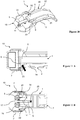
- the Figures 11A, 11B , and 11C show that when a user presses the pushers 7, 7 'of the locking mechanism 3, the displacement of the spar 14 causes a pressure on the manipulation member 9, causing the unlocking of the adjustment device.
- the spar 14 ' which does not cooperate with the length adjustment device when the clasp is closed, has been omitted.
- the arrow shown in black in the Figures 11A and 11C indicates the contact between the spar 14 and the pusher 9 during the activation of the member 7.
- said longitudinal members 14, 14 ' are arranged with respect to said manipulation member 7, 7' so as to move when the manipulation member 7, 7 'is activated by a user.
- the displacement of at least one of the longitudinal members 14 causes an unlocking of the locking mechanism 3.
- the spar 14 is caused to move in a direction orthogonal to the longitudinal direction of the bracelet when the manipulator 7 is activated. During this displacement of the spar 14 in the orthogonal direction, the spar 14 acts on the actuating member 9 of the length adjustment device 4, in order to unlock the locking mechanism 2.
- the activation of the manipulation member 7, 7 'by a user makes it possible both to unlock the locking mechanism 3 and to unlock the locking device.
- the pressure exerted on the pushers 7, 7 ' causes the unlocking of the locking mechanism 3, but not necessarily the opening of the clasp.
- To open the clasp it is necessary not only to unlock the locking mechanism 3, but also to actively lift the second blade 2 to deploy the clasp blades.
- the clasp remains closed and a length adjustment can be made.
- the user can release the pressure on the pushbutton (s) 7, 7 'and the locking mechanism 3 goes back to the locked position (rest position), without the clasp having been open.
- only the spar 14 and not the opposite spar 14 ' is arranged to be able to act on the actuating member 9, due to the asymmetry of the length adjustment device. Therefore, according to a preferred embodiment, simply activate one of the two manipulators. A user can hold the clasp between the thumb and forefinger so as to press only the pusher 7, for example, and in this way unlock the locking device without completely unlocking the locking mechanism 4.
- the manipulation member 7 is arranged to be able to act either directly or by a mechanism or an intermediate structure 14 on the actuating member 9 when the clasp is closed.
- this mechanism or this intermediate structure corresponds to the spar 14 of the second blade 2.
- each spar is secured to one of the two handling members, for example formed in a room with one of the two manipulators.
- one of the side rails 14 is not formed in one piece with the manipulation member 7, 7 ', but both are made in two or more pieces, which may or may not be integral with the one of the other.
- the two parts can be in direct contact or can cooperate via a mechanism and / or by one or more separate parts. In all these cases, it is preferred that the activation of the manipulation members 7, 7 'results in the displacement of the spars, preferably in an orthogonal direction.
- the clasp of the invention allows a length adjustment when the clasp is open and also when the clasp is closed.
- the locking device can be activated whether the clasp is open or closed.
- the user can press directly on the actuating member 9.
- the activation of the length adjustment device is effected by means of the first manipulation member 7.
- the first blade 1 is shown separately at the figure 10 .
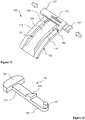
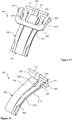
- the blade 1 comprises two parts, for example two semi-blades or two partial blades, a frame blade 30, shown in FIG. figure 8 , and the central blade 35, shown to Figures 7A and 7B .
- the first blade 1 comprises two separate parts 30, 35, made integral with one another, a first part 35 comprising the central support structure 6 and a second part 30 comprising two lateral side members 15, 15 ', between which the central support structure 6 is framed and / or attached.
- this assembly becomes unmountable.
- the two partial blades are thus rigidly connected so as to behave as a single piece.
- the frame blade 30 ( figure 8 ) comprises the two substantially parallel side members 15, 15 ', a transverse post 43 rigidly connecting the longitudinal members, and at the second end, a frame 18 having two lateral extensions 28 of the side members 15, 15' and a transverse plate 29.
- the frame 18 forms an opening in the first blade 1, making it possible to thread and frame the end of the bracelet strand which will be attached to the first fixing member 11.
- the clasp is connected to bracelet strands, the strand of The bracelet connected to the first fastening member 11 will pass over the transverse plate 29 and will be below the blades of the clasp, in contact with the wrist of the user.
- recesses or recesses 38 are arranged in the inner faces of the longitudinal members 15, 15 'intended to receive protuberances 39 arranged on the central blade 35, in order to form a retaining or attachment structure to enable the two blades to be connected.
- any other connection or interaction structure may be provided to allow a coupling between the two partial blades.
- the central blade 35 ( Figures 7A and 7B ) comprises the central support structure 6, carrying the length adjustment device 4.
- the recesses forming the channel 32 and the housing 36 are created in the central blade 35.
- the latter further comprises two lateral fins 41 intended to be in position. contact with the longitudinal members 15, 15 'when the two partial blades 30, 35 are assembled, and forming a common upper surface 21.
- a transverse recess 42 is formed in the lower face of the central blade 35 ( Figure 7B ), to clear a space in which the transverse amount 43 of the frame blade 30 comes to rest when the two partial blades are assembled ( Figure 6A ).
- the central blade 35 Towards its first end, the central blade 35 also has a transverse hole to allow articulation relative to the second blade and to contribute to the assembly between the partial blades 30, 35.
- the parts of the clasp of the invention can be manufactured, independently, of any suitable material.
- the clasps and / or their parts are made of metal.
- blades and functional parts are typically made of metal, for example steel, stainless steel, titanium, gold, silver, or any other metal or alloy of metals.
- the first blade 1, the first piece or the partial blade 35, and / or the piece carrying the length adjustment device 4 may comprise a non-metallic material.
- the first blade or the first piece 1 of the first blade is made of a material having a non-metallic material.
- the material comprising a non-metallic material is selected from the following: a material other than metal, a composite material, a plastic (polymer) and / or carbon fiber.
- a material other than metal e.g., aluminum, copper, magnesium, magnesium, magnesium, magnesium, calcium, magnesium, calcium, magnesium, calcium, magnesium, calcium, magnesium, magnesium, magnesium, magnesium, magnesium, magnesium, magnesium, magnesium, magnesium, magnesium, magnesium, magnesium, magnesium, magnesium, magnesium, magnesium, magnesium, magnesium, magnesium, magnesium, magnesium, magnesium, magnesium, magnesium, magnesium, magnesium, magnesium, magnesium, magnesium, magnesium, magnesium, magnesium, magnesium, magnesium, magnesium, magnesium, magnesium, magnesium, magnesium, magnesium, magnesium, magnesium, magnesium, magnesium, magnesium magnesium magnesium magnesium magnesium magnesium magnesium magnesium magnesium magnesium magnesium magnesium magnesium magnesium magnesium magnesium magnesium magnesium magnesium magnesium magnesium magnesium magnesium magnesium magnesium magnesium magnesium magnesium magnesium magnesium magnesium magnesium magnesium magnesium magnesium magnesium magnesium magnesium magnesium magnesium magnesium magnesium magnesium magnesium magnesium magnesium magnesium magnesium magnesium magnesium magnesium magnesium magnesium magnesium magnesium magnesium magnesium magnesium magnesium magnesium magnesium magnesium magnesium magnesium magnesium magnesium magnesium magnesium magnesium magnesium magnesium magnesium magnesium magnesium magnesium magnesium magnesium magnesium magnesium magnesium magnesium magnesium
- the first blade 1, the first piece 35, the first partial blade 35, and / or the blade carrying the length adjustment device is manufactured by injection and / or by injection molding. This applies to a part made of a material comprising a non-metallic material.
- the fact of making a blade or part of it by molding brings several advantages. On the one hand, when the part has a material other than metal materials, the weight of the part, compared to a metal part, is decreased. On the other hand, manufacturing costs are significantly lower.
- the assembly of the first blade 1 is made of the same material other than metal, for example one of the abovementioned materials, preferably a plastic material comprising carbon fiber.
- the clasp of the invention comprises a length adjustment device 4 housed in the workpiece 35 or the blade 1 comprising the non-metallic material.
- the piece 35 or the blade 1 comprising the (or non-metallic) material comprises one or more recesses 32, 36 intended to house one or several parts 5, 9, 34 which are part of the length adjustment device 4.
- Said parts 5, 9, 34 which are part of the length adjustment device 4 are chosen from the moving part 5, a part 9, 12, 34 having a jaw or tooth 34, intended to cooperate with the mobile 5, and an actuating member 9 arranged to allow the unlocking of the movable portion 5.
- one or more of the parts 5, 9, 12, 34 of the length adjustment device 4 are made of metal.
- the clasp comprises parts made of a material comprising a non-metallic material and other parts made of metal.
- the first blade may include a first partial blade 35 of a material having a non-metallic material, and a second partial blade or metal frame blade 30.
- a full blade 1 is made of a material having non-metallic components
- another blade 2 is made of metal.
- a blade or partial blade made of a material having a non-metallic material can accommodate and / or cooperate with metal parts.
- the invention also covers the possibility that two, more or all of the clasp blades are made of a material comprising a non-metallic material, and the parts housed in these blades may be metallic or comprise non-metallic materials. , for example.
- a material comprising non-metallic material may be made entirely of a non-metallic material, for example plastic and / or carbon fiber, or may comprise a mixture of one or more metals and one or more non-metallic materials .
- Clasp 100 includes a first blade 101 having a central structure 106, the first blade being hinged to a second blade 102 having two side rails 114, 114 'at a first end of the blades.
- the moving part, which emerges at the free end of the structure 106, is not visible, but the manipulation member 109 is arranged projecting in a lateral flank of the structure 106 (shown on the left side of the structure 106 at the figure 13 ).
- the two longitudinal members 114, 114 ' are arranged laterally with respect to the central structure 106 of the first blade 101.
- a particularity of the clasp of the figure 13 is that the beams 114, 114 'are connected to pushers 107, 107 ', respectively, arranged at the opposite lateral sides with respect to the lateral side of the respective spar.
- the spar 114 is preferably connected to the manipulation member 107, and the spar 114 'to the member 107'.
- the two parts or entities comprising the longitudinal members 114, 114 'and the members 107, 107' intersect, preferably at the second end of the longitudinal members.
- a spar and the member to which it is connected may form a member reminding the letter L.
- This element may be formed in one piece or in several pieces made integral with one another.
- Arranging the complementary fastening members 22, 23 on the outer flanks of the central structure 106 and the inner flanks of each of the longitudinal members 114, 114 ' may be advantageous.
- the extensions 28 or the elevation structures 31 of the embodiment shown in FIGS. figure 1-11 no longer necessary to arrange the complementary members on the side of the first blade 1.
- a first blade comprising or consisting essentially of the central support structure 106 could be sufficient.
- the piece 119 comprising the pusher 109, the transverse bar 112, the jaw or the opposing tooth 134 also has an extension 140, extending the bar 112 in the orthogonal direction.
- the extension 140 emerges from the side flank opposite to that of the pusher 109 on the central structure 106 (not visible).
- a pin 141, arranged on the extension 140 operates as a pull rod or a hooking member, making it possible to perform a pulling force on the piece 119.
- a hole 144 is formed in the spar 114 ', arranged to receive the pin 141 when the second blade 102 is folded on the first blade 101.
- the spar 114 is connected to the pull tab 141 so that the actuation of the member 107 'pulls on the pull tab, allowing the unlocking device to be released when the actuating member is activated.
- the return means are arranged to hold the locking device in the locked position. These return means can be arranged between the pusher 109 and the structure 106, as shown in FIGS. Figures 9A and 9B .
- a second actuating member 141 may be present instead of the pusher 109 or may exist in addition to the pusher 109.
- the presence of an actuating member in the form of a zipper 141 is particularly preferred when the locking mechanism described above is based on a spacing instead of the approximation of the longitudinal members of the second blade 102.
- connection means for example a pair of hooks or a connection by a pin and a hole, arranged so that when spacing at least one of the two longitudinal members 114, 114 ', traction is performed on the part 119, allowing the release of the release device at the time of the activation of the actuating member.
- the element 119 can be made of several separate parts, made preferably integral.
- the locking device comprises both a pusher 109 and a pull tab 141.
- the activation of each of the two allows unblocking of the locking device.
- the pusher can preferably be actuated by a carrier having opened the clasp, for example by pressing with a finger on the pusher, while the zipper is preferably activated indirectly, by the movement of at least one spar during activation. locking mechanism.
- the figures 14 and 15 show a clasp 200 according to a third embodiment.
- a first blade 201 is hinged to a second blade 202 at a first end of the blades.
- the first blade 201 comprises a central support structure 206.
- a movable part 205 is housed, arranged in a manner of the end of the structure 106.
- structure 206 contains recesses or recesses similar to those described above, for accommodating the movable portion 205 and the part 219 comprising the actuating member 209.
- a first fastener 211 realized in the form of a transverse bar, is connected to the moving part 205.
- the second blade 202 comprises two side rails 214, 214 ', articulated at the first end and stabilized towards the second end by a transverse tube not shown.
- a difference of the clasp 200 from the previous clasps is that the actuator 209 emerges on the right side of the central structure 206, as shown in FIGS. figures 14 and 15 . In the previous clasps, the locking device had an opposite orientation.
- the rails 214, 214 ' are arranged laterally with respect to the structure 206 when the clasp is closed.
- Each spar is connected to a respective manipulation member 207, 207 'by an orthogonally oriented rod 247 having a diameter which is smaller than the diameter of the members 207, 207.
- the clasp 200 comprises a U-shaped loop 220, whose two free ends have holes in which the rods 247 are threaded.
- the loop 220 can pivot about the axis defined by the rods 247 while stabilizing the ends of the longitudinal members 214, 214 '.
- a second fastener is connected to the loop 220.
- the activation of the manipulation members 207, 207 ', by pressure causes a coming together of the longitudinal members 214, 214'.
- One of the two longitudinal members, the spar 214 ' is arranged to act on the actuating member 209 and unlock the locking mechanism, during its displacement, according to the same principle described above.
- the first blade 214 comprises, on its underside, plates or lateral fins 215, on which the longitudinal members 214, 214 'come to rest when the clasp is closed.
- Each of the plates 215 has an edge or an elevated structure 231 for containing the respective spar.
- a hooking member On the inside face of the edge 231 is a hooking member, arranged to cooperate with a complementary member arranged on the outer side of the respective spar. Together, the pair of hooking members lock the clasp in the closed position, when the two blades are folded towards each other, as described with respect to the embodiment shown in FIGS. Figures 1-12 .
- the simultaneous activation of the two pushers 207, 207 'by pressure causes a coming together of the longitudinal members and the separation of complementary hooking members, to unfold the blades 201, 202 to open the clasp.
- one aspect of the invention is the arrangement of the length adjustment device on a support structure of a first blade and in the possibility of the activation of the adjusting device by a locking mechanism based on longitudinal members of a second blade, the ends of which can move apart or approached preferably along an orthogonal axis or in a plane orthogonal.
- longitudinal members come closer when unlocking, at least one of them acts preferably on a pusher.
- side members apart during unlocking at least one of them acts preferably on a pull.
- the skilled person will not encounter any particular difficulty to adapt the content of the present disclosure to his own needs and implement a clasp, especially for a timepiece, without departing from the scope of the present invention.
- a locking mechanism different from that shown in the figures, while arranging the last so that an activation of a manipulator causes the unlocking of the locking device.
- the length adjustment device according to the invention can be adapted to other types of clasps, especially for wristwatch.
Landscapes
- Buckles (AREA)
Priority Applications (4)
| Application Number | Priority Date | Filing Date | Title |
|---|---|---|---|
| EP17177222.1A EP3417735A1 (de) | 2017-06-21 | 2017-06-21 | Armbandverschluss, der eine reguliervorrichtung der länge des armbands umfasst |
| CN201880041533.0A CN110769716B (zh) | 2017-06-21 | 2018-06-21 | 具有调节手链长度的装置的手链扣环 |
| EP18740109.6A EP3641584B1 (de) | 2017-06-21 | 2018-06-21 | Armbandverschluss, der eine reguliervorrichtung der länge des armbands umfasst |
| PCT/EP2018/066619 WO2018234474A1 (fr) | 2017-06-21 | 2018-06-21 | Fermoir pour bracelet comportant un dispositif de réglage de longueur du bracelet |
Applications Claiming Priority (1)
| Application Number | Priority Date | Filing Date | Title |
|---|---|---|---|
| EP17177222.1A EP3417735A1 (de) | 2017-06-21 | 2017-06-21 | Armbandverschluss, der eine reguliervorrichtung der länge des armbands umfasst |
Publications (1)
| Publication Number | Publication Date |
|---|---|
| EP3417735A1 true EP3417735A1 (de) | 2018-12-26 |
Family
ID=59101366
Family Applications (1)
| Application Number | Title | Priority Date | Filing Date |
|---|---|---|---|
| EP17177222.1A Withdrawn EP3417735A1 (de) | 2017-06-21 | 2017-06-21 | Armbandverschluss, der eine reguliervorrichtung der länge des armbands umfasst |
Country Status (1)
| Country | Link |
|---|---|
| EP (1) | EP3417735A1 (de) |
Citations (11)
| Publication number | Priority date | Publication date | Assignee | Title |
|---|---|---|---|---|
| EP0383039A1 (de) | 1989-02-16 | 1990-08-22 | Petitjean S.A. | Faltverschluss für Armbänder |
| EP0913106A1 (de) | 1997-10-30 | 1999-05-06 | Dexel S.A. | Faltverschluss für Armband |
| CH698981B1 (fr) | 2005-12-21 | 2009-12-31 | Taramax S A | Dispositif de réglage de longueur pour bracelet, fermoire de bracelet et bracelet munis d'un tel dispositif. |
| CH700230A2 (fr) | 2009-01-09 | 2010-07-15 | Richemont Int Sa | Fermoir de bracelet comportant un dispositif de réglage fin de la longueur utile du bracelet. |
| EP2361523A1 (de) | 2010-02-23 | 2011-08-31 | Winox Sa | Verschluss für Armband |
| EP2452583A1 (de) | 2010-11-10 | 2012-05-16 | Samia Ferrad | Uhrenarmband |
| CH704335A1 (fr) | 2011-01-13 | 2012-07-13 | Thi Technologies Horlogeres Ind S A | Fermoir extensible pour bracelet notamment d'une montre. |
| CH705149A1 (fr) | 2011-06-30 | 2012-12-31 | Thi Technologies Horlogeres Ind S A | Fermoir extensible pour bracelet notamment d'une montre. |
| EP2740381A1 (de) * | 2012-12-04 | 2014-06-11 | Omega SA | Verstellbarer Armbandverschluss |
| EP2868222A1 (de) * | 2013-11-01 | 2015-05-06 | Dexel S.A. | Armbandverschluss, der eine Reguliervorrichtung der Länge des Armbands umfasst |
| EP2888967A1 (de) * | 2013-12-26 | 2015-07-01 | The Swatch Group Management Services AG | Armbandverschluss, der eine Reguliervorrichtung der Nutzlänge des Armbands umfasst |
-
2017
- 2017-06-21 EP EP17177222.1A patent/EP3417735A1/de not_active Withdrawn
Patent Citations (12)
| Publication number | Priority date | Publication date | Assignee | Title |
|---|---|---|---|---|
| EP0383039A1 (de) | 1989-02-16 | 1990-08-22 | Petitjean S.A. | Faltverschluss für Armbänder |
| EP0913106A1 (de) | 1997-10-30 | 1999-05-06 | Dexel S.A. | Faltverschluss für Armband |
| EP0913106B1 (de) | 1997-10-30 | 2003-01-15 | Dexel S.A. | Faltverschluss für Armband |
| CH698981B1 (fr) | 2005-12-21 | 2009-12-31 | Taramax S A | Dispositif de réglage de longueur pour bracelet, fermoire de bracelet et bracelet munis d'un tel dispositif. |
| CH700230A2 (fr) | 2009-01-09 | 2010-07-15 | Richemont Int Sa | Fermoir de bracelet comportant un dispositif de réglage fin de la longueur utile du bracelet. |
| EP2361523A1 (de) | 2010-02-23 | 2011-08-31 | Winox Sa | Verschluss für Armband |
| EP2452583A1 (de) | 2010-11-10 | 2012-05-16 | Samia Ferrad | Uhrenarmband |
| CH704335A1 (fr) | 2011-01-13 | 2012-07-13 | Thi Technologies Horlogeres Ind S A | Fermoir extensible pour bracelet notamment d'une montre. |
| CH705149A1 (fr) | 2011-06-30 | 2012-12-31 | Thi Technologies Horlogeres Ind S A | Fermoir extensible pour bracelet notamment d'une montre. |
| EP2740381A1 (de) * | 2012-12-04 | 2014-06-11 | Omega SA | Verstellbarer Armbandverschluss |
| EP2868222A1 (de) * | 2013-11-01 | 2015-05-06 | Dexel S.A. | Armbandverschluss, der eine Reguliervorrichtung der Länge des Armbands umfasst |
| EP2888967A1 (de) * | 2013-12-26 | 2015-07-01 | The Swatch Group Management Services AG | Armbandverschluss, der eine Reguliervorrichtung der Nutzlänge des Armbands umfasst |
Similar Documents
| Publication | Publication Date | Title |
|---|---|---|
| EP3758542B1 (de) | Armbandverschluss, der eine reguliervorrichtung der länge des armbands umfasst | |
| EP3769640B1 (de) | Verschluss für uhrenarmband | |
| EP3419470B1 (de) | Armbandverschluss, der eine reguliervorrichtung der länge des armbands umfasst | |
| EP3213654B1 (de) | System aus einziehbaren stiften zum festmachen eines armbands an einer armbanduhr | |
| EP2868222B1 (de) | Armbandverschluss, der eine Reguliervorrichtung der Länge des Armbands umfasst | |
| EP2361523B1 (de) | Verschluss für Armband | |
| EP4059374B1 (de) | Armbandverschluss, der eine vorrichtung zur einstellung der länge des armbands umfasst, die eine rasche und bequeme anpassung ermöglicht | |
| EP3470935B1 (de) | Einrastsystem, beispielsweise zum festmachen eines armbands an einer armbanduhr | |
| EP2663208A1 (de) | Faltschliesse für ein band, insbesondere ein uhrenarmband | |
| EP2644050A1 (de) | Aufklappbarer Verschluss für Armband | |
| CH705149B1 (fr) | Fermoir extensible pour bracelet notamment d'une montre. | |
| EP3641584B1 (de) | Armbandverschluss, der eine reguliervorrichtung der länge des armbands umfasst | |
| EP3417734B1 (de) | Armbandverschluss, der eine reguliervorrichtung der länge des armbands umfasst | |
| EP4238447A1 (de) | Faltverschluss | |
| EP3565431B1 (de) | Verbindungsvorrichtung für armband | |
| CH715870A1 (fr) | Système de fixation pour bracelets. | |
| FR3094873A1 (fr) | mini boucle déployante avec longerons rigides | |
| EP3170420B1 (de) | Armbandverschluss, der eine reguliervorrichtung der länge des armbands umfasst | |
| EP4266942A1 (de) | Gurt | |
| EP3417735A1 (de) | Armbandverschluss, der eine reguliervorrichtung der länge des armbands umfasst | |
| EP4233628B1 (de) | Verschluss für armband einer armbanduhr | |
| EP1192872B1 (de) | Verschluss für ein Uhrarmband | |
| EP2476334B1 (de) | Verschluss | |
| CH716147B1 (fr) | Fermoir à boucle déployante. | |
| CH702308B1 (fr) | Objet portable ayant un bracelet interchangeable. |
Legal Events
| Date | Code | Title | Description |
|---|---|---|---|
| PUAI | Public reference made under article 153(3) epc to a published international application that has entered the european phase |
Free format text: ORIGINAL CODE: 0009012 |
|
| AK | Designated contracting states |
Kind code of ref document: A1 Designated state(s): AL AT BE BG CH CY CZ DE DK EE ES FI FR GB GR HR HU IE IS IT LI LT LU LV MC MK MT NL NO PL PT RO RS SE SI SK SM TR |
|
| AX | Request for extension of the european patent |
Extension state: BA ME |
|
| STAA | Information on the status of an ep patent application or granted ep patent |
Free format text: STATUS: THE APPLICATION IS DEEMED TO BE WITHDRAWN |
|
| 18D | Application deemed to be withdrawn |
Effective date: 20190627 |