EP3417822B1 - Mikrowellen- und hochfrequenz-energieübertragende gewebeablationssysteme - Google Patents
Mikrowellen- und hochfrequenz-energieübertragende gewebeablationssysteme Download PDFInfo
- Publication number
- EP3417822B1 EP3417822B1 EP18178349.9A EP18178349A EP3417822B1 EP 3417822 B1 EP3417822 B1 EP 3417822B1 EP 18178349 A EP18178349 A EP 18178349A EP 3417822 B1 EP3417822 B1 EP 3417822B1
- Authority
- EP
- European Patent Office
- Prior art keywords
- outer shaft
- surgical instrument
- microwave
- distal portion
- tissue
- Prior art date
- Legal status (The legal status is an assumption and is not a legal conclusion. Google has not performed a legal analysis and makes no representation as to the accuracy of the status listed.)
- Active
Links
Images






Classifications
-
- A—HUMAN NECESSITIES
- A61—MEDICAL OR VETERINARY SCIENCE; HYGIENE
- A61B—DIAGNOSIS; SURGERY; IDENTIFICATION
- A61B18/00—Surgical instruments, devices or methods for transferring non-mechanical forms of energy to or from the body
- A61B18/04—Surgical instruments, devices or methods for transferring non-mechanical forms of energy to or from the body by heating
- A61B18/12—Surgical instruments, devices or methods for transferring non-mechanical forms of energy to or from the body by heating by passing a current through the tissue to be heated, e.g. high-frequency current
- A61B18/14—Probes or electrodes therefor
- A61B18/1482—Probes or electrodes therefor having a long rigid shaft for accessing the inner body transcutaneously in minimal invasive surgery, e.g. laparoscopy
-
- A—HUMAN NECESSITIES
- A61—MEDICAL OR VETERINARY SCIENCE; HYGIENE
- A61B—DIAGNOSIS; SURGERY; IDENTIFICATION
- A61B18/00—Surgical instruments, devices or methods for transferring non-mechanical forms of energy to or from the body
- A61B18/04—Surgical instruments, devices or methods for transferring non-mechanical forms of energy to or from the body by heating
- A61B18/12—Surgical instruments, devices or methods for transferring non-mechanical forms of energy to or from the body by heating by passing a current through the tissue to be heated, e.g. high-frequency current
- A61B18/1206—Generators therefor
-
- A—HUMAN NECESSITIES
- A61—MEDICAL OR VETERINARY SCIENCE; HYGIENE
- A61B—DIAGNOSIS; SURGERY; IDENTIFICATION
- A61B18/00—Surgical instruments, devices or methods for transferring non-mechanical forms of energy to or from the body
- A61B18/18—Surgical instruments, devices or methods for transferring non-mechanical forms of energy to or from the body by applying electromagnetic radiation, e.g. microwaves
- A61B18/1815—Surgical instruments, devices or methods for transferring non-mechanical forms of energy to or from the body by applying electromagnetic radiation, e.g. microwaves using microwaves
-
- A—HUMAN NECESSITIES
- A61—MEDICAL OR VETERINARY SCIENCE; HYGIENE
- A61B—DIAGNOSIS; SURGERY; IDENTIFICATION
- A61B17/00—Surgical instruments, devices or methods
- A61B2017/00973—Surgical instruments, devices or methods pedal-operated
-
- A—HUMAN NECESSITIES
- A61—MEDICAL OR VETERINARY SCIENCE; HYGIENE
- A61B—DIAGNOSIS; SURGERY; IDENTIFICATION
- A61B18/00—Surgical instruments, devices or methods for transferring non-mechanical forms of energy to or from the body
- A61B2018/00005—Cooling or heating of the probe or tissue immediately surrounding the probe
- A61B2018/00011—Cooling or heating of the probe or tissue immediately surrounding the probe with fluids
-
- A—HUMAN NECESSITIES
- A61—MEDICAL OR VETERINARY SCIENCE; HYGIENE
- A61B—DIAGNOSIS; SURGERY; IDENTIFICATION
- A61B18/00—Surgical instruments, devices or methods for transferring non-mechanical forms of energy to or from the body
- A61B2018/00315—Surgical instruments, devices or methods for transferring non-mechanical forms of energy to or from the body for treatment of particular body parts
- A61B2018/00529—Liver
-
- A—HUMAN NECESSITIES
- A61—MEDICAL OR VETERINARY SCIENCE; HYGIENE
- A61B—DIAGNOSIS; SURGERY; IDENTIFICATION
- A61B18/00—Surgical instruments, devices or methods for transferring non-mechanical forms of energy to or from the body
- A61B2018/00571—Surgical instruments, devices or methods for transferring non-mechanical forms of energy to or from the body for achieving a particular surgical effect
- A61B2018/00577—Ablation
-
- A—HUMAN NECESSITIES
- A61—MEDICAL OR VETERINARY SCIENCE; HYGIENE
- A61B—DIAGNOSIS; SURGERY; IDENTIFICATION
- A61B18/00—Surgical instruments, devices or methods for transferring non-mechanical forms of energy to or from the body
- A61B2018/00571—Surgical instruments, devices or methods for transferring non-mechanical forms of energy to or from the body for achieving a particular surgical effect
- A61B2018/00601—Cutting
-
- A—HUMAN NECESSITIES
- A61—MEDICAL OR VETERINARY SCIENCE; HYGIENE
- A61B—DIAGNOSIS; SURGERY; IDENTIFICATION
- A61B18/00—Surgical instruments, devices or methods for transferring non-mechanical forms of energy to or from the body
- A61B2018/00571—Surgical instruments, devices or methods for transferring non-mechanical forms of energy to or from the body for achieving a particular surgical effect
- A61B2018/00607—Coagulation and cutting with the same instrument
-
- A—HUMAN NECESSITIES
- A61—MEDICAL OR VETERINARY SCIENCE; HYGIENE
- A61B—DIAGNOSIS; SURGERY; IDENTIFICATION
- A61B18/00—Surgical instruments, devices or methods for transferring non-mechanical forms of energy to or from the body
- A61B2018/0091—Handpieces of the surgical instrument or device
- A61B2018/00916—Handpieces of the surgical instrument or device with means for switching or controlling the main function of the instrument or device
- A61B2018/00928—Handpieces of the surgical instrument or device with means for switching or controlling the main function of the instrument or device by sending a signal to an external energy source
-
- A—HUMAN NECESSITIES
- A61—MEDICAL OR VETERINARY SCIENCE; HYGIENE
- A61B—DIAGNOSIS; SURGERY; IDENTIFICATION
- A61B18/00—Surgical instruments, devices or methods for transferring non-mechanical forms of energy to or from the body
- A61B2018/0091—Handpieces of the surgical instrument or device
- A61B2018/00916—Handpieces of the surgical instrument or device with means for switching or controlling the main function of the instrument or device
- A61B2018/0094—Types of switches or controllers
- A61B2018/00946—Types of switches or controllers slidable
-
- A—HUMAN NECESSITIES
- A61—MEDICAL OR VETERINARY SCIENCE; HYGIENE
- A61B—DIAGNOSIS; SURGERY; IDENTIFICATION
- A61B18/00—Surgical instruments, devices or methods for transferring non-mechanical forms of energy to or from the body
- A61B2018/0091—Handpieces of the surgical instrument or device
- A61B2018/00916—Handpieces of the surgical instrument or device with means for switching or controlling the main function of the instrument or device
- A61B2018/00958—Handpieces of the surgical instrument or device with means for switching or controlling the main function of the instrument or device for switching between different working modes of the main function
-
- A—HUMAN NECESSITIES
- A61—MEDICAL OR VETERINARY SCIENCE; HYGIENE
- A61B—DIAGNOSIS; SURGERY; IDENTIFICATION
- A61B18/00—Surgical instruments, devices or methods for transferring non-mechanical forms of energy to or from the body
- A61B2018/00982—Surgical instruments, devices or methods for transferring non-mechanical forms of energy to or from the body combined with or comprising means for visual or photographic inspections inside the body, e.g. endoscopes
-
- A—HUMAN NECESSITIES
- A61—MEDICAL OR VETERINARY SCIENCE; HYGIENE
- A61B—DIAGNOSIS; SURGERY; IDENTIFICATION
- A61B18/00—Surgical instruments, devices or methods for transferring non-mechanical forms of energy to or from the body
- A61B2018/00994—Surgical instruments, devices or methods for transferring non-mechanical forms of energy to or from the body combining two or more different kinds of non-mechanical energy or combining one or more non-mechanical energies with ultrasound
-
- A—HUMAN NECESSITIES
- A61—MEDICAL OR VETERINARY SCIENCE; HYGIENE
- A61B—DIAGNOSIS; SURGERY; IDENTIFICATION
- A61B18/00—Surgical instruments, devices or methods for transferring non-mechanical forms of energy to or from the body
- A61B18/04—Surgical instruments, devices or methods for transferring non-mechanical forms of energy to or from the body by heating
- A61B18/12—Surgical instruments, devices or methods for transferring non-mechanical forms of energy to or from the body by heating by passing a current through the tissue to be heated, e.g. high-frequency current
- A61B18/1206—Generators therefor
- A61B2018/1246—Generators therefor characterised by the output polarity
- A61B2018/1253—Generators therefor characterised by the output polarity monopolar
-
- A—HUMAN NECESSITIES
- A61—MEDICAL OR VETERINARY SCIENCE; HYGIENE
- A61B—DIAGNOSIS; SURGERY; IDENTIFICATION
- A61B18/00—Surgical instruments, devices or methods for transferring non-mechanical forms of energy to or from the body
- A61B18/04—Surgical instruments, devices or methods for transferring non-mechanical forms of energy to or from the body by heating
- A61B18/12—Surgical instruments, devices or methods for transferring non-mechanical forms of energy to or from the body by heating by passing a current through the tissue to be heated, e.g. high-frequency current
- A61B18/1206—Generators therefor
- A61B2018/1246—Generators therefor characterised by the output polarity
- A61B2018/126—Generators therefor characterised by the output polarity bipolar
-
- A—HUMAN NECESSITIES
- A61—MEDICAL OR VETERINARY SCIENCE; HYGIENE
- A61B—DIAGNOSIS; SURGERY; IDENTIFICATION
- A61B18/00—Surgical instruments, devices or methods for transferring non-mechanical forms of energy to or from the body
- A61B18/18—Surgical instruments, devices or methods for transferring non-mechanical forms of energy to or from the body by applying electromagnetic radiation, e.g. microwaves
- A61B18/1815—Surgical instruments, devices or methods for transferring non-mechanical forms of energy to or from the body by applying electromagnetic radiation, e.g. microwaves using microwaves
- A61B2018/1823—Generators therefor
-
- A—HUMAN NECESSITIES
- A61—MEDICAL OR VETERINARY SCIENCE; HYGIENE
- A61B—DIAGNOSIS; SURGERY; IDENTIFICATION
- A61B18/00—Surgical instruments, devices or methods for transferring non-mechanical forms of energy to or from the body
- A61B18/18—Surgical instruments, devices or methods for transferring non-mechanical forms of energy to or from the body by applying electromagnetic radiation, e.g. microwaves
- A61B18/1815—Surgical instruments, devices or methods for transferring non-mechanical forms of energy to or from the body by applying electromagnetic radiation, e.g. microwaves using microwaves
- A61B2018/183—Surgical instruments, devices or methods for transferring non-mechanical forms of energy to or from the body by applying electromagnetic radiation, e.g. microwaves using microwaves characterised by the type of antenna
- A61B2018/1838—Dipole antennas
-
- A—HUMAN NECESSITIES
- A61—MEDICAL OR VETERINARY SCIENCE; HYGIENE
- A61B—DIAGNOSIS; SURGERY; IDENTIFICATION
- A61B18/00—Surgical instruments, devices or methods for transferring non-mechanical forms of energy to or from the body
- A61B18/18—Surgical instruments, devices or methods for transferring non-mechanical forms of energy to or from the body by applying electromagnetic radiation, e.g. microwaves
- A61B18/1815—Surgical instruments, devices or methods for transferring non-mechanical forms of energy to or from the body by applying electromagnetic radiation, e.g. microwaves using microwaves
- A61B2018/183—Surgical instruments, devices or methods for transferring non-mechanical forms of energy to or from the body by applying electromagnetic radiation, e.g. microwaves using microwaves characterised by the type of antenna
- A61B2018/1846—Helical antennas
-
- A—HUMAN NECESSITIES
- A61—MEDICAL OR VETERINARY SCIENCE; HYGIENE
- A61B—DIAGNOSIS; SURGERY; IDENTIFICATION
- A61B18/00—Surgical instruments, devices or methods for transferring non-mechanical forms of energy to or from the body
- A61B18/18—Surgical instruments, devices or methods for transferring non-mechanical forms of energy to or from the body by applying electromagnetic radiation, e.g. microwaves
- A61B18/1815—Surgical instruments, devices or methods for transferring non-mechanical forms of energy to or from the body by applying electromagnetic radiation, e.g. microwaves using microwaves
- A61B2018/183—Surgical instruments, devices or methods for transferring non-mechanical forms of energy to or from the body by applying electromagnetic radiation, e.g. microwaves using microwaves characterised by the type of antenna
- A61B2018/1853—Monopole antennas
-
- A—HUMAN NECESSITIES
- A61—MEDICAL OR VETERINARY SCIENCE; HYGIENE
- A61B—DIAGNOSIS; SURGERY; IDENTIFICATION
- A61B18/00—Surgical instruments, devices or methods for transferring non-mechanical forms of energy to or from the body
- A61B18/18—Surgical instruments, devices or methods for transferring non-mechanical forms of energy to or from the body by applying electromagnetic radiation, e.g. microwaves
- A61B18/1815—Surgical instruments, devices or methods for transferring non-mechanical forms of energy to or from the body by applying electromagnetic radiation, e.g. microwaves using microwaves
- A61B2018/1869—Surgical instruments, devices or methods for transferring non-mechanical forms of energy to or from the body by applying electromagnetic radiation, e.g. microwaves using microwaves with an instrument interstitially inserted into the body, e.g. needles
-
- A—HUMAN NECESSITIES
- A61—MEDICAL OR VETERINARY SCIENCE; HYGIENE
- A61B—DIAGNOSIS; SURGERY; IDENTIFICATION
- A61B2218/00—Details of surgical instruments, devices or methods for transferring non-mechanical forms of energy to or from the body
- A61B2218/001—Details of surgical instruments, devices or methods for transferring non-mechanical forms of energy to or from the body having means for irrigation and/or aspiration of substances to and/or from the surgical site
- A61B2218/002—Irrigation
-
- A—HUMAN NECESSITIES
- A61—MEDICAL OR VETERINARY SCIENCE; HYGIENE
- A61B—DIAGNOSIS; SURGERY; IDENTIFICATION
- A61B2218/00—Details of surgical instruments, devices or methods for transferring non-mechanical forms of energy to or from the body
- A61B2218/001—Details of surgical instruments, devices or methods for transferring non-mechanical forms of energy to or from the body having means for irrigation and/or aspiration of substances to and/or from the surgical site
- A61B2218/007—Aspiration
Definitions
- the present disclosure relates to a tissue ablation system, and more particularly to a combination microwave/radiofrequency ablation system for coagulating and resecting tissues.
- apparatus for use in ablation procedures include a power generation source, e.g., a microwave or radio frequency (RF) electrosurgical generator that functions as an energy source and a surgical instrument (e.g., microwave ablation probe having an antenna assembly) for directing energy to the target tissue.
- RF radio frequency
- the generator and surgical instrument are typically operatively coupled by a cable assembly having a plurality of conductors for transmitting energy from the generator to the instrument, and for communicating control, feedback, and identification signals between the instrument and the generator.
- monopole and dipole antenna assemblies microwave energy generally radiates perpendicularly away from the axis of the conductor.
- Monopole antenna assemblies typically include a single, elongated conductor.
- a typical dipole antenna assembly includes two elongated conductors that are linearly-aligned and positioned end-to-end relative to one another with an electrical insulator placed therebetween.
- Helical antenna assemblies include helically-shaped conductor configurations of various dimensions, e.g., diameter and length.
- the main modes of operation of a helical antenna assembly are normal mode (broadside), in which the field radiated by the helix is maximum in a perpendicular plane to the helix axis, and axial mode (end fire), in which maximum radiation is along the helix axis.
- microwave probe One use for a microwave probe is to dissect solid organs, such as liver or kidney, to remove entire diseased portions of the organ. During these procedures, it is important that blood loss from the dissected organ is minimized without compromising the efficacy of the procedure. It is also of particular importance to keep the procedure simple by reducing the number of surgical instruments used while also keeping the overall procedure time at a minimum.
- US 2017100186 discloses an electrosurgical instrument that includes an elongated housing having proximal and distal ends.
- the proximal end is configured to couple to a source of electrosurgical energy via first and second channels extending along a length of the housing to the distal end thereof.
- the distal end includes a reflector having a dielectric load operably coupled thereto and configured to receive at least a portion of the first conductor therein.
- electrosurgical energy is transmitted to the first channel and reflected from the reflector to electrosurgically treat tissue.
- the reflector is configured to receive at least a portion of the second channel therein.
- electrosurgical energy is transmitted to the second channel to dissect tissue.
- US 2014/358140 discloses microwave antennas and other energy delivery systems, as well as systems and methods for the delivery of various medical components within or on a body for performing one or more medical procedures.
- Medical systems comprising a combination of one or more medical components and one or more elongate steerable or non-steerable arms that are adapted to mechanically manipulate the one or more medical components.
- the catheter includes an elongated flexible tubular member adapted to be inserted into a vessel in the body of a patient.
- a transmission line suitable for transmitting electromagnetic energy is received within the tubular member.
- An antenna is coupled to the transmission line for generating an electric field sufficiently strong to cause tissue ablation.
- the antenna takes the form of an antenna coil that is oriented such that its longitudinal axis extends substantially perpendicular to the longitudinal axis of the flexible tubular member.
- a plurality of such laterally oriented antenna coils are provided at longitudinally spaced locations relative to the catheter axis.
- the antenna coil is spirally wound.
- the coil may be wound in a substantially conical or frusto-conical manner expanding either distally or proximately, or the antenna coil may be wound in a substantially flat coil.
- US 2010286687 discloses a therapy needle that may include any of a number of features.
- One feature of the therapy needle is that it can apply microwave energy to tissue to produce a coagulative spherical volumetric ablation of the tissue.
- the volumetric ablation may have a diameter ranging from 1 cm to 4 cm and can be formed in less than 3 minutes.
- Another feature of the therapy needle is that it can utilize an electric cutting device on a distal portion of the needle to cut a hole in high density tissue. Methods associated with use of the therapy needle are also covered.
- a method of resecting a portion of tissue includes positioning a microwave antenna of a surgical instrument adjacent a portion of tissue, transmitting microwave energy into the portion of the tissue, thereby precoagulating the portion of the tissue, deactivating the transmission of the microwave energy, and moving a distal portion of an outer shaft of the urgical instrument along the tissue while transmitting radiofrequency energy from an electrode of the surgical instrument into the tissue, thereby resecting the portion of the tissue.
- parallel and perpendicular are understood to include relative configurations that are substantially parallel and substantially perpendicular up to about + or - 10 degrees from true parallel and true perpendicular.
- tissue ablation systems including various embodiments of a surgical instrument and methods of use thereof are described in detail with reference to the drawings, in which like reference numerals designate identical or corresponding elements in each of the several views.
- distal refers to that portion of the tissue ablation system or component thereof, that is closer to the patient
- proximal refers to that portion of the tissue ablation system or component thereof, that is farther from the patient.
- one embodiment of the disclosed surgical instruments includes a wedge-shaped outer shaft, a microwave antenna disposed within a distal portion of the outer shaft, and a monopolar electrode or bipolar electrodes disposed on the distal portion of the outer shaft.
- the microwave antenna is activated to transmit microwave energy out of an apex of the outer shaft and into tissue to precoagulate tissue.
- the microwave antenna is deactivated, and the electrode is activated to transmit radiofrequency energy into the tissue while moving the distal portion of the outer shaft along an outer surface of the tissue.
- the radiofrequency energy cuts or resects the precoagulated tissue to remove a portion of the tissue with minimal to no bleeding occurring.
- pre-coagulate means heating tissue to the extent necessary to prevent blood from flowing from the heated tissue upon resecting the tissue.
- microwave generally refers to electromagnetic waves in the frequency range of 300 megahertz (MHz) (3 x 10⁸ cycles/second) to 300 gigahertz (GHz) (3 x 10¹¹ cycles/second).
- tissue ablation generally refers to any ablation procedure, such as, for example, microwave ablation, radiofrequency (RF) ablation, or microwave or RF ablation-assisted resection.
- RF radiofrequency
- transmission line generally refers to any transmission medium that can be used for the propagation of signals from one point to another.
- fluid generally refers to a liquid, a gas or both.
- controller generally refers to any electrical device that employs digital and/or analog components to generate digital and/or analog signals to control or drive another device.
- controller may refer to a digital signal processor, a microcontroller, or a computer having a processor, a memory, and input/output ports for carrying out some of the methods described herein.
- Various embodiments of the presently disclosed surgical instruments are suitable for tissue ablation and for use to pre-coagulate tissue for microwave ablation-assisted surgical resection.
- various methods described hereinbelow are targeted toward microwave ablation and the destruction and/or resection of targeted tissue, methods for directing electromagnetic radiation may be used with other therapies in which the target tissue is partially destroyed, damaged, or dissected.
- teachings of the present disclosure may apply to a dipole, monopole, helical, or other suitable type of microwave antenna.
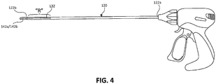
- a dual microwave/RF energy ablation and cutting system 10 is illustrated and generally includes a tissue ablation instrument 100 operably coupled to a microwave generator 12, an electrosurgical generator 14, and a surgical suction pump 16.
- the microwave generator 12 generates a microwave energy signal that is transmitted to a radiating section "R" ( FIG. 2 ) of the surgical instrument 100 via a coaxial cable 102.
- the microwave energy generated by the microwave generator 12 may be in the range of about 915 MHz to about 25.0 GHz. In some embodiments, the microwave generator 12 may operate at 915 MHz, 2450 MHz, and/or 5800 Mhz.
- the electrosurgical generator 14 generates a radiofrequency signal and outputs it to bipolar electrodes 142a, 142b ( FIG.
- the tissue ablation system 10 may further include a source of coolant 18 (e.g., saline) and a pump 20 for conveying the coolant to the surgical instrument 100 to cool various components therein during operation.
- a source of coolant 18 e.g., saline
- a pump 20 for conveying the coolant to the surgical instrument 100 to cool various components therein during operation.
- the surgical instrument 100 of the tissue ablation system 10 includes a handle portion 112 and a shaft assembly 120 extending distally from the handle portion 112.
- the handle portion 112 has a body portion 114 through which each of the coaxial cable 102, the transmission line 104, and the suction tube 106 extend.
- the handle portion 112 includes first and second controls 116a, 116b such as buttons, switches, or triggers, movably coupled to the body portion 114 of the handle portion 112.
- the first control 116a may be in electrical communication (e.g., wirelessly or wired connection) with the microwave generator 12 and configured to selectively actuate a microwave function of the surgical instrument 100
- the second control 116b may be in electrical communication (e.g., wirelessly or wired connection) with the electrosurgical generator 14 and configured to selectively actuate a radiofrequency function of the surgical instrument 100.
- an actuation of the microwave function and/or the radiofrequency function of the surgical instrument 100 may be accomplished via a button or a footswitch external to the surgical instrument 100.
- the shaft assembly 120 of the surgical instrument 100 includes a hollow, elongated body or outer shaft 122 and an outer coating or sheath 124 covering an outer surface of the outer shaft 122.
- the outer shaft 122 has a proximal portion 122a coupled to the handle portion 112 and a distal portion 122b.
- the outer shaft 122 defines a longitudinal axis "X" and has a wedge-shaped or triangular cross-sectional profile.
- the outer shaft 122 has a planar base 126a and a pair sides 126b, 126c extending at acute angles downwardly from the base 126a.
- the sides 126b, 126c of the outer shaft 122 form an acuminate apex or edge 128 at the point at which they are adjoined.
- the edge 128 of the outer shaft 122 extends parallel with and along the longitudinal axis "X" thereof and is configured to contact and move along a tissue surface, as will be described.
- the distal portion 122b of the outer shaft 122 may be configured to articulate relative to the proximal portion 122a thereof.
- the distal portion 122b of the outer shaft 122 may move relative to the proximal portion 122a between a non-articulated configuration as shown in FIG. 2 , in which the distal portion 122b is coaxial with the longitudinal axis "X" of the outer shaft 122, and an articulated position as shown in FIG. 5 , in which the distal portion 122b extends at a non-zero angle relative to the longitudinal axis "X" of the outer shaft 122.
- distal portion 122b of the outer shaft 122 may be resiliently biased toward the non-articulated position via a biasing member (not shown) or a shape-memory alloy, and may be articulated by applying external pressure on the distal portion 122b.
- articulation wires and articulated segments may be employed to achieve the depicted articulation as is common in the surgical arts.
- the coaxial cable 102 of the surgical instrument 100 extends axially through a channel 130 defined through the outer shaft 122 and has a proximal portion 102a disposed with the proximal portion 122a of the outer shaft 122 and a distal portion 102b disposed within the distal portion 122b of the outer shaft 122.
- the proximal portion 102a of the coaxial cable 102 has a larger diameter, e.g., 1.5X - 3X the diameter of the distal portion 102a, such that the proximal portion 102a is well-suited for dissipating heat therefrom during the transmission of microwave energy therethrough.
- the coaxial cable 102 has an outer conductor 108a, an inner conductor 108b extending coaxially through the outer conductor 108a, and a dielectric 108c disposed between the inner and outer conductors 108a, 108b.
- the inner conductor 108b extends distally beyond a distal end of the outer conductor 108a to form or define the microwave antenna 132, from which microwave energy originating from the microwave generator 12 is emitted radially outward.
- the shaft assembly 120 of the surgical instrument 100 may further include a solid core dielectric region 134 disposed within the distal portion 122b of the outer shaft 122, and a reflector 136 disposed about an upper portion 134b of the dielectric region 134 and about the microwave antenna 132.
- the dielectric region 134 has a bottom portion 134a received between the two lateral sides 126b, 126c of the outer shaft 122, and an upper portion 134b.
- the lower portion 134a of the dielectric region 134 has a generally triangular configuration and the upper portion 134b has a generally semicircular configuration.
- the lower portion 134a includes a bottom acuminate edge 138 through which microwave energy is transmitted.
- the bottom edge 138 of the lower portion 134a is disposed adjacent the edge 128 of the outer shaft 122 and is exposed (i.e., not covered by the reflector 136).
- the upper portion 134b of the dielectric region 134 has the distal portion 102b of the coaxial cable 102 extending therethrough.
- the dielectric region 134 may be formed from any suitable dielectric material having low-loss dielectric loading properties that possesses sufficient mechanical and biocompatible properties to withstand conditions associated with surgical procedures, including without limitation ceramic material; PTFE; Teflon®; or UltemTM amorphous thermoplastic polyetherimide (PEI) resin distributed by SABIC Innovative Plastics of Pittsfield, Mass., USA.
- suitable dielectric material having low-loss dielectric loading properties that possesses sufficient mechanical and biocompatible properties to withstand conditions associated with surgical procedures, including without limitation ceramic material; PTFE; Teflon®; or UltemTM amorphous thermoplastic polyetherimide (PEI) resin distributed by SABIC Innovative Plastics of Pittsfield, Mass., USA.
- the reflector 136 of the shaft assembly 120 surrounds the upper portion 134b of the dielectric region 134 and has a semi-circular shape, which facilitates directing or focusing microwave energy toward the edge 128 of the outer shaft 122.
- the reflector 136 may assume any suitable shape for focusing microwave energy through the dielectric region 134 and toward the edge 128 of the outer shaft 122, such as, for example, parabolic, semi-hemispherical, or the like. It is contemplated that the reflector 136 and the pair of lateral sides 126b, 126c of the outer shaft 122 cooperatively define a cavity 139 therein, which is filled by the dielectric region 134.
- the reflector 136 may be a layer or coating and may be formed from any suitable material having the capability to reflect microwave energy, such as, without limitation, copper plating, copper foil, or PolyflonTM electroplated PTFE.
- the suction tube 106 of the surgical instrument 100 extends axially through the outer shaft 122.
- the tube 106 has a proximal portion 106a coupled to the surgical suction pump 16 and a distal portion 106b disposed radially outward from the microwave antenna 132 and out of the pathway of microwave energy transmitted from the microwave antenna 132.
- the distal portion 106b of the tube 106 extends distally beyond the microwave antenna 132 and terminates adjacent a distal tip of the outer shaft 122.
- the outer shaft 122 and the outer sheath 124 define a port 140 therethrough that is fluidly coupled to the distal portion 106b of the tube 106 such that the port 140 acts as a suction port when the surgical suction pump 16 is activated.
- the shaft assembly 120 of the surgical instrument 100 further includes a pair of bipolar electrodes 142a, 142b disposed within the distal portion 122b of the outer shaft 122 and radially outward from the microwave antenna 132.
- the location of the electrodes 142a, 142b is selected so as to position the electrodes 142a, 142b out of alignment with the pathway of the microwave energy transmitted from the microwave antenna 132.
- the electrodes 142a, 142b are electrically coupled to the electrosurgical generator 14 via the transmission line 104.
- the transmission line 104 splits into two electrode leads 104a, 104b in the outer shaft 122.
- a first electrode 142a of the pair of bipolar electrodes may be disposed on the base 126a of the outer shaft 122, and a second electrode 142b of the pair of bipolar electrodes may be disposed on the second the lateral side 126c of the outer shaft 122, such that the first and second electrodes 142a, 142b are angled relative to one another.
- the first and second electrodes 142a, 142b are in close proximity to one another (e.g., within about 0.025 and 0.050 inches from one another) while remaining electrically insulated along their length.
- the bipolar electrodes 142a, 142b may be disposed distally of the microwave antenna 132. In this way, the microwave energy transmitted from the microwave antenna 132, which is directed perpendicularly relative to the longitudinal axis "X" of the outer shaft 122, will not travel through the distally-located electrodes 142a, 142b.
- a portion of tissue such as a section of liver tissue "T” may be ablated and resected using the tissue ablation system 10 of the present disclosure.
- the edge 128 of the distal portion 122b of the outer shaft 122 may be placed in contact with a surface "S" of the liver tissue "T” to be resected.
- the edge 128 of the outer shaft 122 Due to the acuminate design of the edge 128 of the outer shaft 122, contacting the edge 128 of the outer shaft 122 with the tissue surface "S" forms a depression or valley in the tissue "T.” With the edge 128 of the outer shaft 122 engaged with the tissue "T,” the first control 116a of the handle portion 112 is actuated to activate the microwave function of the surgical instrument 100, whereby the microwave generator 12 transmits microwave energy to the microwave antenna 132 via the coaxial cable 102.
- the reflector 136 of the shaft assembly 120 redirects a portion of the microwave energy towards the edge 138 of the dielectric region 134, the edge 128 of the outer shaft 122, and ultimately into the valley of the tissue "T.”
- the surgical instrument 100 is manipulated to move or slide the edge 128 of the outer shaft 122 along a resection plane "P" of the liver tissue "T,” thereby pre-coagulating the underlying tissue at a depth proportional to the frequency of the microwave energy and the length of time the microwave antenna 132 is activated.
- the outer shaft 122 of the surgical instrument 100 is rotated about the longitudinal axis "X" from approximately 5° - to approximately 180°, and in some embodiments approximately 130°, to engage a second edge 129 ( FIG. 3B ) of the outer shaft 122 with the tissue surface "S" ( FIG. 5 ).
- the second edge 129 is defined by the second lateral side 126c of the outer shaft 122 and the base 126a of the outer shaft 122.
- the outer shaft 122 of the surgical instrument 100 is tilted toward the distal tip of the outer shaft 122 rather than be rotated about the longitudinal axis "X.”
- the second control 116b is actuated to activate the radiofrequency function of the surgical instrument, whereby the electrosurgical generator 14 transmits radiofrequency energy to the bipolar electrodes 142a, 142b via the electrode leads 104a, 104b.
- the radiofrequency energy is directed out of the second edge 129 of the outer shaft 122 to resect the liver tissue "T" along the resection plane "P.”
- the above-noted steps may be repeated to pre-coagulate the tissue "T" at increasingly greater depths, and then resect along the pre-coagulation line until a desired portion of the tissue "T” is separated from the remainder of the organ.
- the surgical suction pump 16 may be activated at any point during and/or after the procedure to remove surgical debris and/or surgical smoke via the port 140 of the surgical instrument 100.
- system 210 is similar to the tissue ablation system 10 described above with reference to FIGS. 1-5 . Due to the similarity between the tissue ablation systems 10, 210 of the present disclosure, only those details viewed as important in elucidating selected differences between the two ablation systems 10, 210 will be described in detail.
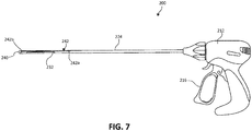
- the dual microwave/RF energy ablation system 210 generally includes a tissue ablation instrument 200 operably coupled to the microwave generator 12, the radiofrequency generator 14, and the surgical suction pump 16.
- the microwave generator 12 generates a microwave signal and outputs it to a microwave antenna 232 of the surgical instrument 200 via a coaxial cable 202.
- the electrosurgical generator 14 generates a radiofrequency signal and outputs it to a monopolar electrode 242 of the surgical instrument 200 via a transmission line 204.
- a return signal, originating from the transmission line 204, may be received by a ground pad 205 coupled to the electrosurgical generator 14.
- the surgical suction pump 16 produces suction and applies the suction to a port 240 located a distal portion of the surgical instrument 200 via a suction tube 206.
- the tissue ablation system 210 may further include a coolant 18 (e.g., saline) and a pump 20 for conveying the coolant to the surgical instrument 200 to cool various components therein during operation.
- a coolant 18 e.g
- the surgical instrument 200 of the tissue ablation system 210 includes a handle portion 212 and a shaft assembly 220 extending distally from the handle portion 212.
- the shaft assembly 220 includes a hollow, elongated body or outer shaft 222 and an outer coating or sheath 224 covering an outer surface of the outer shaft 222.
- the outer sheath 224 is operably coupled to a control 216, such as a button, switch, or trigger, of the handle portion 212.
- the outer sheath 224 in response to an actuation of the control 216, axially moves relative to the handle portion 212 and the outer shaft 222 between a proximal position and a distal position to selectively expose a hook-shaped monopolar electrode 242 of the surgical instrument 200, as will be described in detail below.
- the shaft assembly 220 further includes a coaxial cable 202 that forms the microwave antenna 232 at its terminal end.
- the microwave antenna 232 and its associated components are similar to the microwave antenna 132 described above, and will therefore not be described in further detail herein.
- the monopolar electrode 242 is disposed between an outer surface of the outer shaft 222 and an inner surface of the outer sheath 224, and is electrically coupled to the electrosurgical generator 14.
- the monopolar electrode 242 has a proximal portion 242a in communication with the transmission line 204, and a distal portion 242b extending distally beyond the microwave antenna 232.
- the proximal portion 242a of the monopolar electrode 242 may be mechanically coupled to the control 216 such that an actuation of the control 216 moves the monopolar electrode 242 between proximal and distal positions relative to the outer sheath 224.
- the distal portion 242b of the monopolar electrode 242 may have a hooked configuration for depressing tissue upon contact therewith.
- the distal portion 242b extends at a perpendicular angle relative to the longitudinal axis defined by the outer shaft 222.
- the distal portion 242b of the monopolar electrode 242 may extend at a variety of angles relative to the longitudinal axis of the outer shaft 222, e.g., 0° to 180°.
- the distal portion 242b may assume a helical configuration, a curved configuration, or the like.
- a portion of tissue such as a section of liver tissue "T” may be ablated and resected using the tissue ablation system 210 of the present disclosure.
- tissue ablation system 210 of the present disclosure.
- an edge of the distal portion of the outer shaft 222 may be placed in contact with a surface "S" of the liver tissue "T” to be resected.
- the handle portion 212 is actuated to activate the microwave function of the surgical instrument 200, whereby the microwave generator 12 transmits microwave energy to the microwave antenna 232 via the coaxial cable 202.
- the microwave antenna 232 directs the microwave energy radially outward therefrom and toward the edge of the outer shaft 222 and into the valley formed in the tissue "T.” As the microwave energy is transmitted into the valley of the tissue "T,” the surgical instrument 200 is manipulated to move or slide the edge of the outer shaft 222 along a resection plane "P" of the liver tissue "T,” thereby pre-coagulating the underlying tissue at a depth proportional to the frequency of the microwave energy and the length of time the microwave antenna 232 is activated.
- Movement of the edge of the outer shaft 222 of the surgical instrument 200 along the resection plane "P" is continued until a desired depth and/or width of tissue pre-coagulation is achieved.
- transmission of the microwave energy is deactivated and the outer sheath 224 of the shaft assembly 220 is moved proximally toward the proximal position to expose the distal portion 242b of the monopolar electrode 242.
- the monopolar electrode 242 may be moved distally beyond the outer sheath 224. With the distal portion 242b of the monopolar electrode 242 exposed, the distal portion 242b of the monopolar electrode 242 contacts the tissue surface "S" of the pre-coagulated tissue along the resection plane "P.”
- the control 216 of the handle portion 212 is actuated to activate the radiofrequency function of the surgical instrument 200, whereby the electrosurgical generator 14 transmits radiofrequency energy to the monopolar electrode 242, whereby the radiofrequency energy is directed into the liver tissue "T” to resect the liver tissue "T” along the resection plane "P.”
- the above-noted steps may be repeated to pre-coagulate the tissue "T” at increasingly greater depths until the desired volume of the tissue "T” is pre-coagulated and resected from the remainder of the organ.
- the surgical suction pump 16 may be activated at any point during and/or after the procedure to remove surgical debris and/or surgical smoke via the port 240 of the surgical instrument 200.
- tissue ablation systems are capable of directing microwave and radiofrequency energy into tissue, and may be suitable for use in a variety of procedures and operations.
- the above-described tissue ablation systems may be suitable for utilization with hand-assisted, endoscopic, and laparoscopic surgical procedures.
- the above-described tissue ablation systems may also be suitable for utilization in open surgical applications.
- CT computed tomographic
Landscapes
- Health & Medical Sciences (AREA)
- Surgery (AREA)
- Life Sciences & Earth Sciences (AREA)
- Engineering & Computer Science (AREA)
- Biomedical Technology (AREA)
- Molecular Biology (AREA)
- Nuclear Medicine, Radiotherapy & Molecular Imaging (AREA)
- Veterinary Medicine (AREA)
- Physics & Mathematics (AREA)
- Heart & Thoracic Surgery (AREA)
- Medical Informatics (AREA)
- Otolaryngology (AREA)
- Animal Behavior & Ethology (AREA)
- General Health & Medical Sciences (AREA)
- Public Health (AREA)
- Plasma & Fusion (AREA)
- Electromagnetism (AREA)
- Surgical Instruments (AREA)
Claims (12)
- Chirurgisches Instrument (100) zum Ablatieren von Gewebe, umfassend:einen Griffabschnitt (112); undeine Schaftanordnung (120), die sich von dem Griffabschnitt distal erstreckt und einschließlich:einen äußeren Schaft (122), die einen distalen Abschnitt (122a) aufweist;ein Koaxialkabel (102), das sich durch den äußeren Schaft erstreckt und einen distalen Abschnitt (102b) aufweist, der innerhalb des distalen Abschnitts des äußeren Schafts eingerichtet ist, wobei der distale Abschnitt des Koaxialkabels eine Mikrowellenantenne (132) ausbildet, die konfiguriert ist, um Mikrowellenenergie radial nach außen und durch den äußeren Schaft zu übertragen; undwenigstens eine Elektrode (142a, 142b), die mit dem distalen Abschnitt des äußeren Schafts gekoppelt und konfiguriert ist, um Hochfrequenzenergie zu übertragen, wobei eine Betätigung des chirurgischen Instruments die Übertragungen der Mikrowellenenergie von der Mikrowellenantenne und/oder die Übertragung der Hochfrequenzenergie von der wenigstens einen Elektrode aktiviert;und wobei der äußere Schaft eine Längsachse (X) definiert und dadurch gekennzeichnet ist, dass der distale Abschnitt des äußeren Schafts ein dreieckiges oder keilförmiges Querschnittsprofil in der Ebene senkrecht zu der Längsachse aufweist.
- Chirurgisches Instrument nach Anspruch 1, wobei die wenigstens eine Elektrode von der Mikrowellenantenne distal eingerichtet ist.
- Chirurgisches Instrument nach Anspruch 1, wobei die wenigstens eine Elektrode von der Mikrowellenantenne radial nach außen eingerichtet und nicht mehr mit der Bewegungsrichtung der Mikrowellenenergie ausgerichtet ist, die von der Mikrowellenantenne übertragen wird.
- Chirurgisches Instrument nach Anspruch 1, wobei die wenigstens eine Elektrode ein Paar bipolarer Elektroden (142a, 142b) ist.
- Chirurgisches Instrument nach einem der vorhergehenden Ansprüche, wobei die Schaftanordnung ferner einen Reflektor (136) einschließt, der innerhalb des distalen Abschnitts des äußeren Schafts und um die Mikrowellenantenne herum eingerichtet ist.
- Chirurgisches Instrument nach Anspruch 5, wobei der Reflektor eine halbkreisförmige Form aufweist und konfiguriert ist, um die Übertragung der Mikrowellenenergie auf einen Rand (128) des äußeren Schafts zu lenken, wobei sich der Rand des äußeren Schafts parallel zu einer Längsachse erstreckt, die durch die Schaftanordnung definiert ist.
- Chirurgisches Instrument nach Anspruch 6, wobei die Schaftanordnung ferner einen dielektrischen Bereich (134) einschließt, der innerhalb des distalen Abschnitts des äußeren Schafts eingerichtet ist.
- Chirurgisches Instrument nach Anspruch 7, wobei der Reflektor und ein Paar angrenzender lateraler Seiten (126b, 126c) des äußeren Schafts zusammen einen Hohlraum (139) darin definieren, wobei der dielektrische Bereich den Hohlraum ausfüllt.
- Chirurgisches Instrument nach einem der vorhergehenden Ansprüche, ferner umfassend einen Schlauch (106), der sich durch den äußeren Schaft erstreckt und von der Mikrowellenantenne radial nach außen eingerichtet ist, wobei der Schlauch einen proximalen Abschnitt (106a) aufweist, der konfiguriert ist, um eine Ansaugung aufzunehmen.
- Chirurgisches Instrument nach einem der vorhergehenden Ansprüche, wobei die wenigstens eine Elektrode einen distalen Hakenabschnitt (242b) einschließt, der von der Mikrowellenantenne distal eingerichtet ist.
- Chirurgisches Instrument nach Anspruch 10, wobei die Schaftanordnung ferner eine äußere Hülle (224) einschließt, die um den äußeren Schaft herum eingerichtet und relativ zu dem äußeren Schaft zwischen einer ersten Position, in der der distale Hakenabschnitt innerhalb der Außenhülle eingerichtet ist, und einer zweiten Position, in der der distale Hakenabschnitt von der äußeren Hülle distal eingerichtet ist, axial bewegbar ist.
- Gewebeablationssystem (10), umfassend:einen Mikrowellengenerator (12), der konfiguriert ist, um Mikrowellenenergie zu erzeugen und zu übertragen;einen elektrochirurgischen Generator (14), der konfiguriert ist, um Hochfrequenzenergie zu erzeugen und zu übertragen; undein chirurgisches Instrument nach einem der vorhergehenden Ansprüche.
Applications Claiming Priority (1)
| Application Number | Priority Date | Filing Date | Title |
|---|---|---|---|
| US15/626,867 US10716619B2 (en) | 2017-06-19 | 2017-06-19 | Microwave and radiofrequency energy-transmitting tissue ablation systems |
Publications (2)
| Publication Number | Publication Date |
|---|---|
| EP3417822A1 EP3417822A1 (de) | 2018-12-26 |
| EP3417822B1 true EP3417822B1 (de) | 2021-04-21 |
Family
ID=62705525
Family Applications (1)
| Application Number | Title | Priority Date | Filing Date |
|---|---|---|---|
| EP18178349.9A Active EP3417822B1 (de) | 2017-06-19 | 2018-06-18 | Mikrowellen- und hochfrequenz-energieübertragende gewebeablationssysteme |
Country Status (6)
| Country | Link |
|---|---|
| US (1) | US10716619B2 (de) |
| EP (1) | EP3417822B1 (de) |
| JP (1) | JP7142480B2 (de) |
| CN (1) | CN109124761B (de) |
| AU (1) | AU2018204194A1 (de) |
| CA (1) | CA3008243C (de) |
Families Citing this family (7)
| Publication number | Priority date | Publication date | Assignee | Title |
|---|---|---|---|---|
| WO2021000293A1 (en) * | 2019-07-03 | 2021-01-07 | Covidien Lp | Energy-delivery devices |
| GB2589589A (en) * | 2019-12-03 | 2021-06-09 | Creo Medical Ltd | Electrosurgical instrument |
| CN112932659A (zh) * | 2021-01-26 | 2021-06-11 | 上海优医基微能医疗科技有限公司 | 一种微波消融电极针及其消融系统 |
| CN113974825A (zh) * | 2021-10-29 | 2022-01-28 | 上海美微达医疗科技有限公司 | 带射频针道止血功能的微波消融电极装置及系统和方法 |
| CN116058957B (zh) * | 2021-10-29 | 2025-11-21 | 上海美微达医疗科技有限公司 | 一种具有止血功能的射频消融系统 |
| CN114209419B (zh) * | 2021-12-14 | 2024-07-05 | 上海交通大学医学院附属瑞金医院 | 一种消融治疗设备 |
| CN115778526B (zh) * | 2022-07-11 | 2023-08-29 | 南京康友医疗科技有限公司 | 一种微波、射频和测温一体式消融针 |
Family Cites Families (164)
| Publication number | Priority date | Publication date | Assignee | Title |
|---|---|---|---|---|
| DE390937C (de) | 1922-10-13 | 1924-03-03 | Adolf Erb | Vorrichtung zur Innenbeheizung von Wannenoefen zum Haerten, Anlassen, Gluehen, Vergueten und Schmelzen |
| DE1099658B (de) | 1959-04-29 | 1961-02-16 | Siemens Reiniger Werke Ag | Selbsttaetige Einschaltvorrichtung fuer Hochfrequenzchirurgiegeraete |
| FR1275415A (fr) | 1960-09-26 | 1961-11-10 | Dispositif détecteur de perturbations pour installations électriques, notamment d'électrochirurgie | |
| DE1139927B (de) | 1961-01-03 | 1962-11-22 | Friedrich Laber | Hochfrequenz-Chirurgiegeraet |
| DE1149832C2 (de) | 1961-02-25 | 1977-10-13 | Siemens AG, 1000 Berlin und 8000 München | Hochfrequenz-chirurgieapparat |
| FR1347865A (fr) | 1962-11-22 | 1964-01-04 | Perfectionnements aux appareils de diathermo-coagulation | |
| DE1439302B2 (de) | 1963-10-26 | 1971-05-19 | Siemens AG, 1000 Berlin u 8000 München | Hochfrequenz Chirurgiegerat |
| SU401367A1 (ru) | 1971-10-05 | 1973-10-12 | Тернопольский государственный медицинский институт | Биактивный электрохирургическнп инструмент |
| FR2235669A1 (en) | 1973-07-07 | 1975-01-31 | Lunacek Boris | Gynaecological sterilisation instrument - has hollow electrode protruding from the end of a curved ended tube |
| GB1480736A (en) | 1973-08-23 | 1977-07-20 | Matburn Ltd | Electrodiathermy apparatus |
| FR2251864A1 (en) | 1973-11-21 | 1975-06-13 | Termiflex Corp | Portable input and output unit for connection to a data processor - is basically a calculator with transmitter and receiver |
| DE2407559C3 (de) | 1974-02-16 | 1982-01-21 | Dornier System Gmbh, 7990 Friedrichshafen | Wärmesonde |
| DE2415263A1 (de) | 1974-03-29 | 1975-10-02 | Aesculap Werke Ag | Chirurgische hf-koagulationssonde |
| DE2429021C2 (de) | 1974-06-18 | 1983-12-08 | Erbe Elektromedizin GmbH, 7400 Tübingen | Fernschalteinrichtung für ein HF-Chirurgiegerät |
| FR2276027A1 (fr) | 1974-06-25 | 1976-01-23 | Medical Plastics Inc | Raccordement electrique pour electrode plane |
| DE2460481A1 (de) | 1974-12-20 | 1976-06-24 | Delma Elektro Med App | Elektrodenhandgriff zur handfernschaltung eines hochfrequenz-chirurgiegeraets |
| US4237887A (en) | 1975-01-23 | 1980-12-09 | Valleylab, Inc. | Electrosurgical device |
| DE2504280C3 (de) | 1975-02-01 | 1980-08-28 | Hans Heinrich Prof. Dr. 8035 Gauting Meinke | Vorrichtung zum Schneiden und/oder Koagulieren menschlichen Gewebes mit Hochfrequenzstrom |
| CA1064581A (en) | 1975-06-02 | 1979-10-16 | Stephen W. Andrews | Pulse control circuit and method for electrosurgical units |
| FR2315286A2 (fr) | 1975-06-26 | 1977-01-21 | Lamidey Marcel | Pince a dissequer, hemostatique, haute frequence |
| DE2540968C2 (de) | 1975-09-13 | 1982-12-30 | Erbe Elektromedizin GmbH, 7400 Tübingen | Einrichtung zum Einschalten des Koagulationsstroms einer bipolaren Koagulationspinzette |
| FR2390968A1 (fr) | 1977-05-16 | 1978-12-15 | Skovajsa Joseph | Dispositif de traitement local d'un patient, notamment pour acupuncture ou auriculotherapie |
| SU727201A2 (ru) | 1977-11-02 | 1980-04-15 | Киевский Научно-Исследовательский Институт Нейрохирургии | Электрохирургический аппарат |
| DE2803275C3 (de) | 1978-01-26 | 1980-09-25 | Aesculap-Werke Ag Vormals Jetter & Scheerer, 7200 Tuttlingen | Fernschalteinrichtung zum Schalten eines monopolaren HF-Chirurgiegerätes |
| DE2823291A1 (de) | 1978-05-27 | 1979-11-29 | Rainer Ing Grad Koch | Schaltung zur automatischen einschaltung des hochfrequenzstromes von hochfrequenz-koagulationsgeraeten |
| DE2946728A1 (de) | 1979-11-20 | 1981-05-27 | Erbe Elektromedizin GmbH & Co KG, 7400 Tübingen | Hochfrequenz-chirurgiegeraet |
| USD263020S (en) | 1980-01-22 | 1982-02-16 | Rau Iii David M | Retractable knife |
| JPS56161636A (en) | 1980-05-16 | 1981-12-12 | Tdk Electronics Co Ltd | Slide type variable capacitor |
| USD266842S (en) | 1980-06-27 | 1982-11-09 | Villers Mark W | Phonograph record spacer |
| USD278306S (en) | 1980-06-30 | 1985-04-09 | Mcintosh Lois A | Microwave oven rack |
| JPS5778844A (en) | 1980-11-04 | 1982-05-17 | Kogyo Gijutsuin | Lasre knife |
| DE3045996A1 (de) | 1980-12-05 | 1982-07-08 | Medic Eschmann Handelsgesellschaft für medizinische Instrumente mbH, 2000 Hamburg | Elektro-chirurgiegeraet |
| FR2502935B1 (fr) | 1981-03-31 | 1985-10-04 | Dolley Roger | Procede et dispositif de controle de la coagulation de tissus a l'aide d'un courant a haute frequence |
| DE3120102A1 (de) | 1981-05-20 | 1982-12-09 | F.L. Fischer GmbH & Co, 7800 Freiburg | Anordnung zur hochfrequenzkoagulation von eiweiss fuer chirurgische zwecke |
| FR2517953A1 (fr) | 1981-12-10 | 1983-06-17 | Alvar Electronic | Appareil diaphanometre et son procede d'utilisation |
| JPS5958933A (ja) | 1982-09-28 | 1984-04-04 | Nec Corp | 双方向バ−スト形デイジタル伝送の受信回路 |
| US4583556A (en) | 1982-12-13 | 1986-04-22 | M/A-Com, Inc. | Microwave applicator/receiver apparatus |
| US4601296A (en) * | 1983-10-07 | 1986-07-22 | Yeda Research And Development Co., Ltd. | Hyperthermia apparatus |
| FR2573301B3 (fr) | 1984-11-16 | 1987-04-30 | Lamidey Gilles | Pince chirurgicale et son appareillage de commande et de controle |
| DE3510586A1 (de) | 1985-03-23 | 1986-10-02 | Erbe Elektromedizin GmbH, 7400 Tübingen | Kontrolleinrichtung fuer ein hochfrequenz-chirurgiegeraet |
| USD295893S (en) | 1985-09-25 | 1988-05-24 | Acme United Corporation | Disposable surgical clamp |
| USD295894S (en) | 1985-09-26 | 1988-05-24 | Acme United Corporation | Disposable surgical scissors |
| DE3604823C2 (de) | 1986-02-15 | 1995-06-01 | Lindenmeier Heinz | Hochfrequenzgenerator mit automatischer Leistungsregelung für die Hochfrequenzchirurgie |
| EP0246350A1 (de) | 1986-05-23 | 1987-11-25 | Erbe Elektromedizin GmbH. | Koagulationselektrode |
| DE3711511C1 (de) | 1987-04-04 | 1988-06-30 | Hartmann & Braun Ag | Verfahren zur Bestimmung der Gaskonzentrationen in einem Gasgemisch und Sensor zur Messung der Waermeleitfaehigkeit |
| DE8712328U1 (de) | 1987-09-11 | 1988-02-18 | Jakoubek, Franz, 7201 Emmingen-Liptingen | Endoskopiezange |
| DE3904558C2 (de) | 1989-02-15 | 1997-09-18 | Lindenmeier Heinz | Automatisch leistungsgeregelter Hochfrequenzgenerator für die Hochfrequenz-Chirurgie |
| DE3942998C2 (de) | 1989-12-27 | 1998-11-26 | Delma Elektro Med App | Elektrochirurgisches Hochfrequenzgerät |
| JP2806511B2 (ja) | 1990-07-31 | 1998-09-30 | 松下電工株式会社 | 合金系焼結体の製法 |
| JP2951418B2 (ja) | 1991-02-08 | 1999-09-20 | トキコ株式会社 | 試料液成分分析装置 |
| DE4122050C2 (de) | 1991-07-03 | 1996-05-30 | Gore W L & Ass Gmbh | Antennenanordnung mit Zuleitung zur medizinischen Wärmeapplikation in Körperhohlräumen |
| JPH058933A (ja) | 1991-07-05 | 1993-01-19 | Furukawa Electric Co Ltd:The | 巻取幅調整型巻取枠装置 |
| DE4238263A1 (en) | 1991-11-15 | 1993-05-19 | Minnesota Mining & Mfg | Adhesive comprising hydrogel and crosslinked polyvinyl:lactam - is used in electrodes for biomedical application providing low impedance and good mechanical properties when water and/or moisture is absorbed from skin |
| DE4205213A1 (de) | 1992-02-20 | 1993-08-26 | Delma Elektro Med App | Hochfrequenzchirurgiegeraet |
| FR2687786B1 (fr) | 1992-02-26 | 1994-05-06 | Pechiney Recherche | Mesure de la resistivite electrique et de la conductivite thermique a haute temperature de produits refractaires. |
| USD354218S (en) | 1992-10-01 | 1995-01-10 | Fiberslab Pty Limited | Spacer for use in concrete construction |
| DE4303882C2 (de) | 1993-02-10 | 1995-02-09 | Kernforschungsz Karlsruhe | Kombinationsinstrument zum Trennen und Koagulieren für die minimal invasive Chirurgie |
| GB9309142D0 (en) | 1993-05-04 | 1993-06-16 | Gyrus Medical Ltd | Laparoscopic instrument |
| FR2711066B1 (fr) | 1993-10-15 | 1995-12-01 | Sadis Bruker Spectrospin | Antenne pour le chauffage de tissus par micro-ondes et sonde comportant une ou plusieurs de ces antennes. |
| GB9322464D0 (en) | 1993-11-01 | 1993-12-22 | Gyrus Medical Ltd | Electrosurgical apparatus |
| DE4339049C2 (de) | 1993-11-16 | 2001-06-28 | Erbe Elektromedizin | Einrichtung zur Konfiguration chirurgischer Systeme |
| GB9413070D0 (en) | 1994-06-29 | 1994-08-17 | Gyrus Medical Ltd | Electrosurgical apparatus |
| GB9425781D0 (en) | 1994-12-21 | 1995-02-22 | Gyrus Medical Ltd | Electrosurgical instrument |
| JP3500228B2 (ja) | 1995-06-21 | 2004-02-23 | オリンパス株式会社 | 内視鏡用処置具挿抜装置 |
| US6293942B1 (en) | 1995-06-23 | 2001-09-25 | Gyrus Medical Limited | Electrosurgical generator method |
| JP3782495B2 (ja) | 1995-10-27 | 2006-06-07 | アルフレッサファーマ株式会社 | マイクロ波手術装置 |
| DE19608716C1 (de) | 1996-03-06 | 1997-04-17 | Aesculap Ag | Bipolares chirurgisches Faßinstrument |
| US5800494A (en) | 1996-08-20 | 1998-09-01 | Fidus Medical Technology Corporation | Microwave ablation catheters having antennas with distal fire capabilities |
| DE29616210U1 (de) | 1996-09-18 | 1996-11-14 | Olympus Winter & Ibe Gmbh, 22045 Hamburg | Handhabe für chirurgische Instrumente |
| US6355034B2 (en) * | 1996-09-20 | 2002-03-12 | Ioan Cosmescu | Multifunctional telescopic monopolar/bipolar surgical device and method therefor |
| DE19643127A1 (de) | 1996-10-18 | 1998-04-23 | Berchtold Gmbh & Co Geb | Hochfrequenzchirurgiegerät und Verfahren zu dessen Betrieb |
| US5923475A (en) | 1996-11-27 | 1999-07-13 | Eastman Kodak Company | Laser printer using a fly's eye integrator |
| DE19717411A1 (de) | 1997-04-25 | 1998-11-05 | Aesculap Ag & Co Kg | Verfahren und Vorrichtung zur Überwachung der thermischen Belastung des Gewebes eines Patienten |
| DE59712260D1 (de) | 1997-06-06 | 2005-05-12 | Endress & Hauser Gmbh & Co Kg | Mit Mikrowellen arbeitendes Füllstandsmessgerät |
| DE19751108A1 (de) | 1997-11-18 | 1999-05-20 | Beger Frank Michael Dipl Desig | Elektrochirurgisches Operationswerkzeug |
| EP0923907A1 (de) | 1997-12-19 | 1999-06-23 | Gyrus Medical Limited | Elektrochirurgisches Instrument |
| DE19801173C1 (de) | 1998-01-15 | 1999-07-15 | Kendall Med Erzeugnisse Gmbh | Klemmverbinder für Filmelektroden |
| DE19848540A1 (de) | 1998-10-21 | 2000-05-25 | Reinhard Kalfhaus | Schaltungsanordnung und Verfahren zum Betreiben eines Wechselrichters |
| USD449886S1 (en) | 1998-10-23 | 2001-10-30 | Sherwood Services Ag | Forceps with disposable electrode |
| USD425201S (en) | 1998-10-23 | 2000-05-16 | Sherwood Services Ag | Disposable electrode assembly |
| USD424694S (en) | 1998-10-23 | 2000-05-09 | Sherwood Services Ag | Forceps |
| ATE507788T1 (de) | 1998-12-18 | 2011-05-15 | Celon Ag Medical Instruments | Elektrodenanordnung für ein chirurgisches instrument zur elektrothermischen koagulation im gewebe |
| USD424693S (en) | 1999-04-08 | 2000-05-09 | Pruter Rick L | Needle guide for attachment to an ultrasound transducer probe |
| GB9911956D0 (en) | 1999-05-21 | 1999-07-21 | Gyrus Medical Ltd | Electrosurgery system and method |
| GB9911954D0 (en) | 1999-05-21 | 1999-07-21 | Gyrus Medical Ltd | Electrosurgery system and instrument |
| GB9912627D0 (en) | 1999-05-28 | 1999-07-28 | Gyrus Medical Ltd | An electrosurgical instrument |
| GB9912625D0 (en) | 1999-05-28 | 1999-07-28 | Gyrus Medical Ltd | An electrosurgical generator and system |
| GB9913652D0 (en) | 1999-06-11 | 1999-08-11 | Gyrus Medical Ltd | An electrosurgical generator |
| JP2001003776A (ja) | 1999-06-22 | 2001-01-09 | Mitsubishi Electric Corp | 自動変速機制御装置 |
| JP2001037775A (ja) | 1999-07-26 | 2001-02-13 | Olympus Optical Co Ltd | 治療装置 |
| JP2001231870A (ja) | 2000-02-23 | 2001-08-28 | Olympus Optical Co Ltd | 加温治療装置 |
| US6471696B1 (en) * | 2000-04-12 | 2002-10-29 | Afx, Inc. | Microwave ablation instrument with a directional radiation pattern |
| DE10027727C1 (de) | 2000-06-03 | 2001-12-06 | Aesculap Ag & Co Kg | Scheren- oder zangenförmiges chirurgisches Instrument |
| ITPI20010006A1 (it) | 2001-01-31 | 2002-07-31 | Cnr Consiglio Naz Delle Ricer | Antenna interstiziale con choke miniaturizzato per applicazioni di ipertemia a microonde in medicina e chirurgia |
| JP4346826B2 (ja) | 2001-02-28 | 2009-10-21 | 瑞穂医科工業株式会社 | 携帯型電気手術器、それを備えた携帯型電気手術器システムおよび携帯型電気手術器の制御方法 |
| USD457958S1 (en) | 2001-04-06 | 2002-05-28 | Sherwood Services Ag | Vessel sealer and divider |
| USD457959S1 (en) | 2001-04-06 | 2002-05-28 | Sherwood Services Ag | Vessel sealer |
| DE10217281A1 (de) | 2002-04-12 | 2003-10-23 | Laser & Med Tech Gmbh | Verfahren und Vorrichtung zur Lokalisation intrakorporaler, flexibler Instrumente mit Ultraschall |
| DE10224154A1 (de) | 2002-05-27 | 2003-12-18 | Celon Ag Medical Instruments | Vorrichtung zum elektrochirurgischen Veröden von Körpergewebe |
| USD487039S1 (en) | 2002-11-27 | 2004-02-24 | Robert Bosch Corporation | Spacer |
| DE10310765A1 (de) | 2003-03-12 | 2004-09-30 | Dornier Medtech Systems Gmbh | Sonde und Vorrichtung für eine Thermotherapie |
| USD499181S1 (en) | 2003-05-15 | 2004-11-30 | Sherwood Services Ag | Handle for a vessel sealer and divider |
| USD496997S1 (en) | 2003-05-15 | 2004-10-05 | Sherwood Services Ag | Vessel sealer and divider |
| DE10328514B3 (de) | 2003-06-20 | 2005-03-03 | Aesculap Ag & Co. Kg | Chirurgisches Instrument |
| US7311703B2 (en) | 2003-07-18 | 2007-12-25 | Vivant Medical, Inc. | Devices and methods for cooling microwave antennas |
| FR2862813B1 (fr) | 2003-11-20 | 2006-06-02 | Pellenc Sa | Procede de chargement equilibre d'une batterie lithium-ion ou lithium polymere |
| FR2864439B1 (fr) | 2003-12-30 | 2010-12-03 | Image Guided Therapy | Dispositif de traitement d'un volume de tissu biologique par hyperthermie localisee |
| USD541938S1 (en) | 2004-04-09 | 2007-05-01 | Sherwood Services Ag | Open vessel sealer with mechanical cutter |
| US7101369B2 (en) | 2004-04-29 | 2006-09-05 | Wisconsin Alumni Research Foundation | Triaxial antenna for microwave tissue ablation |
| DE102004022206B4 (de) | 2004-05-04 | 2006-05-11 | Bundesrepublik Deutschland, vertr. d. d. Bundesministerium für Wirtschaft und Arbeit, dieses vertr. d. d. Präsidenten der Physikalisch-Technischen Bundesanstalt | Sensor und Sensoranordnung zur Messung der Wärmeleitfähigkeit einer Probe |
| USD533942S1 (en) | 2004-06-30 | 2006-12-19 | Sherwood Services Ag | Open vessel sealer with mechanical cutter |
| USD535027S1 (en) | 2004-10-06 | 2007-01-09 | Sherwood Services Ag | Low profile vessel sealing and cutting mechanism |
| USD525361S1 (en) | 2004-10-06 | 2006-07-18 | Sherwood Services Ag | Hemostat style elongated dissecting and dividing instrument |
| USD531311S1 (en) | 2004-10-06 | 2006-10-31 | Sherwood Services Ag | Pistol grip style elongated dissecting and dividing instrument |
| USD541418S1 (en) | 2004-10-06 | 2007-04-24 | Sherwood Services Ag | Lung sealing device |
| USD564662S1 (en) | 2004-10-13 | 2008-03-18 | Sherwood Services Ag | Hourglass-shaped knife for electrosurgical forceps |
| SE0403133D0 (sv) | 2004-12-22 | 2004-12-22 | Ericsson Telefon Ab L M | A method and arrangement for providing communication group information to a client |
| USD576932S1 (en) | 2005-03-01 | 2008-09-16 | Robert Bosch Gmbh | Spacer |
| US7797056B2 (en) * | 2005-09-06 | 2010-09-14 | Nmt Medical, Inc. | Removable intracardiac RF device |
| DE202005015147U1 (de) | 2005-09-26 | 2006-02-09 | Health & Life Co., Ltd., Chung-Ho | Biosensor-Teststreifen mit Identifizierfunktion |
| US8103356B2 (en) * | 2006-05-23 | 2012-01-24 | Vertech, Inc. | High frequency epidural neuromodulation catheter without needle for effectuating RF treatment |
| WO2008011351A2 (en) * | 2006-07-19 | 2008-01-24 | Boston Scientific Scimed, Inc. | Apparatus for tissue resection |
| EP1897506B1 (de) * | 2006-09-08 | 2010-03-03 | Ethicon Endo-Surgery, Inc. | Chirurgisches Instrument zur kontrollierten Durchführung von Myotomien |
| GB0620063D0 (en) * | 2006-10-10 | 2006-11-22 | Medical Device Innovations Ltd | Needle structure and method of performing needle biopsies |
| JP2010508124A (ja) * | 2006-11-01 | 2010-03-18 | ボビー メディカル,コーポレイション | 導電流体を送り出すための多孔電極を有する双極除去プローブ |
| JP4618241B2 (ja) | 2006-12-13 | 2011-01-26 | 株式会社村田製作所 | 同軸プローブ装置 |
| GB0702763D0 (en) | 2007-02-13 | 2007-03-21 | Skype Ltd | Messaging system and method |
| US8747398B2 (en) | 2007-09-13 | 2014-06-10 | Covidien Lp | Frequency tuning in a microwave electrosurgical system |
| JP4725808B2 (ja) * | 2007-11-14 | 2011-07-13 | 有限会社リバー精工 | 内視鏡用フック型高周波処置具 |
| USD606203S1 (en) | 2008-07-04 | 2009-12-15 | Cambridge Temperature Concepts, Ltd. | Hand-held device |
| USD594736S1 (en) | 2008-08-13 | 2009-06-23 | Saint-Gobain Ceramics & Plastics, Inc. | Spacer support |
| US9173706B2 (en) | 2008-08-25 | 2015-11-03 | Covidien Lp | Dual-band dipole microwave ablation antenna |
| WO2010035831A1 (ja) | 2008-09-29 | 2010-04-01 | 京セラ株式会社 | 切削インサート、切削工具、およびそれらを用いる切削方法 |
| US20140358140A1 (en) | 2008-10-21 | 2014-12-04 | Microcube, Llc | Microwave treatment devices and methods |
| EP2349452B1 (de) * | 2008-10-21 | 2016-05-11 | Microcube, LLC | Vorrichtungen für mikrowellenbehandlung |
| USD594737S1 (en) | 2008-10-28 | 2009-06-23 | Mmi Management Services Lp | Rebar chair |
| DE102009015699A1 (de) | 2008-10-30 | 2010-05-06 | Rohde & Schwarz Gmbh & Co. Kg | Breitband-Antenne |
| US20100286687A1 (en) * | 2009-05-06 | 2010-11-11 | Ian Feldberg | Dual Energy Therapy Needle |
| US8235981B2 (en) | 2009-06-02 | 2012-08-07 | Vivant Medical, Inc. | Electrosurgical devices with directional radiation pattern |
| USD634010S1 (en) | 2009-08-05 | 2011-03-08 | Vivant Medical, Inc. | Medical device indicator guide |
| USD613412S1 (en) | 2009-08-06 | 2010-04-06 | Vivant Medical, Inc. | Vented microwave spacer |
| US8069553B2 (en) | 2009-09-09 | 2011-12-06 | Vivant Medical, Inc. | Method for constructing a dipole antenna |
| US8764744B2 (en) | 2010-01-25 | 2014-07-01 | Covidien Lp | System for monitoring ablation size |
| US8728067B2 (en) | 2010-03-08 | 2014-05-20 | Covidien Lp | Microwave antenna probe having a deployable ground plane |
| US8740893B2 (en) | 2010-06-30 | 2014-06-03 | Covidien Lp | Adjustable tuning of a dielectrically loaded loop antenna |
| US8690866B2 (en) | 2010-08-23 | 2014-04-08 | Covidien Lp | Ablation devices utilizing exothermic chemical reactions, system including same, and methods of ablating tissue using same |
| JP2012050758A (ja) * | 2010-09-03 | 2012-03-15 | Hoya Corp | 可撓性内視鏡用フック状高周波ナイフ |
| KR20120055063A (ko) | 2010-11-23 | 2012-05-31 | 김상훈 | 어린이 모래놀이터의 모래 살균 방법 |
| GB201021032D0 (en) * | 2010-12-10 | 2011-01-26 | Creo Medical Ltd | Electrosurgical apparatus |
| US8974450B2 (en) | 2011-02-03 | 2015-03-10 | Covidien Lp | System and method for ablation procedure monitoring using electrodes |
| US9579150B2 (en) * | 2011-04-08 | 2017-02-28 | Covidien Lp | Microwave ablation instrument with interchangeable antenna probe |
| AU2015201912B2 (en) * | 2011-04-08 | 2016-12-15 | Covidien Lp | Microwave tissue dissection and coagulation |
| US8745846B2 (en) * | 2011-09-20 | 2014-06-10 | Covidien Lp | Method of manufacturing handheld medical devices including microwave amplifier unit |
| USD681810S1 (en) | 2012-03-05 | 2013-05-07 | Covidien Lp | Ergonomic handle for ablation device |
| US8906008B2 (en) | 2012-05-22 | 2014-12-09 | Covidien Lp | Electrosurgical instrument |
| US20130324910A1 (en) | 2012-05-31 | 2013-12-05 | Covidien Lp | Ablation device with drug delivery component and biopsy tissue-sampling component |
| US10314649B2 (en) * | 2012-08-02 | 2019-06-11 | Ethicon Endo-Surgery, Inc. | Flexible expandable electrode and method of intraluminal delivery of pulsed power |
| US11123130B2 (en) * | 2013-03-15 | 2021-09-21 | Charles Somers Living Trust | RF tissue ablation devices and methods of using the same |
| US20140276200A1 (en) * | 2013-03-15 | 2014-09-18 | Covidien Lp | Microwave energy-delivery device and system |
| GB201308558D0 (en) * | 2013-05-13 | 2013-06-19 | Creo Medical Ltd | Electrosurgical apparatus |
| US9814844B2 (en) | 2013-08-27 | 2017-11-14 | Covidien Lp | Drug-delivery cannula assembly |
| US11134978B2 (en) * | 2016-01-15 | 2021-10-05 | Cilag Gmbh International | Modular battery powered handheld surgical instrument with self-diagnosing control switches for reusable handle assembly |
| US11058487B2 (en) * | 2017-03-09 | 2021-07-13 | Wisconsin Alumni Research Foundation | Microwave ablation antenna system with reflector and slot |
| GB201705171D0 (en) * | 2017-03-30 | 2017-05-17 | Creo Medical Ltd | Elecrosurgical instrument |
-
2017
- 2017-06-19 US US15/626,867 patent/US10716619B2/en active Active
-
2018
- 2018-06-13 AU AU2018204194A patent/AU2018204194A1/en not_active Abandoned
- 2018-06-14 CA CA3008243A patent/CA3008243C/en not_active Expired - Fee Related
- 2018-06-18 EP EP18178349.9A patent/EP3417822B1/de active Active
- 2018-06-19 CN CN201810628224.5A patent/CN109124761B/zh not_active Expired - Fee Related
- 2018-06-19 JP JP2018115958A patent/JP7142480B2/ja active Active
Non-Patent Citations (1)
| Title |
|---|
| None * |
Also Published As
| Publication number | Publication date |
|---|---|
| AU2018204194A1 (en) | 2019-01-17 |
| CN109124761B (zh) | 2021-06-04 |
| JP7142480B2 (ja) | 2022-09-27 |
| CN109124761A (zh) | 2019-01-04 |
| JP2019000649A (ja) | 2019-01-10 |
| CA3008243C (en) | 2021-06-22 |
| US20180360529A1 (en) | 2018-12-20 |
| CA3008243A1 (en) | 2018-12-19 |
| US10716619B2 (en) | 2020-07-21 |
| EP3417822A1 (de) | 2018-12-26 |
Similar Documents
| Publication | Publication Date | Title |
|---|---|---|
| CA3008243C (en) | Microwave and radiofrequency energy-transmitting tissue ablation systems | |
| US9925002B2 (en) | Articulating ablation device and method | |
| JP6464230B2 (ja) | 柔軟な流体冷却シャフトを備えたエネルギー伝達装置、それと共に使用するのに適した流入/流出接合部およびそれらを含むシステム | |
| US8262703B2 (en) | Medical device including member that deploys in a spiral-like configuration and method | |
| KR102359545B1 (ko) | Rf 에너지와 마이크로파 에너지를 전달하기 위한 전기수술 프로브 | |
| US9949794B2 (en) | Microwave ablation devices including expandable antennas and methods of use | |
| EP2508144B1 (de) | Mikrowellen-Gewebesezierung und -koagulation | |
| JP2018192297A (ja) | 柔軟な流体冷却シャフトを備えたエネルギー伝達装置、それと共に使用するのに適した流入/流出接合部およびそれらを含むシステム | |
| JP2011200649A (ja) | 格納式ブレードを有するマイクロ波表面凝固装置 | |
| WO2006138382A2 (en) | Microwave tissue resection tool | |
| WO2016089887A1 (en) | High-efficiency, directional microwave ablation antenna | |
| KR20200042442A (ko) | Rf 및/또는 마이크로파 에너지를 생물학적 조직에 전달하기 위한 전기수술 장치 | |
| EP4031047B1 (de) | Elektrochirurgische vorrichtung zur behandlung von biologischem gewebe mit mikrowellenenergie | |
| JP7492771B2 (ja) | 電気手術器具 | |
| JP2010162300A (ja) | 関節運動する切除デバイスおよび方法 | |
| HK40073264A (en) | Electrosurgical instrument |
Legal Events
| Date | Code | Title | Description |
|---|---|---|---|
| PUAI | Public reference made under article 153(3) epc to a published international application that has entered the european phase |
Free format text: ORIGINAL CODE: 0009012 |
|
| STAA | Information on the status of an ep patent application or granted ep patent |
Free format text: STATUS: REQUEST FOR EXAMINATION WAS MADE |
|
| 17P | Request for examination filed |
Effective date: 20180618 |
|
| AK | Designated contracting states |
Kind code of ref document: A1 Designated state(s): AL AT BE BG CH CY CZ DE DK EE ES FI FR GB GR HR HU IE IS IT LI LT LU LV MC MK MT NL NO PL PT RO RS SE SI SK SM TR |
|
| AX | Request for extension of the european patent |
Extension state: BA ME |
|
| RBV | Designated contracting states (corrected) |
Designated state(s): AL AT BE BG CH CY CZ DE DK EE ES FI FR GB GR HR HU IE IS IT LI LT LU LV MC MK MT NL NO PL PT RO RS SE SI SK SM TR |
|
| GRAP | Despatch of communication of intention to grant a patent |
Free format text: ORIGINAL CODE: EPIDOSNIGR1 |
|
| STAA | Information on the status of an ep patent application or granted ep patent |
Free format text: STATUS: GRANT OF PATENT IS INTENDED |
|
| INTG | Intention to grant announced |
Effective date: 20201116 |
|
| GRAS | Grant fee paid |
Free format text: ORIGINAL CODE: EPIDOSNIGR3 |
|
| GRAA | (expected) grant |
Free format text: ORIGINAL CODE: 0009210 |
|
| STAA | Information on the status of an ep patent application or granted ep patent |
Free format text: STATUS: THE PATENT HAS BEEN GRANTED |
|
| AK | Designated contracting states |
Kind code of ref document: B1 Designated state(s): AL AT BE BG CH CY CZ DE DK EE ES FI FR GB GR HR HU IE IS IT LI LT LU LV MC MK MT NL NO PL PT RO RS SE SI SK SM TR |
|
| REG | Reference to a national code |
Ref country code: GB Ref legal event code: FG4D |
|
| REG | Reference to a national code |
Ref country code: CH Ref legal event code: EP |
|
| REG | Reference to a national code |
Ref country code: DE Ref legal event code: R096 Ref document number: 602018015730 Country of ref document: DE Ref country code: IE Ref legal event code: FG4D |
|
| REG | Reference to a national code |
Ref country code: AT Ref legal event code: REF Ref document number: 1383821 Country of ref document: AT Kind code of ref document: T Effective date: 20210515 |
|
| REG | Reference to a national code |
Ref country code: LT Ref legal event code: MG9D |
|
| REG | Reference to a national code |
Ref country code: AT Ref legal event code: MK05 Ref document number: 1383821 Country of ref document: AT Kind code of ref document: T Effective date: 20210421 |
|
| REG | Reference to a national code |
Ref country code: NL Ref legal event code: MP Effective date: 20210421 |
|
| PG25 | Lapsed in a contracting state [announced via postgrant information from national office to epo] |
Ref country code: NL Free format text: LAPSE BECAUSE OF FAILURE TO SUBMIT A TRANSLATION OF THE DESCRIPTION OR TO PAY THE FEE WITHIN THE PRESCRIBED TIME-LIMIT Effective date: 20210421 Ref country code: AT Free format text: LAPSE BECAUSE OF FAILURE TO SUBMIT A TRANSLATION OF THE DESCRIPTION OR TO PAY THE FEE WITHIN THE PRESCRIBED TIME-LIMIT Effective date: 20210421 Ref country code: BG Free format text: LAPSE BECAUSE OF FAILURE TO SUBMIT A TRANSLATION OF THE DESCRIPTION OR TO PAY THE FEE WITHIN THE PRESCRIBED TIME-LIMIT Effective date: 20210721 Ref country code: HR Free format text: LAPSE BECAUSE OF FAILURE TO SUBMIT A TRANSLATION OF THE DESCRIPTION OR TO PAY THE FEE WITHIN THE PRESCRIBED TIME-LIMIT Effective date: 20210421 Ref country code: LT Free format text: LAPSE BECAUSE OF FAILURE TO SUBMIT A TRANSLATION OF THE DESCRIPTION OR TO PAY THE FEE WITHIN THE PRESCRIBED TIME-LIMIT Effective date: 20210421 Ref country code: FI Free format text: LAPSE BECAUSE OF FAILURE TO SUBMIT A TRANSLATION OF THE DESCRIPTION OR TO PAY THE FEE WITHIN THE PRESCRIBED TIME-LIMIT Effective date: 20210421 |
|
| PG25 | Lapsed in a contracting state [announced via postgrant information from national office to epo] |
Ref country code: IS Free format text: LAPSE BECAUSE OF FAILURE TO SUBMIT A TRANSLATION OF THE DESCRIPTION OR TO PAY THE FEE WITHIN THE PRESCRIBED TIME-LIMIT Effective date: 20210821 Ref country code: GR Free format text: LAPSE BECAUSE OF FAILURE TO SUBMIT A TRANSLATION OF THE DESCRIPTION OR TO PAY THE FEE WITHIN THE PRESCRIBED TIME-LIMIT Effective date: 20210722 Ref country code: NO Free format text: LAPSE BECAUSE OF FAILURE TO SUBMIT A TRANSLATION OF THE DESCRIPTION OR TO PAY THE FEE WITHIN THE PRESCRIBED TIME-LIMIT Effective date: 20210721 Ref country code: PT Free format text: LAPSE BECAUSE OF FAILURE TO SUBMIT A TRANSLATION OF THE DESCRIPTION OR TO PAY THE FEE WITHIN THE PRESCRIBED TIME-LIMIT Effective date: 20210823 Ref country code: PL Free format text: LAPSE BECAUSE OF FAILURE TO SUBMIT A TRANSLATION OF THE DESCRIPTION OR TO PAY THE FEE WITHIN THE PRESCRIBED TIME-LIMIT Effective date: 20210421 Ref country code: LV Free format text: LAPSE BECAUSE OF FAILURE TO SUBMIT A TRANSLATION OF THE DESCRIPTION OR TO PAY THE FEE WITHIN THE PRESCRIBED TIME-LIMIT Effective date: 20210421 Ref country code: RS Free format text: LAPSE BECAUSE OF FAILURE TO SUBMIT A TRANSLATION OF THE DESCRIPTION OR TO PAY THE FEE WITHIN THE PRESCRIBED TIME-LIMIT Effective date: 20210421 Ref country code: SE Free format text: LAPSE BECAUSE OF FAILURE TO SUBMIT A TRANSLATION OF THE DESCRIPTION OR TO PAY THE FEE WITHIN THE PRESCRIBED TIME-LIMIT Effective date: 20210421 |
|
| REG | Reference to a national code |
Ref country code: DE Ref legal event code: R097 Ref document number: 602018015730 Country of ref document: DE |
|
| PG25 | Lapsed in a contracting state [announced via postgrant information from national office to epo] |
Ref country code: RO Free format text: LAPSE BECAUSE OF FAILURE TO SUBMIT A TRANSLATION OF THE DESCRIPTION OR TO PAY THE FEE WITHIN THE PRESCRIBED TIME-LIMIT Effective date: 20210421 Ref country code: DK Free format text: LAPSE BECAUSE OF FAILURE TO SUBMIT A TRANSLATION OF THE DESCRIPTION OR TO PAY THE FEE WITHIN THE PRESCRIBED TIME-LIMIT Effective date: 20210421 Ref country code: CZ Free format text: LAPSE BECAUSE OF FAILURE TO SUBMIT A TRANSLATION OF THE DESCRIPTION OR TO PAY THE FEE WITHIN THE PRESCRIBED TIME-LIMIT Effective date: 20210421 Ref country code: MC Free format text: LAPSE BECAUSE OF FAILURE TO SUBMIT A TRANSLATION OF THE DESCRIPTION OR TO PAY THE FEE WITHIN THE PRESCRIBED TIME-LIMIT Effective date: 20210421 Ref country code: SM Free format text: LAPSE BECAUSE OF FAILURE TO SUBMIT A TRANSLATION OF THE DESCRIPTION OR TO PAY THE FEE WITHIN THE PRESCRIBED TIME-LIMIT Effective date: 20210421 Ref country code: SK Free format text: LAPSE BECAUSE OF FAILURE TO SUBMIT A TRANSLATION OF THE DESCRIPTION OR TO PAY THE FEE WITHIN THE PRESCRIBED TIME-LIMIT Effective date: 20210421 Ref country code: ES Free format text: LAPSE BECAUSE OF FAILURE TO SUBMIT A TRANSLATION OF THE DESCRIPTION OR TO PAY THE FEE WITHIN THE PRESCRIBED TIME-LIMIT Effective date: 20210421 Ref country code: EE Free format text: LAPSE BECAUSE OF FAILURE TO SUBMIT A TRANSLATION OF THE DESCRIPTION OR TO PAY THE FEE WITHIN THE PRESCRIBED TIME-LIMIT Effective date: 20210421 |
|
| REG | Reference to a national code |
Ref country code: CH Ref legal event code: PL |
|
| PLBE | No opposition filed within time limit |
Free format text: ORIGINAL CODE: 0009261 |
|
| STAA | Information on the status of an ep patent application or granted ep patent |
Free format text: STATUS: NO OPPOSITION FILED WITHIN TIME LIMIT |
|
| REG | Reference to a national code |
Ref country code: BE Ref legal event code: MM Effective date: 20210630 |
|
| 26N | No opposition filed |
Effective date: 20220124 |
|
| PG25 | Lapsed in a contracting state [announced via postgrant information from national office to epo] |
Ref country code: LU Free format text: LAPSE BECAUSE OF NON-PAYMENT OF DUE FEES Effective date: 20210618 |
|
| PG25 | Lapsed in a contracting state [announced via postgrant information from national office to epo] |
Ref country code: LI Free format text: LAPSE BECAUSE OF NON-PAYMENT OF DUE FEES Effective date: 20210630 Ref country code: IE Free format text: LAPSE BECAUSE OF NON-PAYMENT OF DUE FEES Effective date: 20210618 Ref country code: CH Free format text: LAPSE BECAUSE OF NON-PAYMENT OF DUE FEES Effective date: 20210630 |
|
| PG25 | Lapsed in a contracting state [announced via postgrant information from national office to epo] |
Ref country code: IS Free format text: LAPSE BECAUSE OF FAILURE TO SUBMIT A TRANSLATION OF THE DESCRIPTION OR TO PAY THE FEE WITHIN THE PRESCRIBED TIME-LIMIT Effective date: 20210821 Ref country code: AL Free format text: LAPSE BECAUSE OF FAILURE TO SUBMIT A TRANSLATION OF THE DESCRIPTION OR TO PAY THE FEE WITHIN THE PRESCRIBED TIME-LIMIT Effective date: 20210421 |
|
| PG25 | Lapsed in a contracting state [announced via postgrant information from national office to epo] |
Ref country code: IT Free format text: LAPSE BECAUSE OF FAILURE TO SUBMIT A TRANSLATION OF THE DESCRIPTION OR TO PAY THE FEE WITHIN THE PRESCRIBED TIME-LIMIT Effective date: 20210421 Ref country code: BE Free format text: LAPSE BECAUSE OF NON-PAYMENT OF DUE FEES Effective date: 20210630 |
|
| PG25 | Lapsed in a contracting state [announced via postgrant information from national office to epo] |
Ref country code: CY Free format text: LAPSE BECAUSE OF FAILURE TO SUBMIT A TRANSLATION OF THE DESCRIPTION OR TO PAY THE FEE WITHIN THE PRESCRIBED TIME-LIMIT Effective date: 20210421 |
|
| PG25 | Lapsed in a contracting state [announced via postgrant information from national office to epo] |
Ref country code: HU Free format text: LAPSE BECAUSE OF FAILURE TO SUBMIT A TRANSLATION OF THE DESCRIPTION OR TO PAY THE FEE WITHIN THE PRESCRIBED TIME-LIMIT; INVALID AB INITIO Effective date: 20180618 |
|
| PGFP | Annual fee paid to national office [announced via postgrant information from national office to epo] |
Ref country code: FR Payment date: 20230524 Year of fee payment: 6 Ref country code: DE Payment date: 20230523 Year of fee payment: 6 |
|
| PGFP | Annual fee paid to national office [announced via postgrant information from national office to epo] |
Ref country code: GB Payment date: 20230523 Year of fee payment: 6 |
|
| PG25 | Lapsed in a contracting state [announced via postgrant information from national office to epo] |
Ref country code: MK Free format text: LAPSE BECAUSE OF FAILURE TO SUBMIT A TRANSLATION OF THE DESCRIPTION OR TO PAY THE FEE WITHIN THE PRESCRIBED TIME-LIMIT Effective date: 20210421 |
|
| PG25 | Lapsed in a contracting state [announced via postgrant information from national office to epo] |
Ref country code: TR Free format text: LAPSE BECAUSE OF FAILURE TO SUBMIT A TRANSLATION OF THE DESCRIPTION OR TO PAY THE FEE WITHIN THE PRESCRIBED TIME-LIMIT Effective date: 20210421 |
|
| PG25 | Lapsed in a contracting state [announced via postgrant information from national office to epo] |
Ref country code: MT Free format text: LAPSE BECAUSE OF FAILURE TO SUBMIT A TRANSLATION OF THE DESCRIPTION OR TO PAY THE FEE WITHIN THE PRESCRIBED TIME-LIMIT Effective date: 20210421 |
|
| REG | Reference to a national code |
Ref country code: DE Ref legal event code: R119 Ref document number: 602018015730 Country of ref document: DE |
|
| GBPC | Gb: european patent ceased through non-payment of renewal fee |
Effective date: 20240618 |
|
| PG25 | Lapsed in a contracting state [announced via postgrant information from national office to epo] |
Ref country code: DE Free format text: LAPSE BECAUSE OF NON-PAYMENT OF DUE FEES Effective date: 20250101 |
|
| PG25 | Lapsed in a contracting state [announced via postgrant information from national office to epo] |
Ref country code: FR Free format text: LAPSE BECAUSE OF NON-PAYMENT OF DUE FEES Effective date: 20240630 |
|
| PG25 | Lapsed in a contracting state [announced via postgrant information from national office to epo] |
Ref country code: GB Free format text: LAPSE BECAUSE OF NON-PAYMENT OF DUE FEES Effective date: 20240618 |