EP3418007A1 - Procédé de détermination d'un couple d'articulation dans l'articulation d'un robot industriel articulé - Google Patents
Procédé de détermination d'un couple d'articulation dans l'articulation d'un robot industriel articulé Download PDFInfo
- Publication number
- EP3418007A1 EP3418007A1 EP17176600.9A EP17176600A EP3418007A1 EP 3418007 A1 EP3418007 A1 EP 3418007A1 EP 17176600 A EP17176600 A EP 17176600A EP 3418007 A1 EP3418007 A1 EP 3418007A1
- Authority
- EP
- European Patent Office
- Prior art keywords
- joint
- drive unit
- arm
- phase
- torque value
- Prior art date
- Legal status (The legal status is an assumption and is not a legal conclusion. Google has not performed a legal analysis and makes no representation as to the accuracy of the status listed.)
- Withdrawn
Links
Images


Classifications
-
- B—PERFORMING OPERATIONS; TRANSPORTING
- B25—HAND TOOLS; PORTABLE POWER-DRIVEN TOOLS; MANIPULATORS
- B25J—MANIPULATORS; CHAMBERS PROVIDED WITH MANIPULATION DEVICES
- B25J9/00—Program-controlled manipulators
- B25J9/16—Program controls
- B25J9/1674—Program controls characterised by safety, monitoring, diagnostic
-
- B—PERFORMING OPERATIONS; TRANSPORTING
- B25—HAND TOOLS; PORTABLE POWER-DRIVEN TOOLS; MANIPULATORS
- B25J—MANIPULATORS; CHAMBERS PROVIDED WITH MANIPULATION DEVICES
- B25J13/00—Controls for manipulators
- B25J13/08—Controls for manipulators by means of sensing devices, e.g. viewing or touching devices
- B25J13/085—Force or torque sensors
-
- B—PERFORMING OPERATIONS; TRANSPORTING
- B25—HAND TOOLS; PORTABLE POWER-DRIVEN TOOLS; MANIPULATORS
- B25J—MANIPULATORS; CHAMBERS PROVIDED WITH MANIPULATION DEVICES
- B25J9/00—Program-controlled manipulators
- B25J9/02—Program-controlled manipulators characterised by movement of the arms, e.g. cartesian coordinate type
- B25J9/023—Cartesian coordinate type
-
- B—PERFORMING OPERATIONS; TRANSPORTING
- B25—HAND TOOLS; PORTABLE POWER-DRIVEN TOOLS; MANIPULATORS
- B25J—MANIPULATORS; CHAMBERS PROVIDED WITH MANIPULATION DEVICES
- B25J9/00—Program-controlled manipulators
- B25J9/16—Program controls
- B25J9/1628—Program controls characterised by the control loop
- B25J9/1633—Program controls characterised by the control loop compliant, force, torque control, e.g. combined with position control
-
- H—ELECTRICITY
- H02—GENERATION; CONVERSION OR DISTRIBUTION OF ELECTRIC POWER
- H02P—CONTROL OR REGULATION OF ELECTRIC MOTORS, ELECTRIC GENERATORS OR DYNAMO-ELECTRIC CONVERTERS; CONTROLLING TRANSFORMERS, REACTORS OR CHOKE COILS
- H02P29/00—Arrangements for regulating or controlling electric motors, appropriate for both AC and DC motors
- H02P29/40—Regulating or controlling the amount of current drawn or delivered by the motor for controlling the mechanical load
-
- G—PHYSICS
- G05—CONTROLLING; REGULATING
- G05B—CONTROL OR REGULATING SYSTEMS IN GENERAL; FUNCTIONAL ELEMENTS OF SUCH SYSTEMS; MONITORING OR TESTING ARRANGEMENTS FOR SUCH SYSTEMS OR ELEMENTS
- G05B2219/00—Program-control systems
- G05B2219/30—Nc systems
- G05B2219/37—Measurements
- G05B2219/37319—Derive acceleration, force, torque from current
-
- G—PHYSICS
- G05—CONTROLLING; REGULATING
- G05B—CONTROL OR REGULATING SYSTEMS IN GENERAL; FUNCTIONAL ELEMENTS OF SUCH SYSTEMS; MONITORING OR TESTING ARRANGEMENTS FOR SUCH SYSTEMS OR ELEMENTS
- G05B2219/00—Program-control systems
- G05B2219/30—Nc systems
- G05B2219/37—Measurements
- G05B2219/37624—Detect collision, blocking by measuring change of velocity or torque
-
- G—PHYSICS
- G05—CONTROLLING; REGULATING
- G05B—CONTROL OR REGULATING SYSTEMS IN GENERAL; FUNCTIONAL ELEMENTS OF SUCH SYSTEMS; MONITORING OR TESTING ARRANGEMENTS FOR SUCH SYSTEMS OR ELEMENTS
- G05B2219/00—Program-control systems
- G05B2219/30—Nc systems
- G05B2219/37—Measurements
- G05B2219/37632—By measuring current, load of motor
Definitions
- the present invention is generally related to a method of determining a joint torque in a joint of an articulated industrial robot according to the preamble of claim 1.
- One known protective scheme which is referred to as power and force limiting according to ISO 10218-1:2011, permits an incidental contact between a human operator and the moving robot as long as the characteristics of such a contact lie below biomechanical requirements which preclude even minor injury.
- the robot is allowed to load the contacted body region of an operator for a short time period, for example for less than 50 ms.
- a short time period for example for less than 50 ms.
- the robot it is possible for the robot to load the contacted body region for a longer time period, which may be for example more than 50 ms, or even several 100 ms or more.
- a longer time period which may be for example more than 50 ms, or even several 100 ms or more.
- the design of the robot system which includes a controller, a manipulator and an end-effector as well as other application-related equipment, must be such that the required limits are not exceeded during operation of the collaboration application.
- the speed it is possible to measure the actual angular velocities of the robot joints and compare these values to the reference velocities demanded by the control system.
- two independent measurements of the joint velocities can be performed. If, for either of these approaches, the two independent values lie within a predetermined corridor, a proper operation of the safety-rated part of the control system can be assumed, the Cartesian speeds of a part of the robot manipulator can be computed, and a limitation on these speeds can be implemented easily. Such functionality is common in modern industrial robot controllers.
- a standard drive train comprises a motor, which drives a joint by means of a gearbox and a position sensor which measures the angular position of the drive shaft of the motor.
- a common electric current control loop which is usually employed in such a robot uses the actual angular position of the drive shaft, the speed of the motor and the electrical phase angle to compute the desired commutation of currents for each phase of the motor.
- the actual currents of the motor phases are measured, and on basis of a deviation between the actual motor currents and the desired motor currents, control currents are generated and fed to the motor.
- Present solutions for obtaining safety-related information on basis of the motor torques are based on at least one sensor.
- one channel uses the joint torque sensor information, while the other uses torque computed from motor currents.
- the torque values can be used to compute application-related quantities.
- application-related quantities can be, for example, Cartesian forces in contact with the environment, for a known position of this contact on the manipulator. Usually this may be a contact force acting at the end-effector of the robot.
- the method provides for a safety-rated supervision of joint torques of an articulated industrial robot without the need of employing expensive dedicated torque sensors.
- the method can be used for example in combination with a standard drive train of an industrial robot joint which includes a servo-motor and a motor angle measurement speed reducer gearbox.
- motor and drive unit are used as synonyms.
- the implementation corresponds to category 3 according to EN ISO 13849-1:2008, which is a requirement for safety functions to be fulfilled when operating an industrial robot according to ISO 10218-1:2011.
- two sources of information about the joint torque are used for each joint of the robot. These are the reference torque values which are obtained from dynamic motion planning and the actual torque values which are computed from the respectively measured joint motor currents.
- the method proposes to check a trigonometric identity of the overall current fed to the motor and the measured current values of two of the three phases of the motor.
- the method suggests to compare the at least two measured electric phase currents of the electric drive unit with the total current supplied to the drive unit and stop the robot if the difference of these values exceeds a predetermined value.
- Frictional forces are always acting against the motion of the robot. Therefore, the actual measured torque or force values are always smaller than the computed ones which may also be taken into account by the claimed method.
- the safety function when the safety function is triggered, it is a further advantage that no additional hazard is caused.
- the method of the invention allows to compute a corresponding Cartesian force which any desired point of the manipulator may exert when getting in contact with an object in the environment of the robot when the joint speeds are zero, that is when there are no dynamic forces.
- the detection of a failure in the force and/or torque monitoring may be based on a comparison of the joint torque or Cartesian force with a predetermined threshold value.
- a criterion e.g. the determined force or torque value exceeds the threshold value, the system is brought into a safe operating mode.
- Such an operating mode may be for example the standstill of the robot after a protective stop (robot motion has ceased) or a safety-rated compliant behaviour which is characterized in that the operator can push the robot aside.
- the torque supervision function into a safety controller unit of the robot controller and/or electronic control device, e.g., together with a monitoring/supervision of the position and/or speed.
- the torque supervision function is integrated into the main processor of the robot controller which preferably has dual-channel safety-rated architecture, e.g., together with position and speed functions.
- the torque supervision function (joint-related parts) is integrated in the electric current controller for each joint and/or the Cartesian supervision function of forces is implemented in a separate unit or device.
- the method of the invention for determining joint torques in a joint of an articulated industrial robot, having a first arm and a second arm which are coupled to each other by said joint and which are movable relative to each other by an electric drive unit coupled to said first and second arm, wherein the electric drive unit is controlled by an electronic control device and wherein a measuring device is assigned to said electric drive unit which measures the electric current supplied to the drive unit, an actual value of the torque which is applied to said second arm is determined from said measured electric current and the electronic control device compares said determined actual torque value with a predetermined desired torque value for said joint.
- the drive unit comprises a three phase alternating current motor.
- the electric currents of at least two electrical phases of said three phase alternating current motor are measured separately.
- a first current of a first phase and a second current for a second phase of the motor are measured and compared with a predetermined desired total current value which is supplied to the electric drive unit.
- a synchronous three phase electric alternating current motor it is known that the sum of all three electric phase currents is always zero. According to this assumption, one out of three currents can be calculated if the current values of the other two phases are known.
- the electronic control device generates an error signal if the sum of the squared measured current of the first phase I U and the squared measured current of the second phase I V plus the product of said measured current of said first phase I U multiplied with said measured current of said second phase I V is not equal to three quarters of the squared predetermined desired total current A which is fed to the drive unit plus/minus a threshold value ⁇ according to the following relation: I U t 2 + I U t ⁇ I V t + I V t 2 ⁇ 3 4 A 2 ⁇ ⁇
- the left side and the right side of the above-mentioned mathematical relation must be equal in order to be plausible, otherwise the measured currents are not plausible and an error signal may be generated in order to fulfil the requirements for safety-rated supervision.
- the equation describes the relation between the absolute values of the electrical currents of a three phase alternating motor.
- the phase angle between each phase is 120° and the sum of all three phase currents amounts to zero. Therefore, the sum of the squared values for each of the three phase currents is equal to one-and-a-half times the squared value of the amplitude of total current which is supplied to the three phase alternating motor.
- an end effector is mounted to said second arm, and said electronic control device determines an actual force from said determined actual torque value which acts upon said end effector, preferably in Cartesian coordinates.
- control device includes a motion planning device for said articulated industrial robot, and a desired force which is applied by said end effector is provided to said motion planning device, preferably in Cartesian coordinates, from which the predetermined desired torque value of the joint is determined.
- the desired force which is applied by the end effector, and which is provided to the motion planning device too is compared with the actual force that is applied to the end effector by means of the electronic control device.
- the articulated industrial robot comprises at least one further joint-arm-element, which includes at least one further arm.
- the at least one further arm is coupled to the second arm by means of a further joint and is movable by means of a further electric drive unit.
- the end effector is preferably coupled to the further arm, preferably to the free end thereof.
- the measuring device further determines the electrical phase angle of at least one of the phases of said three phase alternating current motor and/or measures the angular velocity of the joint.
- the values of the electrical phase angle and/or the angular velocity are fed to the electronic control device.
- the method comprises the following method steps:
- said electric drive unit is included in said joint and/or that said electric drive unit includes a gearbox.
- Fig. 1 shows a side view of an exemplary articulated industrial robot 2 having a first arm 4 and a second arm 6, which are coupled to each other by a joint 1.
- the articulated industrial robot 2 is mounted on a not referenced platform.
- the first arm and second arm 4, 6 are moveable relative to each other by an electric drive unit 8 which is coupled in a known manner to the first arm 4 and second arm 6.
- the electric drive unit 8 is controlled by an electronic control device 10.
- the industrial robot 2 comprises a further joint-arm-element which includes at least one further arm 60 which is coupled to the second arm 6 by means of a further joint 62.
- the further arm 60 is moveable by means of a further electric drive unit 64, and the end effector 16 is coupled to the further arm 62.
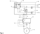
- Fig. 2 illustrates an exemplary electric connection diagram of a preferred embodiment of the present invention.
- a desired force F D is provided to the motion planning device 18 which is preferably arranged inside the electronic control device 10.
- the motion planning device 18 which may be a known device as it is used for articulated robots, is aware of the kinematics and the kinematic configuration of the articulated industrial robot 2. This means that the motion planning device 18 e.g. knows how the first arm 4 and the second arm 6 are coupled to each other and which are the movement constrains of the joint 1. This allows the motion planning device 18 to calculate the joint torques for a specific motion configuration, e.g. a posture, according to the kinematics or the inverse kinematics. In addition, the motion planning device 18 is able to calculate a joint torque for a specific force, or to retrieve a force for a specific or actual joint torque. This allows the motion planning device 18 to determine a set P of parameters which are needed to calculate the torque from a measured actual electric current and vice versa.
- a specific motion configuration e.g. a posture
- the motion planning device 18 is able to calculate a joint torque for a specific force, or to retrieve a force for a specific or actual joint
- the desired force F D is converted (calculated) into a desired torque T D by means of the motion planning device 18. To do so, the desired torque T D is calculated/ converted to a desired electric total current A and supplied to the electric drive unit 8.
- the electric drive unit 8 is calculating the three phase currents I U , I V , I W out of the electric total current A for each phase U, V, W of the three phase alternating current motor 14.
- the measuring device 12 is measuring the electric phase current of at least two phases I U , I V . Moreover, the measuring device 12 is determining and/or measuring the phase angle ⁇ and/or angular velocity ⁇ of at least one phase U, V, W and is providing the measured or determined quantity to said electronic control device 10 and preferable also to said motion planning device 18.
- the actual electric current I U , I V is checked against the total electric current A by an electric current comparator 20 according to the above-mentioned equation eq.1. If the equation is satisfied, an error signal E I is generated which indicates a plausible failure.
- the motion planning device 18 wants to move the robot 2 to a specific position or posture with a desired force F D , but a human next to the robot 2 is pushing against the second arm 6 of the robot 2. This leads to a deviation in motor currents, so that the total desired current A is not equal to the measured and calculated sum of currents I U , I V an I w . It shall be remarked that this example does not necessarily always lead to an appropriate deviation in torque, so that a comparison of the measured and calculated currents I U , I V alone may not be sufficient to detect a collision with a human in reliable manner.
- the measured actual currents I U , I V are converted (computed) into an actual torque T A and preferably provided to said motion planning device 18 and/or the torque comparator 22.
- the torque comparator 22 checks the actual torque T A against the desired torque T D . If an appropriate deviation is detected, an error signal E T is generated and the robot stopped or put into a safe operating mode.
- the motion planning device 18 is determining an actual force value F A from the actual torque value T A . Moreover, it provides the desired Force F D and the actual force F A to a force comparator 24. If an appropriate deviation in force is detected, an error signal E F is generated.
- the error signals E I , E T , E F are preferable provided to an external interface (not shown) of the electronic control device 10 for further processing, e.g. stop other nearby industrial robots.
- Fig. 3 illustrates an exemplary torque comparator 24.
- the desired torque T D and the actual torque T A are provided to said torque comparator 24 with all values being time-dependent.
- the actual torque value T A is compared to the desired torque value T D plus/minus a tolerance value.
- the upper boundary is indicated as T max and the lower boundary is indicated as T min . If T A is above T max or below T min , as indicated by the flash, an error signal E T is generated.
- the industrial articulated robot 2 is preferably stopped or put into a safe operating mode.
Landscapes
- Engineering & Computer Science (AREA)
- Robotics (AREA)
- Mechanical Engineering (AREA)
- Human Computer Interaction (AREA)
- Power Engineering (AREA)
- Manipulator (AREA)
Priority Applications (5)
| Application Number | Priority Date | Filing Date | Title |
|---|---|---|---|
| EP17176600.9A EP3418007A1 (fr) | 2017-06-19 | 2017-06-19 | Procédé de détermination d'un couple d'articulation dans l'articulation d'un robot industriel articulé |
| EP18702706.5A EP3641991B1 (fr) | 2017-06-19 | 2018-02-06 | Procédé de détermination d'un couple d'articulation dans l'articulation d'un robot industriel articulé |
| PCT/EP2018/052877 WO2018233880A1 (fr) | 2017-06-19 | 2018-02-06 | Procédé de détermination d'un couple d'articulation dans une articulation d'un robot industriel articulé |
| CN201880041153.7A CN110740840B (zh) | 2017-06-19 | 2018-02-06 | 确定铰接式工业机器人的关节中的关节转矩的方法 |
| US16/720,019 US10821610B2 (en) | 2017-06-19 | 2019-12-19 | Method of determining a joint torque in a joint of an articulated industrial robot |
Applications Claiming Priority (1)
| Application Number | Priority Date | Filing Date | Title |
|---|---|---|---|
| EP17176600.9A EP3418007A1 (fr) | 2017-06-19 | 2017-06-19 | Procédé de détermination d'un couple d'articulation dans l'articulation d'un robot industriel articulé |
Publications (1)
| Publication Number | Publication Date |
|---|---|
| EP3418007A1 true EP3418007A1 (fr) | 2018-12-26 |
Family
ID=59091376
Family Applications (2)
| Application Number | Title | Priority Date | Filing Date |
|---|---|---|---|
| EP17176600.9A Withdrawn EP3418007A1 (fr) | 2017-06-19 | 2017-06-19 | Procédé de détermination d'un couple d'articulation dans l'articulation d'un robot industriel articulé |
| EP18702706.5A Active EP3641991B1 (fr) | 2017-06-19 | 2018-02-06 | Procédé de détermination d'un couple d'articulation dans l'articulation d'un robot industriel articulé |
Family Applications After (1)
| Application Number | Title | Priority Date | Filing Date |
|---|---|---|---|
| EP18702706.5A Active EP3641991B1 (fr) | 2017-06-19 | 2018-02-06 | Procédé de détermination d'un couple d'articulation dans l'articulation d'un robot industriel articulé |
Country Status (4)
| Country | Link |
|---|---|
| US (1) | US10821610B2 (fr) |
| EP (2) | EP3418007A1 (fr) |
| CN (1) | CN110740840B (fr) |
| WO (1) | WO2018233880A1 (fr) |
Cited By (1)
| Publication number | Priority date | Publication date | Assignee | Title |
|---|---|---|---|---|
| CN110861096A (zh) * | 2019-12-21 | 2020-03-06 | 江苏开璇智能科技有限公司 | 一种机器人关节交互力感知与控制方法及装置 |
Families Citing this family (5)
| Publication number | Priority date | Publication date | Assignee | Title |
|---|---|---|---|---|
| JP6841802B2 (ja) * | 2018-08-31 | 2021-03-10 | ファナック株式会社 | ロボットおよびロボットシステム |
| US11385610B2 (en) * | 2019-08-16 | 2022-07-12 | Exato IP LLC | Stage automation system |
| CN114074325B (zh) * | 2020-08-14 | 2024-05-24 | 苏州艾利特机器人有限公司 | 一种确保机器人力边界限制的安全系统 |
| JP7447314B2 (ja) * | 2020-12-07 | 2024-03-11 | 株式会社ソニー・インタラクティブエンタテインメント | 情報処理装置、情報処理方法およびプログラム |
| US20220297293A1 (en) * | 2021-03-22 | 2022-09-22 | X Development Llc | Dynamic torque saturation limits for robot actuator(s) |
Citations (3)
| Publication number | Priority date | Publication date | Assignee | Title |
|---|---|---|---|---|
| EP1696216A1 (fr) * | 2005-02-25 | 2006-08-30 | Abb Ab | Procédé et dispositif pour mesurer le couple dans un robot |
| US20130211739A1 (en) * | 2012-02-14 | 2013-08-15 | Kuka Roboter Gmbh | Method For Determining A Torque And An Industrial Robot |
| WO2016110320A1 (fr) * | 2015-01-07 | 2016-07-14 | Abb Technology Ag | Procédé pour l'estimation de forces externes et de couples sur un bras de robot |
Family Cites Families (19)
| Publication number | Priority date | Publication date | Assignee | Title |
|---|---|---|---|---|
| US4864204A (en) * | 1986-11-20 | 1989-09-05 | Westinghouse Electric Corp. | Multiprocessor torque servo control for multiaxis digital robot control system |
| US4925312A (en) * | 1988-03-21 | 1990-05-15 | Staubli International Ag | Robot control system having adaptive feedforward torque control for improved accuracy |
| US6646405B2 (en) * | 2000-03-10 | 2003-11-11 | Iowa State University Research Foundation, Inc. | System and method for using joint torque feedback to prevent oscillation in a flexible robotic manipulator |
| JP4294646B2 (ja) * | 2003-07-29 | 2009-07-15 | パナソニック株式会社 | ロボットアームの制御方法および制御装置 |
| KR101474765B1 (ko) * | 2008-12-05 | 2014-12-22 | 삼성전자 주식회사 | 로봇 팔 및 그 제어방법 |
| US9119655B2 (en) * | 2012-08-03 | 2015-09-01 | Stryker Corporation | Surgical manipulator capable of controlling a surgical instrument in multiple modes |
| CN102055401B (zh) * | 2011-01-10 | 2012-06-27 | 武汉市菱电汽车电子有限责任公司 | 三相感应电动机单调节回路间接转矩控制系统及其方法 |
| DE102011003946A1 (de) * | 2011-02-10 | 2012-08-16 | Robert Bosch Gmbh | Verfahren zum Regeln eines von einer elektrischen Maschine in einem Kraftfahrzeug abgegebenen Ist-Drehmoments auf ein Soll-Drehmoment |
| KR102668586B1 (ko) * | 2012-08-03 | 2024-05-28 | 스트리커 코포레이션 | 로봇 수술을 위한 시스템 및 방법 |
| US9226796B2 (en) * | 2012-08-03 | 2016-01-05 | Stryker Corporation | Method for detecting a disturbance as an energy applicator of a surgical instrument traverses a cutting path |
| CN206123638U (zh) * | 2013-03-15 | 2017-04-26 | Sri国际公司 | 人体增强系统 |
| US9205556B1 (en) * | 2013-06-24 | 2015-12-08 | Redwood Robotics, Inc. | Cogging torque measurement for a robot actuator |
| US9745081B2 (en) * | 2013-07-12 | 2017-08-29 | The Boeing Company | Apparatus and method for moving a structure in a manufacturing environment |
| JP5905443B2 (ja) * | 2013-12-25 | 2016-04-20 | ファナック株式会社 | 人協調型産業用ロボットの外力判定方法および外力判定装置 |
| CN103701393B (zh) * | 2013-12-27 | 2016-04-13 | 深圳市航盛电子股份有限公司 | 一种异步电机弱磁时转矩精度的补偿方法 |
| JP6632204B2 (ja) * | 2015-03-13 | 2020-01-22 | キヤノン株式会社 | 駆動装置、ロボット装置、および物品の製造方法 |
| JP6659730B2 (ja) * | 2015-05-21 | 2020-03-04 | カスタニエンバウム ジーエムビーエイチ | アクチュエータ駆動ロボットジョイントの開ループ/閉ループ制御のための方法および装置 |
| US9862099B1 (en) * | 2015-06-22 | 2018-01-09 | X Development Llc | Haptic controller with touch-sensitive control knob |
| WO2017024409A1 (fr) * | 2015-08-11 | 2017-02-16 | Genesis Robotics Llp | Machine électrique |
-
2017
- 2017-06-19 EP EP17176600.9A patent/EP3418007A1/fr not_active Withdrawn
-
2018
- 2018-02-06 EP EP18702706.5A patent/EP3641991B1/fr active Active
- 2018-02-06 WO PCT/EP2018/052877 patent/WO2018233880A1/fr not_active Ceased
- 2018-02-06 CN CN201880041153.7A patent/CN110740840B/zh active Active
-
2019
- 2019-12-19 US US16/720,019 patent/US10821610B2/en active Active
Patent Citations (3)
| Publication number | Priority date | Publication date | Assignee | Title |
|---|---|---|---|---|
| EP1696216A1 (fr) * | 2005-02-25 | 2006-08-30 | Abb Ab | Procédé et dispositif pour mesurer le couple dans un robot |
| US20130211739A1 (en) * | 2012-02-14 | 2013-08-15 | Kuka Roboter Gmbh | Method For Determining A Torque And An Industrial Robot |
| WO2016110320A1 (fr) * | 2015-01-07 | 2016-07-14 | Abb Technology Ag | Procédé pour l'estimation de forces externes et de couples sur un bras de robot |
Non-Patent Citations (1)
| Title |
|---|
| "ISO 10218-1:2011, Robots and robotic devices - Safety requirements for industrial robots", 2011, ISO |
Cited By (1)
| Publication number | Priority date | Publication date | Assignee | Title |
|---|---|---|---|---|
| CN110861096A (zh) * | 2019-12-21 | 2020-03-06 | 江苏开璇智能科技有限公司 | 一种机器人关节交互力感知与控制方法及装置 |
Also Published As
| Publication number | Publication date |
|---|---|
| EP3641991A1 (fr) | 2020-04-29 |
| US20200122337A1 (en) | 2020-04-23 |
| US10821610B2 (en) | 2020-11-03 |
| WO2018233880A1 (fr) | 2018-12-27 |
| CN110740840A (zh) | 2020-01-31 |
| EP3641991B1 (fr) | 2022-11-30 |
| CN110740840B (zh) | 2023-03-10 |
Similar Documents
| Publication | Publication Date | Title |
|---|---|---|
| EP3641991B1 (fr) | Procédé de détermination d'un couple d'articulation dans l'articulation d'un robot industriel articulé | |
| US9737989B2 (en) | Human cooperation robot system in which robot is caused to perform retreat operation | |
| US9827681B2 (en) | Human cooperation robot system in which robot is caused to perform retreat operation depending on external force | |
| US11548153B2 (en) | Robot comprising safety system ensuring stopping time and distance | |
| EP3369536B1 (fr) | Dispositif de surveillance pour système robotisé | |
| US10399232B2 (en) | Safety system for industrial robot | |
| US8594847B2 (en) | Manipulator, particularly industrial robot, having a redundant sensor arrangement, and method for the control thereof | |
| Rosenstrauch et al. | Human robot collaboration-using kinect v2 for iso/ts 15066 speed and separation monitoring | |
| JP6145153B2 (ja) | ロボットの非常停止の発生状況を記録するロボット制御装置 | |
| US20180361578A1 (en) | Monitoring device of robot system | |
| US11389959B2 (en) | Robot system | |
| CN110174873B (zh) | 伺服控制装置 | |
| US20140366673A1 (en) | Robot | |
| US10699929B2 (en) | Controller of transfer device | |
| US11358276B2 (en) | Robot and robot system | |
| CN110831730B (zh) | 机器人系统 | |
| CN114851186B (zh) | 机器人控制装置及机器人系统 | |
| Je et al. | A study of the collision detection of robot manipulator without torque sensor | |
| US11784606B2 (en) | Method and device for a failsafe rotational speed monitoring process | |
| JP4577607B2 (ja) | ロボットの制御装置およびロボットシステム | |
| JP2002144277A (ja) | ロボット | |
| Kartashev et al. | Automatic safe motion control system for a robotic manipulator | |
| JP2006116635A5 (fr) | ||
| US12318920B2 (en) | Safety system, joint assembly with safety system, and robot having joint assembly | |
| JPS5877488A (ja) | 工業用ロボツトの暴走防止装置 |
Legal Events
| Date | Code | Title | Description |
|---|---|---|---|
| PUAI | Public reference made under article 153(3) epc to a published international application that has entered the european phase |
Free format text: ORIGINAL CODE: 0009012 |
|
| AK | Designated contracting states |
Kind code of ref document: A1 Designated state(s): AL AT BE BG CH CY CZ DE DK EE ES FI FR GB GR HR HU IE IS IT LI LT LU LV MC MK MT NL NO PL PT RO RS SE SI SK SM TR |
|
| AX | Request for extension of the european patent |
Extension state: BA ME |
|
| STAA | Information on the status of an ep patent application or granted ep patent |
Free format text: STATUS: THE APPLICATION HAS BEEN WITHDRAWN |
|
| 18W | Application withdrawn |
Effective date: 20190625 |