EP3418145B1 - Fahrzeugverhaltensteuerungsvorrichtung - Google Patents
Fahrzeugverhaltensteuerungsvorrichtung Download PDFInfo
- Publication number
- EP3418145B1 EP3418145B1 EP17785757.0A EP17785757A EP3418145B1 EP 3418145 B1 EP3418145 B1 EP 3418145B1 EP 17785757 A EP17785757 A EP 17785757A EP 3418145 B1 EP3418145 B1 EP 3418145B1
- Authority
- EP
- European Patent Office
- Prior art keywords
- vehicle
- deceleration
- control device
- driving force
- steering speed
- Prior art date
- Legal status (The legal status is an assumption and is not a legal conclusion. Google has not performed a legal analysis and makes no representation as to the accuracy of the status listed.)
- Active
Links
Images



Classifications
-
- B—PERFORMING OPERATIONS; TRANSPORTING
- B60—VEHICLES IN GENERAL
- B60W—CONJOINT CONTROL OF VEHICLE SUB-UNITS OF DIFFERENT TYPE OR DIFFERENT FUNCTION; CONTROL SYSTEMS SPECIALLY ADAPTED FOR HYBRID VEHICLES; ROAD VEHICLE DRIVE CONTROL SYSTEMS FOR PURPOSES NOT RELATED TO THE CONTROL OF A PARTICULAR SUB-UNIT
- B60W30/00—Purposes of road vehicle drive control systems not related to the control of a particular sub-unit, e.g. of systems using conjoint control of vehicle sub-units
- B60W30/02—Control of vehicle driving stability
-
- B—PERFORMING OPERATIONS; TRANSPORTING
- B60—VEHICLES IN GENERAL
- B60K—ARRANGEMENT OR MOUNTING OF PROPULSION UNITS OR OF TRANSMISSIONS IN VEHICLES; ARRANGEMENT OR MOUNTING OF PLURAL DIVERSE PRIME-MOVERS IN VEHICLES; AUXILIARY DRIVES FOR VEHICLES; INSTRUMENTATION OR DASHBOARDS FOR VEHICLES; ARRANGEMENTS IN CONNECTION WITH COOLING, AIR INTAKE, GAS EXHAUST OR FUEL SUPPLY OF PROPULSION UNITS IN VEHICLES
- B60K28/00—Safety devices for propulsion-unit control, specially adapted for, or arranged in, vehicles, e.g. preventing fuel supply or ignition in the event of potentially dangerous conditions
- B60K28/02—Safety devices for propulsion-unit control, specially adapted for, or arranged in, vehicles, e.g. preventing fuel supply or ignition in the event of potentially dangerous conditions responsive to conditions relating to the driver
-
- B—PERFORMING OPERATIONS; TRANSPORTING
- B60—VEHICLES IN GENERAL
- B60W—CONJOINT CONTROL OF VEHICLE SUB-UNITS OF DIFFERENT TYPE OR DIFFERENT FUNCTION; CONTROL SYSTEMS SPECIALLY ADAPTED FOR HYBRID VEHICLES; ROAD VEHICLE DRIVE CONTROL SYSTEMS FOR PURPOSES NOT RELATED TO THE CONTROL OF A PARTICULAR SUB-UNIT
- B60W10/00—Conjoint control of vehicle sub-units of different type or different function
- B60W10/04—Conjoint control of vehicle sub-units of different type or different function including control of propulsion units
-
- B—PERFORMING OPERATIONS; TRANSPORTING
- B60—VEHICLES IN GENERAL
- B60W—CONJOINT CONTROL OF VEHICLE SUB-UNITS OF DIFFERENT TYPE OR DIFFERENT FUNCTION; CONTROL SYSTEMS SPECIALLY ADAPTED FOR HYBRID VEHICLES; ROAD VEHICLE DRIVE CONTROL SYSTEMS FOR PURPOSES NOT RELATED TO THE CONTROL OF A PARTICULAR SUB-UNIT
- B60W10/00—Conjoint control of vehicle sub-units of different type or different function
- B60W10/20—Conjoint control of vehicle sub-units of different type or different function including control of steering systems
-
- B—PERFORMING OPERATIONS; TRANSPORTING
- B60—VEHICLES IN GENERAL
- B60W—CONJOINT CONTROL OF VEHICLE SUB-UNITS OF DIFFERENT TYPE OR DIFFERENT FUNCTION; CONTROL SYSTEMS SPECIALLY ADAPTED FOR HYBRID VEHICLES; ROAD VEHICLE DRIVE CONTROL SYSTEMS FOR PURPOSES NOT RELATED TO THE CONTROL OF A PARTICULAR SUB-UNIT
- B60W30/00—Purposes of road vehicle drive control systems not related to the control of a particular sub-unit, e.g. of systems using conjoint control of vehicle sub-units
- B60W30/02—Control of vehicle driving stability
- B60W30/025—Control of vehicle driving stability related to comfort of drivers or passengers
-
- B—PERFORMING OPERATIONS; TRANSPORTING
- B60—VEHICLES IN GENERAL
- B60W—CONJOINT CONTROL OF VEHICLE SUB-UNITS OF DIFFERENT TYPE OR DIFFERENT FUNCTION; CONTROL SYSTEMS SPECIALLY ADAPTED FOR HYBRID VEHICLES; ROAD VEHICLE DRIVE CONTROL SYSTEMS FOR PURPOSES NOT RELATED TO THE CONTROL OF A PARTICULAR SUB-UNIT
- B60W30/00—Purposes of road vehicle drive control systems not related to the control of a particular sub-unit, e.g. of systems using conjoint control of vehicle sub-units
- B60W30/02—Control of vehicle driving stability
- B60W30/045—Improving turning performance
-
- B—PERFORMING OPERATIONS; TRANSPORTING
- B60—VEHICLES IN GENERAL
- B60W—CONJOINT CONTROL OF VEHICLE SUB-UNITS OF DIFFERENT TYPE OR DIFFERENT FUNCTION; CONTROL SYSTEMS SPECIALLY ADAPTED FOR HYBRID VEHICLES; ROAD VEHICLE DRIVE CONTROL SYSTEMS FOR PURPOSES NOT RELATED TO THE CONTROL OF A PARTICULAR SUB-UNIT
- B60W50/00—Details of control systems for road vehicle drive control not related to the control of a particular sub-unit, e.g. process diagnostic or vehicle driver interfaces
- B60W50/0098—Details of control systems ensuring comfort, safety or stability not otherwise provided for
-
- B—PERFORMING OPERATIONS; TRANSPORTING
- B62—LAND VEHICLES FOR TRAVELLING OTHERWISE THAN ON RAILS
- B62D—MOTOR VEHICLES; TRAILERS
- B62D6/00—Arrangements for automatically controlling steering depending on driving conditions sensed and responded to, e.g. control circuits
-
- B—PERFORMING OPERATIONS; TRANSPORTING
- B60—VEHICLES IN GENERAL
- B60W—CONJOINT CONTROL OF VEHICLE SUB-UNITS OF DIFFERENT TYPE OR DIFFERENT FUNCTION; CONTROL SYSTEMS SPECIALLY ADAPTED FOR HYBRID VEHICLES; ROAD VEHICLE DRIVE CONTROL SYSTEMS FOR PURPOSES NOT RELATED TO THE CONTROL OF A PARTICULAR SUB-UNIT
- B60W2510/00—Input parameters relating to a particular sub-units
- B60W2510/20—Steering systems
- B60W2510/205—Steering speed
-
- B—PERFORMING OPERATIONS; TRANSPORTING
- B60—VEHICLES IN GENERAL
- B60W—CONJOINT CONTROL OF VEHICLE SUB-UNITS OF DIFFERENT TYPE OR DIFFERENT FUNCTION; CONTROL SYSTEMS SPECIALLY ADAPTED FOR HYBRID VEHICLES; ROAD VEHICLE DRIVE CONTROL SYSTEMS FOR PURPOSES NOT RELATED TO THE CONTROL OF A PARTICULAR SUB-UNIT
- B60W2520/00—Input parameters relating to overall vehicle dynamics
- B60W2520/10—Longitudinal speed
-
- B—PERFORMING OPERATIONS; TRANSPORTING
- B60—VEHICLES IN GENERAL
- B60W—CONJOINT CONTROL OF VEHICLE SUB-UNITS OF DIFFERENT TYPE OR DIFFERENT FUNCTION; CONTROL SYSTEMS SPECIALLY ADAPTED FOR HYBRID VEHICLES; ROAD VEHICLE DRIVE CONTROL SYSTEMS FOR PURPOSES NOT RELATED TO THE CONTROL OF A PARTICULAR SUB-UNIT
- B60W2540/00—Input parameters relating to occupants
- B60W2540/10—Accelerator pedal position
-
- B—PERFORMING OPERATIONS; TRANSPORTING
- B60—VEHICLES IN GENERAL
- B60W—CONJOINT CONTROL OF VEHICLE SUB-UNITS OF DIFFERENT TYPE OR DIFFERENT FUNCTION; CONTROL SYSTEMS SPECIALLY ADAPTED FOR HYBRID VEHICLES; ROAD VEHICLE DRIVE CONTROL SYSTEMS FOR PURPOSES NOT RELATED TO THE CONTROL OF A PARTICULAR SUB-UNIT
- B60W2540/00—Input parameters relating to occupants
- B60W2540/18—Steering angle
-
- B—PERFORMING OPERATIONS; TRANSPORTING
- B60—VEHICLES IN GENERAL
- B60W—CONJOINT CONTROL OF VEHICLE SUB-UNITS OF DIFFERENT TYPE OR DIFFERENT FUNCTION; CONTROL SYSTEMS SPECIALLY ADAPTED FOR HYBRID VEHICLES; ROAD VEHICLE DRIVE CONTROL SYSTEMS FOR PURPOSES NOT RELATED TO THE CONTROL OF A PARTICULAR SUB-UNIT
- B60W2552/00—Input parameters relating to infrastructure
-
- B—PERFORMING OPERATIONS; TRANSPORTING
- B60—VEHICLES IN GENERAL
- B60W—CONJOINT CONTROL OF VEHICLE SUB-UNITS OF DIFFERENT TYPE OR DIFFERENT FUNCTION; CONTROL SYSTEMS SPECIALLY ADAPTED FOR HYBRID VEHICLES; ROAD VEHICLE DRIVE CONTROL SYSTEMS FOR PURPOSES NOT RELATED TO THE CONTROL OF A PARTICULAR SUB-UNIT
- B60W2710/00—Output or target parameters relating to a particular sub-units
-
- B—PERFORMING OPERATIONS; TRANSPORTING
- B60—VEHICLES IN GENERAL
- B60W—CONJOINT CONTROL OF VEHICLE SUB-UNITS OF DIFFERENT TYPE OR DIFFERENT FUNCTION; CONTROL SYSTEMS SPECIALLY ADAPTED FOR HYBRID VEHICLES; ROAD VEHICLE DRIVE CONTROL SYSTEMS FOR PURPOSES NOT RELATED TO THE CONTROL OF A PARTICULAR SUB-UNIT
- B60W2710/00—Output or target parameters relating to a particular sub-units
- B60W2710/06—Combustion engines, Gas turbines
- B60W2710/0666—Engine torque
-
- B—PERFORMING OPERATIONS; TRANSPORTING
- B60—VEHICLES IN GENERAL
- B60W—CONJOINT CONTROL OF VEHICLE SUB-UNITS OF DIFFERENT TYPE OR DIFFERENT FUNCTION; CONTROL SYSTEMS SPECIALLY ADAPTED FOR HYBRID VEHICLES; ROAD VEHICLE DRIVE CONTROL SYSTEMS FOR PURPOSES NOT RELATED TO THE CONTROL OF A PARTICULAR SUB-UNIT
- B60W2710/00—Output or target parameters relating to a particular sub-units
- B60W2710/20—Steering systems
-
- B—PERFORMING OPERATIONS; TRANSPORTING
- B60—VEHICLES IN GENERAL
- B60W—CONJOINT CONTROL OF VEHICLE SUB-UNITS OF DIFFERENT TYPE OR DIFFERENT FUNCTION; CONTROL SYSTEMS SPECIALLY ADAPTED FOR HYBRID VEHICLES; ROAD VEHICLE DRIVE CONTROL SYSTEMS FOR PURPOSES NOT RELATED TO THE CONTROL OF A PARTICULAR SUB-UNIT
- B60W2720/00—Output or target parameters relating to overall vehicle dynamics
- B60W2720/10—Longitudinal speed
- B60W2720/106—Longitudinal acceleration
Definitions
- the present invention relates to a vehicle behavior control device, and more particularly to a vehicle behavior control device for controlling behavior of a vehicle having steerable front road wheels.
- control system capable of, in a situation where behavior of a vehicle becomes unstable due to road wheel slip or the like, controlling the vehicle behavior to enable a safe traveling (e.g., an antiskid brake system).
- a control system operable to detect the occurrence of vehicle understeer or oversteer behavior during vehicle cornering or the like, and apply an appropriate degree of deceleration to one or more road wheels so as to suppress such a behavior.
- JP 2005 145143 A shows a vehicle behavior control device where, in order to perform more appropriate deceleration control in a scene where a driver performs a sudden steering operation, a target deceleration Xg* is calculated according to the deviation between the turning radius R and the deceleration start threshold Rs, and the deviation between the turning speed V and the deceleration start threshold Vs.
- the steering angular velocity ⁇ is equal to or more than the predetermined value ⁇ 1
- the target deceleration Xg* is corrected by the correction coefficient K1 which is set to increase as the steering angular velocity ⁇ increases so that a more appropriate deceleration control can be performed.
- an automatic deceleration is performed by increasing the hydraulic pressure of each wheel cylinder and suppressing an engine output.
- a target brake fluid pressure Pi* for each wheel cylinder required to achieve the target deceleration Xg* is calculated, and the braking force control device is controlled so that the brake fluid pressure of each wheel cylinder is set to the target brake fluid pressure Pi*.
- a further vehicle behavior control device is known from JP 2008 110620 A .
- Patent Literature 1 focuses on that a driver performing only a steering operation for turning is allowed to realize a vehicle motion similar to the vehicle motion of an expert driver.
- the conventional technique does not necessarily acquire improvement in responsivity of vehicle behavior and a linear feeling with respect to a standard steering wheel operation.
- the present invention has been made to solve the above conventional problem, and an object thereof is to provide a vehicle behavior control device capable of improving responsivity of vehicle behavior and a linear feeling with respect to a steering wheel operation without causing a driver to experience a strong feeling of intervention of the control and, at the same time, capable of controlling behavior of a vehicle in such a manner as to also improve stability of the vehicle attitude and riding comfort.
- a vehicle behavior control device of the present invention is directed to a vehicle behavior control device applied to a vehicle having a steerable front road wheel, the vehicle behavior control device including: a steering speed acquiring part configured to acquire a steering speed of the vehicle; a driving force reduction flag setting part configured to set a driving force reduction flag, indicative of whether or not a condition for allowing a reduction of a driving force of the vehicle is satisfied, based on the steering speed; and a driving force reducing part configured to acquire a target additional deceleration to be added to the vehicle based on the steering speed, decide a driving force reduction amount required for realizing the target additional deceleration and start to reduce the driving force of the vehicle when the driving force reduction flag is set to a true value indicative of a state in which the condition for allowing the reduction of the driving force of the vehicle is satisfied, the vehicle behavior control device being characterized in that the target additional deceleration increases to be closer to an upper limit value 0.5 m/s 2 as the steering speed increases.
- the driving force reducing part starts to reduce the driving force of the vehicle based on the steering speed when the driving force reduction flag is set to the true value indicative of a state in which the condition for allowing the reduction of the driving force of the vehicle is satisfied. Accordingly, immediately after a start of a steering wheel operation performed by a driver, the driving force is reduced so as to increase a vertical load on the front road wheel and hence, it is possible to control behavior of the vehicle with good responsivity with respect to a steering wheel operation performed by a driver. Therefore, it is possible to improve responsivity of vehicle behavior and a linear feeling with respect to the steering wheel operation without causing the driver to experience a strong feeling of intervention of the control. Further, behavior which is intended by the driver is accurately realized and hence, extremely small correction steering becomes unnecessary thus also improving stability of the vehicle attitude and riding comfort.
- the driving force reduction flag setting part is configured to set the driving force reduction flag to the true value when the steering speed exceeds a given threshold.
- the present invention having such a configuration, when the steering speed is equal to or lower than the threshold, it is possible to suppress the excessive reaction of the vehicle with respect to an extremely small steering wheel operation. Therefore, it is possible to control behavior of the vehicle in such a manner as to accurately realize behavior which is intended by the driver without causing the driver to feel discomfort with respect to vehicle behavior during straight traveling.
- the driving force reducing part is configured to decide an additional deceleration based on the target additional deceleration, under a condition that a change rate of the additional deceleration is equal to or less than 0.5 m/s 3 , and decide a driving force reduction amount required for realizing the decided additional deceleration.
- the vehicle behavior control device it is possible to improve responsivity of vehicle behavior and a linear feeling with respect to a steering wheel operation without causing a driver to experience a strong feeling of intervention of the control and, at the same time, to control behavior of a vehicle in such a manner as to also improve stability of the vehicle attitude and riding comfort.
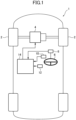
- FIG. 1 is a block diagram depicting an entire configuration of the vehicle equipped with the vehicle behavior control device according to the embodiment of the present invention.
- the reference sign 1 denotes the vehicle equipped with the vehicle behavior control device according to this embodiment.
- a vehicle body of the vehicle 1 has a front portion on which an engine 4 for driving drive road wheels (in the example depicted in FIG. 1 , right and left front road wheels 2) is mounted.
- the engine 4 is an internal combustion engine such as a gasoline engine or a diesel engine.
- the vehicle 1 has: a steering wheel angle sensor 8 for detecting a rotational angle of a steering wheel 6; an accelerator position sensor 10 for detecting an amount of depression of an accelerator pedal (accelerator position); and a vehicle speed sensor 12 for detecting a vehicle speed.
- a steering wheel angle sensor 8 for detecting a rotational angle of a steering wheel 6
- an accelerator position sensor 10 for detecting an amount of depression of an accelerator pedal (accelerator position)
- a vehicle speed sensor 12 for detecting a vehicle speed.
- Each of the above sensors is operable to output a detection value to a PCM (Power-train Control Module) 14.
- PCM Power-train Control Module
- FIG. 2 is a block diagram depicting the electrical configuration of the vehicle behavior control device according to the embodiment of the present invention.
- the PCM 14 is configured to, based on detection signals output from various sensors for detecting an operating state of the engine 4 besides detection signals output from the above sensors 8 to 12, output control signals to perform controls with respect to respective constitutional elements (e.g., a throttle valve, a turbocharger, a variable valve mechanism, an ignition unit, a fuel injection valve, and an EGR unit) of the engine 4.
- respective constitutional elements e.g., a throttle valve, a turbocharger, a variable valve mechanism, an ignition unit, a fuel injection valve, and an EGR unit
- the PCM 14 includes: a basic target torque-deciding part 16 for deciding a basic target torque based on a driving state of the vehicle 1 including an accelerator pedal operation; a torque reduction amount-deciding part 18 for deciding a torque reduction amount for adding a deceleration to the vehicle 1 based on a steering speed of the vehicle 1; a final target torque-deciding part 20 for deciding a final target torque based on the basic target torque and the torque reduction amount; and an engine control part 22 for controlling the engine 4 to cause the engine 4 to output the final target torque.
- Respective components of the PCM 14 are functionally realized by a computer which includes: a CPU; various programs (including a basic control program such as an OS, and an application program capable of being activated on the OS to realize a specific function) to be interpreted and executed on the CPU; and an internal memory such as a ROM or a RAM for storing the programs and various data.
- a computer which includes: a CPU; various programs (including a basic control program such as an OS, and an application program capable of being activated on the OS to realize a specific function) to be interpreted and executed on the CPU; and an internal memory such as a ROM or a RAM for storing the programs and various data.
- the PCM 14 is equivalent to "vehicle behavior control device" according to the present invention, and functions as a “steering speed acquiring part", a “driving force reduction flag setting part”, and a “driving force reducing part", although details thereof will be described later.
- FIG. 3 is a flowchart of engine control processing to be performed by the vehicle behavior control device according to the embodiment of the present invention, so as to control the engine 4.
- FIG. 4 is a flowchart of torque reduction amount-deciding processing to be performed by the vehicle behavior control device according to the embodiment of the present invention, so as to decide the torque reduction amount.
- FIG. 5 is a map depicting a relationship between the steering speed, and a target additional deceleration to be decided by the vehicle behavior control device according to the embodiment of the present invention.
- the engine control processing in FIG. 3 is activated when an ignition switch of the vehicle 1 is turned on to apply power to the vehicle behavior control device, and repeatedly executed.
- the PCM 14 upon start of the engine control processing, in step S1, the PCM 14 operates to acquire various information about the driving state of the vehicle 1. Specifically, the PCM 14 operates to acquire, as information about the driving state, detection signals output from the aforementioned various sensors, including the steering wheel angle detected by the steering wheel angle sensor 8, the accelerator position detected by the accelerator position sensor 10, the vehicle speed detected by the vehicle speed sensor 12, and a gear stage currently set in a transmission of the vehicle 1.
- the basic target torque-deciding part 16 of the PCM 14 operates to set a target acceleration based on the driving state of the vehicle 1 including the accelerator pedal operation, acquired in step S1.
- the basic target torque-deciding part 16 operates to select, from acceleration characteristic maps in which various vehicle speeds and various gear stages are defined (the maps are preliminarily created and stored in a memory or the like), an acceleration characteristic map which corresponds to a current vehicle speed and a current gear stage, and decide a target acceleration corresponding to a current accelerator position, with reference to the selected acceleration characteristic map.
- step S3 the basic target torque-deciding part 16 operates to decide the basic target torque of the engine 4 for realizing the target acceleration decided in step S2.
- the basic target torque-deciding part 16 operates to decide the basic target torque within a torque range outputtable by the engine 4, based on current vehicle speed, gear stage, road grade, road surface ⁇ , etc.
- step S4 the torque reduction amount-deciding part 18 operates to perform the torque reduction amount-deciding processing of deciding the torque reduction amount for adding a deceleration to the vehicle 1, based on a steering wheel operation. This torque reduction amount-deciding processing will be described with reference to FIG. 4 .
- step S21 the torque reduction amount-deciding part 18 operates to calculate the steering speed based on the steering wheel angle acquired in step S1.
- step S22 the torque reduction amount-deciding part 18 operates to determine whether or not the steering speed is greater than a given threshold Tsi.
- step S23 the torque reduction amount-deciding part 18 operates to set the torque reduction flag, indicative of whether or not a condition for allowing reduction of an output torque of the engine 4 so as to add a deceleration to the vehicle 1 is satisfied, to True (true value) indicative of a state in which the condition for allowing the torque reduction is satisfied.
- step S24 the torque reduction amount-deciding part 18 operates to acquire the target additional deceleration based on the steering speed.
- This target additional deceleration is a deceleration to be added to the vehicle 1 according to the steering wheel operation in order to accurately realize vehicle behavior which is intended by a driver.
- the torque reduction amount-deciding part 18 operates to acquire a target additional deceleration which corresponds to the steering speed calculated in step S21, based on a relationship between the target additional deceleration and the steering speed, represented by the map in FIG. 5 .
- the horizontal axis represents the steering speed
- the vertical axis represents the target additional deceleration.
- a corresponding target additional deceleration is 0. That is, when the steering speed is equal to or less than the threshold T S1 , the PCM 14 operates to stop control of adding a deceleration to the vehicle 1 (specifically, reduction of an output torque of the engine 4) based on the steering wheel operation.
- a target additional deceleration which corresponds to the steering speed comes closer to a given upper limit value D max . That is, as the steering speed is increased to a higher value, the target additional deceleration is increased, and a rate of increase of the target additional deceleration becomes smaller.
- This upper limit value D max is set to a deceleration (e.g., 0.5 m/s 2 ⁇ 0.05 G) to the extent that a driver does not feel intervention of the control even when the deceleration is added to the vehicle 1 according to the steering wheel operation.
- the target additional deceleration is maintained at the upper limit value D max .
- step S25 the torque reduction amount-deciding part 18 operates to decide an additional deceleration in the current processing, under a condition that a change rate of the additional deceleration is equal to or less than a threshold Rmax (e.g., 0.5 m/s 3 ).
- a threshold Rmax e.g., 0.5 m/s 3
- the torque reduction amount-deciding part 18 operates to, when a change rate from the additional deceleration decided in the last processing to the target additional deceleration acquired in step S24 in the current processing is equal to or less than the threshold Rmax, decide the target additional deceleration acquired in step S24, as the additional deceleration in the current processing.
- the torque reduction amount-deciding part 18 operates to, when the change rate from the additional deceleration decided in the last processing to the target additional deceleration acquired in step S24 in the current processing is greater than the threshold Rmax, decide, as the additional deceleration in the current processing, a value obtained by changing the additional deceleration decided in the last processing until the current processing at the change rate Rmax.
- step S26 the torque reduction amount-deciding part 18 operates to decide the torque reduction amount, based on the current additional deceleration decided in step S25. Specifically, the torque reduction amount-deciding part 18 operates to decide a torque reduction amount required for realizing the current additional deceleration, based on the current vehicle speed, gear stage, road gradient and others acquired in step S1.
- step S22 when the steering speed is not greater than the threshold T S1 , (i.e., when the steering speed is equal to or lower than the threshold T S1 ), the processing advances to step S27.
- step S27 the torque reduction amount-deciding part 18 operates to set the torque reduction flag, indicative of whether or not the condition for allowing reduction of the output torque of the engine 4 so as to add a deceleration to the vehicle 1 is satisfied, to False (false value) indicative of a state in which the condition for allowing the torque reduction is not satisfied.
- step S26 or S27 the torque reduction amount-deciding part 18 operates to finish the torque reduction amount-deciding processing, and the processing returns to the main routine.
- step S5 the final target torque-deciding part 20 operates to subtract the torque reduction amount decided in the torque reduction amount-deciding processing in step S4, from the basic target torque decided in step S3, to thereby decide the final target torque.
- step S6 the engine control part 22 operates to control the engine 4 to cause the engine 4 to output the final target torque set in step S5.
- the engine control part 22 operates to, based on the final target torque set in step S5 and an engine speed, decide various state amounts (e.g., air charge amount, fuel injection amount, intake-air temperature, and oxygen concentration) required for realizing the final target torque, and then, based on the decided state amounts, control respective actuators for driving the respective constitutional elements of the engine 4.
- the engine control part 22 operates to set a limit value or a limit range corresponding to the state amount, and set a controlled variable of each actuator to enable its related state amount to preserve limitation by the limit value or the limit range, so as to execute control.
- step S6 the PCM 14 operates to finish the engine control processing.
- FIG. 6 is a time chart depicting a temporal change of parameters pertaining to the engine control during turning of the vehicle 1 equipped with the vehicle behavior control device according to the embodiment of the present invention.
- the chart (a) of FIG. 6 is a plan view schematically depicting the vehicle 1 which is turning in a clockwise direction. As depicted in the chart (a) of FIG. 6 , the vehicle 1 starts turning in the clockwise direction from a position A, and continues turning in the clockwise direction at a constant steering wheel angle from a position B to a position C.
- the chart (b) of FIG. 6 is a diagram depicting a change in steering wheel angle of the vehicle 1 which is turning in the clockwise direction as depicted in the chart (a) of FIG. 6 .
- the horizontal axis represents the time
- the vertical axis represents the steering wheel angle.
- clockwise steering is started at the position A, and then, along with an additional turning operation of the steering wheel, a clockwise steering wheel angle gradually increases, and the clockwise steering wheel angle reaches maximum at the position B. Thereafter, the steering wheel angle is maintained constant until the position C (maintaining of steering wheel).
- the chart (c) of FIG. 6 is a diagram depicting a change in steering speed of the vehicle 1 which is turning in the clockwise direction as depicted in the chart (a) of FIG. 6 .
- the horizontal axis represents the time
- the vertical axis represents the steering speed.
- the steering speed of the vehicle 1 is expressed as a temporal differentiation of the steering wheel angle of the vehicle 1. That is, as depicted in the chart (c) of FIG. 6 , when clockwise steering is started at the position A, a clockwise steering speed arises, and the steering speed is maintained approximately constant in an intermediate zone between the position A and the position B. Thereafter, the clockwise steering speed decreases and, when the clockwise steering wheel angle reaches maximum at the position B, the steering speed becomes 0. Further, in an intermediate zone between the position B and the position C where the clockwise steering wheel angle is maintained, the steering speed remains at 0.
- the chart (d) of FIG. 6 is a diagram depicting a truth value of the torque reduction flag set based on the steering speed.
- the horizontal axis represents the time
- the vertical axis represents the truth value of the torque reduction flag.
- the torque reduction flag is set to False.
- the torque reduction flag is changed from False to True when the steering speed exceeds the threshold T S1 .
- the steering speed decreases as the vehicle 1 approaches the position B and, when the steering speed becomes equal to or lower than the threshold T S1 , the torque reduction flag is changed from True to False.
- the chart (e) of FIG. 6 is a diagram depicting a change in additional deceleration decided based on the steering speed and the torque reduction flag.
- the horizontal axis represents the time
- the vertical axis represents the additional deceleration.
- the torque reduction amount-deciding part 18 operates, when the steering speed is greater than the threshold T S1 (that is, when the torque reduction flag is True) in step S22, to acquire the target additional deceleration based on the steering speed in step S24. Subsequently, in step S25, the torque reduction amount-deciding part 18 operates to decide the additional deceleration in each processing cycle, under a condition that the increase rate of the additional deceleration is equal to or less than the threshold Rmax.
- the additional deceleration starts increasing from a point at which the torque reduction flag is switched from False to True, and is maintained approximately constant in an intermediate zone between the position A and the position B. Thereafter, the additional deceleration decreases in accordance with a decrease in steering speed, and becomes 0 when the torque reduction flag is switched from True to False.
- the chart (f) of FIG. 6 is a diagram depicting a change in torque reduction amount decided based on the additional deceleration depicted in the chart (e) of FIG. 6 .
- the horizontal axis represents the time
- the vertical axis represents the torque reduction amount.
- the torque reduction amount-deciding part 18 operates to decide the torque reduction amount required for realizing an additional deceleration, based on parameters such as the current vehicle speed, gear stage and road grade.
- the torque reduction amount is decided so as to change in the same pattern as that of the additional deceleration depicted in the chart (e) of FIG. 6 .
- the chart (g) of FIG. 6 is a diagram depicting a change in final target torque decided based on the basic target torque and the torque reduction amount.
- the horizontal axis represents the time
- the vertical axis represents the torque.
- the broken line indicates the basic target torque
- the solid line indicates the final target torque.
- the final target torque-deciding part 20 operates to subtract the torque reduction amount decided in the torque reduction amount-deciding processing in step S4, from the basic target torque decided in step S3, to thereby decide the final target torque.
- the final target torque is reduced from the basic target torque by an amount corresponding to the torque reduction amount, and deceleration which corresponds to this torque reduction is generated in the vehicle 1 and hence, a load shift to the front road wheels 2 occurs.
- a frictional force between the front road wheels 2 and a road surface increases so that a cornering force of the front road wheels 2 increases.
- FIG. 7A is a diagram depicting a change in longitudinal acceleration and lateral acceleration during a period from at a time when the vehicle equipped with the vehicle behavior control device according to the embodiment of the present invention starts to perform turning in the clockwise direction from straight traveling as depicted in chart (a) of FIG. 6 until the vehicle starts to perform regular circle turning
- FIG. 7B is a diagram depicting an extremely-small-acceleration region (that is, an initial stage of turning) in FIG. 7A in an enlarged manner.
- FIGS. 7A is a diagram depicting a change in longitudinal acceleration and lateral acceleration during a period from at a time when the vehicle equipped with the vehicle behavior control device according to the embodiment of the present invention starts to perform turning in the clockwise direction from straight traveling as depicted in chart (a) of FIG. 6 until the vehicle starts to perform regular circle turning
- FIG. 7B is a diagram depicting an extremely-small-acceleration region (that is, an initial stage of turning) in FIG. 7A in an enlarged manner.
- the horizontal axis represents the lateral acceleration (the acceleration to the right side in the vehicle width direction has a positive value), and the vertical axis represents the longitudinal acceleration (acceleration in a traveling direction has a positive value, and deceleration in the traveling direction has a negative value).
- the solid line indicates a change in longitudinal acceleration and lateral acceleration of the vehicle equipped with the vehicle behavior control device according to the embodiment of the present invention.
- the one-dot chain line indicates a change in longitudinal acceleration and lateral acceleration of the vehicle equipped with a conventional vehicle motion control device as described in Patent Literature 1.
- the broken line indicates a change in longitudinal acceleration and lateral acceleration when control is not performed by these control devices.
- a magnitude of deceleration which is generated by the control may reach 0.5 G.
- a deceleration of 0.5 G is deceleration which is generated by a strong braking operation performed in case of emergency, and at which a passenger standing on a bus may fall, for example. Accordingly, a driver who does not perform a deceleration operation may experience a strong feeling of intervention of the control.
- a deceleration to be generated by the control performed by the vehicle behavior control device according to the embodiment of the present invention is limited to approximately 0.001 G to 0.01 G, and to 0.05 G (upper limit value D max of the target additional deceleration) at maximum.
- a deceleration of 0.05 G is substantially equal to a deceleration which is indicated by the broken line in FIG. 7A , and is generated during turning when control by the control devices is not performed (that is, a deceleration caused by a drag force which is generated by a frictional force between a road surface and a road wheel). Accordingly, the driver does not notice that a control of adding a deceleration is being performed.
- the PCM 14 in this embodiment starts to reduce an output torque of the engine 4 when the steering speed becomes equal to or greater than the threshold T S1 at the initial stage of turning of the vehicle thus causing the torque reduction flag to be set to True, and the PCM 14 causes a deceleration to rapidly increase in a region where the lateral acceleration is extremely small.
- a deceleration rises more promptly compared to the case where control of adding a deceleration is not performed.
- a vertical load on the front road wheels can be immediately increased so as to increase a cornering force and hence, it is possible to improve responsivity of vehicle behavior and a linear feeling with respect to the steering wheel operation.
- inventors of the present invention caused the vehicle equipped with the vehicle behavior control device according to the above embodiment to travel a single corner where the vehicle transitions from straight traveling to regular circle turning at a constant vehicle speed.
- the inventors measured various parameters pertaining to vehicle behavior over this period.
- FIG. 8 is a diagram depicting measurement results of vehicle behavior when the vehicle equipped with the vehicle behavior control device according to this embodiment is caused to perform turning traveling, wherein: the chart (a) of FIG. 8 is a diagram depicting a change in steering wheel angle of the vehicle; the chart (b) of FIG. 8 is a diagram depicting a change in lateral jerk which is generated in the vehicle; the chart (c) of FIG. 8 is a diagram depicting a value of the torque reduction flag set based on the steering speed; the chart (d) of FIG. 8 is a diagram depicting a change in drive torque which drives a front road wheel; and the chart (e) of FIG. 8 is a diagram depicting a change in longitudinal jerk which is generated on the vehicle.
- the solid line indicates the result of the vehicle equipped with the vehicle behavior control device of this embodiment
- the broken line indicates the result of the conventional vehicle which is not equipped with the vehicle behavior control device.
- An increase in slip angle of the front road wheels along with an increase in steering wheel angle generates a cornering force due to a frictional force between a road surface and a ground contact surface of the front road wheels. Due to such generation of cornering force, a lateral jerk is generated substantially simultaneously with the start of an increase in steering wheel angle as depicted in charts (a) and (b) of FIG. 8 .
- the lateral jerk changes substantially in the same pattern as the steering speed obtained by time-differentiating a steering wheel angle.
- the torque reduction flag is set to True during the period that a lateral jerk is generated, that is, during the period that the steering speed is generated, so that a drive torque is reduced as indicated by the solid line in the chart (d) of FIG. 8 .
- the vehicle behavior control device is operated as described with reference to FIG. 6 .
- a drag force is also generated due to a frictional force between the road surface and the ground contact surface of the front road wheels. Due to a compliance element of a suspension or the like, a slight delay is present between the generation of the drag force and the generation of deceleration in the vehicle due to such a drag force. Accordingly, in the vehicle which is not equipped with the vehicle behavior control device of this embodiment, as indicated by the broken line in the chart (e) of FIG. 8 , a rearward jerk (deceleration jerk) in the longitudinal direction of the vehicle is generated at a later time than a lateral jerk.
- drive torque reduction is started immediately after a steering speed becomes equal to or greater than the threshold T S1 so that the torque reduction flag is set to True. Accordingly, as indicated by the solid line in the chart (e) of FIG. 8 , at a timing earlier than a deceleration jerk caused only by a drag force, a deceleration jerk is generated substantially simultaneously with the generation of a lateral jerk thus allowing a peak of the deceleration jerk to appear at a time earlier than a peak of the lateral jerk. Accordingly, immediately after the lateral jerk is generated, a vertical load on the front road wheels is increased and hence, it is possible to control behavior of the vehicle with good responsivity with respect to a steering wheel operation performed by a driver.
- FIG. 9 is a diagram depicting the manner of generation of the lateral acceleration and the longitudinal acceleration during the above-mentioned turning traveling.
- the horizontal axis represents the acceleration in a vehicle width direction (lateral acceleration)
- the vertical axis represents the acceleration in a longitudinal direction (longitudinal acceleration).
- acceleration in a deceleration direction is expressed as a negative value.
- a deceleration jerk is generated at a later time than a lateral jerk. Accordingly, as indicated by the broken line in FIG. 9 , a deceleration does not increase on the rise of a lateral acceleration (0 to 0.1 G) and, when the lateral acceleration increases (that is, when a cornering force increases), the deceleration increases in accordance with an increase in drag force.
- a reduction of driving force of the vehicle is started when the steering speed becomes equal to or greater than the threshold T S1 . Accordingly, at a timing earlier than a deceleration jerk caused only by a drag force, a deceleration jerk is generated substantially simultaneously with the generation of a lateral jerk thus allowing the peak of the deceleration jerk to appear at a time earlier than the peak of the lateral jerk. Therefore, as indicated by the solid line in FIG. 9 , a deceleration also rises following the rise of a lateral acceleration (0 to 0.1 G) so that the lateral acceleration and the deceleration vary while maintaining a linear relationship. Accordingly, it is possible to not only control behavior of the vehicle with good responsivity with respect to a steering wheel operation performed by a driver but also control behavior of the vehicle in such a manner as to also improve stability of the vehicle attitude and riding comfort.
- FIG. 10 is a diagram depicting the manner of occurrence of rolling and pitching during the above-mentioned turning traveling.
- the horizontal axis represents a roll angle
- the vertical axis represents a pitch angle.
- a pitch angle in a direction that a front portion of the vehicle dips is expressed as a negative value.
- a deceleration jerk is generated at a later time than a lateral jerk so that a deceleration does not increase on the rise of a lateral acceleration. Accordingly, as indicated by the broken line in FIG. 10 , a load shift occurs in the vehicle width direction of the vehicle in accordance with an increase in lateral acceleration thus increasing a roll angle. However, a pitch angle increases or decreases irrespective of an increase in roll angle.
- a reduction of driving force of the vehicle is started when the steering speed becomes equal to or greater than the threshold T S1 . Accordingly, a deceleration jerk is generated substantially simultaneously with the generation of a lateral jerk so that a deceleration is also caused to rise following the rise of a lateral acceleration. Therefore, a pitch angle is increased in the direction that the front portion of the vehicle dips in synchronization with an increase in roll angle.
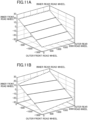
- FIGS. 11A and 11B are schematic views depicting the vehicle attitude in terms of an amount of expansion or contraction of a suspension of each road wheel, wherein: FIG. 11A is a view depicting the vehicle attitude when parallel rolling occurs, and FIG. 11B is a view depicting the vehicle attitude when diagonal roll occurs.
- a load shift occurs in the vehicle width direction of the vehicle in accordance with an increase in lateral acceleration thus increasing a roll angle.
- a pitch angle increases or decreases irrespective of an increase in roll angle. Accordingly, at the initial stage of turning, only a roll angle increases so that the parallel roll attitude as depicted in FIG. 11A is assumed and, thereafter, the forward inclined attitude or the rearward inclined attitude is assumed due to pitching which occurs irrespective of a roll angle.
- a reduction of driving force of the vehicle is started when the steering speed becomes equal to or greater than the threshold T S1 so that a pitch angle is increased in a direction that the front portion of the vehicle dips in synchronization with an increase in roll angle. Accordingly, at the initial stage of turning, rolling and pitching in which the front portion of the vehicle dips occur in synchronization with each other and hence, the diagonal roll attitude as depicted in FIG. 11B is assumed.
- a driving force reduction amount is promptly increased in a region at the initial stage of turning where the lateral acceleration is extremely small so that a situation in which the vehicle attitude may smoothly shift to a diagonal roll attitude is created when a driver starts a steering wheel operation.
- Such a configuration causes the cornering force of the front road wheels to increase thus improving responsivity of turning behavior and, at the same time, allows a driver to precisely recognize the generation and continuation of the turning behavior from that point.
- FIGS. 12A and 12B are diagrams depicting the manner of change in vertical load on the front road wheels during the above-mentioned turning traveling, wherein: FIG. 12A is a diagram depicting a change in vertical load on the inner front road wheel which is caused by a lateral load shift; and FIG. 12B is a diagram depicting a change in vertical load on the front road wheels which is caused by a deceleration of the vehicle.
- a reduction of driving force of the vehicle is started when the steering speed becomes equal to or greater than the threshold T S1 . Accordingly, deceleration also rises following the rise of the lateral acceleration so that the lateral acceleration and the deceleration vary while maintaining a linear relationship. Therefore, as indicated by the solid line in FIGS. 12A and 12B , in synchronization with a linear increase in amount of lateral load shift of the front road wheels in accordance with an increase in lateral acceleration, a longitudinal load shift is generated by deceleration thus increasing an amount of change in vertical load on the front road wheels from the rise (0 to 0.1 G) of the lateral acceleration.
Landscapes
- Engineering & Computer Science (AREA)
- Transportation (AREA)
- Mechanical Engineering (AREA)
- Chemical & Material Sciences (AREA)
- Combustion & Propulsion (AREA)
- Automation & Control Theory (AREA)
- Human Computer Interaction (AREA)
- Control Of Driving Devices And Active Controlling Of Vehicle (AREA)
- Control Of Vehicle Engines Or Engines For Specific Uses (AREA)
- Steering Control In Accordance With Driving Conditions (AREA)
Claims (3)
- Fahrzeugverhaltenssteuerungsvorrichtung (14), die auf ein Fahrzeug (1) mit einem lenkbaren vorderen Fahrbahnrad (2) angewendet wird, wobei die Fahrzeugverhaltenssteuerungsvorrichtung aufweist:ein Lenkgeschwindigkeitserfassungsteil (14), das konfiguriert ist, eine Lenkgeschwindigkeit des Fahrzeugs (1) zu erfassen;ein Antriebskraftverringerungs-Flag-Einstellteil (14), das konfiguriert ist, basierend auf der Lenkgeschwindigkeit ein Antriebskraftverringerungs-Flag festzulegen, welches angibt, ob eine Bedingung zum Zulassen einer Verringerung einer Antriebskraft des Fahrzeugs (1) erfüllt ist oder nicht; undein Antriebskraftverringerungsteil (14), das konfiguriert ist, basierend auf der Lenkgeschwindigkeit eine auf das Fahrzeug (1) aufzubringende zusätzliche Sollverzögerung zu erfassen, eine zum Erzielen der zusätzlichen Sollverzögerung benötigte Antriebskraftverringerungsmenge zu bestimmen, und mit der Verringerung der Antriebskraft des Fahrzeugs (1) zu beginnen, wenn das Antriebskraftverringerungs-Flag auf einen echten Wert festgelegt wird, der einen Zustand anzeigt, bei dem die Bedingung zum Zulassen einer Verringerung der Antriebskraft des Fahrzeugs (1) erfüllt ist,dadurch gekennzeichnet, dasswenn die Lenkgeschwindigkeit ansteigt, die zusätzliche Sollverzögerung derart ansteigt, dass sie näher an einem oberen Grenzwert von 0,5 m/s2 liegt.
- Fahrzeugverhaltenssteuerungsvorrichtung (14) nach Anspruch 1, wobei das Antriebskraftverringerungs-Flag-Einstellteil (14) konfiguriert ist, das Antriebskraftverringerungs-Flag auf den echten Wert festzulegen, wenn die Lenkgeschwindigkeit einen vorgegebenen Schwellenwert überschreitet.
- Fahrzeugverhaltenssteuerungsvorrichtung (14) nach Anspruch 1 oder 2, wobei das Antriebskraftverringerungsteil (14) konfiguriert ist, basierend auf der zusätzlichen Sollverzögerung eine zusätzliche Verzögerung unter einer Bedingung zu bestimmen, dass eine Änderungsrate der zusätzlichen Verzögerung kleiner gleich 0,5 m/s3 ist, und eine zum Erzielen der bestimmten zusätzlichen Verzögerung benötigte Antriebskraftverringerungsmenge zu bestimmen.
Applications Claiming Priority (2)
| Application Number | Priority Date | Filing Date | Title |
|---|---|---|---|
| JP2016086535A JP6202478B1 (ja) | 2016-04-22 | 2016-04-22 | 車両用挙動制御装置 |
| PCT/JP2017/013458 WO2017183415A1 (ja) | 2016-04-22 | 2017-03-30 | 車両用挙動制御装置 |
Publications (3)
| Publication Number | Publication Date |
|---|---|
| EP3418145A1 EP3418145A1 (de) | 2018-12-26 |
| EP3418145A4 EP3418145A4 (de) | 2019-11-06 |
| EP3418145B1 true EP3418145B1 (de) | 2023-03-08 |
Family
ID=59969351
Family Applications (1)
| Application Number | Title | Priority Date | Filing Date |
|---|---|---|---|
| EP17785757.0A Active EP3418145B1 (de) | 2016-04-22 | 2017-03-30 | Fahrzeugverhaltensteuerungsvorrichtung |
Country Status (5)
| Country | Link |
|---|---|
| US (1) | US10625731B2 (de) |
| EP (1) | EP3418145B1 (de) |
| JP (1) | JP6202478B1 (de) |
| CN (2) | CN108778874A (de) |
| WO (1) | WO2017183415A1 (de) |
Families Citing this family (8)
| Publication number | Priority date | Publication date | Assignee | Title |
|---|---|---|---|---|
| JP6481744B1 (ja) * | 2017-11-24 | 2019-03-13 | マツダ株式会社 | 四輪駆動車の制御装置 |
| JP6481745B1 (ja) * | 2017-11-24 | 2019-03-13 | マツダ株式会社 | 車両の制御装置 |
| JP6555327B2 (ja) * | 2017-11-24 | 2019-08-07 | マツダ株式会社 | 四輪駆動車の制御装置 |
| JP2019127095A (ja) * | 2018-01-23 | 2019-08-01 | マツダ株式会社 | 車両の制御装置 |
| JP6991466B2 (ja) | 2018-06-22 | 2022-01-12 | マツダ株式会社 | 車両制御システム及び方法 |
| JP7185218B2 (ja) * | 2018-09-10 | 2022-12-07 | マツダ株式会社 | 車両の制御方法、車両システム及び車両の制御装置 |
| JP7185219B2 (ja) * | 2018-09-10 | 2022-12-07 | マツダ株式会社 | 車両の制御方法、車両システム及び車両の制御装置 |
| JP7540360B2 (ja) * | 2021-02-17 | 2024-08-27 | マツダ株式会社 | 車両の制御システム |
Family Cites Families (27)
| Publication number | Priority date | Publication date | Assignee | Title |
|---|---|---|---|---|
| JP3784436B2 (ja) * | 1995-11-20 | 2006-06-14 | 本田技研工業株式会社 | 車両の制動力制御装置 |
| JP3747662B2 (ja) * | 1998-12-07 | 2006-02-22 | トヨタ自動車株式会社 | 車輌の運動制御装置 |
| AU2001271877A1 (en) * | 2000-07-06 | 2002-01-21 | Kelsey-Hayes Company | Traction control algorithm for vehicle operation upon deformable road surfaces |
| JP2002248966A (ja) | 2001-02-27 | 2002-09-03 | Mitsubishi Motors Corp | 車両用定速走行装置 |
| US7212901B2 (en) * | 2003-10-29 | 2007-05-01 | Nissan Motor Co., Ltd. | Lane departure prevention apparatus |
| JP4352864B2 (ja) * | 2003-11-12 | 2009-10-28 | 日産自動車株式会社 | 車両用旋回走行制御装置 |
| DE10356510A1 (de) * | 2003-12-03 | 2005-07-07 | Robert Bosch Gmbh | Fahrdynamikregelung mit vorgezogenem Druckaufbau am zu regelnden Rad |
| JP4929980B2 (ja) * | 2006-10-27 | 2012-05-09 | トヨタ自動車株式会社 | 車両走行制御装置 |
| JP2009101830A (ja) * | 2007-10-23 | 2009-05-14 | Toyota Motor Corp | 車両用制御装置 |
| JP2009120116A (ja) | 2007-11-16 | 2009-06-04 | Hitachi Ltd | 車両衝突回避支援装置 |
| JP5099221B2 (ja) * | 2008-05-19 | 2012-12-19 | 日産自動車株式会社 | 車両の旋回挙動制御装置/方法 |
| JP2010119204A (ja) * | 2008-11-12 | 2010-05-27 | Bridgestone Corp | 電気自動車の車両制御装置 |
| JP5193885B2 (ja) | 2009-01-13 | 2013-05-08 | 日立オートモティブシステムズ株式会社 | 車両の運動制御装置 |
| JP5471078B2 (ja) * | 2009-06-30 | 2014-04-16 | 株式会社アドヴィックス | 車両運動制御装置 |
| JP5265717B2 (ja) | 2011-03-10 | 2013-08-14 | 日立オートモティブシステムズ株式会社 | 車両の運動制御装置 |
| JP5700116B2 (ja) * | 2011-03-30 | 2015-04-15 | トヨタ自動車株式会社 | 車両の駆動力制御装置 |
| JP5724783B2 (ja) * | 2011-09-20 | 2015-05-27 | トヨタ自動車株式会社 | 車両の制御装置 |
| JP2013071524A (ja) | 2011-09-27 | 2013-04-22 | Toyota Motor Corp | 車両の制御装置 |
| JP5927054B2 (ja) | 2012-06-11 | 2016-05-25 | 日立オートモティブシステムズ株式会社 | 車両の走行制御装置 |
| JP5840112B2 (ja) * | 2012-11-09 | 2016-01-06 | 本田技研工業株式会社 | 車両挙動安定化制御装置 |
| JP6222472B2 (ja) * | 2014-08-11 | 2017-11-01 | マツダ株式会社 | 車両用挙動制御装置 |
| JP6112311B2 (ja) * | 2014-08-11 | 2017-04-12 | マツダ株式会社 | 車両用挙動制御装置 |
| JP6168480B2 (ja) * | 2015-09-30 | 2017-07-26 | マツダ株式会社 | エンジンの制御装置 |
| JP6194942B2 (ja) * | 2015-11-20 | 2017-09-13 | マツダ株式会社 | エンジンの制御装置 |
| JP6213904B1 (ja) * | 2016-06-30 | 2017-10-18 | マツダ株式会社 | 車両用挙動制御装置 |
| US10414400B2 (en) * | 2016-09-09 | 2019-09-17 | Mazda Motor Corporation | Control device for vehicle |
| JP6270251B1 (ja) * | 2016-09-21 | 2018-01-31 | マツダ株式会社 | 車両用挙動制御装置 |
-
2016
- 2016-04-22 JP JP2016086535A patent/JP6202478B1/ja active Active
-
2017
- 2017-03-30 WO PCT/JP2017/013458 patent/WO2017183415A1/ja not_active Ceased
- 2017-03-30 CN CN201780016206.5A patent/CN108778874A/zh active Pending
- 2017-03-30 US US16/084,246 patent/US10625731B2/en active Active
- 2017-03-30 EP EP17785757.0A patent/EP3418145B1/de active Active
- 2017-03-30 CN CN202411867862.4A patent/CN119389186A/zh active Pending
Also Published As
| Publication number | Publication date |
|---|---|
| JP6202478B1 (ja) | 2017-09-27 |
| EP3418145A1 (de) | 2018-12-26 |
| CN119389186A (zh) | 2025-02-07 |
| JP2017193316A (ja) | 2017-10-26 |
| US20190061739A1 (en) | 2019-02-28 |
| WO2017183415A1 (ja) | 2017-10-26 |
| EP3418145A4 (de) | 2019-11-06 |
| US10625731B2 (en) | 2020-04-21 |
| CN108778874A (zh) | 2018-11-09 |
Similar Documents
| Publication | Publication Date | Title |
|---|---|---|
| EP3418145B1 (de) | Fahrzeugverhaltensteuerungsvorrichtung | |
| EP3418149B1 (de) | Steuerungssystem für fahrzeugverhalten | |
| EP3418148B1 (de) | Fahrzeugverhaltensteuerungsvorrichtung | |
| US10793136B2 (en) | Vehicle behavior control device | |
| US9744967B2 (en) | Vehicle behavior control device | |
| US10266173B2 (en) | Vehicle behavior control device | |
| EP3741637A1 (de) | Verfahren zur steuerung eines fahrzeugs und fahrzeugsystem | |
| US10569765B2 (en) | Vehicle behavior control device | |
| US11136931B2 (en) | Vehicle control system | |
| JP2019123305A (ja) | 車両の制御装置 | |
| JP7026886B2 (ja) | 車両の制御装置 | |
| JP2019123304A (ja) | 車両の制御装置 | |
| JP2019093846A (ja) | 車両の制御装置 |
Legal Events
| Date | Code | Title | Description |
|---|---|---|---|
| STAA | Information on the status of an ep patent application or granted ep patent |
Free format text: STATUS: THE INTERNATIONAL PUBLICATION HAS BEEN MADE |
|
| PUAI | Public reference made under article 153(3) epc to a published international application that has entered the european phase |
Free format text: ORIGINAL CODE: 0009012 |
|
| STAA | Information on the status of an ep patent application or granted ep patent |
Free format text: STATUS: REQUEST FOR EXAMINATION WAS MADE |
|
| 17P | Request for examination filed |
Effective date: 20180919 |
|
| AK | Designated contracting states |
Kind code of ref document: A1 Designated state(s): AL AT BE BG CH CY CZ DE DK EE ES FI FR GB GR HR HU IE IS IT LI LT LU LV MC MK MT NL NO PL PT RO RS SE SI SK SM TR |
|
| AX | Request for extension of the european patent |
Extension state: BA ME |
|
| DAV | Request for validation of the european patent (deleted) | ||
| DAX | Request for extension of the european patent (deleted) | ||
| A4 | Supplementary search report drawn up and despatched |
Effective date: 20191007 |
|
| RIC1 | Information provided on ipc code assigned before grant |
Ipc: B62D 113/00 20060101ALI20190930BHEP Ipc: B60W 10/04 20060101AFI20190930BHEP Ipc: B60W 10/20 20060101ALI20190930BHEP Ipc: B62D 101/00 20060101ALI20190930BHEP Ipc: B62D 6/00 20060101ALI20190930BHEP Ipc: B60K 28/02 20060101ALI20190930BHEP Ipc: B62D 137/00 20060101ALI20190930BHEP Ipc: B60W 30/02 20120101ALI20190930BHEP |
|
| GRAP | Despatch of communication of intention to grant a patent |
Free format text: ORIGINAL CODE: EPIDOSNIGR1 |
|
| STAA | Information on the status of an ep patent application or granted ep patent |
Free format text: STATUS: GRANT OF PATENT IS INTENDED |
|
| INTG | Intention to grant announced |
Effective date: 20221031 |
|
| GRAS | Grant fee paid |
Free format text: ORIGINAL CODE: EPIDOSNIGR3 |
|
| GRAA | (expected) grant |
Free format text: ORIGINAL CODE: 0009210 |
|
| STAA | Information on the status of an ep patent application or granted ep patent |
Free format text: STATUS: THE PATENT HAS BEEN GRANTED |
|
| AK | Designated contracting states |
Kind code of ref document: B1 Designated state(s): AL AT BE BG CH CY CZ DE DK EE ES FI FR GB GR HR HU IE IS IT LI LT LU LV MC MK MT NL NO PL PT RO RS SE SI SK SM TR |
|
| REG | Reference to a national code |
Ref country code: GB Ref legal event code: FG4D |
|
| REG | Reference to a national code |
Ref country code: CH Ref legal event code: EP Ref country code: AT Ref legal event code: REF Ref document number: 1552404 Country of ref document: AT Kind code of ref document: T Effective date: 20230315 |
|
| REG | Reference to a national code |
Ref country code: IE Ref legal event code: FG4D |
|
| REG | Reference to a national code |
Ref country code: DE Ref legal event code: R096 Ref document number: 602017066658 Country of ref document: DE |
|
| REG | Reference to a national code |
Ref country code: LT Ref legal event code: MG9D |
|
| REG | Reference to a national code |
Ref country code: NL Ref legal event code: MP Effective date: 20230308 |
|
| PG25 | Lapsed in a contracting state [announced via postgrant information from national office to epo] |
Ref country code: RS Free format text: LAPSE BECAUSE OF FAILURE TO SUBMIT A TRANSLATION OF THE DESCRIPTION OR TO PAY THE FEE WITHIN THE PRESCRIBED TIME-LIMIT Effective date: 20230308 Ref country code: NO Free format text: LAPSE BECAUSE OF FAILURE TO SUBMIT A TRANSLATION OF THE DESCRIPTION OR TO PAY THE FEE WITHIN THE PRESCRIBED TIME-LIMIT Effective date: 20230608 Ref country code: LV Free format text: LAPSE BECAUSE OF FAILURE TO SUBMIT A TRANSLATION OF THE DESCRIPTION OR TO PAY THE FEE WITHIN THE PRESCRIBED TIME-LIMIT Effective date: 20230308 Ref country code: LT Free format text: LAPSE BECAUSE OF FAILURE TO SUBMIT A TRANSLATION OF THE DESCRIPTION OR TO PAY THE FEE WITHIN THE PRESCRIBED TIME-LIMIT Effective date: 20230308 Ref country code: HR Free format text: LAPSE BECAUSE OF FAILURE TO SUBMIT A TRANSLATION OF THE DESCRIPTION OR TO PAY THE FEE WITHIN THE PRESCRIBED TIME-LIMIT Effective date: 20230308 Ref country code: ES Free format text: LAPSE BECAUSE OF FAILURE TO SUBMIT A TRANSLATION OF THE DESCRIPTION OR TO PAY THE FEE WITHIN THE PRESCRIBED TIME-LIMIT Effective date: 20230308 |
|
| REG | Reference to a national code |
Ref country code: AT Ref legal event code: MK05 Ref document number: 1552404 Country of ref document: AT Kind code of ref document: T Effective date: 20230308 |
|
| PG25 | Lapsed in a contracting state [announced via postgrant information from national office to epo] |
Ref country code: SE Free format text: LAPSE BECAUSE OF FAILURE TO SUBMIT A TRANSLATION OF THE DESCRIPTION OR TO PAY THE FEE WITHIN THE PRESCRIBED TIME-LIMIT Effective date: 20230308 Ref country code: NL Free format text: LAPSE BECAUSE OF FAILURE TO SUBMIT A TRANSLATION OF THE DESCRIPTION OR TO PAY THE FEE WITHIN THE PRESCRIBED TIME-LIMIT Effective date: 20230308 Ref country code: GR Free format text: LAPSE BECAUSE OF FAILURE TO SUBMIT A TRANSLATION OF THE DESCRIPTION OR TO PAY THE FEE WITHIN THE PRESCRIBED TIME-LIMIT Effective date: 20230609 Ref country code: FI Free format text: LAPSE BECAUSE OF FAILURE TO SUBMIT A TRANSLATION OF THE DESCRIPTION OR TO PAY THE FEE WITHIN THE PRESCRIBED TIME-LIMIT Effective date: 20230308 |
|
| PG25 | Lapsed in a contracting state [announced via postgrant information from national office to epo] |
Ref country code: SM Free format text: LAPSE BECAUSE OF FAILURE TO SUBMIT A TRANSLATION OF THE DESCRIPTION OR TO PAY THE FEE WITHIN THE PRESCRIBED TIME-LIMIT Effective date: 20230308 Ref country code: RO Free format text: LAPSE BECAUSE OF FAILURE TO SUBMIT A TRANSLATION OF THE DESCRIPTION OR TO PAY THE FEE WITHIN THE PRESCRIBED TIME-LIMIT Effective date: 20230308 Ref country code: PT Free format text: LAPSE BECAUSE OF FAILURE TO SUBMIT A TRANSLATION OF THE DESCRIPTION OR TO PAY THE FEE WITHIN THE PRESCRIBED TIME-LIMIT Effective date: 20230710 Ref country code: EE Free format text: LAPSE BECAUSE OF FAILURE TO SUBMIT A TRANSLATION OF THE DESCRIPTION OR TO PAY THE FEE WITHIN THE PRESCRIBED TIME-LIMIT Effective date: 20230308 Ref country code: CZ Free format text: LAPSE BECAUSE OF FAILURE TO SUBMIT A TRANSLATION OF THE DESCRIPTION OR TO PAY THE FEE WITHIN THE PRESCRIBED TIME-LIMIT Effective date: 20230308 Ref country code: AT Free format text: LAPSE BECAUSE OF FAILURE TO SUBMIT A TRANSLATION OF THE DESCRIPTION OR TO PAY THE FEE WITHIN THE PRESCRIBED TIME-LIMIT Effective date: 20230308 |
|
| REG | Reference to a national code |
Ref country code: CH Ref legal event code: PL |
|
| PG25 | Lapsed in a contracting state [announced via postgrant information from national office to epo] |
Ref country code: SK Free format text: LAPSE BECAUSE OF FAILURE TO SUBMIT A TRANSLATION OF THE DESCRIPTION OR TO PAY THE FEE WITHIN THE PRESCRIBED TIME-LIMIT Effective date: 20230308 Ref country code: PL Free format text: LAPSE BECAUSE OF FAILURE TO SUBMIT A TRANSLATION OF THE DESCRIPTION OR TO PAY THE FEE WITHIN THE PRESCRIBED TIME-LIMIT Effective date: 20230308 Ref country code: IS Free format text: LAPSE BECAUSE OF FAILURE TO SUBMIT A TRANSLATION OF THE DESCRIPTION OR TO PAY THE FEE WITHIN THE PRESCRIBED TIME-LIMIT Effective date: 20230708 |
|
| REG | Reference to a national code |
Ref country code: BE Ref legal event code: MM Effective date: 20230331 |
|
| REG | Reference to a national code |
Ref country code: DE Ref legal event code: R097 Ref document number: 602017066658 Country of ref document: DE |
|
| PG25 | Lapsed in a contracting state [announced via postgrant information from national office to epo] |
Ref country code: LU Free format text: LAPSE BECAUSE OF NON-PAYMENT OF DUE FEES Effective date: 20230330 |
|
| PLBE | No opposition filed within time limit |
Free format text: ORIGINAL CODE: 0009261 |
|
| STAA | Information on the status of an ep patent application or granted ep patent |
Free format text: STATUS: NO OPPOSITION FILED WITHIN TIME LIMIT |
|
| PG25 | Lapsed in a contracting state [announced via postgrant information from national office to epo] |
Ref country code: MC Free format text: LAPSE BECAUSE OF FAILURE TO SUBMIT A TRANSLATION OF THE DESCRIPTION OR TO PAY THE FEE WITHIN THE PRESCRIBED TIME-LIMIT Effective date: 20230308 |
|
| REG | Reference to a national code |
Ref country code: IE Ref legal event code: MM4A |
|
| PG25 | Lapsed in a contracting state [announced via postgrant information from national office to epo] |
Ref country code: SI Free format text: LAPSE BECAUSE OF FAILURE TO SUBMIT A TRANSLATION OF THE DESCRIPTION OR TO PAY THE FEE WITHIN THE PRESCRIBED TIME-LIMIT Effective date: 20230308 Ref country code: MC Free format text: LAPSE BECAUSE OF FAILURE TO SUBMIT A TRANSLATION OF THE DESCRIPTION OR TO PAY THE FEE WITHIN THE PRESCRIBED TIME-LIMIT Effective date: 20230308 Ref country code: LI Free format text: LAPSE BECAUSE OF NON-PAYMENT OF DUE FEES Effective date: 20230331 Ref country code: IE Free format text: LAPSE BECAUSE OF NON-PAYMENT OF DUE FEES Effective date: 20230330 Ref country code: DK Free format text: LAPSE BECAUSE OF FAILURE TO SUBMIT A TRANSLATION OF THE DESCRIPTION OR TO PAY THE FEE WITHIN THE PRESCRIBED TIME-LIMIT Effective date: 20230308 Ref country code: CH Free format text: LAPSE BECAUSE OF NON-PAYMENT OF DUE FEES Effective date: 20230331 |
|
| 26N | No opposition filed |
Effective date: 20231211 |
|
| GBPC | Gb: european patent ceased through non-payment of renewal fee |
Effective date: 20230608 |
|
| PG25 | Lapsed in a contracting state [announced via postgrant information from national office to epo] |
Ref country code: BE Free format text: LAPSE BECAUSE OF NON-PAYMENT OF DUE FEES Effective date: 20230331 |
|
| PG25 | Lapsed in a contracting state [announced via postgrant information from national office to epo] |
Ref country code: GB Free format text: LAPSE BECAUSE OF NON-PAYMENT OF DUE FEES Effective date: 20230608 |
|
| PG25 | Lapsed in a contracting state [announced via postgrant information from national office to epo] |
Ref country code: IT Free format text: LAPSE BECAUSE OF FAILURE TO SUBMIT A TRANSLATION OF THE DESCRIPTION OR TO PAY THE FEE WITHIN THE PRESCRIBED TIME-LIMIT Effective date: 20230308 Ref country code: FR Free format text: LAPSE BECAUSE OF NON-PAYMENT OF DUE FEES Effective date: 20230508 |
|
| PG25 | Lapsed in a contracting state [announced via postgrant information from national office to epo] |
Ref country code: BG Free format text: LAPSE BECAUSE OF FAILURE TO SUBMIT A TRANSLATION OF THE DESCRIPTION OR TO PAY THE FEE WITHIN THE PRESCRIBED TIME-LIMIT Effective date: 20230308 |
|
| PG25 | Lapsed in a contracting state [announced via postgrant information from national office to epo] |
Ref country code: BG Free format text: LAPSE BECAUSE OF FAILURE TO SUBMIT A TRANSLATION OF THE DESCRIPTION OR TO PAY THE FEE WITHIN THE PRESCRIBED TIME-LIMIT Effective date: 20230308 |
|
| PG25 | Lapsed in a contracting state [announced via postgrant information from national office to epo] |
Ref country code: CY Free format text: LAPSE BECAUSE OF FAILURE TO SUBMIT A TRANSLATION OF THE DESCRIPTION OR TO PAY THE FEE WITHIN THE PRESCRIBED TIME-LIMIT; INVALID AB INITIO Effective date: 20170330 |
|
| PG25 | Lapsed in a contracting state [announced via postgrant information from national office to epo] |
Ref country code: HU Free format text: LAPSE BECAUSE OF FAILURE TO SUBMIT A TRANSLATION OF THE DESCRIPTION OR TO PAY THE FEE WITHIN THE PRESCRIBED TIME-LIMIT; INVALID AB INITIO Effective date: 20170330 |
|
| PG25 | Lapsed in a contracting state [announced via postgrant information from national office to epo] |
Ref country code: TR Free format text: LAPSE BECAUSE OF FAILURE TO SUBMIT A TRANSLATION OF THE DESCRIPTION OR TO PAY THE FEE WITHIN THE PRESCRIBED TIME-LIMIT Effective date: 20230308 |
|
| PGFP | Annual fee paid to national office [announced via postgrant information from national office to epo] |
Ref country code: DE Payment date: 20260204 Year of fee payment: 10 |