EP3418436B1 - Schlauchvorrichtung und anordnung - Google Patents
Schlauchvorrichtung und anordnung Download PDFInfo
- Publication number
- EP3418436B1 EP3418436B1 EP17177250.2A EP17177250A EP3418436B1 EP 3418436 B1 EP3418436 B1 EP 3418436B1 EP 17177250 A EP17177250 A EP 17177250A EP 3418436 B1 EP3418436 B1 EP 3418436B1
- Authority
- EP
- European Patent Office
- Prior art keywords
- hose
- pressure
- water
- sectional area
- corrugated hose
- Prior art date
- Legal status (The legal status is an assumption and is not a legal conclusion. Google has not performed a legal analysis and makes no representation as to the accuracy of the status listed.)
- Active
Links
Images


Classifications
-
- A—HUMAN NECESSITIES
- A47—FURNITURE; DOMESTIC ARTICLES OR APPLIANCES; COFFEE MILLS; SPICE MILLS; SUCTION CLEANERS IN GENERAL
- A47L—DOMESTIC WASHING OR CLEANING; SUCTION CLEANERS IN GENERAL
- A47L15/00—Washing or rinsing machines for crockery or tableware
- A47L15/42—Details
- A47L15/4214—Water supply, recirculation or discharge arrangements; Devices therefor
- A47L15/4217—Fittings for water supply, e.g. valves or plumbing means to connect to cold or warm water lines, aquastops
-
- D—TEXTILES; PAPER
- D06—TREATMENT OF TEXTILES OR THE LIKE; LAUNDERING; FLEXIBLE MATERIALS NOT OTHERWISE PROVIDED FOR
- D06F—LAUNDERING, DRYING, IRONING, PRESSING OR FOLDING TEXTILE ARTICLES
- D06F39/00—Details of washing machines not specific to a single type of machines covered by groups D06F9/00 - D06F27/00
- D06F39/08—Liquid supply or discharge arrangements
- D06F39/081—Safety arrangements for preventing water damage
Definitions
- the present invention relates to a hose device and an arrangement with a water-conducting household appliance and a hose device of this type.
- Household appliances that carry water are usually connected to a water supply network with the aid of a hose device in order to supply them with fresh water. It is common to do so, such as the EP 2 314 752 A1 shows that such hose devices are provided as double-walled systems with an inner and outer hose. The annular space formed between the inner and outer hose is connected in a fluid-conducting manner to a sensor in the base of the household appliance. It can therefore detect a leak of water from the inner tube into the annulus. Such hose devices also have a blocking device which is designed to block a water supply to the inner hose in the event of a detected leak.
- a disadvantage of hose devices in EP 2 314 752 A1 described type is that they have a comparatively complex structure and are correspondingly complex and costly to manufacture.
- the EP 0 819 918 A2 Figure 12 shows a fluid control system in which a control device is provided for closing a fluid passage in order to achieve pressure regulation, the control device being intended to be integrated or used in a line which is part of a hydraulic device.
- an inner hose that conducts fresh water should be suitable for drinking water, as special hygiene requirements must be observed. Such requirements can result from legal regulations and are subject to corresponding change. As a result, the choice of material for hoses that conduct fresh water can be restricted. Furthermore, this can have the consequence that hose materials are used which have a reduced strength.
- a hose device for a water-carrying household appliance with a first connection for a connection to a water supply network, a second connection for a connection to the household appliance, precisely one hose, which is arranged between the first connection and the second connection, the hose is designed as a single-walled corrugated hose and is set up to supply water to the household appliance, and a pressure reducer which is set up to reduce pressure surges from the water supply network into the corrugated hose.
- the hose device has only a single (that is, not about double-walled hose or two, three or more hoses) hose, a simple and inexpensive hose device can be provided.
- no hose - in particular neither corrugated nor smooth hose - is provided between the first and second connection.
- the pressure reducer is arranged in front of the corrugated hose in the direction of flow. The probability of a leak is therefore greatly reduced, so that no additional external hose is necessary to catch the leakage liquid.
- Such pressure reducers are not known from the prior art in this context. This differs from so-called flow reducers, such as in EP 2 314 752 A1 described, whose only task is to reduce the flow during operation to a certain volume flow. However, these are not able to reduce high pressure surges in the pipeline network to a level that avoids leaks in the corrugated hose.
- the water-carrying household appliance is, for example, a household dishwasher or household washing machine.
- the water supply network includes, for example, a tap with an external thread and provides water with a nominal pressure of, for example, 3 to 7 bar, in particular 5 or 6 bar.
- the first connection comprises, for example, a nut with an internal thread for screwing onto the external thread of the tap.
- the first connection comprises a connector on which the nut is rotatably mounted.
- the connector can comprise, for example, a connecting section which protrudes into a first connecting section of the corrugated hose and is connected to it.
- the first connection can comprise a sieve for filtering water.
- the second connection comprises a connector and a nut rotatably mounted on the connector with an internal thread for screwing onto a connection element of the domestic appliance with an external thread.
- the connector of the second connection can include a curved section, in particular by 90 °, in order to enable a space-saving connection to the household appliance, since the connection element of the household appliance together with the household appliance can be arranged correspondingly closer to a wall.
- the connector of the second connection comprises a connecting section which, for example, protrudes into a second connecting section of the corrugated hose and is connected to it.
- a “single-walled hose” means a hose which comprises a simple wall and is in particular formed in one piece, in one piece or in one piece of material.
- “Corrugated hose” means in the present case a hose that comprises wave crests and wave troughs which alternate along a direction of extent of the corrugated hose.
- the first and / or the second connection section can be smooth (that is, not corrugated) or corrugated in sections.
- the corrugated hose is designed as a water-carrying corrugated hose.
- the corrugated hose is set up to conduct or conduct water on its corrugated inside.
- a corrugated outside of the corrugated hose is set up to delimit the corrugated hose and any water located therein from the surroundings of the household appliance.
- a corrugated outside of the corrugated hose faces an environment of the household appliance or an external environment.
- the outer surface of the corrugated hose forms part of an outermost surface of the hose device. In the case of a hole in the corrugated hose, the fresh water would thus get into the vicinity of the household appliance, in particular on the floor of a building.
- Corrugated hoses have the advantage that they can be bent more easily and that damage due to kinks rarely occurs.
- the corrugated hose creates a fluid connection between the first connection and the second connection.
- the pressure reducer is a device which, in particular, effectively dampens pressure surges from the pipe network, so that the corrugated hose is protected. Furthermore, the pressure reducer is set up, for example, to abruptly reduce a flow cross-section when a pressure surge occurs in the water supply network, in order to reduce the pressure surge in the corrugated hose.
- the pressure reducer is set up to reduce a pressure of a pressure surge in the corrugated hose to below 50%, 40% or 30% of the To reduce the pressure of the corresponding pressure surge in the water supply network and / or to reduce a pressure of a pressure surge in the corrugated hose to below 15, 12, 10, 8 or 6 bar.
- the corrugated hose can be manufactured with a correspondingly reduced wall thickness.
- the hose device between the first connection and the corrugated hose is designed without a safety valve for shutting off a flow of water into the corrugated hose in the event of a leak from the latter.
- the hose device does not include a safety device with a safety valve for shutting off the flow of water. In this way, a particularly inexpensive and yet reliable hose device can be provided.
- the pressure reducer comprises a control element which is set up to reduce a flow cross section for reducing pressure surges in the corrugated hose by means of an elastic movement and / or axial movement.
- the pressure reducer is arranged, for example, inside the first connection.
- the elastic movement and / or axial movement is triggered by means of the pressure output.
- a mass flow and thereby the pressure can be suddenly reduced.
- the pressure reducer is set up to form a plurality of radial channels by means of the elastic and / or axial movement when the pressure surge occurs in the water supply network and thereby to reduce the pressure surge in the corrugated hose.
- the radial channels by means of the elastic movement or elastic deformation.
- control element comprises a disc which is designed to be elastically deformable.
- the disk is made, for example, partially or completely from silicone and / or from an elastomer material.
- silicone and / or an elastomer material is well suited for drinking water or drinking water approval.
- the disk comprises a flat and ring-shaped side against which fresh water flows, so that an elastic deformation and / or an axial movement of the disk takes place.
- the pressure reducer comprises inner and outer openings for the passage of water to the corrugated hose.
- the regulating element is preferably set up to merely reduce and / or prevent a flow of water through the outer openings in order to reduce pressure surges in the corrugated hose.
- the pressure reducer comprises a disk section and a tube section molded onto the disk section.
- a fluid channel which is axially delimited by a wall of the disk section, is preferably formed within the tube section and the disk section.
- the wall here comprises the inner openings which are arranged radially inside the fluid channel.
- the disk section comprises a disk wall which is arranged radially outside of the tube section and which comprises the outer openings.
- control element is provided so that it can move elastically with respect to the pane wall and is arranged on the pipe section opposite the pane wall.
- the regulating element is designed to be pressed against the pane wall in order to at least partially close the outer openings close.
- the pressure reducer is provided in the first connection, for example, in such a way that the water from the water supply network has to flow through the inner and / or outer openings in order to get into the corrugated hose. As a result, the control element is forced by the water, so that the function of the pressure reducer is always guaranteed.
- the pressure reducer is screwed into the first connection by means of a thread.
- an external thread is provided in an outer region of the disk section, which can be screwed into an internal thread which is provided within the first connection. This ensures a simple and reliable connection between the pressure reducer and the first connection.
- the corrugated hose is made partially or completely from polyethylene.
- the polyethylene is designed as cross-linked polyethylene (PE-X).
- PE-X cross-linked polyethylene
- Polyethylene is particularly suitable for use in drinking water.
- the corrugated hose can thereby be manufactured inexpensively.
- the strength disadvantages of polyethylene can be accepted because the pressure reducer is used.
- the first connection is, in particular exclusively, connected to the corrugated hose by means of a plug-in connection and / or a non-positive connection, in particular cold-pressed.
- the plug connection is formed in that the connection section of the connector is inserted into the first connection section of the corrugated pipe or the connection section of the corrugated hose is slipped over the connection section of the connector. In particular takes place this with the help of a mounting device.
- the connecting section of the corrugated hose prior to being connected to the connecting section of the connector, has an inside diameter that is smaller than an outside diameter of the connecting section of the connector.
- crosslinked polyethylene has a resilience such that after expansion (without the supply of external heat) it is pretensioned to the corresponding initial state.
- the non-positive connection is formed, for example, by the radial force due to the resetting behavior of the connecting section of the corrugated hose on the connecting section of the connector, so that an axial fixation is ensured in particular due to friction (referred to here as "cold pressing").
- the plug connection is preferably set up to withstand water pressures that are greater than 10, 12 or 15 bar.
- the first connection comprises an inlet cross-sectional area for a water inlet and an outlet cross-sectional area for a water outlet, the inlet cross-sectional area being at least 9, 12, 15 or 20 times larger than the outlet cross-sectional area.
- the connector of the first connection tapers.
- the pressure reducer fails (due to malfunction or component failure)
- the pressure reduction is achieved with the aid of the cross-sectional taper.
- an additional pressure-reducing effect is achieved when pressure surges occur.
- the inlet cross-sectional area and the outlet cross-sectional area are circular and a diameter of the inlet cross-sectional area is at least 3, 4, 4.5 or 5 times larger than a diameter of the outlet cross-sectional area.
- the connector of the first connection is rotationally symmetrical.
- the first connection is designed as a straight connection that does not change the direction of flow of the fresh water.
- the diameter of the inlet cross-sectional area is between 16 and 20 mm or 17 and 19 mm, in particular 18 mm, and / or the diameter of the outlet cross-sectional area is between 3 and 5 mm, in particular 4 mm.
- the outlet cross-sectional area is formed on the connecting section of the connector of the first connection.
- the inlet cross-sectional area is preferably formed on the nut of the first connection.
- the corrugated hose has an inside diameter between 6 and 10 mm or 7 and 9 mm, in particular 8 mm.
- only the household appliance has one or more valves.
- hose device does not have a blocking device which is designed to block the inflow of fresh water into the corrugated hose. Only the household appliance has valves that are set up to block an inflow of water.
- hose device and / or the arrangement also include combinations, which are not explicitly mentioned, of features or embodiments described above or below with regard to the exemplary embodiments.
- the person skilled in the art will also add individual aspects as improvements or additions to the respective basic shape of the hose device and / or the arrangement.
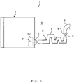
- Fig. 1 shows an arrangement 1 with a water-carrying household appliance 2, in particular a household dishwasher, and a hose device 3.
- the hose device 3 comprises a first connection 4 which is connected to a water supply network 5, in particular a tap or faucet of the water supply network 5.
- the hose device 3 comprises a second connection 6, which is connected to a connection element 7 of the domestic appliance 2.
- the first connection 4 and the second connection 6 are connected to one another by means of a single-walled hose 8.
- the hose 8 is the only hose between the connections 4, 6 and is also not double-walled.
- the single-walled hose 8 thus creates a fluid connection between the water supply network 5 and the household appliance 2.
- the hose 8 is designed as a corrugated hose.
- the hose device 3 is formed between the first connection 4 and the corrugated hose 8 without a safety valve for shutting off a flow of water into the corrugated hose 8 in the event of a leak from the latter.
- a pressure reducer 10 (shown in dashed lines) is provided within the first connection 4 in order to reduce pressure surges 11 (in Fig. 2 shown) from the water supply network 5 to reduce in the corrugated hose 8.
- the corrugated hose 8 can be protected and a safety valve in the hose device 3 can be dispensed with. Only the household appliance 2 has at least one valve 50 in order to interrupt a flow of fresh water into the household appliance 2.
- the household appliance 2 could also be designed as a washing machine, coffee machine or water dispenser.
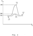
- Fig. 2 shows a schematic pressure-time diagram.
- a pressure P is plotted over a time t.
- a qualitative pressure curve 12 which is present on the water pipe network 5, is shown.
- the pressure curve 12 has a sudden increase in pressure, namely a pressure surge 11.
- the pressure surge 11 has, for example, a brief peak pressure PM greater than 15, 20, 30, 40 or 60 bar.
- a nominal pressure PN is clearly exceeded, for example by a factor of 5, 7 or 10.
- the nominal pressure PN is, for example, between 3 and 7 bar, in particular 5 or 6 bar.
- a pressure profile 13 which is present inside the corrugated hose 8, is plotted over time t. It can be seen here that only a slight increase in pressure 14 occurs in the corrugated hose 8 due to the pressure surge 11.
- the pressure reducer 10 is set up to reduce a pressure PW of the pressure surge 14 in the corrugated hose 8 to below 50%, 40% or 30% of the peak pressure PM of the corresponding pressure surge 11 in the water pipe network 5 and / or the pressure PW of the pressure surge 14 in the corrugated hose 8 to below 30, 20, 15, 12, 10, 8 or 6 bar.
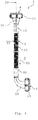
- Fig. 3 shows the hose device 3, in particular from FIG Fig. 1 , in a side view.
- the first connection 4 comprises a nut 15 which is rotatably mounted on a connector 16 of the first connection 4.
- the nut 15 comprises an internal thread (not shown) which can be screwed onto an external thread of a tap of the water supply network 5.
- the connector 16 is connected to a connecting section 17 of the corrugated hose 8.
- a Such a connection is designed, for example, as a plug connection and / or a non-positive connection.
- the connector 16 is connected to the connecting section 17 by means of cold pressing.
- the second connection 6 comprises a nut 18 which is rotatably mounted on a connector 19 of the second connection 6.
- the connector 19 is connected to a connecting section 20 of the corrugated hose 8.
- Such a connection can also be designed as a plug connection and / or a non-positive connection.
- the connector 19 is connected to the connecting section 20 by means of cold pressing.
- a corrugated section 21 of the corrugated hose 8 is formed between the connecting sections 17, 20.
- the two connecting sections 17, 20 are integrally formed on the corrugated section 21.
- the corrugated section 21 includes wave crests and wave troughs (see reference numerals 26 and 27 in Fig. 4 ), which alternate along an extension direction of the corrugated section 21 or the flow direction R1.
- a corrugated contour is formed both on an inside 28 of the corrugated hose 8, which comes into contact with the fresh water, and on an outside 29, which faces the surroundings 9.
- the connector 16 of the first connection is essentially rotationally symmetrical.
- the connector 19 of the second connection 6 has a curvature of approximately 90 °.
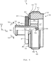
- Fig. 4 shows section IV Fig. 3 .
- the connector 16 comprises a base section 22 which tapers and to which a connecting section 23 connects, which engages in the connecting section 17 of the corrugated hose 8.
- the connecting section 23 is formed in one piece with the base section 22. Furthermore, the connecting section 23 has a tubular shape with a constant inner diameter D2.
- the connecting sections 17 and 23 are firmly connected to one another by means of cold pressing.
- the connector 16 further comprises an annular projection 24 which positively engages in a recess in the nut 15.
- the pressure reducer 10 (in Fig. 4 shown only schematically) is arranged within the base section 22.
- a flow direction R1 of the fresh water points from the nut 15 to the corrugated section 21.
- a sieve 25 is arranged in front of the pressure reducer 10 in the flow direction R1. The sieve 25 filters the water before it can get into the corrugated hose 8.
- the nut 15 comprises an inlet cross-sectional area A1 for a water inlet
- the connecting section 23 comprises an outlet cross-sectional area A2 for a water outlet
- the inlet cross-sectional area A1 being at least 9, 12, 15 or 20 times larger than the outlet cross-sectional area A2.
- the inlet cross-sectional area A1 and the outlet cross-sectional area A2 are circular, with a diameter D1 of the inlet cross-sectional area A1 being at least 3, 4, 4, 5 or 5 times larger than a diameter D2 of the outlet cross-sectional area A2.
- the diameter D1 of the inlet cross-sectional area A1 is between 16 and 20 mm or 17 and 19 mm, in particular 18 mm, and / or the diameter D2 of the outlet cross-sectional area A2 is between 3 and 5 mm, in particular 4 mm.
- Such a taper, in particular of the base section 22, can achieve an additional reduction in pressure surges 11 or an alternative reduction in pressure surges in the event of a malfunction of the pressure reducer 10.
- An inside diameter d3 of the corrugated hose 8 is between 6 and 10 mm or 7 and 9 mm, in particular 8 mm.
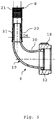
- Fig. 5 shows an in Fig. 3 section, not shown, which runs through the second connection 6 and a section of the corrugated hose 8 adjacent thereto.
- the connector 19 comprises a base section 30, onto which a tubular connecting section 31 with a substantially constant inner diameter D4 is formed, which protrudes into the connecting section 20 of the corrugated hose 8.
- the inside diameter D4 is, for example, between 3 and 5 mm, in particular 4 mm.
- a connection between the connecting sections 20, 31 is designed as a plug connection and / or a force-fit connection.
- the connecting sections 20, 31 are connected to one another by means of cold pressing.
- an annular projection 32 is integrally formed on the base section 30, which protrusion engages in a recess in the nut 18 so that the nut 18 can be rotated relative to the connector 19.
- the base section 30 is curved by 90 °, so that water which flows through the base section 30 changes direction by 90 °. Furthermore, the base section 30 widens from the connecting section 31 towards the nut 18.
- Fig. 6 shows the, especially in Fig. 1 indicated, pressure reducer 10 in a half section.
- the pressure reducer 10 comprises a disk section 33 with a disk wall 51 which extends in a radial direction R2.
- the radial direction R2 runs perpendicular to the flow direction R1.
- a tube section 34 is formed on the disk section 33 and extends counter to the flow direction R1.
- an annular projection 35 is provided, which protrudes in the radial direction R2.
- the disk section 33 has a disk-shaped recess 37 on a side 36 facing away from the tube section 34.
- the disk wall 51 has an outer through opening 38 which runs in the flow direction R1 and is provided radially outside of the pipe section 34.
- the outer through opening 38 runs from a side 39 of the disk section 33 facing the tube section 34 to the side 36.
- the outer through opening 38 opens into the recess 37.
- An annular section 40 is formed on the disk wall 51, which is arranged radially outside the through openings 38 and extends against the flow direction R1.
- an external thread 41 is provided on a radially outer side 42 of the disk section 33 on the disk wall 51.
- a channel 43 runs through the pipe section 34 to the disk section 33, a wall 44 of the disk section 33 separating the channel 43 from the recess 37.
- the wall 44 comprises an inner opening 45 which runs in the flow direction R1 and creates a fluid connection between the channel 43 and the recess 37.
- the inner opening 45 is arranged radially inside the tube section 34.
- the disk wall 51 can comprise a plurality of outer openings 38 for the passage of water to the corrugated hose 8.
- the wall 44 can comprise a multiplicity of inner openings 45 for the passage of water to the corrugated hose 8.
- the channel 43 has a flow cross section A3.
- the inner opening 45 or all inner openings 45 (in the case of several) has / have a flow cross section A4.
- the flow cross section A3 is significantly larger than the flow cross section A4, so that water flowing from the channel 43 into the inner opening 45 or inner openings 45 has to overcome a reduction in the flow cross section.
- a regulating element 46 is arranged on the ring section 34. As in Fig. 6 is shown, the control element 46 is arranged on the side 39 of the disk portion 33. A circumferential flow cross-sectional area A5 is formed between the regulating element 46 and a surface 47 of the ring section 40 that faces the regulating element 46. Water that flows around the pipe section 34 and the regulating element 46 (indicated by parallel arrows 52) must pass through the flow cross-section A5 in order to reach the opening 38 and to flow through it.
- the regulating element 46 is designed to reduce the flow cross section A5 within the first connection 4 in order to reduce pressure surges 14 in the corrugated hose 8 by means of an elastic movement and / or axial movement.
- the control element 46 is designed as a disk that is designed to be elastically deformable and axially movable. By means of an elastic deformation and / or axial movement of the control element 46 in the flow direction R1, the control element 46 is pressed against the surface 47, so that the flow cross-section A5 is also reduced.
- the regulating element 46 comprises, for example, silicone and / or a ceramic material.
- the regulating element 46 is designed in particular to reduce and / or prevent a flow of water through the outer openings 38 in order to reduce pressure surges 11 in the corrugated hose.
- the pressure reducer 10 is screwed into the first connection 4 by means of the thread 41.
- Fig. 7 shows in particular the pressure reducer 10 from Fig. 6 in a side view.
- the ring section 40 comprises a recess 48 which runs in the flow direction R1 and over an entire radial width (not shown) of the ring section.
- the recess 48 and the regulating element 46 define a radial channel 49. Water which flows around the pipe section 34 flows through the radial channel 49 to the outer opening 38.
- the pressure reducer 10 can comprise a plurality of recesses 48 and thus a plurality of radial ones Form channels 49.
- the control element 46 can be pressed against the surface 47 in such a way that the flow cross-section A5 is only defined by radial channels 49.
- the flow area A4 which is defined by the opening 45, cannot be reduced by means of the regulating element 46 will.
- the flow cross section A4 guarantees a minimum flow rate of 2.5 l / min (liters per minute).
- the pressure reducer 10 is set up to form a plurality of radial channels 49 when the pressure surge 11 occurs in the water supply network 5 and thereby reduce the pressure surge 14 in the corrugated hose 8. Furthermore, the pressure reducer 10 is especially designed to reduce the radial channels 49 by means of elastic deformation of the control element 46 when the pressure surge 11 occurs in the water supply network 5 and thereby further reduce the pressure surge 14 in the corrugated hose 8. In this case, the regulating element 46 is pressed into the depressions 48, for example, and the flow cross section A5 is thereby further reduced.
- Fig. 8 shows the pressure reducer 10 without the control element 46 in a perspective view. It can be seen that a large number of outer openings 38, in particular eight outer openings 38, are provided. In particular, one, two, three or four inner openings 45 are provided (not shown). In addition, four depressions 48 are formed on the ring section 40. Therefore, four radial channels 49 can be formed by cooperation with the regulating element 46.
- the thread 41 is in Fig. 8 not shown.
- a curved connector can be provided on the first connection 4.
- a rotationally symmetrical connector without a curvature can be provided on the second connection 6.
- the pressure reducer 10 can also be formed in the nut 15 or in the connecting piece 17 of the corrugated hose 8.
Landscapes
- Engineering & Computer Science (AREA)
- Water Supply & Treatment (AREA)
- Rigid Pipes And Flexible Pipes (AREA)
Description
- Die vorliegende Erfindung betrifft eine Schlauchvorrichtung und eine Anordnung mit einem wasserführenden Haushaltsgerät und einer derartigen Schlauchvorrichtung.
- Wasserführende Haushaltsgeräte, wie beispielsweise Haushalts-Geschirrspülmaschinen, werden in der Regel mit Hilfe einer Schlauchvorrichtung an ein Wasserleitungsnetz angeschlossen, um diesen Frischwasser zuzuführen. Dabei ist es üblich, wie etwa die
EP 2 314 752 A1 zeigt, dass derartige Schlauchvorrichtungen als doppelwandige Systeme mit einem Innen- und Außenschlauch vorgesehen sind. Der zwischen dem Innen- und Außenschlauch gebildete Ringraum ist mit einem Sensor im Boden des Haushaltsgeräts fluidleitend verbunden. Er kann daher eine Leckage von Wasser aus dem Innenschlauch in den Ringraum erfassen. Weiterhin verfügen solche Schlauchvorrichtungen über eine Sperrvorrichtung, die dazu eingerichtet ist, im Falle einer erfassten Leckage eine Wasserzufuhr zu dem Innenschlauch zu sperren. - Nachteilig an Schlauchvorrichtungen der in
EP 2 314 752 A1 beschriebenen Art ist, dass diese einen vergleichsweise komplexen Aufbau aufweisen und entsprechend aufwendig und kostenintensiv in der Herstellung sind. - Die
EP 0 819 918 A2 zeigt ein Fluidregelsystem, in welchem eine Regelvorrichtung für ein Schließen eines Fluiddurchgangs vorgesehen ist, um eine Druckregulierung zu erreichen, wobei die Regelvorrichtung dafür vorgesehen ist in eine Leitung integriert oder eingesetzt zu werden, die ein Teil einer Hydraulikvorrichtung darstellt. - Außerdem sollte ein Innenschlauch, der Frischwasser leitet, eine Eignung für Trinkwasser aufweisen, da besondere Hygieneanforderungen eingehalten werden müssen. Derartige Anforderungen können aus gesetzlichen Vorschriften resultieren und unterliegen einem entsprechenden Wandel. Folglich kann eine Materialauswahl für Schläuche, die Frischwasser leiten, eingeschränkt sein. Weiterhin kann dies zur Folge haben, dass Schlauchmaterialien verwendet werden, die eine verminderte Festigkeit aufweisen.
- Beispielsweise können in Wasserleitungsnetzen kurzzeitige Druckstöße von bis zu 60 bar auftreten. Derartige Druckstöße breiten sich bis in die oben genannten wasserführenden Innenschläuche aus und können zu einer Beschädigung derselben führen.
- Vor diesem Hintergrund besteht eine Aufgabe der vorliegenden Erfindung darin, eine verbesserte Schlauchvorrichtung bereitzustellen, welche insbesondere einen vereinfachten Aufbau aufweist.
- Demgemäß wird eine Schlauchvorrichtung für ein wasserführendes Haushaltsgerät vorgeschlagen, mit einem ersten Anschluss für einen Anschluss an ein Wasserleitungsnetz, einem zweiten Anschluss für einen Anschluss an das Haushaltsgerät, genau einem Schlauch, welcher zwischen dem ersten Anschluss und dem zweiten Anschluss angeordnet ist, wobei der Schlauch als einwandiger Wellschlauch ausgebildet und dazu eingerichtet ist, dem Haushaltsgerät Wasser zuzuführen, und einem Druckminderer, welcher dazu eingerichtet ist, Druckstöße aus dem Wasserleitungsnetz in den Wellschlauch zu mindern.
- Indem die Schlauchvorrichtung lediglich einen einzigen (also nicht etwa doppelwandigen Schlauch oder zwei, drei oder mehr Schläuche) Schlauch aufweist, kann eine einfache und kostengünstige Schlauchvorrichtung bereitgestellt werden. Darüber hinaus ist kein Schlauch - insbesondere weder Well- noch Glattschlauch - zwischen dem ersten und zweiten Anschluss vorgesehen.
- Die Erfinder haben erkannt, dass es im Gegenzug erforderlich ist, den einzigen Schlauch zuverlässig vor zu starken Druckstößen aus dem Wasserleitungsnetz zu schützen. Dazu ist der Druckminderer in Durchflussrichtung vor dem Wellschlauch angeordnet. Die Wahrscheinlichkeit einer Leckage ist daher stark verringert, sodass kein weiterer äußerer Schlauch notwendig ist, um Leckageflüssigkeit aufzufangen.
- Derartige Druckminderer sind in diesem Zusammenhang aus dem Stand der Technik nicht bekannt. Dies im Unterschied von sog. Durchflussminderern, wie etwa auch in
EP 2 314 752 A1 beschrieben, denen lediglich die Aufgabe zukommt, den Durchfluss im Betrieb auf einen bestimmten Volumenstrom zu reduzieren. Diese sind jedoch nicht in der Lage hohe Druckstöße im Leitungsnetz auf ein Niveau zu reduzieren, das Leckagen am Wellschlauch vermeidet. - Das wasserführende Haushaltsgerät ist beispielsweise eine Haushalts-Geschirrspülmaschine oder Haushalts-Waschmaschine. Das Wasserleitungsnetz umfasst beispielsweise einen Hahn mit einem Außengewinde und stellt Wasser mit einem Nenndruck von beispielsweise 3 bis 7 bar, insbesondere 5 oder 6 bar, bereit.
- Der erste Anschluss umfasst beispielsweise eine Mutter mit einem Innengewinde zum Aufschrauben auf das Außengewinde des Hahns. Beispielsweise umfasst der erste Anschluss einen Konnektor, an dem die Mutter drehbar gelagert ist. Weiterhin kann der Konnektor beispielsweise einen Verbindungsabschnitt umfassen, der in einen ersten Verbindungsabschnitt des Wellschlauchs hineinragt und mit diesem verbunden ist. Weiterhin kann der erste Anschluss ein Sieb zum Filtern von Wasser umfassen.
- Beispielsweise umfasst der zweite Anschluss einen Konnektor und eine auf dem Konnektor drehbar gelagerte Mutter mit einem Innengewinde zum Aufschrauben auf ein Anschlusselement des Haushaltsgeräts mit einem Außengewinde. Dabei kann der Konnektor des zweiten Anschlusses einen gekrümmten Abschnitt, insbesondere um 90°, umfassen, um einen platzsparenden Anschluss an das Haushaltsgerät zu ermöglichen, da das Anschlusselement des Haushaltsgeräts samt Haushaltgerät entsprechend näher an einer Wand angeordnet werden kann. Weiterhin umfasst der Konnektor des zweiten Anschlusses einen Verbindungsabschnitt, der beispielsweise in einen zweiten Verbindungsabschnitt des Wellschlauchs hineinragt und mit diesem verbunden ist.
- Ein "einwandiger Schlauch" meint vorliegend einen Schlauch, der eine einfache Wandung umfasst und insbesondere einteilig, einstückig oder materialeinstückig ausgebildet ist. "Wellschlauch" meint vorliegend einen Schlauch, der Wellenberge und Wellentäler umfasst, die sich entlang einer Erstreckungsrichtung des Wellschlauchs abwechseln. Dabei können der erste und/oder der zweite Verbindungsabschnitt glatt (also nicht gewellt) oder abschnittsweise gewellt ausgebildet sein. Vorliegend ist der Wellschlauch als wasserführender Wellschlauch ausgebildet.
- Dabei ist der Wellschlauch dazu eingerichtet, an seiner gewellten Innenseite Wasser zu führen bzw. zu leiten. Insbesondere ist eine gewellte Außenseite des Wellschlauchs, dazu eingerichtet, den Wellschlauch und gegebenenfalls darin befindliches Wasser von einer Umgebung des Haushaltsgeräts abzugrenzen. Dabei ist eine gewellte Außenseite des Wellschlauchs einer Umgebung des Haushaltsgeräts beziehungsweise einer äußeren Umgebung zugewandt. Beispielsweise bildet die Außenfläche des Wellschlauchs einen Teil einer äußersten Fläche der Schlauchvorrichtung. Im Falle eines Loches in dem Wellschlauch, würde das Frischwasser somit in die Umgebung des Haushaltsgeräts, insbesondere auf einen Boden eines Gebäudes, gelangen.
- Wellschläuche haben den Vorteil, dass ein Verbiegen derselben erleichtert ist und dadurch Schäden aufgrund von Knicken selten auftreten. Der Wellschlauch schafft eine Fluidverbindung zwischen dem ersten Anschluss und dem zweiten Anschluss.
- Der Druckminderer ist eine Vorrichtung, die insbesondere effektiv Druckstöße aus dem Leitungsnetz dämpft, sodass der Wellschlauch geschont wird. Weiterhin ist der Druckminderer beispielsweise dazu eingerichtet, bei einem auftretenden Druckstoß im Wasserleitungsnetz, schlagartig einen Durchflussquerschnitt zu verringern, um den Druckstoß in den Wellschlauch zu mindern.
- Gemäß einer Ausführungsform ist der Druckminderer dazu eingerichtet, einen Druck eines Druckstoßes in dem Wellschlauch auf unter 50%, 40% oder 30% des Drucks des entsprechenden Druckstoßes in dem Wasserleitungsnetz zu mindern und/oder einen Druck eines Druckstoßes in dem Wellschlauch auf unterhalb von 15, 12, 10, 8 oder 6 bar zu mindern.
- Dadurch ist es möglich, die Lebensdauer des Wellschlauchs weiter zu verlängern. Alternativ oder zusätzlich kann der Wellschlauch mit einer entsprechend verringerten Wandstärke hergestellt werden.
- Gemäß einer weiteren Ausführungsform ist die Schlauchvorrichtung zwischen dem ersten Anschluss und dem Wellschlauch ohne Sicherheitsventil zum Absperren eines Wasserflusses in den Wellschlauch im Falle einer Leckage aus diesem ausgebildet.
- Folglich umfasst die Schlauchvorrichtung also keine Sicherheitsvorrichtung mit einem Sicherheitsventil zum Absperren des Wasserflusses. Hierdurch kann eine besonders kostengünstige und dennoch zuverlässige Schlauchvorrichtung bereitgestellt werden.
- Gemäß einer weiteren Ausführungsform umfasst der Druckminderer ein Regelelement, welches dazu eingerichtet ist, mittels einer elastischen Bewegung und/oder axialen Bewegung einen Durchflussquerschnitt zum Vermindern von Druckstößen in dem Wellschlauch zu verringern.
- Dabei ist der Druckminderer beispielsweise innerhalb des ersten Anschlusses angeordnet. Beispielsweise wird die elastische Bewegung und/oder axiale Bewegung mittels des Druckausstoßes ausgelöst. Beispielsweise kann dadurch schlagartig ein Massenstrom und dadurch auch der Druck verringert werden. Beispielsweise ist der Druckminderer dazu eingerichtet, bei Auftreten des Druckstoßes in dem Wasserleitungsnetz mittels der elastischen und/oder axialen Bewegung eine Vielzahl radialer Kanäle auszubilden und dadurch den Druckstoß in dem Wellschlauch zu mindern. Weiterhin werden beispielsweise die radialen Kanäle mittels der elastischen Bewegung oder einer elastischen Deformation verkleinert.
- Gemäß einer weiteren Ausführungsform umfasst das Regelelement eine Scheibe, welche elastisch verformbar ausgebildet ist.
- Die Scheibe ist beispielsweise teilweise oder vollständig aus Silikon und/oder aus einem Elastomerwerkstoff gefertigt. Vorteilhafterweise weist Silikon und/oder ein Elastomerwerkstoff eine gute Eignung für Trinkwasser bzw. eine Trinkwasserzulassung auf. Beispielsweise umfasst die Scheibe eine flächige und ringförmige Seite, die von Frischwasser angeströmt wird, sodass eine elastische Verformung und/oder eine axiale Bewegung der Scheibe erfolgt.
- Gemäß einer weiteren Ausführungsform umfasst der Druckminderer innere und äußere Öffnungen zum Durchlassen von Wasser zu dem Wellschlauch. Bevorzugt ist das Regelelement dazu eingerichtet, lediglich einen Durchfluss von Wasser durch die äußeren Öffnungen zu verringern und/oder zu unterbinden, um Druckstöße in dem Wellschlauch zu vermindern.
- Beispielsweise umfasst der Druckminderer einen Scheibenabschnitt und einen an den Scheibenabschnitt angeformten Rohrabschnitt. Vorzugsweise ist innerhalb des Rohrabschnitts und des Scheibenabschnitts ein Fluidkanal ausgebildet, der axial von einer Wand des Scheibenabschnitts begrenzt ist. Beispielsweise umfasst dabei die Wand die inneren Öffnungen, die radial innerhalb des Fluidkanals angeordnet sind. Insbesondere umfasst der Scheibenabschnitt eine Scheibenwand, die radial außerhalb des Rohrabschnitts angeordnet ist und die äußeren Öffnungen umfasst.
- Beispielsweise ist das Regelelement elastisch beweglich zu der Scheibenwand vorgesehen und auf dem Rohrabschnitt gegenüber der Scheibenwand angeordnet. Insbesondere ist das Regelelement dazu eingerichtet, gegen die Scheibenwand gedrückt zu werden, um die äußeren Öffnungen zumindest teilweise zu verschließen. Dabei ist der Druckminderer beispielsweise derart in dem ersten Anschluss vorgesehen, dass das Wasser aus dem Wasserleitungsnetz durch die inneren und/oder äußeren Öffnungen strömen muss, um in den Wellschlauch zu gelangen. Dadurch wird zwangsweise das Regelelement von dem Wasser angeströmt, sodass eine Funktion des Druckminderers immer gewährleistet ist.
- Gemäß einer weiteren Ausführungsform ist der Druckminderer mittels eines Gewindes in den ersten Anschluss eingeschraubt.
- Beispielsweise ist ein Außengewinde in einem Außenbereich des Scheibenabschnitts vorgesehen, das in ein Innengewinde, das innerhalb des ersten Anschlusses vorgesehen ist, einschraubbar ist. Dadurch kann eine einfache und zuverlässige Verbindung zwischen dem Druckminderer und dem ersten Anschluss gewährleistet werden.
- Gemäß einer weiteren Ausführungsform ist der Wellschlauch teilweise oder vollständig aus Polyethylen gefertigt.
- Insbesondere ist das Polyethylen als vernetztes Polyethylen (PE-X) ausgebildet. Polyethylen weist eine besonders gute Eignung für die Verwendung für Trinkwasser auf. Weiterhin kann dadurch der Wellschlauch kostengünstig hergestellt werden. Insbesondere können Festigkeitsnachteile von Polyethylen dadurch hingenommen werden, dass der Druckminderer verwendet wird.
- Gemäß einer weiteren Ausführungsform ist der erste Anschluss, insbesondere ausschließlich, mittels einer Steckverbindung und/oder einer kraftschlüssigen Verbindung mit dem Wellschlauch verbunden, insbesondere kaltverpresst.
- Beispielsweise wird die Steckverbindung dadurch ausgebildet, dass der Verbindungsabschnitt des Konnektors in den ersten Verbindungsabschnitt des Wellrohrs hineingesteckt wird oder der Verbindungsabschnitt des Wellschlauchs über den Verbindungsabschnitt des Konnektors gestülpt wird. Insbesondere erfolgt dies mit Hilfe einer Montagevorrichtung. Dabei weist beispielsweise der Verbindungsabschnitt des Wellschlauchs vor einem Verbinden mit dem Verbindungsabschnitt des Konnektors einen Innendurchmesser auf, der kleiner ist als ein Außendurchmesser des Verbindungsabschnitts des Konnektors. Vorzugsweise weist vernetztes Polyethylen ein Rückstellverhalten derart auf, dass es nach einer Ausdehnung (ohne Zufuhr von externer Wärme) zu dem entsprechenden Ausgangszustand vorgespannt ist. Die kraftschlüssige Verbindung bildet sich beispielsweise durch die Radialkraft aufgrund des Rückstellverhaltens des Verbindungsabschnitts des Wellschlauchs auf den Verbindungsabschnitt des Konnektors aus, sodass insbesondere aufgrund von Reibung eine axiale Fixierung gewährleistet ist (vorliegend als "Kaltverpressen" bezeichnet). Vorzugsweise ist die Steckverbindung dazu eingerichtet, Wasserdrücken standzuhalten, die größer als 10, 12 oder 15 bar sind.
- Gemäß einer weiteren Ausführungsform umfasst der erste Anschluss eine Einlassquerschnittsfläche für einen Wassereintritt und eine Auslassquerschnittsfläche für einen Wasseraustritt, wobei die Einlassquerschnittsfläche zumindest 9, 12, 15 oder 20 Mal größer ist als die Auslassquerschnittsfläche.
- Beispielsweise verjüngt sich der Konnektor des ersten Anschlusses. Beispielsweise wird im Falle eines Versagens des Druckminderers (durch Fehlfunktion oder Bauteilversagen) die Druckminderung mit Hilfe der Querschnittsverjüngung erzielt. Beispielsweise wird mit Hilfe einer derartig starken Verjüngung ein zusätzlicher Druckminderungseffekt bei auftretenden Druckstößen erzielt.
- Gemäß einer weiteren Ausführungsform sind die Einlassquerschnittsfläche und die Auslassquerschnittsfläche kreisförmig gebildet und ist ein Durchmesser der Einlassquerschnittsfläche zumindest 3, 4, 4,5 oder 5 Mal größer als ein Durchmesser der Auslassquerschnittsfläche.
- Beispielsweise ist der Konnektor des ersten Anschlusses rotationssymmetrisch. Beispielsweise ist der erste Anschluss als gerader Anschluss ausgebildet, der die Strömungsrichtung des Frischwassers nicht ändert.
- Gemäß einer weiteren Ausführungsform beträgt der Durchmesser der Einlassquerschnittsfläche zwischen 16 und 20 mm oder 17 und 19 mm, insbesondere 18 mm, und/oder der Durchmesser der Auslassquerschnittsfläche zwischen 3 und 5 mm, insbesondere 4 mm.
- Dadurch kann ein kontinuierlicher Übergang von dem Wasserleitungsnetz zu der Auslassquerschnittsfläche gebildet werden und zusätzlich ein Druckminderungseffekt im Falle von Druckstößen erzielt werden. Insbesondere ist die Auslassquerschnittsfläche an dem Verbindungsabschnitt des Konnektors des ersten Anschlusses ausgebildet. Vorzugsweise ist die Einlassquerschnittsfläche an der Mutter des ersten Anschlusses ausgebildet.
- Gemäß einer weiteren Ausführungsform weist der Wellschlauch einen Innendurchmesser zwischen 6 und 10 mm oder 7 und 9 mm, insbesondere von 8 mm, auf.
- Das Verwenden eines derartigen Wellschlauchs mit einem derartigen Druckminderer hat den Vorteil, dass ein Durchfluss von mindestens 2,5 l/min bei weniger als 0,5 bar Eingangsdruck in dem Wasserleitungsnetz gewährleistet werden kann.
- Weiterhin wird eine Anordnung mit einem wasserführenden Haushaltsgerät, insbesondere einer Haushalts-Geschirrspülmaschine oder -Waschmaschine, und einer Schlauchvorrichtung, wie vorstehend beschrieben, vorgeschlagen.
- Gemäß einer Ausführungsform weist ausschließlich das Haushaltsgerät ein oder mehrere Ventile auf.
- Dies hat den Vorteil, dass die Schlauchvorrichtung keine Sperrvorrichtung aufweist, die dazu eingerichtet ist, den Zufluss von Frischwasser in den Wellschlauch zu sperren. Lediglich das Haushaltsgerät weist Ventile auf, die dazu eingerichtet sind, einen Zufluss von Wasser zu sperren.
- Die für die vorgeschlagene Schlauchvorrichtung beschriebenen Ausführungsformen und Merkmale gelten für die vorgeschlagene Anordnung entsprechend.
- Weitere mögliche Implementierungen der Schlauchvorrichtung und/oder der Anordnung umfassen auch nicht explizit genannte Kombinationen von zuvor oder im Folgenden bezüglich der Ausführungsbeispiele beschriebenen Merkmale oder Ausführungsformen. Dabei wird der Fachmann auch Einzelaspekte als Verbesserungen oder Ergänzungen zu der jeweiligen Grundform der Schlauchvorrichtung und/oder der Anordnung hinzufügen.
- Weitere vorteilhafte Ausgestaltungen und Aspekte der Erfindung sind Gegenstand der Unteransprüche sowie der im Folgenden beschriebenen Ausführungsbeispiele der Erfindung. Im Weiteren wird die Erfindung anhand von bevorzugten Ausführungsformen unter Bezugnahme auf die beigelegten Figuren näher erläutert.
- Fig. 1
- zeigt eine schematische Ansicht einer Anordnung mit einem Haushaltsgerät und einer Schlauchvorrichtung;
- Fig. 2
- zeigt ein schematisches Druck-Zeit-Diagramm;
- Fig. 3
- zeigt eine Seitenansicht der Schlauchvorrichtung;
- Fig. 4
- zeigt einen Schnitt IV aus
Fig. 3 ; - Fig. 5
- zeigt einen Schnitt durch einen zweiten Anschluss;
- Fig. 6
- zeigt einen Druckminderer in einem Halbschnitt;
- Fig. 7
- zeigt den Druckminderer in einer Seitenansicht; und
- Fig. 8
- zeigt einen Teil des Druckminderers in einer perspektivischen Ansicht.
- In den Figuren sind gleiche oder funktionsgleiche Elemente mit denselben Bezugszeichen versehen worden, sofern nichts anderes angegeben ist.
-
Fig. 1 zeigt eine Anordnung 1 mit einem wasserführenden Haushaltsgerät 2, insbesondere einer Haushalts-Geschirrspülmaschine, und einer Schlauchvorrichtung 3. Die Schlauchvorrichtung 3 umfasst einen ersten Anschluss 4, der mit einem Wasserleitungsnetz 5, insbesondere einem Hahn oder Wasserhahn des Wasserleitungsnetzes 5, verbunden ist. - Weiterhin umfasst die Schlauchvorrichtung 3 einen zweiten Anschluss 6, der mit einem Anschlusselement 7 des Haushaltsgeräts 2 verbunden ist. Dabei sind der erste Anschluss 4 und der zweite Anschluss 6 mittels eines einzigen einwandigen Schlauchs 8 miteinander verbunden. Mit anderen Worten ist der Schlauch 8 der einzige Schlauch zwischen den Anschlüssen 4, 6 und auch nicht doppelwandig ausgeführt. Damit schafft der einwandige Schlauch 8 eine Fluidverbindung zwischen dem Wasserleitungsnetz 5 und dem Haushaltsgerät 2. Der Schlauch 8 ist als Wellschlauch ausgebildet.
- Durch den Wellschlauch 8 strömendes Wasser wird lediglich durch den einwandigen Wellschlauch 8 von einer Umgebung 9 des Haushaltsgeräts 2 abgegrenzt. Die Schlauchvorrichtung 3 ist zwischen dem ersten Anschluss 4 und dem Wellschlauch 8 ohne Sicherheitsventil zum Absperren eines Wasserflusses in den Wellschlauch 8 im Falle einer Leckage aus diesem ausgebildet. Außerdem ist ein Druckminderer 10 (gestrichelt dargestellt) innerhalb des ersten Anschlusses 4 vorgesehen, um Druckstöße 11 (in
Fig. 2 gezeigt) aus dem Wasserleitungsnetz 5 in den Wellschlauch 8 zu mindern. Dadurch kann der Wellschlauch 8 geschont und auf ein Sicherheitsventil in der Schlauchvorrichtung 3 verzichtet werden. Ausschließlich das Haushaltsgerät 2 weist zumindest ein Ventil 50 auf, um einen Zufluss von Frischwasser in das Haushaltsgerät 2 zu unterbrechen. - Beispielsweise könnte das Haushaltsgerät 2 auch als Waschmaschine, Kaffeemaschine oder Wasserspender ausgebildet sein.
-
Fig. 2 zeigt ein schematisches Druck-Zeit-Diagramm. Dabei ist ein Druck P über eine Zeit t aufgetragen. Weiterhin ist qualitativ ein Druckverlauf 12, der am Wasserleitungsnetz 5 vorliegt, gezeigt. Der Druckverlauf 12 weist eine schlagartige Erhöhung des Druckes, nämlich einen Druckstoß 11, auf. Der Druckstoß 11 weist beispielsweise einen kurzzeitigen Spitzendruck PM größer 15, 20, 30, 40 oder 60 bar auf. Ein Nenndruck PN wird dabei deutlich, beispielsweise um ein 5-, 7- oder 10-faches, überschritten. Der Nenndruck PN beträgt beispielsweise zwischen 3 und 7 bar, insbesondere 5 oder 6 bar. - Weiterhin ist ein Druckverlauf 13, der innerhalb des Wellschlauchs 8 vorliegt, über die Zeit t aufgetragen. Dabei ist zu erkennen, dass aufgrund des Druckstoßes 11 lediglich eine leichte Druckerhöhung 14 im Wellschlauch 8 auftritt. Der Druckminderer 10 ist dazu eingerichtet, einen Druck PW des Druckstoßes 14 in dem Wellschlauch 8 auf unter 50%, 40% oder 30% des Spitzendruckes PM des entsprechenden Druckstoßes 11 in dem Wasserleitungsnetz 5 zu mindern und/oder den Druck PW des Druckstoßes 14 in dem Wellschlauch 8 auf unterhalb von 30, 20, 15, 12, 10, 8 oder 6 bar zu mindern.
-
Fig. 3 zeigt die Schlauchvorrichtung 3, insbesondere ausFig. 1 , in einer Seitenansicht. Der erste Anschluss 4 umfasst eine Mutter 15, die an einem Konnektor 16 des ersten Anschlusses 4 drehbar gelagert ist. Insbesondere umfasst die Mutter 15 ein Innengewinde (nicht dargestellt), das an ein Außengewinde eines Hahns des Wasserleitungsnetzes 5 anschraubbar ist. Weiterhin ist der Konnektor 16 mit einem Verbindungsabschnitt 17 des Wellschlauchs 8 verbunden. Eine derartige Verbindung ist beispielsweise als Steckverbindung und/oder eine kraftschlüssige Verbindung ausgebildet. Beispielsweise erfolgt das Verbinden des Konnektors 16 mit dem Verbindungsabschnitt 17 mittels Kaltverpressens. - Der zweite Anschluss 6 umfasst eine Mutter 18, die drehbar an einem Konnektor 19 des zweiten Anschlusses 6 gelagert ist. Der Konnektor 19 ist mit einem Verbindungsabschnitt 20 des Wellschlauchs 8 verbunden. Eine derartige Verbindung kann auch als Steckverbindung und/oder eine kraftschlüssige Verbindung ausgebildet sein. Insbesondere ist der Konnektor 19 mit dem Verbindungsabschnitt 20 mittels Kaltverpressens verbunden.
- Zwischen den Verbindungsabschnitten 17, 20 ist ein gewellter Abschnitt 21 des Wellschlauchs 8 ausgebildet. An den gewellten Abschnitt 21 sind die beiden Verbindungsabschnitte 17, 20 einstückig angeformt. Der gewellte Abschnitt 21 umfasst Wellenberge und Wellentäler (siehe Bezugszeichen 26 und 27 in
Fig. 4 ), die sich entlang einer Erstreckungsrichtung des gewellten Abschnitts 21 oder der Durchflussrichtung R1 abwechseln. Dabei ist eine gewellte Kontur sowohl an einer Innenseite 28 des Wellschlauchs 8, die mit dem Frischwasser in Kontakt kommt, als auch auf einer Außenseite 29, die der Umgebung 9 zugewandt ist, ausgebildet. Der Konnektor 16 des ersten Anschlusses ist im Wesentlichen rotationssymmetrisch. Der Konnektor 19 des zweiten Anschlusses 6 weist eine Krümmung um ca. 90° auf. -
Fig. 4 zeigt Schnitt IV ausFig. 3 . Der Konnektor 16 umfasst einen Basisabschnitt 22, der sich verjüngt und an den sich ein Verbindungsabschnitt 23 anschließt, der in den Verbindungsabschnitt 17 des Wellschlauchs 8 hineingreift. Dabei ist der Verbindungsabschnitt 23 mit dem Basisabschnitt 22 materialeinstückig ausgebildet. Weiterhin weist der Verbindungsabschnitt 23 eine rohrförmige Gestalt mit konstantem Innendurchmesser D2 auf. Die Verbindungsabschnitte 17 und 23 sind mittels Kaltverpressens fest miteinander verbunden. Weiterhin umfasst der Konnektor 16 eine ringförmige Auskragung 24, die formschlüssig in eine Vertiefung der Mutter 15 hineingreift. - Der Druckminderer 10 (in
Fig. 4 nur schematisch gezeigt) ist innerhalb des Basisabschnitts 22 angeordnet. Eine Durchflussrichtung R1 des Frischwassers zeigt von der Mutter 15 hin zu dem gewellten Abschnitt 21. In Durchflussrichtung R1 ist ein Sieb 25 vor dem Druckminderer 10 angeordnet. Das Sieb 25 filtert das Wasser, bevor dieses in den Wellschlauch 8 gelangen kann. - Die Mutter 15 umfasst eine Einlassquerschnittsfläche A1 für einen Wassereintritt, und der Verbindungsabschnitt 23 umfasst eine Auslassquerschnittsfläche A2 für einen Wasseraustritt, wobei die Einlassquerschnittsfläche A1 zumindest 9, 12, 15 oder 20 Mal größer ist als die Auslassquerschnittsfläche A2. Beispielsweise sind die Einlassquerschnittsfläche A1 und die Auslassquerschnittsfläche A2 kreisförmig gebildet, wobei ein Durchmesser D1 der Einlassquerschnittsfläche A1 zumindest 3, 4, 4, 5 oder 5 Mal größer ist als ein Durchmesser D2 der Auslassquerschnittsfläche A2.
- Beispielsweise beträgt der Durchmesser D1 der Einlassquerschnittsfläche A1 zwischen 16 und 20 mm oder 17 und 19 mm, insbesondere 18 mm, und/oder der Durchmesser D2 der Auslassquerschnittsfläche A2 zwischen 3 und 5 mm, insbesondere 4 mm. Durch eine derartige Verjüngung, insbesondere des Basisabschnitts 22, kann eine zusätzliche Minderung von Druckstößen 11 oder alternative Minderung von Druckstößen im Falle einer Fehlfunktion des Druckminderers 10 erzielt werden. Ein Innendurchmesser d3 des Wellschlauchs 8 beträgt zwischen 6 und 10 mm oder 7 und 9 mm, insbesondere 8 mm.
-
Fig. 5 zeigt einen inFig. 3 nicht dargestellten Schnitt, der durch den zweiten Anschluss 6 und einen dazu benachbarten Abschnitt des Wellschlauchs 8 verläuft. Der Konnektor 19 umfasst eine Basisabschnitt 30, an den ein rohrförmiger Verbindungsabschnitt 31 mit im Wesentlichen konstantem Innendurchmesser D4 angeformt ist, der in den Verbindungsabschnitt 20 des Wellschlauchs 8 hineinragt. Der Innendurchmesser D4 beträgt beispielsweise zwischen 3 und 5 mm, insbesondere 4 mm. - Eine Verbindung zwischen den Verbindungsabschnitten 20, 31 ist als Steckverbindung und/oder kraftschlüssige Verbindung ausgebildet. Insbesondere sind die Verbindungsabschnitte 20, 31 mittels Kaltverpressens miteinander verbunden. Weiterhin ist an den Basisabschnitt 30 eine ringförmige Auskragung 32 angeformt, die in eine Vertiefung der Mutter 18 eingreift, sodass die Mutter 18 relativ zu dem Konnektor 19 drehbar ist. Weiterhin ist der Basisabschnitt 30 um 90° gekrümmt, sodass Wasser, das den Basisabschnitt 30 durchströmt, einen Richtungswechsel um 90° vollzieht. Weiterhin weitet sich der Basisabschnitt 30 von dem Verbindungsabschnitt 31 hin zu der Mutter 18 auf.
-
Fig. 6 zeigt den, insbesondere inFig. 1 angedeuteten, Druckminderer 10 in einem Halbschnitt. Der Druckminderer 10 umfasst einen Scheibenabschnitt 33 mit einer Scheibenwand 51, die sich in eine radiale Richtung R2 erstreckt. Dabei verläuft die radiale Richtung R2 senkrecht zu der Durchflussrichtung R1. An den Scheibenabschnitt 33 ist ein Rohrabschnitt 34 angeformt, der sich entgegen der Durchflussrichtung R1 erstreckt. An einem Ende des Rohrabschnitts 34 ist eine ringförmige Auskragung 35 vorgesehen, die in radiale Richtung R2 hervorsteht. - Weiterhin weist der Scheibenabschnitt 33 an einer von dem Rohrabschnitt 34 abgewandten Seite 36 eine scheibenförmige Ausnehmung 37 auf. Außerdem weist die Scheibenwand 51 eine äußere Durchgangsöffnung 38 auf, die in Durchflussrichtung R1 verläuft und radial außerhalb des Rohrabschnitts 34 vorgesehen ist. Die äußere Durchgangsöffnung 38 verläuft von einer dem Rohrabschnitt 34 zugewandten Seite 39 des Scheibenabschnitts 33 bis hin zur Seite 36. Dabei mündet die äußere Durchgangsöffnung 38 in die Ausnehmung 37. An die Scheibenwand 51 ist ein Ringabschnitt 40 angeformt, der radial außerhalb der Durchgangsöffnungen 38 angeordnet ist und sich entgegen der Durchflussrichtung R1 erstreckt.
- Weiterhin ist ein Außengewinde 41 an einer radial äußeren Seite 42 des Scheibenabschnitts 33 an der Scheibenwand 51 vorgesehen. Ein Kanal 43 verläuft durch den Rohrabschnitt 34 bis in den Scheibenabschnitt 33, wobei eine Wand 44 des Scheibenabschnitts 33 den Kanal 43 von der Ausnehmung 37 trennt. Die Wand 44 umfasst eine innere Öffnung 45, die in Durchflussrichtung R1 verläuft und eine Fluidverbindung zwischen dem Kanal 43 und der Ausnehmung 37 schafft. Dabei ist die innere Öffnung 45 radial innerhalb des Rohrabschnitts 34 angeordnet.
- Beispielsweise kann die Scheibenwand 51 Vielzahl von äußeren Öffnungen 38 zum Durchlassen von Wasser zu dem Wellschlauch 8 umfassen. Weiterhin kann beispielsweise die Wand 44 eine Vielzahl von inneren Öffnungen 45 zum Durchlassen von Wasser zu dem Wellschlauch 8 umfassen.
- Der Kanal 43 weist einen Durchflussquerschnitt A3 auf. Die innere Öffnung 45 oder alle inneren Öffnungen 45 (im Falle von mehreren) weist/weisen einen Durchflussquerschnitt A4 auf. Dabei ist der Durchflussquerschnitt A3 deutlich größer als der Durchflussquerschnitt A4, sodass Wasser, das von dem Kanal 43 in die innere Öffnung 45 oder inneren Öffnungen 45 strömt, eine Durchflussquerschnittsverringerung überwinden muss.
- Weiterhin ist ein Regelelement 46 auf dem Ringabschnitt 34 angeordnet. Wie in
Fig. 6 dargestellt ist, ist das Regelelement 46 an der Seite 39 des Scheibenabschnitt 33 angeordnet. Zwischen dem Regelelement 46 und einer dem Regelelement 46 zugewandten Fläche 47 des Ringabschnitts 40 ist eine umlaufende Durchflussquerschnittsfläche A5 ausgebildet. Wasser, das den Rohrabschnitt 34 und das Regelelement 46 umströmt (mit parallelen Pfeilen 52 angedeutet), muss den Durchflussquerschnitt A5 passieren, um zur Öffnung 38 zu gelangen und diese zu durchströmen. - Das Regelelement 46 ist dazu eingerichtet, mittels einer elastischen Bewegung und/oder axialen Bewegung den Durchflussquerschnitt A5 innerhalb des ersten Anschlusses 4 zum Vermindern von Druckstößen 14 in dem Wellschlauch 8 zu verringern. Beispielsweise ist das Regelelement 46 als Scheibe ausgebildet, die elastisch verformbar und axial beweglich ausgebildet ist. Mittels einer elastischen Verformung und/oder axialen Bewegung des Regelelements 46 in Durchflussrichtung R1 wird das Regelelement 46 an die Fläche 47 gepresst, sodass auch der Durchflussquerschnitt A5 verringert wird.
- Es versteht sich, dass durch eine Verringerung des Durchflussquerschnitts A5 auch ein Durchfluss von Wasser durch die Öffnung 38 verringert wird. Mittels Verringern des Durchflussquerschnitts A5 muss mehr Wasser durch den Kanal 43 und damit auch die innere Öffnung 45 strömen. Somit kann ein Druckstoß 11 nur mit deutlich verringerter Wirkung in den Wellschlauch 8 gelangen.
- Das Regelelement 46 umfasst beispielsweise Silikon und/oder ein keramisches Material. Das Regelelement 46 ist insbesondere dazu eingerichtet, lediglich einen Durchfluss von Wasser durch die äußeren Öffnungen 38 zu verringern und/oder zu unterbinden, um Druckstöße 11 in dem Wellschlauch zu vermindern. Dabei ist der Druckminderer 10 mittels des Gewindes 41 in den ersten Anschluss 4 eingeschraubt.
-
Fig. 7 zeigt insbesondere den Druckminderer 10 ausFig. 6 in einer Seitenansicht. Dabei umfasst der Ringabschnitt 40 eine Vertiefung 48, die in Durchflussrichtung R1 und über eine gesamte radiale Breite (nicht dargestellt) des Ringabschnitts verläuft. Die Vertiefung 48 und das Regelelement 46 definieren einen radialen Kanal 49. Wasser, das den Rohrabschnitt 34 umströmt, strömt durch den radialen Kanal 49 zu der äußeren Öffnung 38. Beispielsweise kann der Druckminderer 10 eine Vielzahl von Vertiefungen 48 umfassen und damit eine Vielzahl von radialen Kanälen 49 ausbilden. - Im Falle eines starken Druckstoßes 11 kann das Regelelement 46 derart an die Fläche 47 gepresst werden, dass der Durchflussquerschnitt A5 nur noch durch radiale Kanäle 49 definiert ist. Jedoch kann der Durchflussquerschnitt A4, der durch die Öffnung 45 definiert ist, mittels des Regelelements 46 nicht verringert werden. Beispielsweise gewährleistet der Durchflussquerschnitt A4 eine Mindestdurchflussmenge von 2,5 l/min (Liter pro Minute).
- Beispielsweise ist der Druckminderer 10 dazu eingerichtet, bei Auftreten des Druckstoßes 11 in dem Wasserleitungsnetz 5 eine Vielzahl der radialen Kanäle 49 auszubilden und dadurch den Druckstoß 14 in dem Wellschlauch 8 zu mindern. Weiterhin ist der Druckminderer 10 insbesondere dazu eingerichtet, bei Auftreten des Druckstoßes 11 in dem Wasserleitungsnetz 5 die radialen Kanäle 49 mittels elastischer Deformation des Regelelements 46 zu verkleinern und dadurch den Druckstoß 14 in dem Wellschlauch 8 weiter zu mindern. Dabei wird das Regelelement 46 beispielsweise in die Vertiefungen 48 gedrückt und dadurch der Durchflussquerschnitt A5 weiter verringert.
-
Fig. 8 zeigt den Druckminderer 10 ohne das Regelelement 46 in einer perspektivischen Ansicht. Dabei ist zu erkennen, dass eine Vielzahl von äußeren Öffnungen 38, insbesondere acht äußere Öffnungen 38, vorgesehen ist. Insbesondere sind ein, zwei, drei oder vier innere Öffnungen 45 vorgesehen (nicht dargestellt). Außerdem sind vier Vertiefungen 48 am Ringabschnitt 40 ausgebildet. Daher können durch Zusammenwirken mit dem Regelelement 46 vier radiale Kanäle 49 gebildet werden. Das Gewinde 41 ist inFig. 8 nicht dargestellt. - Obwohl die vorliegende Erfindung anhand von Ausführungsbeispielen beschrieben wurde, ist sie vielfältig modifizierbar. Beispielsweise kann an dem ersten Anschluss 4 ein gekrümmter Konnektor vorgesehen sein. Weiterhin kann am zweiten Anschluss 6 ein rotationssymmetrischer Konnektor ohne Krümmung vorgesehen sein. Der Druckminderer 10 kann auch in der Mutter 15 oder im Verbindungsstück 17 des Wellschlauchs 8 ausgebildet sein.
-
- 1
- Anordnung
- 2
- Haushaltsgerät
- 3
- Schlauchvorrichtung
- 4
- erster Anschluss
- 5
- Wasserleitungsnetz
- 6
- zweiter Anschluss
- 7
- Anschlusselement
- 8
- Wellschlauch
- 9
- Umgebung
- 10
- Druckminderer
- 11
- Druckstoß
- 12
- Druckverlauf
- 13
- Druckverlauf
- 14
- Druckerhöhung/Druckstoß
- 15
- Mutter
- 16
- Konnektor
- 17
- Verbindungsabschnitt
- 18
- Mutter
- 19
- Konnektor
- 20
- Verbindungsabschnitt
- 21
- gewellter Abschnitt
- 22
- Basisabschnitt
- 23
- Verbindungsabschnitt
- 24
- Auskragung
- 25
- Sieb
- 26
- Wellenberg
- 27
- Wellental
- 28
- Innenseite
- 29
- Außenseite
- 30
- Basisabschnitt
- 31
- Verbindungsabschnitt
- 32
- Auskragung
- 33
- Scheibenabschnitt
- 34
- Rohrabschnitt
- 35
- Auskragung
- 36
- Seite
- 37
- Ausnehmung
- 38
- Durchgangsöffnung
- 39
- Seite
- 40
- Ringabschnitt
- 41
- Gewinde/Außengewinde
- 42
- Seite
- 43
- Kanal
- 44
- Wand
- 45
- Öffnung
- 46
- Regelelement
- 47
- Fläche
- 48
- Vertiefung
- 49
- Kanal
- 50
- Ventil
- 51
- Scheibenwand
- 52
- Umströmung
- A1
- Einlassquerschnittsfläche
- A2
- Auslassquerschnittsfläche
- A3
- Durchflussquerschnitt
- A4
- Durchflussquerschnitt
- A5
- Durchflussquerschnitt
- D1
- Durchmesser
- D2
- Durchmesser
- D3
- Innendurchmesser
- D4
- Innendurchmesser
- P
- Druck
- PM
- Spitzendruck
- PN
- Nenndruck
- PW
- Druck
- R1
- Durchflussrichtung
- R2
- Radialrichtung
- t
- Zeit
Claims (15)
- Schlauchvorrichtung (3) für ein wasserführendes Haushaltsgerät (2), mit
einem ersten Anschluss (4) für einen Anschluss an ein Wasserleitungsnetz (5),
einem zweiten Anschluss (6) für einen Anschluss an das Haushaltsgerät (2), genau einem Schlauch (8), welcher zwischen dem ersten Anschluss (4) und dem zweiten Anschluss (6) angeordnet ist, wobei der Schlauch (8) als einwandiger Wellschlauch ausgebildet und dazu eingerichtet ist, dem Haushaltsgerät (2) Wasser aus dem Wasserleitungsnetz (5) zuzuführen, und
einem Druckminderer (10), welcher dazu eingerichtet ist, Druckstöße (11) aus dem Wasserleitungsnetz (5) in den Wellschlauch (8) zu mindern und welcher in Durchflussrichtung vor dem Wellschlauch (8) angeordnet ist. - Schlauchvorrichtung nach Anspruch 1, wobei der Druckminderer (10) dazu eingerichtet ist, einen Druck (PW) eines Druckstoßes (14) in dem Wellschlauch (8) auf unter 50%, 40% oder 30% des Drucks (PM) des entsprechenden Druckstoßes (11) in dem Wasserleitungsnetz (5) zu mindern und/oder einen Druck (PW) eines Druckstoßes (14) in dem Wellschlauch (8) auf unterhalb von 15, 12, 10, 8 oder 6 bar zu mindern.
- Schlauchvorrichtung nach Anspruch 1 oder 2, welche zwischen dem ersten Anschluss (4) und dem Wellschlauch (8) ohne Sicherheitsventil zum Absperren eines Wasserflusses in den Wellschlauch (8) im Falle einer Leckage aus diesem ausgebildet ist.
- Schlauchvorrichtung nach einem der Ansprüche 1 - 3, wobei der Druckminderer (10) ein Regelelement (46) umfasst, welches dazu eingerichtet ist, mittels einer elastischen Bewegung und/oder axialen Bewegung einen Durchflussquerschnitt (A5) zum Vermindern von Druckstößen (14) in dem Wellschlauch (8) zu verringern.
- Schlauchvorrichtung nach Anspruch 4, wobei das Regelelement (46) eine Scheibe umfasst, welche elastisch verformbar ausgebildet ist.
- Schlauchvorrichtung nach Anspruch 4 oder 5, wobei der Druckminderer (10) innere und äußere Öffnungen (45, 38) zum Durchlassen von Wasser zu dem Wellschlauch (8) umfasst und wobei das Regelelement (46) dazu eingerichtet ist, lediglich einen Durchfluss von Wasser durch die äußeren Öffnungen (38) zu verringern und/oder zu unterbinden, um Druckstöße (14) in dem Wellschlauch (8) zu vermindern.
- Schlauchvorrichtung nach einem der Ansprüche 1 - 6, wobei der Druckminderer (10) mittels eines Gewindes (41) in den ersten Anschluss (4) eingeschraubt ist.
- Schlauchvorrichtung nach einem der Ansprüche 1 - 7, wobei der Wellschlauch (8) teilweise oder vollständig aus Polyethylen, insbesondere vernetztem Polyethylen, gefertigt ist.
- Schlauchvorrichtung nach einem der Ansprüche 1 - 8, wobei der erste Anschluss (4), insbesondere ausschließlich, mittels einer Steckverbindung und/oder einer kraftschlüssigen Verbindung mit dem Wellschlauch (8) verbunden, insbesondere kaltverpresst, ist.
- Schlauchvorrichtung nach einem der Ansprüche 1 - 9, wobei der erste Anschluss (4) eine Einlassquerschnittsfläche (A1) für einen Wassereintritt und eine Auslassquerschnittsfläche (A2) für einen Wasseraustritt umfasst, wobei die Einlassquerschnittsfläche (A1) zumindest 9, 12, 15 oder 20 Mal größer ist als die Auslassquerschnittsfläche (A2).
- Schlauchvorrichtung nach Anspruch 10, wobei die Einlassquerschnittsfläche (A1) und die Auslassquerschnittsfläche (A2) kreisförmig gebildet sind und wobei ein Durchmesser (D1) der Einlassquerschnittsfläche (A1) zumindest 3, 4, 4,5 oder 5 Mal größer ist als ein Durchmesser (D2) der Auslassquerschnittsfläche (A2).
- Schlauchvorrichtung nach Anspruch 11, wobei der Durchmesser (D1) der Einlassquerschnittsfläche (A1) zwischen 16 und 20 mm oder 17 und 19 mm, insbesondere 18 mm, und/oder der Durchmesser (D2) der Auslassquerschnittsfläche (A2) zwischen 3 und 5 mm, insbesondere 4 mm, beträgt.
- Schlauchvorrichtung nach einem der Ansprüche 1 - 12, wobei der Wellschlauch (8) einen Innendurchmesser (D3) zwischen 6 und 10 mm oder 7 und 9 mm, insbesondere von 8 mm, aufweist.
- Anordnung (1) mit einem wasserführenden Haushaltsgerät (2), insbesondere einer Haushaltsgeschirrspülmaschine, und einer Schlauchvorrichtung (3) nach einem der Ansprüche 1 - 13.
- Anordnung nach Anspruch 14, wobei ausschließlich das Haushaltsgerät (2) ein oder mehrere Ventile (50) aufweist, um einen Zufluss von Frischwasser in das Haushaltsgerät (2) zu unterbrechen.
Priority Applications (2)
| Application Number | Priority Date | Filing Date | Title |
|---|---|---|---|
| PL17177250T PL3418436T3 (pl) | 2017-06-21 | 2017-06-21 | Urządzenie wężowe i układ |
| EP17177250.2A EP3418436B1 (de) | 2017-06-21 | 2017-06-21 | Schlauchvorrichtung und anordnung |
Applications Claiming Priority (1)
| Application Number | Priority Date | Filing Date | Title |
|---|---|---|---|
| EP17177250.2A EP3418436B1 (de) | 2017-06-21 | 2017-06-21 | Schlauchvorrichtung und anordnung |
Publications (2)
| Publication Number | Publication Date |
|---|---|
| EP3418436A1 EP3418436A1 (de) | 2018-12-26 |
| EP3418436B1 true EP3418436B1 (de) | 2021-01-06 |
Family
ID=59215537
Family Applications (1)
| Application Number | Title | Priority Date | Filing Date |
|---|---|---|---|
| EP17177250.2A Active EP3418436B1 (de) | 2017-06-21 | 2017-06-21 | Schlauchvorrichtung und anordnung |
Country Status (2)
| Country | Link |
|---|---|
| EP (1) | EP3418436B1 (de) |
| PL (1) | PL3418436T3 (de) |
Families Citing this family (2)
| Publication number | Priority date | Publication date | Assignee | Title |
|---|---|---|---|---|
| DE102020120724A1 (de) * | 2020-08-06 | 2022-02-10 | Miele & Cie. Kg | Wasserschutzeinrichtung für ein wasserführendes Haushaltsgerät |
| CN112323355A (zh) * | 2020-10-16 | 2021-02-05 | 天津海尔洗涤电器有限公司 | 一种衣物处理设备及其进水组件 |
Family Cites Families (4)
| Publication number | Priority date | Publication date | Assignee | Title |
|---|---|---|---|---|
| IT1284674B1 (it) * | 1996-07-16 | 1998-05-21 | Eltek Spa | Sistema per la regolazione di un fluido. |
| IT249526Y1 (it) * | 2000-05-29 | 2003-05-19 | Eltek Spa | Dispositivo di caricamento di liquido in un apparato domestico, inparticolare una macchina di lavaggio. |
| ITTO20050876A1 (it) | 2005-12-15 | 2007-06-16 | Eltek Spa | Dispositivo di sicurezza antiallagamento per elettrodomestici, in particolare macchine di lavaggio |
| KR20160031596A (ko) * | 2014-09-12 | 2016-03-23 | 동부대우전자 주식회사 | 감압 및 필터 기능을 갖는 세탁기 급수밸브용 통합장치 및 그 제조방법 |
-
2017
- 2017-06-21 PL PL17177250T patent/PL3418436T3/pl unknown
- 2017-06-21 EP EP17177250.2A patent/EP3418436B1/de active Active
Also Published As
| Publication number | Publication date |
|---|---|
| EP3418436A1 (de) | 2018-12-26 |
| PL3418436T3 (pl) | 2021-07-05 |
Similar Documents
| Publication | Publication Date | Title |
|---|---|---|
| EP3134792B1 (de) | Druckreduzierventil | |
| EP1516237B1 (de) | Durchflussmengenregler | |
| EP3108168B1 (de) | Sicherheitsventil | |
| DE102014005854B4 (de) | Druckreduzierventil | |
| EP3268547A1 (de) | In einen rohrabschnitt über presspassung einsetzbares bauteil | |
| EP3418436B1 (de) | Schlauchvorrichtung und anordnung | |
| WO2004053368A1 (de) | Rückflussverhinderer | |
| DE102014002175B3 (de) | Sicherheitsventil | |
| EP2459912B1 (de) | Gasströmungswächter | |
| EP3688238B1 (de) | Rückflussverhinderer und systemtrenner insbesondere für den feuerwehrbereich | |
| EP3268543B1 (de) | Sanitäre einsetzeinheit | |
| EP2821730B1 (de) | Anschlussstück sowie Montagesatz | |
| EP3617569B1 (de) | Anschlussarmatur sowie wasserleitungssystem | |
| DE102021109524B4 (de) | Systemtrenner | |
| DE112015000242B4 (de) | Druckreduzier-Ventil für eine Löschanlage sowie Löschanlage mit einem derartigen Druckreduzier-Ventil | |
| EP3048205B1 (de) | Systemtrenneranordnung | |
| DE102006059471B4 (de) | Strömungswächter | |
| EP1844377A1 (de) | Mengenregler | |
| DE102013203570A1 (de) | Schraubanordnung | |
| EP2252817B1 (de) | Gasströmungswächter | |
| DE10117561B4 (de) | Vorrichtung zum automatischen Absperren eines Gasstromes in einem Leitungssystem | |
| EP3683367B1 (de) | Waschbeckenmontageanordnung sowie verfahren zum zusammenbau einer waschbeckenmontageanordnung | |
| EP1798351A2 (de) | Rückflussverhinderer | |
| DE10162604A1 (de) | Heizkörperventil | |
| EP1798350B1 (de) | Rückflussverhinderer |
Legal Events
| Date | Code | Title | Description |
|---|---|---|---|
| PUAI | Public reference made under article 153(3) epc to a published international application that has entered the european phase |
Free format text: ORIGINAL CODE: 0009012 |
|
| STAA | Information on the status of an ep patent application or granted ep patent |
Free format text: STATUS: THE APPLICATION HAS BEEN PUBLISHED |
|
| AK | Designated contracting states |
Kind code of ref document: A1 Designated state(s): AL AT BE BG CH CY CZ DE DK EE ES FI FR GB GR HR HU IE IS IT LI LT LU LV MC MK MT NL NO PL PT RO RS SE SI SK SM TR |
|
| AX | Request for extension of the european patent |
Extension state: BA ME |
|
| STAA | Information on the status of an ep patent application or granted ep patent |
Free format text: STATUS: REQUEST FOR EXAMINATION WAS MADE |
|
| 17P | Request for examination filed |
Effective date: 20190613 |
|
| RBV | Designated contracting states (corrected) |
Designated state(s): AL AT BE BG CH CY CZ DE DK EE ES FI FR GB GR HR HU IE IS IT LI LT LU LV MC MK MT NL NO PL PT RO RS SE SI SK SM TR |
|
| RIC1 | Information provided on ipc code assigned before grant |
Ipc: D06F 39/08 20060101AFI20200618BHEP Ipc: A47L 15/42 20060101ALI20200618BHEP |
|
| GRAP | Despatch of communication of intention to grant a patent |
Free format text: ORIGINAL CODE: EPIDOSNIGR1 |
|
| STAA | Information on the status of an ep patent application or granted ep patent |
Free format text: STATUS: GRANT OF PATENT IS INTENDED |
|
| INTG | Intention to grant announced |
Effective date: 20200724 |
|
| GRAS | Grant fee paid |
Free format text: ORIGINAL CODE: EPIDOSNIGR3 |
|
| GRAA | (expected) grant |
Free format text: ORIGINAL CODE: 0009210 |
|
| STAA | Information on the status of an ep patent application or granted ep patent |
Free format text: STATUS: THE PATENT HAS BEEN GRANTED |
|
| AK | Designated contracting states |
Kind code of ref document: B1 Designated state(s): AL AT BE BG CH CY CZ DE DK EE ES FI FR GB GR HR HU IE IS IT LI LT LU LV MC MK MT NL NO PL PT RO RS SE SI SK SM TR |
|
| REG | Reference to a national code |
Ref country code: GB Ref legal event code: FG4D Free format text: NOT ENGLISH |
|
| REG | Reference to a national code |
Ref country code: AT Ref legal event code: REF Ref document number: 1352484 Country of ref document: AT Kind code of ref document: T Effective date: 20210115 Ref country code: CH Ref legal event code: EP |
|
| REG | Reference to a national code |
Ref country code: DE Ref legal event code: R096 Ref document number: 502017008919 Country of ref document: DE |
|
| REG | Reference to a national code |
Ref country code: IE Ref legal event code: FG4D Free format text: LANGUAGE OF EP DOCUMENT: GERMAN |
|
| RAP2 | Party data changed (patent owner data changed or rights of a patent transferred) |
Owner name: BSH HAUSGERAETE GMBH |
|
| REG | Reference to a national code |
Ref country code: NL Ref legal event code: MP Effective date: 20210106 |
|
| REG | Reference to a national code |
Ref country code: LT Ref legal event code: MG9D |
|
| PG25 | Lapsed in a contracting state [announced via postgrant information from national office to epo] |
Ref country code: HR Free format text: LAPSE BECAUSE OF FAILURE TO SUBMIT A TRANSLATION OF THE DESCRIPTION OR TO PAY THE FEE WITHIN THE PRESCRIBED TIME-LIMIT Effective date: 20210106 Ref country code: FI Free format text: LAPSE BECAUSE OF FAILURE TO SUBMIT A TRANSLATION OF THE DESCRIPTION OR TO PAY THE FEE WITHIN THE PRESCRIBED TIME-LIMIT Effective date: 20210106 Ref country code: GR Free format text: LAPSE BECAUSE OF FAILURE TO SUBMIT A TRANSLATION OF THE DESCRIPTION OR TO PAY THE FEE WITHIN THE PRESCRIBED TIME-LIMIT Effective date: 20210407 Ref country code: PT Free format text: LAPSE BECAUSE OF FAILURE TO SUBMIT A TRANSLATION OF THE DESCRIPTION OR TO PAY THE FEE WITHIN THE PRESCRIBED TIME-LIMIT Effective date: 20210506 Ref country code: NO Free format text: LAPSE BECAUSE OF FAILURE TO SUBMIT A TRANSLATION OF THE DESCRIPTION OR TO PAY THE FEE WITHIN THE PRESCRIBED TIME-LIMIT Effective date: 20210406 Ref country code: BG Free format text: LAPSE BECAUSE OF FAILURE TO SUBMIT A TRANSLATION OF THE DESCRIPTION OR TO PAY THE FEE WITHIN THE PRESCRIBED TIME-LIMIT Effective date: 20210406 Ref country code: LT Free format text: LAPSE BECAUSE OF FAILURE TO SUBMIT A TRANSLATION OF THE DESCRIPTION OR TO PAY THE FEE WITHIN THE PRESCRIBED TIME-LIMIT Effective date: 20210106 |
|
| PG25 | Lapsed in a contracting state [announced via postgrant information from national office to epo] |
Ref country code: SE Free format text: LAPSE BECAUSE OF FAILURE TO SUBMIT A TRANSLATION OF THE DESCRIPTION OR TO PAY THE FEE WITHIN THE PRESCRIBED TIME-LIMIT Effective date: 20210106 Ref country code: LV Free format text: LAPSE BECAUSE OF FAILURE TO SUBMIT A TRANSLATION OF THE DESCRIPTION OR TO PAY THE FEE WITHIN THE PRESCRIBED TIME-LIMIT Effective date: 20210106 Ref country code: RS Free format text: LAPSE BECAUSE OF FAILURE TO SUBMIT A TRANSLATION OF THE DESCRIPTION OR TO PAY THE FEE WITHIN THE PRESCRIBED TIME-LIMIT Effective date: 20210106 |
|
| PG25 | Lapsed in a contracting state [announced via postgrant information from national office to epo] |
Ref country code: IS Free format text: LAPSE BECAUSE OF FAILURE TO SUBMIT A TRANSLATION OF THE DESCRIPTION OR TO PAY THE FEE WITHIN THE PRESCRIBED TIME-LIMIT Effective date: 20210506 |
|
| REG | Reference to a national code |
Ref country code: DE Ref legal event code: R097 Ref document number: 502017008919 Country of ref document: DE |
|
| PG25 | Lapsed in a contracting state [announced via postgrant information from national office to epo] |
Ref country code: CZ Free format text: LAPSE BECAUSE OF FAILURE TO SUBMIT A TRANSLATION OF THE DESCRIPTION OR TO PAY THE FEE WITHIN THE PRESCRIBED TIME-LIMIT Effective date: 20210106 Ref country code: EE Free format text: LAPSE BECAUSE OF FAILURE TO SUBMIT A TRANSLATION OF THE DESCRIPTION OR TO PAY THE FEE WITHIN THE PRESCRIBED TIME-LIMIT Effective date: 20210106 Ref country code: SM Free format text: LAPSE BECAUSE OF FAILURE TO SUBMIT A TRANSLATION OF THE DESCRIPTION OR TO PAY THE FEE WITHIN THE PRESCRIBED TIME-LIMIT Effective date: 20210106 |
|
| PLBE | No opposition filed within time limit |
Free format text: ORIGINAL CODE: 0009261 |
|
| STAA | Information on the status of an ep patent application or granted ep patent |
Free format text: STATUS: NO OPPOSITION FILED WITHIN TIME LIMIT |
|
| PG25 | Lapsed in a contracting state [announced via postgrant information from national office to epo] |
Ref country code: DK Free format text: LAPSE BECAUSE OF FAILURE TO SUBMIT A TRANSLATION OF THE DESCRIPTION OR TO PAY THE FEE WITHIN THE PRESCRIBED TIME-LIMIT Effective date: 20210106 Ref country code: RO Free format text: LAPSE BECAUSE OF FAILURE TO SUBMIT A TRANSLATION OF THE DESCRIPTION OR TO PAY THE FEE WITHIN THE PRESCRIBED TIME-LIMIT Effective date: 20210106 Ref country code: SK Free format text: LAPSE BECAUSE OF FAILURE TO SUBMIT A TRANSLATION OF THE DESCRIPTION OR TO PAY THE FEE WITHIN THE PRESCRIBED TIME-LIMIT Effective date: 20210106 |
|
| 26N | No opposition filed |
Effective date: 20211007 |
|
| PG25 | Lapsed in a contracting state [announced via postgrant information from national office to epo] |
Ref country code: AL Free format text: LAPSE BECAUSE OF FAILURE TO SUBMIT A TRANSLATION OF THE DESCRIPTION OR TO PAY THE FEE WITHIN THE PRESCRIBED TIME-LIMIT Effective date: 20210106 Ref country code: MC Free format text: LAPSE BECAUSE OF FAILURE TO SUBMIT A TRANSLATION OF THE DESCRIPTION OR TO PAY THE FEE WITHIN THE PRESCRIBED TIME-LIMIT Effective date: 20210106 Ref country code: ES Free format text: LAPSE BECAUSE OF FAILURE TO SUBMIT A TRANSLATION OF THE DESCRIPTION OR TO PAY THE FEE WITHIN THE PRESCRIBED TIME-LIMIT Effective date: 20210106 |
|
| REG | Reference to a national code |
Ref country code: CH Ref legal event code: PL |
|
| GBPC | Gb: european patent ceased through non-payment of renewal fee |
Effective date: 20210621 |
|
| PG25 | Lapsed in a contracting state [announced via postgrant information from national office to epo] |
Ref country code: SI Free format text: LAPSE BECAUSE OF FAILURE TO SUBMIT A TRANSLATION OF THE DESCRIPTION OR TO PAY THE FEE WITHIN THE PRESCRIBED TIME-LIMIT Effective date: 20210106 |
|
| REG | Reference to a national code |
Ref country code: BE Ref legal event code: MM Effective date: 20210630 |
|
| PG25 | Lapsed in a contracting state [announced via postgrant information from national office to epo] |
Ref country code: LU Free format text: LAPSE BECAUSE OF NON-PAYMENT OF DUE FEES Effective date: 20210621 |
|
| PG25 | Lapsed in a contracting state [announced via postgrant information from national office to epo] |
Ref country code: LI Free format text: LAPSE BECAUSE OF NON-PAYMENT OF DUE FEES Effective date: 20210630 Ref country code: IT Free format text: LAPSE BECAUSE OF FAILURE TO SUBMIT A TRANSLATION OF THE DESCRIPTION OR TO PAY THE FEE WITHIN THE PRESCRIBED TIME-LIMIT Effective date: 20210106 Ref country code: IE Free format text: LAPSE BECAUSE OF NON-PAYMENT OF DUE FEES Effective date: 20210621 Ref country code: GB Free format text: LAPSE BECAUSE OF NON-PAYMENT OF DUE FEES Effective date: 20210621 Ref country code: CH Free format text: LAPSE BECAUSE OF NON-PAYMENT OF DUE FEES Effective date: 20210630 |
|
| PG25 | Lapsed in a contracting state [announced via postgrant information from national office to epo] |
Ref country code: IS Free format text: LAPSE BECAUSE OF FAILURE TO SUBMIT A TRANSLATION OF THE DESCRIPTION OR TO PAY THE FEE WITHIN THE PRESCRIBED TIME-LIMIT Effective date: 20210506 Ref country code: FR Free format text: LAPSE BECAUSE OF NON-PAYMENT OF DUE FEES Effective date: 20210630 |
|
| PG25 | Lapsed in a contracting state [announced via postgrant information from national office to epo] |
Ref country code: BE Free format text: LAPSE BECAUSE OF NON-PAYMENT OF DUE FEES Effective date: 20210630 |
|
| PG25 | Lapsed in a contracting state [announced via postgrant information from national office to epo] |
Ref country code: NL Free format text: LAPSE BECAUSE OF NON-PAYMENT OF DUE FEES Effective date: 20210206 Ref country code: CY Free format text: LAPSE BECAUSE OF FAILURE TO SUBMIT A TRANSLATION OF THE DESCRIPTION OR TO PAY THE FEE WITHIN THE PRESCRIBED TIME-LIMIT Effective date: 20210106 |
|
| PG25 | Lapsed in a contracting state [announced via postgrant information from national office to epo] |
Ref country code: HU Free format text: LAPSE BECAUSE OF FAILURE TO SUBMIT A TRANSLATION OF THE DESCRIPTION OR TO PAY THE FEE WITHIN THE PRESCRIBED TIME-LIMIT; INVALID AB INITIO Effective date: 20170621 |
|
| REG | Reference to a national code |
Ref country code: AT Ref legal event code: MM01 Ref document number: 1352484 Country of ref document: AT Kind code of ref document: T Effective date: 20220621 |
|
| PG25 | Lapsed in a contracting state [announced via postgrant information from national office to epo] |
Ref country code: AT Free format text: LAPSE BECAUSE OF NON-PAYMENT OF DUE FEES Effective date: 20220621 |
|
| PG25 | Lapsed in a contracting state [announced via postgrant information from national office to epo] |
Ref country code: MK Free format text: LAPSE BECAUSE OF FAILURE TO SUBMIT A TRANSLATION OF THE DESCRIPTION OR TO PAY THE FEE WITHIN THE PRESCRIBED TIME-LIMIT Effective date: 20210106 |
|
| PG25 | Lapsed in a contracting state [announced via postgrant information from national office to epo] |
Ref country code: MT Free format text: LAPSE BECAUSE OF FAILURE TO SUBMIT A TRANSLATION OF THE DESCRIPTION OR TO PAY THE FEE WITHIN THE PRESCRIBED TIME-LIMIT Effective date: 20210106 |
|
| PGFP | Annual fee paid to national office [announced via postgrant information from national office to epo] |
Ref country code: DE Payment date: 20250630 Year of fee payment: 9 Ref country code: PL Payment date: 20250610 Year of fee payment: 9 |
|
| PGFP | Annual fee paid to national office [announced via postgrant information from national office to epo] |
Ref country code: TR Payment date: 20250618 Year of fee payment: 9 |