EP3418659B1 - Lagereinheiten und kühlschränke - Google Patents
Lagereinheiten und kühlschränke Download PDFInfo
- Publication number
- EP3418659B1 EP3418659B1 EP18177746.7A EP18177746A EP3418659B1 EP 3418659 B1 EP3418659 B1 EP 3418659B1 EP 18177746 A EP18177746 A EP 18177746A EP 3418659 B1 EP3418659 B1 EP 3418659B1
- Authority
- EP
- European Patent Office
- Prior art keywords
- sub
- storage
- inner cavity
- storage body
- container body
- Prior art date
- Legal status (The legal status is an assumption and is not a legal conclusion. Google has not performed a legal analysis and makes no representation as to the accuracy of the status listed.)
- Active
Links
Images


Classifications
-
- F—MECHANICAL ENGINEERING; LIGHTING; HEATING; WEAPONS; BLASTING
- F25—REFRIGERATION OR COOLING; COMBINED HEATING AND REFRIGERATION SYSTEMS; HEAT PUMP SYSTEMS; MANUFACTURE OR STORAGE OF ICE; LIQUEFACTION SOLIDIFICATION OF GASES
- F25D—REFRIGERATORS; COLD ROOMS; ICE-BOXES; COOLING OR FREEZING APPARATUS NOT OTHERWISE PROVIDED FOR
- F25D25/00—Charging, supporting, and discharging the articles to be cooled
- F25D25/02—Charging, supporting, and discharging the articles to be cooled by shelves
- F25D25/024—Slidable shelves
-
- F—MECHANICAL ENGINEERING; LIGHTING; HEATING; WEAPONS; BLASTING
- F25—REFRIGERATION OR COOLING; COMBINED HEATING AND REFRIGERATION SYSTEMS; HEAT PUMP SYSTEMS; MANUFACTURE OR STORAGE OF ICE; LIQUEFACTION SOLIDIFICATION OF GASES
- F25D—REFRIGERATORS; COLD ROOMS; ICE-BOXES; COOLING OR FREEZING APPARATUS NOT OTHERWISE PROVIDED FOR
- F25D23/00—General constructional features
- F25D23/02—Doors; Covers
- F25D23/04—Doors; Covers with special compartments, e.g. butter conditioners
-
- F—MECHANICAL ENGINEERING; LIGHTING; HEATING; WEAPONS; BLASTING
- F25—REFRIGERATION OR COOLING; COMBINED HEATING AND REFRIGERATION SYSTEMS; HEAT PUMP SYSTEMS; MANUFACTURE OR STORAGE OF ICE; LIQUEFACTION SOLIDIFICATION OF GASES
- F25D—REFRIGERATORS; COLD ROOMS; ICE-BOXES; COOLING OR FREEZING APPARATUS NOT OTHERWISE PROVIDED FOR
- F25D2400/00—General features of, or devices for refrigerators, cold rooms, ice-boxes, or for cooling or freezing apparatus not covered by any other subclass
- F25D2400/16—Convertible refrigerators
Definitions
- the present invention relates to the technical field of household appliances, and in particular, to a storage unit and a refrigerator.
- a storage unit such as a cheese box in a refrigerator.
- the cheese box includes a box body having an inner cavity for storage, and a cover body covering the box body.
- the inner cavity is opened by moving or turning the cover body, so as to store an object in the inner cavity.
- the cover body is moved or turned to close the inner cavity, so as to keep out dust. It can be seen that, the cheese box in the prior art has only one inner cavity, which limits the storage space.
- EP 2 594 874 A2 discloses a refrigerator including a moving basket installed in a storage case provided in a door.
- the moving basket may be vertically movable within the storage case.
- a height of the moving basket may be adjustable by an operation mechanism.
- CN 201555417 U discloses a retractable bottle holder provided with an armrest, the bottle holder is mounted on the inner wall of the refrigerator door, and two side walls of the bottle holder are removed.
- the bottle holder includes a first and a second trough frames.
- the first trough frame is fixed on the inner wall of the refrigerator door body, and the second trough frame is placed in the first trough frame.
- the second trough frame is slidably relative to the first trough frame in a horizontal witdth direction of the door.
- US 2015/0198365 A1 discloses a door module assembly for a refrigerator door of a refrigerator appliance.
- the door module assembly may include a door tray movable relative to the mounting bracket and at least one translation device configured in operative association with adjacent walls of the door tray and the mounting bracket.
- the translation device may be configured such that the door tray is movable relative to the mounting bracket in a horizontal direction between a retracted position and an extended position.
- an open tray volume defined by the door tray may be accessible when the door tray is in both the retracted position and the extended position.
- US 2007/01228908 A1 discloses a storage unit for a refrigerator door including an adjustable retainer assembly that can be positioned to accommodate food containers having varying widths.
- the storage unit includes a bottom portion and opposing side portions that define a storage cavity.
- the retainer assembly is sized to be received by the storage cavity. More specifically, the retainer assembly includes a base member that includes a bottom portion and opposing side portions. Each of the opposing side portions is provided with an adjustment elements.
- the retainer assembly also includes a retainer bar that includes a retaining surface that extends to two opposing side members.
- Each of the opposing sided members includes a detent element that enables the retainer bar to interconnect with the base member; In this manner, each of the opposing side members can be independently adjusted relative to the base member in order to conform to food containers having varying widths.
- WO 2018/099673 A1 is prior art pursuant to Art. 54(3) EPC and discloses a refrigerator comprising a body; at least one door providing access into the body; a door shelf having a fixed section adjacent to the inner lining of the door and a movable section that is telescopically attached to the fixed section and that by is moved on the fixed section by the user or by means of an adjustment mechanism in a horizontal direction that is perpendicular or parallel to the inner lining of the door such that the width or the length of the door shelf can be changed, and a separator that divides the inner volume of the door shelf wherein the items are loaded into two partitions.
- WO 2016/023091 A1 discloses a fixture in the form of a shelf that can be mounted to a support bar secured to the inner face of a refrigerator door.
- the shelf being telescopic comprised of at least two parts, a base and platform, both being slidable upon each other and slidable along the support bar. Both, the base and the platform have mounting means on the support bar and route-limiting fitting and sliding means and therebetween.
- One objective of the present invention is to provide an improved storage unit, so as to overcome the at least technical problem described above.
- a storage unit of the present invention includes: a container body, and further includes: a sub-storage body that is mounted to the container body in a manner of being movable between an extension position and a retracted position, where at the retraction position, the sub-storage body is at least partially located inside the container body, and the storage unit includes a first main storage portion located in the container body; and at the extension position, the sub-storage body is located outside the container body, and the storage unit includes a second main storage portion located in the container bod and an extended storage portion located outside the container body.
- the container body includes an opening cut on a side, and the sub-storage body is capable of moving into or out of the container body through the opening.
- the opening facilitates switching of the sub-storage body between the retraction position and the extension position.
- the sub-storage body includes a cover, and at the extension position, the cover seals the opening.
- the cover can partition the storage unit into a second main storage portion and an extended storage portion. Objects are stored in the second main storage portion and the extended storage portion separately. There is no contact between objects stored in different storage portions, making the stored objects clean and tidy.
- the cover When the sub-storage body is located at the extension position, the cover forms a bottom wall of the second main storage portion; and when the sub-storage body is located at the retraction position, the cover forms a top wall of the first main storage portion. At the extension position, the cover forms the bottom wall of the second main storage portion. At this point, the sub-storage body is located outside the container body, and the volume of the extended storage portion is the volume of the second inner cavity of the sub-storage body, increasing the storage space of the storage unit.
- the storage unit of the present invention is provided with a sub-storage body.
- the storage unit When the sub-storage body is at the extension position, the storage unit has the second main storage portion and the extended storage portion. Objects can be stored in the second main storage portion and the extended storage portion, and the storage space of the storage unit is increased.
- a volume of the second main storage portion is equal to or greater than a volume of the first main storage portion.
- a volume of the first main storage portion is approximate to a volume of the second main storage portion.
- the first main storage portion is formed by the sub-storage body, and the volume of the first main storage portion is the volume of the sub-storage body.
- the second main storage portion is formed by a cavity wall of a first inner cavity of the container body and part of a boundary of the sub-storage body. When the sub-storage body is located outside the container body, the volume of the second main storage portion is the volume of the first inner cavity of the container body.
- the volume of the sub-storage body is also more approximate to volume of the first inner cavity of the container body, so that the sub-storage body has a compact structure after the storage unit is disposed, to increase the storage space of the storage unit as much as possible.
- boundaries of the first main storage portion and the second main storage portion are at least partially different.
- a boundary of the first main storage portion is completely defined by a boundary of the sub-storage body, and a cover of the sub-storage body forms a top wall of the first main storage portion.
- a boundary of the second main storage portion is defined by a cavity wall of a first inner cavity of the container body and a cover of the sub-storage body, and the cover of the sub-storage body forms a bottom wall of the second main storage portion. Except the same cover, other parts of the boundaries of the first main storage portion and the second main storage portion are different.
- At least a part of a boundary of the first main storage portion is defined by the sub-storage body.
- the container body has a first inner cavity
- the sub-storage body has a second inner cavity; and when the sub-storage body is located at the retraction position, the sub-storage body is at least partially located inside the first inner cavity and forms at least a part of a boundary of the first main storage portion.
- the position of the sub-storage body in the first inner cavity can be adjusted according to a need for the storage space. If a large storage space is needed, the sub-storage body can be moved towards the outside of the first inner cavity a little bit, to increase a volume of extended storage portion.
- the first main storage portion is formed by the second inner cavity.
- the container body has a first inner cavity
- the sub-storage body includes a bottom board and a column disposed on the bottom board; at the retraction position, the column is completely inserted into a cavity wall of the first inner cavity, the bottom board seals the opening, and the first inner cavity forms the first main storage portion; and at the extension position, at least a part of the column extends out of the cavity wall of the first inner cavity, and the first inner cavity forms the second main storage portion.
- the volume of the second main storage portion is equal to the volume of the first main storage portion, and the storage space of the storage unit is increased as much as possible.
- the storage unit further includes locking portions; at the retraction position and the extension position, the locking portions lock the sub-storage body; and when the sub-storage body switches between the extension position and the retraction position, the locking portions are separated from the sub-storage body.
- the locking portions can support the sub-storage body in a locking state, ensuring the stability of storage. In a movable state, the locking portions help the sub-storage body freely move into or out of the container body from the opening on the container body, so as to switch between the retraction position and the extension position.
- the container body has a first inner cavity, and the locking portions are disposed on opposite cavity walls of the first inner cavity.
- the locking portion includes a sliding portion elastically connected to the cavity wall, the sliding portion is capable of sliding towards the sub-storage body along a direction in which the cavity wall is opposite to the sub-storage body, so as to lock the sub-storage body under the action of elasticity, or sliding away from the sub-storage body, so as to separate from the sub-storage body.
- the sub-storage body includes, along a moving direction of the sub-storage body, a protruding portion and a bottom board that are disposed opposite to each other; at the retraction position, the bottom board is disposed on the sliding portions; and at the extension position, the protruding portion is placed on the sliding portion.
- the present invention further provides a refrigerator, including a storage unit described in any of the foregoing items. After the storage unit is used in the refrigerator, the storage space of the refrigerator can be increased.
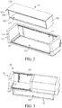
- the storage unit 10 includes a container body 11 that has a first inner cavity 111, and further includes a sub-storage body 12 that is mounted to the container body 11 in a manner of being movable between an extension position and a retraction position.
- the sub-storage body 12 has a second inner cavity 121.
- the second inner cavity 121 is formed by a cover 123 and a bottom board 122 that are arranged opposite to each other, and side walls 124 that are arranged opposite to each other.
- the bottom of the container body 11 is further provided with an opening 112.
- the sub-storage body 12 can move into or out of the container body 11 through the opening 112, so as the switch between the extension position and the retraction position.
- the sub-storage body 12 is completely located inside the first inner cavity 111 of the container body 11, and in this case, the sub-storage body 12 is at the retraction position. Then, the first inner cavity 111 of the sub-storage body 12 forms a first main storage portion of the storage unit 10, and objects can be stored in the first storage portion. A boundary of the first main storage portion is completely defined by a boundary of the sub-storage body 12. The cover 123 of the sub-storage body 12 forms a top wall of the first main storage portion.
- the sub-storage body may be partially located inside the first inner cavity of the container body.
- the first main storage portion is formed by the cover of the sub-storage body, partial side walls located in the first inner cavity, and cavity walls of the first inner cavity of the container body. That is, when the sub-storage body is partially located inside the first inner cavity of the container body, a part of the boundary of the first main storage portion is defined by the boundary of the sub-storage body.
- the sub-storage body 12 moves to the outside of the container body 11 through the opening 112 on the container body 11.
- the sub-storage body 12 is at the extension position, and the cover 123 of the sub-storage body 12 seals the opening 112 of the container body 11.
- cavity walls 113 of the first inner cavity 111 of the container body 11 and the cover 123 of the sub-storage body 12 form a second main storage portion of the storage unit 10.
- the second storage portion is located inside the container body 11.
- the second inner cavity 121 of the sub-storage body 12 forms an extended storage portion of the storage unit 10.
- the extended storage portion is located outside the container body 11. Objects can be stored in the second main storage portion and the extended storage portion, increasing the storage space of the storage unit 10.
- a boundary of the second main storage portion is defined by the cavity walls 113 of the first inner cavity 111 of the container body 11 and the cover 123 of the sub-storage body 12.
- the cover 123 of the sub-storage body 12 forms a bottom wall of the second main storage portion. Except the same cover 123, other parts of the boundaries of the first main storage portion and the second main storage portion are different.
- a volume of the first main storage portion of the storage unit 10 is the size of the second inner cavity 121 of the sub-storage body 12.
- the volume of the second main storage portion of the storage unit 10 is the size of the first inner cavity 111 of the container body 11.
- the volume of the first main storage portion is approximate to the volume of the second main storage portion.
- the size of the second inner cavity 121 of the sub-storage body 12 is smaller than the size of the first inner cavity 111 of the container body 11, and therefore, the volume of the second main storage portion is larger than the volume of the first main storage portion.
- the storage unit 10 of the present invention further includes locking portions 13 that are disposed on opposite cavity walls 113 of the first inner cavity 111.
- the two cavity walls 113 are provided opposite to each other along a direction perpendicular to a moving direction of the sub-storage body 12.
- the locking portion 13 includes: a sliding portion 131 elastically connected to the cavity wall 113 of the first inner cavity 111.
- the sliding portion 131 is elastically connected to the cavity wall 113 of the first inner cavity 111 by using an elastic member.
- the sliding portion 131 is provided with a support portion 132 that is away from the cavity wall 113 of the first inner cavity 111.
- the sliding portion 131 is capable of moving towards the sub-storage body 12 along a direction in which the cavity wall 113 of the first inner cavity 111 is opposite to the sub-storage body 12, so as to be in a locking state under the action of elasticity.
- the sub-storage body 12 is at the retraction position, and the bottom board 122 of the sub-storage body 12 is disposed on the support portions 132 of the sliding portions 131 that are arranged opposite to each other.
- the sub-storage body 12 is at the extension position, and a protruding portion 125, which extends towards the cavity walls 113 of the first inner cavity 111, of the cover 123 of the sub-storage body 12 is placed on the support portions 132 of the sliding portions 131.
- the sliding portion 131 can slide away from the sub-storage body 12 along the direction in which the cavity wall 113 of the first inner cavity 111 is opposite to the sub-storage body 1, so as to separate from the sub-storage body 12. Therefore, the sub-storage body 12 can move into or out of the opening 112 on the container body 11 freely, to realize switching between the retraction position and the extension position.
- support boards 114 are symmetrically disposed outside the first inner cavity 111 of the container body 11, and there is a gap 114a between the container body 11 and each support board 114.
- the elastic member is a spring 134
- a hole 115 that communicate the gap 114a and the first inner cavity 111 is provided on the container body 11.
- the number of holes is not limited. Two holes 115 are shown in FIG. 4 .
- the cavity wall 113 of the first inner cavity 111 is further provided with an insertion groove 118.
- the insertion groove 118 is arranged to surround the hole 115.
- a part, which facing the support board 114, of the sliding portion 131 is provided with a protrusion 133.
- the number of protrusions 133 is not limited. Two protrusions 133 are shown in the figure. Each protrusion 133 is inserted in the hole 115 and extends to the gap 114a.
- the protrusion 133 is provided with a slot. One end of the spring 134 is disposed in the slot, and the other end abuts against the board wall of the support board 114.
- the sliding portion 131 is capable of moving in the insertion groove 118 under the action of an external force.
- the shape of the sliding portion 131 is not limited, as long as the sliding portion 131 can move in the insertion groove 118.
- the cavity wall 113 of the first inner cavity 111 is provided with a notch 116 at a position close to the opening 112 of the container body 11.
- the sliding portion 131 is provided with a manipulation portion 135 at a part which is away from the first inner cavity 111.
- the manipulation portion 135 is located at the notch 116, and is used to be manipulated by a user so as to apply an acting force to the sliding portion 131. For example, when the sub-storage body 12 needs to switch from the retraction position to the extension position or switch from the extension position to the retraction position, the user applies an acting force to the sliding portion 131 by means of the manipulation portion 135.
- the spring 134 is compressed, the sliding portion 131 can move in the insertion groove 118 away from the sub-storage body 12 along the direction in which the cavity wall 113 of the first inner cavity 111 is opposite to the sub-storage body 12, so that the locking portion 13 is separated from the sub-storage body 12, achieving switching between the retraction position and the extension position.
- the sliding portion 131 When the manipulation portion 135 is released, no external force is applied to the sliding portion 131. Under the action of the elasticity of the spring 134, the sliding portion 131 can move in the insertion groove 118 towards the sub-storage body 12 along the direction in which the cavity wall 113 of the first inner cavity 111 is opposite to the sub-storage body 12, and the locking portion 13 is in a locking state, so as to support the sub-storage body 12.
- the protrusion can be provided on the support board.
- the protrusion is provided with a slot, one end of the spring is disposed in the slot, and the other end abuts against the sliding portion.
- the elastic member in the locking portion 13 is an elastic sheet 117.
- the elastic sheet 117 is located in the gap 114a between the container body 11 and the support board 114.
- the container body 11 is provided with a hole 115 that communicates the gap 114a and the first inner cavity 111 of the container body 11.
- the sliding portion 131 is provided with a protrusion 133 (referring to FIG. 5 ) at a portion facing the support board 114.
- the protrusion 133 is inserted in the hole 115 and extends to the gap 114a, and abuts against the elastic sheet 117.
- a user applies an acting force to the sliding portion 131 through the manipulation portion 135 provided at the notch 116.
- the protrusion abuts against the elastic sheet 117.
- the elastic sheet 117 is compressed.
- the sliding portion 131 can move in the insertion groove 118 away from the sub-storage body along the direction in which the cavity wall of the first inner cavity is opposite to the sub-storage body, so that the locking portion is separated from the sub-storage body, achieving switching between the retraction position and the extension position.
- the manipulation portion 135 is released, no external force is applied to the sliding portion 131.
- the sliding portion 131 can move in the insertion groove 118 towards the sub-storage body along the direction in which the cavity wall of the first inner cavity is opposite to the sub-storage body, and the locking portion 13 is in a locking state, so as to support the sub-storage body.
- a container body 21 of a storage unit 20 has a first inner cavity 212.
- a sub-storage body 22 of the storage unit 20 includes a bottom board 221 and a column 222 disposed on the bottom board 221.
- the number of columns 222 is not limited.
- Four columns 222 disposed at intervals are shown in the figure.
- the four columns 222 and the bottom board 221 form a second inner cavity 223 of the sub-storage body 22.
- the difference from the foregoing embodiments lies in that: the four columns 222 on the sub-storage body 22 are flexibly inserted inside cavity walls 211 of the first inner cavity 212 of the container body 21.
- the column 222 of the sub-storage body 22 is completely inserted in the cavity wall 211 of the first inner cavity 212, the bottom board 221 seals an opening of the container body 21, and the first inner cavity 212 of the container body 21 forms a first main storage portion.
- the column 222 at least partially extends out of the cavity wall 211 of the first inner cavity 212, and the cavity walls 211 of the first inner cavity 212 of the container body 21 and the cover 224 of the sub-storage body 22 form a second main storage portion.
- the first inner cavity 212 of the container body 21 forms the second main storage portion, that is, a volume of the first main storage portion is equal to a volume of the second main storage portion.
- a boundary of the first main storage portion is defined by the cavity walls of the first inner cavity 212 of the container body 21 and the bottom board 221 of the sub-storage body 22.
- a boundary of the second main storage portion is defined by the cavity walls of the first inner cavity 212 of the container body 21 and the cover 224 of the sub-storage body 22.
- the bottom of the container body 11 is provided with an opening 112, and the sub-storage body 11 can move into or out of the container body 11 through the opening 112, so as to switch between an extension position and a retraction position.
- an opening is provided on a side surface of a container body 31 of a storage unit 30, and a sub-storage body 32 can move into or out of the container body 31 through the side surface, so as to switch between the extension position and the retraction position.
- the sub-storage body 12 is capable of moving into or out of the container body 11 through the opening 112 on the container body 11, so as to switch between the retraction position and the extension position.
- a first clamping block 43 is disposed on a cavity wall 41 of a container body 40.
- the first clamping block 43 extends along a moving direction of a sub-storage body 50.
- the number of first clamping blocks 43 is not limited. Two first clamping blocks 43 disposed at an interval are shown in FIG. 11 .
- the sub-storage body 50 is provided with a second clamping block 60 at a part 51 which faces the cavity wall 41 provided with the first clamping block 43 of the container body 40.
- the second clamping block 60 extends along the moving direction of the sub-storage body 50.
- the number of second clamping blocks 60 is not limited.
- Two second clamping blocks 60 disposed at an interval are shown in FIG. 12 .
- the second clamping block 60 is clamped with the first clamping block 43, and the second clamping block 60 is movable with respect to the first clamping block 43 along the moving direction of the sub-storage body 50. Because the first clamping block 43 is stationary, stability of the sub-storage body 50 can be maintained during movement.
- the second clamping block 60 is clamped on the sub-storage body 50.
- the sub-storage body 50 is provided with a groove 52.
- the groove 52 includes body portions 522 that are disposed opposite to each other at an interval.
- Each body portion 522 is provided with a protrusion 521, and therefore is T-shaped as a whole.
- the protrusions 521 on the body portions 522 are also disposed opposite to each other at an interval.
- the second clamping block 60 includes a first groove 62 and a second groove 61 that are provided in a back-to-back manner.
- the first groove 62 extends along the moving direction of the sub-storage body 50, and is used for clamping with the first clamping block 43.
- the second groove 61 includes a first sub-groove 611 and a second sub-groove 612 that are provided in a back-to-back manner.
- the first sub-groove 611 and the second sub-groove 612 extend along the moving direction of the sub-storage body 50.
- the first sub-groove 611 and the second sub-groove 612 are separately used for clamping with each protrusion 521 on the groove 52 of the sub-storage body 50.
- the second clamping block 60 is clamped at the groove 52 on the sub-storage body 50.
- the sub-storage body 50 and the second clamping block 60 can be processed separately, facilitating molding.
- the second clamping block and the sub-storage body may be integrally formed.
- This embodiment provides a refrigerator, including a storage unit 10, 20, 30 according to any of the foregoing embodiments.
Landscapes
- Engineering & Computer Science (AREA)
- Chemical & Material Sciences (AREA)
- Combustion & Propulsion (AREA)
- Physics & Mathematics (AREA)
- Mechanical Engineering (AREA)
- Thermal Sciences (AREA)
- General Engineering & Computer Science (AREA)
- Devices That Are Associated With Refrigeration Equipment (AREA)
- Containers And Packaging Bodies Having A Special Means To Remove Contents (AREA)
- Vehicle Step Arrangements And Article Storage (AREA)
Claims (13)
- Aufbewahrungseinheit für einen Kühlschrank, die Folgendes umfasst: einen Behälterkörper (11, 21, 31, 40),
einen Aufbewahrungsteilkörper (12, 22, 32, 50), wobei der Aufbewahrungsteilkörper (12, 22, 32, 50) so an dem Behälterkörper (11, 21, 31, 40) angebracht ist, dass er sich zwischen einer ausgefahrenen Stellung und einer eingefahrenen Stellung bewegen lässt,
wobei sich der Aufbewahrungsteilkörper (12, 22, 32, 50) in der eingefahrenen Stellung zumindest teilweise in dem Behälterkörper (11, 21, 31, 40) befindet und die Aufbewahrungseinheit einen ersten Hauptaufbewahrungsabschnitt umfasst, der sich in dem Behälterkörper (11, 21, 31, 40) befindet, und
wobei sich der Aufbewahrungsteilkörper (12, 22, 32, 50) in der ausgefahrenen Stellung außerhalb des Behälterkörpers (11, 21, 31, 40) befindet und die Aufbewahrungseinheit einen zweiten Hauptaufbewahrungsabschnitt, der sich in dem Behälterkörper (11, 21, 31, 40) befindet, und einen ausgefahrenen Aufbewahrungsabschnitt umfasst, der sich außerhalb des Behälterkörpers (11, 21, 31, 40) befindet, wobei
der Behälterkörper (11, 21) eine an einer Seite ausgeschnittene Öffnung (112) umfasst und der Aufbewahrungsteilkörper (12, 22) in der Lage ist, sich über die Öffnung (112) in den Behälterkörper (11, 21) hinein oder aus diesem heraus zu bewegen, und dadurch gekennzeichnet, dass
der Aufbewahrungsteilkörper (12) eine Abdeckung (123) umfasst und die Abdeckung (123) in der ausgefahrenen Stellung die Öffnung (112) abdichtet, wobei die Abdeckung (123), wenn sich der Aufbewahrungsteilkörper (12) in der ausgefahrenen Stellung befindet, eine Bodenwand des zweiten Hauptaufbewahrungsabschnitts und, wenn sich der Aufbewahrungsteilkörper (12) in der eingefahrenen Stellung befindet, eine obere Wand des ersten Hauptaufbewahrungsabschnitts bildet. - Aufbewahrungseinheit nach Anspruch 1, dadurch gekennzeichnet, dass ein Volumen des zweiten Hauptaufbewahrungsabschnitts größer gleich einem Volumen des ersten Hauptaufbewahrungsabschnitts ist.
- Aufbewahrungseinheit nach einem der vorhergehenden Ansprüche, dadurch gekennzeichnet, dass ein Volumen des ersten Hauptaufbewahrungsabschnitts in etwa dem des zweiten Hauptaufbewahrungsabschnitts entspricht.
- Aufbewahrungseinheit nach einem der vorhergehenden Ansprüche, dadurch gekennzeichnet, dass sich Begrenzungen des ersten Hauptaufbewahrungsabschnitts und des zweiten Hauptaufbewahrungsabschnitts zumindest teilweise unterscheiden.
- Aufbewahrungseinheit nach einem der vorhergehenden Ansprüche, dadurch gekennzeichnet, dass zumindest ein Teil einer Begrenzung des ersten Hauptaufbewahrungsabschnitts durch den Aufbewahrungsteilkörper (12, 22, 32, 50) definiert ist.
- Aufbewahrungseinheit nach einem der vorhergehenden Ansprüche, dadurch gekennzeichnet, dass der Behälterkörper (11, 21) einen ersten Innenhohlraum (111, 212) und der Aufbewahrungsteilkörper (12, 22) einen zweiten Innenhohlraum (121, 223) aufweist und
der Aufbewahrungsteilkörper (12, 22), wenn er sich in der eingefahrenen Stellung befindet, sich zumindest teilweise in dem ersten Innenhohlraum (111, 212) befindet und zumindest einen Teil einer Begrenzung des ersten Hauptaufbewahrungsabschnitts bildet. - Aufbewahrungseinheit nach Anspruch 6, dadurch gekennzeichnet, dass der erste Hauptaufbewahrungsabschnitt, wenn sich der Aufbewahrungsteilkörper (12, 22) in der eingefahrenen Stellung befindet, von dem zweiten Innenhohlraum (121, 223) gebildet wird.
- Aufbewahrungseinheit nach einem der vorhergehenden Ansprüche, dadurch gekennzeichnet, dass der Behälterkörper (21) einen ersten Innenhohlraum (111, 212) aufweist und der Aufbewahrungsteilkörper (12, 22) eine untere Platte (122, 221) und eine an der unteren Platte (122, 221) angeordnete Strebe (222) umfasst,
die Strebe (222) in der eingefahrenen Stellung vollständig in eine Hohlraumwand (211) des ersten Innenhohlraums (212) eingeführt ist, die untere Platte (221) die Öffnung (112) abdichtet und der erste Innenhohlraum (212) den ersten Hauptaufbewahrungsabschnitt bildet und in der ausgefahrenen Stellung zumindest ein Teil der Strebe (222) aus der Hohlraumwand (211) des ersten Innenhohlraums (212) heraus verläuft und der erste Innenhohlraum (212) den zweiten Hauptaufbewahrungsabschnitt bildet. - Aufbewahrungseinheit nach einem der vorhergehenden Ansprüche, dadurch gekennzeichnet, dass sie ferner Arretierabschnitte (13) umfasst, wobei die Arretierabschnitte (13) den Aufbewahrungsteilkörper (12, 50) in der eingefahrenen und der ausgefahrenen Stellung arretieren, und die Arretierabschnitte (13), wenn der Aufbewahrungsteilkörper (12, 50) zwischen der ausgefahrenen und der eingefahrenen Stellung wechselt, von dem Aufbewahrungsteilkörper (12, 50) getrennt werden.
- Aufbewahrungseinheit nach einem der vorhergehenden Ansprüche 6 bis 9, dadurch gekennzeichnet, dass der Behälterkörper (11) den ersten Innenhohlraum (111) aufweist und die Arretierabschnitte (13) an gegenüberliegenden Hohlraumwänden (113) des ersten Innenhohlraums (111) angeordnet sind.
- Aufbewahrungseinheit nach Anspruch 10, dadurch gekennzeichnet, dass der Arretierabschnitt (13) einen Gleitabschnitt (131) umfasst, der federnd mit der Hohlraumwand (113) verbunden ist, der Gleitabschnitt (131) in der Lage ist, in einer Richtung, in der die Hohlraumwand (113) dem Aufbewahrungsteilkörper (12, 50) gegenüberliegt, zu dem Aufbewahrungsteilkörper (12, 50) hin zu gleiten und den Aufbewahrungsteilkörper (12, 50) unter Einwirkung einer Federkraft zu arretieren oder von dem Aufbewahrungsteilkörper (12, 50) weg zu gleiten und sich so davon zu trennen.
- Aufbewahrungseinheit nach Anspruch 11, dadurch gekennzeichnet, dass der Aufbewahrungsteilkörper (12, 50) in einer Bewegungsrichtung desselben einen vorstehenden Abschnitt (125) und eine untere Platte (122) umfasst, die einander gegenüberliegend angeordnet sind, die untere Platte (122) in der eingefahrenen Stellung an den Gleitabschnitten (131) angeordnet ist und in der ausgefahrenen Stellung der vorstehende Abschnitt (125) an dem Gleitabschnitt (131) platziert ist.
- Kühlschrank, dadurch gekennzeichnet, dass er die Aufbewahrungseinheit nach einem der vorhergehenden Ansprüche umfasst.
Priority Applications (1)
| Application Number | Priority Date | Filing Date | Title |
|---|---|---|---|
| PL18177746T PL3418659T3 (pl) | 2017-06-23 | 2018-06-14 | Jednostki przechowywania i lodówki |
Applications Claiming Priority (1)
| Application Number | Priority Date | Filing Date | Title |
|---|---|---|---|
| CN201710485729.6A CN109114874B (zh) | 2017-06-23 | 2017-06-23 | 储藏单元及冰箱 |
Publications (2)
| Publication Number | Publication Date |
|---|---|
| EP3418659A1 EP3418659A1 (de) | 2018-12-26 |
| EP3418659B1 true EP3418659B1 (de) | 2021-04-07 |
Family
ID=62636096
Family Applications (1)
| Application Number | Title | Priority Date | Filing Date |
|---|---|---|---|
| EP18177746.7A Active EP3418659B1 (de) | 2017-06-23 | 2018-06-14 | Lagereinheiten und kühlschränke |
Country Status (3)
| Country | Link |
|---|---|
| EP (1) | EP3418659B1 (de) |
| CN (1) | CN109114874B (de) |
| PL (1) | PL3418659T3 (de) |
Families Citing this family (1)
| Publication number | Priority date | Publication date | Assignee | Title |
|---|---|---|---|---|
| CN113074477B (zh) * | 2020-01-03 | 2023-09-15 | 博西华电器(江苏)有限公司 | 冰箱 |
Citations (1)
| Publication number | Priority date | Publication date | Assignee | Title |
|---|---|---|---|---|
| WO2016023091A1 (en) * | 2014-08-14 | 2016-02-18 | Electrolux Do Brasil S.A. | Telescoping fixture applied to a refrigerator door or the like |
Family Cites Families (20)
| Publication number | Priority date | Publication date | Assignee | Title |
|---|---|---|---|---|
| KR0150602B1 (ko) * | 1995-11-02 | 1998-11-02 | 김광호 | 냉장고 도어의 확장형 보조 수납함 |
| CN2691339Y (zh) * | 2004-04-11 | 2005-04-13 | 杨书堂 | 容积可调旅行箱 |
| US7651182B2 (en) * | 2006-03-31 | 2010-01-26 | Maytag Corporation | Adjustable retainer assembly for a refrigerator door storage unit |
| KR20070102188A (ko) * | 2006-04-14 | 2007-10-18 | 주식회사 대우일렉트로닉스 | 냉장고 도어선반 |
| CN201484512U (zh) * | 2009-06-30 | 2010-05-26 | 杨枫 | 医检箱体的动力传递装置 |
| CN201555417U (zh) * | 2009-10-12 | 2010-08-18 | 沈凯峰 | 一种设有拦架的可伸缩式冰箱冷藏瓶座 |
| CN202060189U (zh) * | 2011-05-19 | 2011-12-07 | 山东科技大学 | 折叠式饭盒 |
| US9429355B2 (en) * | 2011-11-15 | 2016-08-30 | Lg Electronics Inc. | Refrigerator |
| CN202371967U (zh) * | 2011-12-12 | 2012-08-08 | 苏州三星电子有限公司 | 瓶架 |
| CN202436341U (zh) * | 2012-02-14 | 2012-09-19 | 崔雷 | 一种可扩容的箱包 |
| CN203050152U (zh) * | 2012-09-19 | 2013-07-10 | 烟台新科钢结构有限公司 | 一种可移动的套插式扩容集装箱房屋 |
| CN202959456U (zh) * | 2012-12-06 | 2013-06-05 | 攀枝花市第三十八中小学校 | 伸缩衣柜 |
| KR102028022B1 (ko) * | 2013-04-05 | 2019-10-04 | 삼성전자주식회사 | 냉장고 |
| US9513047B2 (en) * | 2014-01-10 | 2016-12-06 | Haier Us Appliance Solutions, Inc. | Door module assembly for a refrigerator appliance |
| CN104287424B (zh) * | 2014-10-09 | 2016-08-17 | 平湖市四通箱包有限公司 | 一种减负式书包 |
| CN204648816U (zh) * | 2015-04-21 | 2015-09-16 | 苏州三星电子有限公司 | 冰箱抽屉和冰箱 |
| CN105953516B (zh) * | 2016-05-16 | 2019-03-29 | 海信容声(广东)冰箱有限公司 | 一种冰箱门搁架结构及冰箱 |
| CN206025486U (zh) * | 2016-08-29 | 2017-03-22 | 田先农 | 行李箱 |
| TR201617591A2 (tr) * | 2016-12-01 | 2018-06-21 | Arcelik As | Kapi rafi separatörü i̇çeren bi̇r buzdolabi |
| CN106524660B (zh) * | 2016-12-16 | 2019-07-02 | 青岛海尔股份有限公司 | 冰箱及其搁物装置 |
-
2017
- 2017-06-23 CN CN201710485729.6A patent/CN109114874B/zh active Active
-
2018
- 2018-06-14 PL PL18177746T patent/PL3418659T3/pl unknown
- 2018-06-14 EP EP18177746.7A patent/EP3418659B1/de active Active
Patent Citations (1)
| Publication number | Priority date | Publication date | Assignee | Title |
|---|---|---|---|---|
| WO2016023091A1 (en) * | 2014-08-14 | 2016-02-18 | Electrolux Do Brasil S.A. | Telescoping fixture applied to a refrigerator door or the like |
Also Published As
| Publication number | Publication date |
|---|---|
| PL3418659T3 (pl) | 2021-10-25 |
| CN109114874B (zh) | 2021-12-07 |
| EP3418659A1 (de) | 2018-12-26 |
| CN109114874A (zh) | 2019-01-01 |
Similar Documents
| Publication | Publication Date | Title |
|---|---|---|
| AU2012323804B2 (en) | Device for storing utensils, especially tools | |
| US8960826B2 (en) | Refrigerator | |
| US11070038B2 (en) | Cabinet system | |
| US8840205B2 (en) | Refrigerator appliance and a shelf assembly for the same | |
| KR20160101594A (ko) | 가변선반장치 및 이를 포함한 냉장고 | |
| KR20110002589A (ko) | 가변선반 및 이를 갖춘 냉장고 | |
| JP2009011396A (ja) | キッチン収納庫 | |
| CN109813039A (zh) | 储物装置及具有该储物装置的冰箱 | |
| CA2903047A1 (en) | Under cupboard hideaway cabinet | |
| EP3418659B1 (de) | Lagereinheiten und kühlschränke | |
| KR101774101B1 (ko) | 냉장고 선반 | |
| KR100881989B1 (ko) | 냉장고용 선반구조 | |
| CN105605853A (zh) | 冰箱 | |
| KR101585495B1 (ko) | 고정식 서랍이 구비된 붙박이장 | |
| KR102181001B1 (ko) | 주방용 선반 | |
| KR100471105B1 (ko) | 냉장고 | |
| WO2008080943A1 (en) | A refrigerator | |
| KR200337573Y1 (ko) | 가변형 서랍 구획판 | |
| JP4400930B2 (ja) | カウンター構造 | |
| CN222733149U (zh) | 抽屉及制冷装置 | |
| JP5052184B2 (ja) | キッチン収納庫 | |
| KR20050119852A (ko) | 냉장고 | |
| KR101053993B1 (ko) | 다용도 캐비넷 | |
| KR102125657B1 (ko) | 신축형 수납함 | |
| CN111059854B (zh) | 可分割内部空间大小的抽屉及具有该抽屉的冰箱 |
Legal Events
| Date | Code | Title | Description |
|---|---|---|---|
| PUAI | Public reference made under article 153(3) epc to a published international application that has entered the european phase |
Free format text: ORIGINAL CODE: 0009012 |
|
| STAA | Information on the status of an ep patent application or granted ep patent |
Free format text: STATUS: THE APPLICATION HAS BEEN PUBLISHED |
|
| AK | Designated contracting states |
Kind code of ref document: A1 Designated state(s): AL AT BE BG CH CY CZ DE DK EE ES FI FR GB GR HR HU IE IS IT LI LT LU LV MC MK MT NL NO PL PT RO RS SE SI SK SM TR |
|
| AX | Request for extension of the european patent |
Extension state: BA ME |
|
| STAA | Information on the status of an ep patent application or granted ep patent |
Free format text: STATUS: REQUEST FOR EXAMINATION WAS MADE |
|
| 17P | Request for examination filed |
Effective date: 20190626 |
|
| RBV | Designated contracting states (corrected) |
Designated state(s): AL AT BE BG CH CY CZ DE DK EE ES FI FR GB GR HR HU IE IS IT LI LT LU LV MC MK MT NL NO PL PT RO RS SE SI SK SM TR |
|
| STAA | Information on the status of an ep patent application or granted ep patent |
Free format text: STATUS: EXAMINATION IS IN PROGRESS |
|
| 17Q | First examination report despatched |
Effective date: 20191021 |
|
| GRAP | Despatch of communication of intention to grant a patent |
Free format text: ORIGINAL CODE: EPIDOSNIGR1 |
|
| STAA | Information on the status of an ep patent application or granted ep patent |
Free format text: STATUS: GRANT OF PATENT IS INTENDED |
|
| INTG | Intention to grant announced |
Effective date: 20201123 |
|
| GRAS | Grant fee paid |
Free format text: ORIGINAL CODE: EPIDOSNIGR3 |
|
| GRAA | (expected) grant |
Free format text: ORIGINAL CODE: 0009210 |
|
| STAA | Information on the status of an ep patent application or granted ep patent |
Free format text: STATUS: THE PATENT HAS BEEN GRANTED |
|
| AK | Designated contracting states |
Kind code of ref document: B1 Designated state(s): AL AT BE BG CH CY CZ DE DK EE ES FI FR GB GR HR HU IE IS IT LI LT LU LV MC MK MT NL NO PL PT RO RS SE SI SK SM TR |
|
| REG | Reference to a national code |
Ref country code: GB Ref legal event code: FG4D |
|
| REG | Reference to a national code |
Ref country code: AT Ref legal event code: REF Ref document number: 1380213 Country of ref document: AT Kind code of ref document: T Effective date: 20210415 Ref country code: CH Ref legal event code: EP |
|
| REG | Reference to a national code |
Ref country code: DE Ref legal event code: R096 Ref document number: 602018015013 Country of ref document: DE |
|
| REG | Reference to a national code |
Ref country code: IE Ref legal event code: FG4D |
|
| REG | Reference to a national code |
Ref country code: LT Ref legal event code: MG9D |
|
| REG | Reference to a national code |
Ref country code: NL Ref legal event code: MP Effective date: 20210407 Ref country code: AT Ref legal event code: MK05 Ref document number: 1380213 Country of ref document: AT Kind code of ref document: T Effective date: 20210407 |
|
| PG25 | Lapsed in a contracting state [announced via postgrant information from national office to epo] |
Ref country code: FI Free format text: LAPSE BECAUSE OF FAILURE TO SUBMIT A TRANSLATION OF THE DESCRIPTION OR TO PAY THE FEE WITHIN THE PRESCRIBED TIME-LIMIT Effective date: 20210407 Ref country code: HR Free format text: LAPSE BECAUSE OF FAILURE TO SUBMIT A TRANSLATION OF THE DESCRIPTION OR TO PAY THE FEE WITHIN THE PRESCRIBED TIME-LIMIT Effective date: 20210407 Ref country code: LT Free format text: LAPSE BECAUSE OF FAILURE TO SUBMIT A TRANSLATION OF THE DESCRIPTION OR TO PAY THE FEE WITHIN THE PRESCRIBED TIME-LIMIT Effective date: 20210407 Ref country code: AT Free format text: LAPSE BECAUSE OF FAILURE TO SUBMIT A TRANSLATION OF THE DESCRIPTION OR TO PAY THE FEE WITHIN THE PRESCRIBED TIME-LIMIT Effective date: 20210407 Ref country code: BG Free format text: LAPSE BECAUSE OF FAILURE TO SUBMIT A TRANSLATION OF THE DESCRIPTION OR TO PAY THE FEE WITHIN THE PRESCRIBED TIME-LIMIT Effective date: 20210707 Ref country code: NL Free format text: LAPSE BECAUSE OF FAILURE TO SUBMIT A TRANSLATION OF THE DESCRIPTION OR TO PAY THE FEE WITHIN THE PRESCRIBED TIME-LIMIT Effective date: 20210407 |
|
| PG25 | Lapsed in a contracting state [announced via postgrant information from national office to epo] |
Ref country code: RS Free format text: LAPSE BECAUSE OF FAILURE TO SUBMIT A TRANSLATION OF THE DESCRIPTION OR TO PAY THE FEE WITHIN THE PRESCRIBED TIME-LIMIT Effective date: 20210407 Ref country code: SE Free format text: LAPSE BECAUSE OF FAILURE TO SUBMIT A TRANSLATION OF THE DESCRIPTION OR TO PAY THE FEE WITHIN THE PRESCRIBED TIME-LIMIT Effective date: 20210407 Ref country code: NO Free format text: LAPSE BECAUSE OF FAILURE TO SUBMIT A TRANSLATION OF THE DESCRIPTION OR TO PAY THE FEE WITHIN THE PRESCRIBED TIME-LIMIT Effective date: 20210707 Ref country code: LV Free format text: LAPSE BECAUSE OF FAILURE TO SUBMIT A TRANSLATION OF THE DESCRIPTION OR TO PAY THE FEE WITHIN THE PRESCRIBED TIME-LIMIT Effective date: 20210407 Ref country code: PT Free format text: LAPSE BECAUSE OF FAILURE TO SUBMIT A TRANSLATION OF THE DESCRIPTION OR TO PAY THE FEE WITHIN THE PRESCRIBED TIME-LIMIT Effective date: 20210809 Ref country code: GR Free format text: LAPSE BECAUSE OF FAILURE TO SUBMIT A TRANSLATION OF THE DESCRIPTION OR TO PAY THE FEE WITHIN THE PRESCRIBED TIME-LIMIT Effective date: 20210708 Ref country code: IS Free format text: LAPSE BECAUSE OF FAILURE TO SUBMIT A TRANSLATION OF THE DESCRIPTION OR TO PAY THE FEE WITHIN THE PRESCRIBED TIME-LIMIT Effective date: 20210807 |
|
| REG | Reference to a national code |
Ref country code: DE Ref legal event code: R097 Ref document number: 602018015013 Country of ref document: DE |
|
| PG25 | Lapsed in a contracting state [announced via postgrant information from national office to epo] |
Ref country code: SK Free format text: LAPSE BECAUSE OF FAILURE TO SUBMIT A TRANSLATION OF THE DESCRIPTION OR TO PAY THE FEE WITHIN THE PRESCRIBED TIME-LIMIT Effective date: 20210407 Ref country code: SM Free format text: LAPSE BECAUSE OF FAILURE TO SUBMIT A TRANSLATION OF THE DESCRIPTION OR TO PAY THE FEE WITHIN THE PRESCRIBED TIME-LIMIT Effective date: 20210407 Ref country code: EE Free format text: LAPSE BECAUSE OF FAILURE TO SUBMIT A TRANSLATION OF THE DESCRIPTION OR TO PAY THE FEE WITHIN THE PRESCRIBED TIME-LIMIT Effective date: 20210407 Ref country code: ES Free format text: LAPSE BECAUSE OF FAILURE TO SUBMIT A TRANSLATION OF THE DESCRIPTION OR TO PAY THE FEE WITHIN THE PRESCRIBED TIME-LIMIT Effective date: 20210407 Ref country code: RO Free format text: LAPSE BECAUSE OF FAILURE TO SUBMIT A TRANSLATION OF THE DESCRIPTION OR TO PAY THE FEE WITHIN THE PRESCRIBED TIME-LIMIT Effective date: 20210407 Ref country code: DK Free format text: LAPSE BECAUSE OF FAILURE TO SUBMIT A TRANSLATION OF THE DESCRIPTION OR TO PAY THE FEE WITHIN THE PRESCRIBED TIME-LIMIT Effective date: 20210407 Ref country code: CZ Free format text: LAPSE BECAUSE OF FAILURE TO SUBMIT A TRANSLATION OF THE DESCRIPTION OR TO PAY THE FEE WITHIN THE PRESCRIBED TIME-LIMIT Effective date: 20210407 Ref country code: MC Free format text: LAPSE BECAUSE OF FAILURE TO SUBMIT A TRANSLATION OF THE DESCRIPTION OR TO PAY THE FEE WITHIN THE PRESCRIBED TIME-LIMIT Effective date: 20210407 |
|
| REG | Reference to a national code |
Ref country code: CH Ref legal event code: PL |
|
| PLBE | No opposition filed within time limit |
Free format text: ORIGINAL CODE: 0009261 |
|
| STAA | Information on the status of an ep patent application or granted ep patent |
Free format text: STATUS: NO OPPOSITION FILED WITHIN TIME LIMIT |
|
| REG | Reference to a national code |
Ref country code: BE Ref legal event code: MM Effective date: 20210630 |
|
| 26N | No opposition filed |
Effective date: 20220110 |
|
| PG25 | Lapsed in a contracting state [announced via postgrant information from national office to epo] |
Ref country code: LU Free format text: LAPSE BECAUSE OF NON-PAYMENT OF DUE FEES Effective date: 20210614 |
|
| PG25 | Lapsed in a contracting state [announced via postgrant information from national office to epo] |
Ref country code: LI Free format text: LAPSE BECAUSE OF NON-PAYMENT OF DUE FEES Effective date: 20210630 Ref country code: IE Free format text: LAPSE BECAUSE OF NON-PAYMENT OF DUE FEES Effective date: 20210614 Ref country code: CH Free format text: LAPSE BECAUSE OF NON-PAYMENT OF DUE FEES Effective date: 20210630 |
|
| PG25 | Lapsed in a contracting state [announced via postgrant information from national office to epo] |
Ref country code: IS Free format text: LAPSE BECAUSE OF FAILURE TO SUBMIT A TRANSLATION OF THE DESCRIPTION OR TO PAY THE FEE WITHIN THE PRESCRIBED TIME-LIMIT Effective date: 20210807 Ref country code: FR Free format text: LAPSE BECAUSE OF NON-PAYMENT OF DUE FEES Effective date: 20210630 Ref country code: AL Free format text: LAPSE BECAUSE OF FAILURE TO SUBMIT A TRANSLATION OF THE DESCRIPTION OR TO PAY THE FEE WITHIN THE PRESCRIBED TIME-LIMIT Effective date: 20210407 |
|
| PG25 | Lapsed in a contracting state [announced via postgrant information from national office to epo] |
Ref country code: BE Free format text: LAPSE BECAUSE OF NON-PAYMENT OF DUE FEES Effective date: 20210630 |
|
| PGFP | Annual fee paid to national office [announced via postgrant information from national office to epo] |
Ref country code: IT Payment date: 20220630 Year of fee payment: 5 |
|
| GBPC | Gb: european patent ceased through non-payment of renewal fee |
Effective date: 20220614 |
|
| PG25 | Lapsed in a contracting state [announced via postgrant information from national office to epo] |
Ref country code: GB Free format text: LAPSE BECAUSE OF NON-PAYMENT OF DUE FEES Effective date: 20220614 |
|
| PG25 | Lapsed in a contracting state [announced via postgrant information from national office to epo] |
Ref country code: CY Free format text: LAPSE BECAUSE OF FAILURE TO SUBMIT A TRANSLATION OF THE DESCRIPTION OR TO PAY THE FEE WITHIN THE PRESCRIBED TIME-LIMIT Effective date: 20210407 |
|
| PG25 | Lapsed in a contracting state [announced via postgrant information from national office to epo] |
Ref country code: HU Free format text: LAPSE BECAUSE OF FAILURE TO SUBMIT A TRANSLATION OF THE DESCRIPTION OR TO PAY THE FEE WITHIN THE PRESCRIBED TIME-LIMIT; INVALID AB INITIO Effective date: 20180614 |
|
| PG25 | Lapsed in a contracting state [announced via postgrant information from national office to epo] |
Ref country code: MK Free format text: LAPSE BECAUSE OF FAILURE TO SUBMIT A TRANSLATION OF THE DESCRIPTION OR TO PAY THE FEE WITHIN THE PRESCRIBED TIME-LIMIT Effective date: 20210407 |
|
| PG25 | Lapsed in a contracting state [announced via postgrant information from national office to epo] |
Ref country code: IT Free format text: LAPSE BECAUSE OF NON-PAYMENT OF DUE FEES Effective date: 20230614 |
|
| PG25 | Lapsed in a contracting state [announced via postgrant information from national office to epo] |
Ref country code: MT Free format text: LAPSE BECAUSE OF FAILURE TO SUBMIT A TRANSLATION OF THE DESCRIPTION OR TO PAY THE FEE WITHIN THE PRESCRIBED TIME-LIMIT Effective date: 20210407 |
|
| PGFP | Annual fee paid to national office [announced via postgrant information from national office to epo] |
Ref country code: PL Payment date: 20250604 Year of fee payment: 8 Ref country code: DE Payment date: 20250630 Year of fee payment: 8 |
|
| PGFP | Annual fee paid to national office [announced via postgrant information from national office to epo] |
Ref country code: TR Payment date: 20250611 Year of fee payment: 8 |