EP3418681B1 - Étalonnage d'un capteur de triangulation - Google Patents
Étalonnage d'un capteur de triangulation Download PDFInfo
- Publication number
- EP3418681B1 EP3418681B1 EP17177439.1A EP17177439A EP3418681B1 EP 3418681 B1 EP3418681 B1 EP 3418681B1 EP 17177439 A EP17177439 A EP 17177439A EP 3418681 B1 EP3418681 B1 EP 3418681B1
- Authority
- EP
- European Patent Office
- Prior art keywords
- calibration
- light
- target
- light pattern
- calibration target
- Prior art date
- Legal status (The legal status is an assumption and is not a legal conclusion. Google has not performed a legal analysis and makes no representation as to the accuracy of the status listed.)
- Active
Links
Images



Classifications
-
- G—PHYSICS
- G01—MEASURING; TESTING
- G01B—MEASURING LENGTH, THICKNESS OR SIMILAR LINEAR DIMENSIONS; MEASURING ANGLES; MEASURING AREAS; MEASURING IRREGULARITIES OF SURFACES OR CONTOURS
- G01B11/00—Measuring arrangements characterised by the use of optical techniques
- G01B11/002—Measuring arrangements characterised by the use of optical techniques for measuring two or more coordinates
- G01B11/005—Measuring arrangements characterised by the use of optical techniques for measuring two or more coordinates coordinate measuring machines
-
- G—PHYSICS
- G01—MEASURING; TESTING
- G01B—MEASURING LENGTH, THICKNESS OR SIMILAR LINEAR DIMENSIONS; MEASURING ANGLES; MEASURING AREAS; MEASURING IRREGULARITIES OF SURFACES OR CONTOURS
- G01B11/00—Measuring arrangements characterised by the use of optical techniques
- G01B11/24—Measuring arrangements characterised by the use of optical techniques for measuring contours or curvatures
- G01B11/25—Measuring arrangements characterised by the use of optical techniques for measuring contours or curvatures by projecting a pattern, e.g. one or more lines, moiré fringes on the object
- G01B11/2518—Projection by scanning of the object
-
- G—PHYSICS
- G01—MEASURING; TESTING
- G01B—MEASURING LENGTH, THICKNESS OR SIMILAR LINEAR DIMENSIONS; MEASURING ANGLES; MEASURING AREAS; MEASURING IRREGULARITIES OF SURFACES OR CONTOURS
- G01B5/00—Measuring arrangements characterised by the use of mechanical techniques
- G01B5/0011—Arrangements for eliminating or compensation of measuring errors due to temperature or weight
- G01B5/0014—Arrangements for eliminating or compensation of measuring errors due to temperature or weight due to temperature
-
- G—PHYSICS
- G01—MEASURING; TESTING
- G01B—MEASURING LENGTH, THICKNESS OR SIMILAR LINEAR DIMENSIONS; MEASURING ANGLES; MEASURING AREAS; MEASURING IRREGULARITIES OF SURFACES OR CONTOURS
- G01B11/00—Measuring arrangements characterised by the use of optical techniques
- G01B11/24—Measuring arrangements characterised by the use of optical techniques for measuring contours or curvatures
- G01B11/25—Measuring arrangements characterised by the use of optical techniques for measuring contours or curvatures by projecting a pattern, e.g. one or more lines, moiré fringes on the object
- G01B11/2504—Calibration devices
-
- G—PHYSICS
- G01—MEASURING; TESTING
- G01B—MEASURING LENGTH, THICKNESS OR SIMILAR LINEAR DIMENSIONS; MEASURING ANGLES; MEASURING AREAS; MEASURING IRREGULARITIES OF SURFACES OR CONTOURS
- G01B21/00—Measuring arrangements or details thereof, where the measuring technique is not covered by the other groups of this subclass, unspecified or not relevant
- G01B21/02—Measuring arrangements or details thereof, where the measuring technique is not covered by the other groups of this subclass, unspecified or not relevant for measuring length, width, or thickness
- G01B21/04—Measuring arrangements or details thereof, where the measuring technique is not covered by the other groups of this subclass, unspecified or not relevant for measuring length, width, or thickness by measuring coordinates of points
- G01B21/042—Calibration or calibration artifacts
Definitions
- the present invention generally pertains to respective methods for calibration of a triangulation sensor and for compensation of measurements based on the calibration.
- a line generated by a laser unit e.g. by moving a laser point along such line or by providing a laser fan, is generated on an object to be measured and the light reflected from the surface is detected by a camera consisting of a light sensitive image sensor (light detector) and electronics to control the image sensor and read out the image. An image of the reflected light is captured and distance information according to the contour of the detected line is derived. Based thereon, topography of the object's surface can be determined.
- WO 2007/125081 A1 discloses a further approach for actively controlling the power of illuminating light in dependency upon an intensity detected by a camera.
- the light emitting unit can be arranged with known position and orientation relative to the light receiving unit and the triangulation sensor being adapted to provide triangulation-based position measurements, in particular with reference to an outer coordinate system by determining image positions of reflected measuring light in an inner sensor image coordinate system.
- the triangulation sensor and the calibration target are provided inside a climate volume in defined relative position with reference to an outer coordinate system.
- the climate volume can be a climatic chamber or similar.
- the properties of the enclosed volume, like temperature or humidity, can be set and varied in defined manner.
- the volume can be chosen to enclose a calibration setup which may comprise a CMM or the like.
- the measuring light of the triangulation sensor is directed towards the calibration target so that it impinges on the calibration target. Furthermore, a defined variation of a temperature in the climate volume is applied and a set of calibration temperatures is defined thereby. By that a defined calibration of the triangulation sensor over temperature becomes possible.
- the set of captured images is processed by deriving a respective set of light pattern appearances with reference to the inner sensor image coordinate system, the light pattern appearances provide information about courses and/or positions of the light pattern projected onto the calibration target in the captured image.
- Calibration data is derived based on the relative position of the triangulation sensor and the calibration target, the set of calibration temperatures and the set of light pattern appearances.
- the measuring light is emitted so that a laser line is defined, wherein a reference orientation of the laser line can be adjusted to be parallel or perpendicular to a lateral measuring X-axis, in particular wherein the measuring light is designed as a laser line and a laser plane is defined by emitting of the measuring light.
- An advantage of providing the measuring light in form of one or more lines, in particular of a laser line, is that a comparatively large amount of distance data can be generated by acquiring one image of the projected line and deriving or calculating respective distances along the captured line based on a position and/or orientation of the line as captured in the image.
- the lines can preferably intersect or being oriented inclined relative to each other.
- a triangulation sensor can typically be equipped with a light source which generates a light line or more particularly with a laser source which is designed to provide a laser line. Position and/or distance measurements to measuring points at an object can be provided along the entire line (simultaneously) by capturing and processing an image of the projected line.
- the calibration feature is embodied as a calibration pattern and the processing of the set of captured images comprises deriving a set of pattern image positions with reference to the inner sensor image coordinate system, the pattern image positions provide information about a position of the calibration pattern in the captured images.
- the calibration feature can be realised according to a pattern mentioned above or shown below.
- the calibration pattern can be printed onto the calibration target and be illuminated with an additional illumination light source.
- the calibration feature is provided by a structural design of the calibration target, wherein the calibration target defines at least one edge.
- the measuring light is directed towards the calibration target so that the light pattern covers the edge and deriving the set of light pattern appearances comprises determining the courses of the projected light patterns covering the edge.
- the calibration target is provided by a specifically designed artefact, which allows e.g. determination of a height of the projected measuring light (position in Z-direction) and a tilt of the projection by processing the shape of the projection on the target.
- the calibration target is aligned and designed so that the calibration feature provides a planar surface facing the triangulation sensor, in particular wherein a normal on the planar surface is parallel to an optical axis of the light emitting unit, the planar surface provides a varying width in a first direction (X- or I-direction, wherein X refers to the outer and I refers to the inner coordinate system) with respect to a second direction (Z or J), in particular provides a triangular shape, and the determinations of the set of light pattern appearances comprise determining the extensions of the light pattern on the planar surface in the first direction (X) based on the known width of the surface and deriving a position of the light pattern in the second direction (Z) based on the determined width.
- the calibration target may be aligned and designed so that the calibration feature provides at least one sloped surface relative to the triangulation sensor, i.e. the surface comprises a defined inclination relative to the sensor or relative to a plane which is perpendicular to the measuring axis.
- the determinations of the set of light pattern appearances comprise determining an orientation of the light patterns on the sloped surface and deriving tilt information for the measuring light based on at least the determined orientations of the light pattern.
- an offset of the emitted measuring light relative to a (reference) emission axis can be determined based on one of the light pattern appearances.
- a plurality of calibration targets is provided each of which having a calibration feature, wherein image data relating to the plurality of calibration targets is acquired and processed with respect to light pattern appearances and/or pattern image positions.
- the plurality of targets provides for calibration with both higher precision and more degrees of freedom.
- a set of camera calibration parameters can be determined by determining positions of a reference feature in the set of images according to the set of calibration temperatures, wherein the reference feature is provided with known shape and dimension in a defined position in the outer coordinate system. This allows for calibration of the light receiving system.
- a set of feature image positions can be derived based on the set of captured images by determining positions for the calibration feature in the set of images and the calibration data may be derived by interpolating the positions. This enables to provide respective calibrations over a defined temperature range.
- a calibration function can be derived based on the calibration data, wherein the calibration function provides compensation data with respect to an orientation of the light emitting unit relative to the light receiving unit, and a distance and/or orientation between the triangulation sensor and the calibration target as a function of temperature.
- Such function may provide a continuous representation of a distance error in dependency of temperature data. It may be realized as a look-up table.
- the relative position and orientation of the target and the sensor preferably remain unchanged during a temperature calibration measurement.
- Knowledge about a reference distance between the triangulation sensor and the calibration artefact e.g. the distance measured at normal measuring conditions to at least one particular point at the artefact
- Measured positions, in particular Y-coordinates of the positions can be put in relation to the reference distance and particular deviations from the reference distance can be derived for the respective coordinates.
- the calibration data can comprise a look-up table or matrix which provides a set of compensation distance values, wherein a particular compensation distance value is identifiable based on a selection of a defined temperature and correspondingly assigned coordinates.
- a related compensation value can be derived based on the information comprised in the look-up table or matrix.
- the look-up table may have finite grid spacing and values between the grid nodes are interpolated to provide a continuous compensation function.
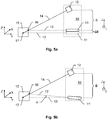
- FIG. 5a shows a change of the baseline B of a triangulation sensor 10'.
- the sensor 10' comprises a light emitting unit 11, here a laser, and a camera 12 for detecting reflected light at an object 15 to be measured.
- a laser line 13 is emittable by the laser source 11. The laser in its original position is shown with reference sign 11.
- Figure 5b shows a constant baseline B but a rotation of the emission axis around the I-axis due to e.g. thermal influences.
- a deviation in the orientation of the emitted laser line from an original direction 13 to a deviated direction 13' can occur.
- the emission direction is shifted by an angle ⁇ .
- the laser generates an illuminated pattern at a true position 16.
- the system would assume that the illuminated region can only be provided by an intersection of the originally emitted laser 13 and a direction 14 according to which the projection is captured.
- An assumed measuring point 17 would be derived based on that. However, the correct measuring point would be the illuminated one 16. Again, there occurs an error in determination of coordinates of the measuring point if no compensation is applied.
- the disclosure presents an improved type of calibration target for thermal calibration which allows full tracking of the pose of the line laser as well as the camera pose, both relative to the mechanical reference frame.
- the scanner can remain accurate over a larger temperature range without re-qualification.
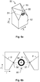
- the target 50 this is designed to allow separation of baseline shift from laser pitch variation.
- the target has a flat middle surface 52 and two sloped side surfaces 51,53.
- the calibration setup is provided so that the triangulation sensor is mounted relative to the target 50 so that the laser line 55 hits the middle surface 52 e.g. perpendicularly.
- the length of the laser line 55 (along X-axis) on the central part 52 depends on the height of the laser line (position along Z-axis).
- the middle surface 52 is slightly tilted relative to an optical axis of the light emitting unit of the sensor.
- a transformation of coordinates between the inner coordinate system (I,J) and the outer coordinate system (X,Y,Z) is provided.
- a transformation scale can be calculated as well.
- the scale can be derived between the pixel coordinate system (inner coordinate system; I,J) and the outer system (X,Y,Z) so that a real-world distance between the ring and laser line can be derived based on image measurement.
- the laser pitch and roll angles can be more accurately determined from the set of three points e.g. instead of using intersection point 59 as described above.
- DOF degrees of freedom
- At least one point feature 66-68 in another plane than the three regular targets 61-63.
- the depth of field of the camera is typically a few millimeters deep it can be difficult to image out-of-plane targets 66-68 sharply.
- Those targets should thus be adapted to the lack of sharpness, and could e.g. be a filled circle as shown. This circle may show up as an un-sharp "blob" in the image, but can still be tracked precisely by its centre of gravity.
- the targets may provide alternative shapes and dimensions which allow determination of laser line offset and pitch.
- the targets may for example provide flat sideways-tilted surfaces.
Landscapes
- Physics & Mathematics (AREA)
- General Physics & Mathematics (AREA)
- Engineering & Computer Science (AREA)
- Computer Vision & Pattern Recognition (AREA)
- Length Measuring Devices By Optical Means (AREA)
- Measurement Of Optical Distance (AREA)
Claims (15)
- Procédé d'étalonnage d'un capteur de triangulation (10, 10', 10''), le capteur de triangulation (10, 10', 10'') comprenant• une unité émettrice de lumière (11, 11'), en particulier une diode laser, pour émettre de la lumière de mesure (13, 13', 44, 55) de propriétés de mesure chromatique définies avec un motif de lumière défini et• une unité réceptrice de lumière (12), en particulier une caméra, pour la réception de lumière selon des propriétés de réception chromatique définies, dans lequel les propriétés de réception chromatique sont ajustées sur les propriétés de mesure chromatique,dans lequel• l'unité émettrice de lumière (11, 11') est agencée avec une position et une orientation connues par rapport à l'unité réceptrice de lumière (12) et• le capteur de triangulation (10, 10', 10'') est adapté pour fournir des mesures de position basées sur une triangulation, en particulier en référence à un système de coordonnées externe (X, Y, Z) par détermination de positions d'image de lumière de mesure réfléchie dans un système de coordonnées d'image de capteur interne (I, J),le procédé comprend• la fourniture d'une installation d'étalonnage qui comprend□ le capteur de triangulation (10, 10', 10'') et□ une cible d'étalonnage (30, 50, 61, 62, 63), la cible d'étalonnage (30, 50, 61, 62, 63) fournissant un élément d'étalonnage défini, et• la réalisation d'une mesure d'étalonnage en référence à la cible d'étalonnage (30, 50, 61, 62, 63) au moyen du capteur de triangulation (10, 10', 10''),caractérisé par• la fourniture du capteur de triangulation (10, 10', 10'') et de la cible d'étalonnage (30, 50, 61, 62, 63) à l'intérieur d'un volume climatique dans une position relative définie en référence à un système de coordonnées externe (X, Y, Z),• la réalisation de la mesure d'étalonnage parD direction de la lumière de mesure (13, 13', 44, 55) vers la cible d'étalonnage (30, 50, 61, 62, 63) de sorte que la lumière de mesure (13, 13', 44, 55) arrive sur la cible d'étalonnage (30, 50, 61, 62, 63),□ application d'une variation définie d'une température dans le volume climatique et ainsi définition d'un ensemble de températures d'étalonnage,□ capture d'un ensemble d'images (40) de la cible d'étalonnage (30, 50, 61, 62, 63) au moyen de l'unité réceptrice de lumière (12) au moins selon l'ensemble de températures d'étalonnage et□ traitement de l'ensemble d'images capturées (40) avec une dérivation d'un ensemble respectif d'aspects de motif de lumière en référence à un système de coordonnées d'image de capteur interne (I, J), les aspects de motif de lumière fournissent des informations concernant le parcours et/ou la position du motif de lumière projeté sur la cible d'étalonnage (30, 50, 61, 62, 63) dans l'image capturée, et• la dérivation de données d'étalonnage sur la base de□ la position relative du capteur de triangulation (10, 10', 10'') et de la cible d'étalonnage (30, 50, 61, 62, 63),□ l'ensemble de températures d'étalonnage et□ l'ensemble d'aspects de motif de lumière.
- Procédé selon la revendication 1,
caractérisé en ce que• l'élément d'étalonnage est fourni par une conception structurelle de la cible d'étalonnage (30, 50, 61, 62, 63), dans lequel la cible d'étalonnage (30, 50, 61, 62, 63) définit au moins un bord,• la lumière de mesure (13, 13', 44, 55) est dirigée vers la cible d'étalonnage (30, 50, 61, 62, 63) de sorte que le motif de lumière couvre le bord et• la dérivation de l'ensemble d'aspects de motif de lumière comprend la détermination des parcours des motifs lumineux projetés couvrant le bord. - Procédé selon la revendication 2,
caractérisé en ce que• la cible d'étalonnage (30, 50, 61, 62, 63) est alignée et conçue de sorte que l'élément d'étalonnage fournisse une surface plane (52) face au capteur de triangulation (10, 10', 10''), en particulier dans lequel une normale sur la surface plane (52) est parallèle ou inclinée par rapport à un axe optique de l'unité émettrice de lumière (11, 11'),• la surface plane (52) fournit une largeur variable dans une première direction (X) vis-à-vis d'une seconde direction (Z), en particulier fournit une forme triangulaire, et• les déterminations de l'ensemble d'aspects de motif de lumière comprennent□ la détermination des extensions du motif de lumière (E) sur la surface plane (52) dans la première direction (X) sur la base de la largeur,□ la dérivation d'une position du motif de lumière dans la seconde direction (Z) sur la base de la largeur déterminée. - Procédé selon la revendication 2 ou 3,
caractérisé en ce que• la cible d'étalonnage (30, 50, 61, 62, 63) est alignée et conçue de sorte que l'élément d'étalonnage fournisse au moins une surface en pente (51, 53) par rapport au capteur de triangulation (10, 10', 10'') et• les déterminations de l'ensemble d'aspects de motif de lumière comprennentD la détermination d'une orientation du motif de lumière (D, F) sur la surface en pente (51, 53) et□ la dérivation d'une information d'inclinaison (a) pour la lumière de mesure (13, 13', 44, 55) sur la base au moins de l'orientation déterminée du motif de lumière (D, F) . - Procédé selon l'une quelconque des revendications 1 à 4,
caractérisé par
la dérivation d'une orientation du motif de lumière projeté, en particulier d'une inclinaison par rapport à la cible d'étalonnage (30, 50, 61, 62, 63), sur la base de la détermination de l'orientation du motif de lumière et de celle de l'élément d'étalonnage. - Procédé selon l'une quelconque des revendications 1 à 5,
caractérisé par
la détermination d'un décalage de la lumière de mesure (13, 13', 44, 55) émise par rapport à un point de référence (43) qui est défini par la cible d'étalonnage (30, 50, 61, 62, 63) sur la base de l'un des aspects de motif de lumière. - Procédé selon l'une quelconque des revendications 1 à 6,
caractérisé par
la fourniture d'une pluralité de cibles d'étalonnage (30, 50, 61, 62, 63) dont chacune a un élément d'étalonnage, dans lequel des données d'image concernant la pluralité de cibles d'étalonnage (30, 50, 61, 62, 63) sont acquises et traitées. - Procédé selon l'une quelconque des revendications 1 à 7,
caractérisé par
la dérivation d'un ensemble de paramètres d'étalonnage de caméra par la détermination de positions d'un élément de référence dans l'ensemble d'images (40), en particulier selon l'ensemble de températures d'étalonnage, dans lequel• l'élément de référence est pourvu d'une forme et d'une dimension connues dans une position définie dans le système de coordonnées externe (X, Y, Z) et/ou• l'élément de référence est pourvu au niveau de la cible d'étalonnage (30, 50, 61, 62, 63) ou par rapport à la cible d'étalonnage (30, 50, 61, 62, 63) d'une position constante. - Procédé selon l'une quelconque des revendications 1 à 8,
caractérisé par• la dérivation d'un ensemble de positions d'image d'élément sur la base de l'ensemble d'images capturées (40) par détermination de positions pour l'élément d'étalonnage dans l'ensemble d'images (40) et• la dérivation des données d'étalonnage par interpolation des positions. - Procédé selon l'une quelconque des revendications 1 à 9,
caractérisé par• la dérivation d'une fonction d'étalonnage sur la base des données d'étalonnage, dans lequel la fonction d'étalonnage fournit des données de compensation vis-à-vis□ d'une orientation de l'unité émettrice de lumière (11, 11') par rapport à l'unité réceptrice de lumière (12), et/ouD d'une distance et/ou d'une orientation entre le capteur de triangulation (10, 10', 10'') et la cible d'étalonnage (30, 50, 61, 62, 63) en fonction d'une température et/ou• la détermination d'un angle d'inclinaison (α) auquel la lumière de mesure (13, 13', 44, 55) est émise sur la base des données d'étalonnage, l'angle d'inclinaison (a) représente une rotation d'un axe d'émission de lumière autour d'un axe X orthogonal à un axe d'émission et/ou autour d'un axe Y parallèle à l'axe d'émission. - Procédé selon l'une quelconque des revendications 1 à 10,
caractérisé en ce que
la lumière de mesure (13, 13', 44, 55) est émise de sorte que le motif de lumière soit fourni sous la forme d'une raie laser, dans lequel une orientation de référence de la raie laser est parallèle à un axe X de mesure latérale, en particulier dans lequel la lumière de mesure (13, 13', 44, 55) est conçue sous la forme d'une raie laser et un plan laser est défini par émission de la lumière de mesure (13, 13', 44, 55). - Procédé selon l'une quelconque des revendications 1 à 11,
caractérisé en ce que• l'élément d'étalonnage est matérialisé par un motif d'étalonnage (31) et• le traitement de l'ensemble d'images capturées (40) comprend la dérivation d'un ensemble de positions d'image de motif en référence au système de coordonnées d'image de capteur interne (I, J), les positions d'image de motif fournissent des informations concernant une position du motif d'étalonnage (31) dans les images capturées (40). - Procédé selon la revendication 12,
caractérisé par
la dérivation d'une orientation et d'une position du motif de lumière projeté, en particulier d'une inclinaison par rapport à la cible d'étalonnage (30, 50, 61, 62, 63), sur la base d'un aspect de motif de lumière et d'une position d'image de motif. - Unité de commande et de traitement pour l'étalonnage d'un capteur de triangulation (10, 10', 10'') à l'aide d'une cible d'étalonnage (30, 50, 61, 62, 63), dans laquelle l'unité de commande et de traitement comprend une fonctionnalité d'étalonnage par l'exécution de laquelle une génération de données d'étalonnage est fournie par• réception d'informations positionnelles concernant une position relative définie du capteur de triangulation (10, 10', 10'') et de la cible d'étalonnage (30, 50, 61, 62, 63) en référence à un système de coordonnées externe (X, Y, Z),• réception d'informations concernant un ensemble de températures d'étalonnage d'un volume climatique au sein duquel sont agencés le capteur de triangulation (10, 10', 10'') et la cible d'étalonnage (30, 50, 61, 62, 63),• réception d'un ensemble d'aspects de motif de lumière en référence au système de coordonnées d'image de capteur interne (I, J) au moins selon l'ensemble de températures d'étalonnage, les aspects de motif de lumière fournissent des informations concernant les parcours et/ou les positions d'un motif de lumière projeté sur la cible d'étalonnage (30, 50, 61, 62, 63) dans une image capturée, et• dérivation des données d'étalonnage sur la base deen particulier dans laquelle□ la position relative du capteur de triangulation (10, 10', 10'') et de la cible d'étalonnage (30, 50, 61, 62, 63),□ l'ensemble de températures d'étalonnage et□ l'ensemble d'aspects de motif de lumière,• l'unité de commande et de traitement est adaptée pour commander, initier et/ou exécuter respectivement les étapes d'un procédé selon l'une quelconque des revendications 1 à 13, et/ou• l'unité de commande et de traitement est fournie par le capteur de triangulation (10, 10', 10'').
- Produit programme d'ordinateur ayant des instructions exécutables par ordinateur implémentées pour l'exécution et la commande respective au moins de l'étape d'étalonnage d'un capteur de triangulation (10, 10', 10'') selon la revendication 1, avec une exécution des étapes implémentables par ordinateur du procédé selon l'une quelconque des revendications 1 à 13, en particulier lorsqu'il est exécuté sur une unité de commande et de traitement selon la revendication 14.
Priority Applications (4)
| Application Number | Priority Date | Filing Date | Title |
|---|---|---|---|
| EP17177439.1A EP3418681B1 (fr) | 2017-06-22 | 2017-06-22 | Étalonnage d'un capteur de triangulation |
| EP19213984.8A EP3783304B1 (fr) | 2017-06-22 | 2017-06-22 | Étalonnage d'un capteur de triangulation |
| CN201810643148.5A CN109115126B (zh) | 2017-06-22 | 2018-06-21 | 校准三角测量传感器的方法、控制和处理单元及存储介质 |
| US16/015,792 US10323927B2 (en) | 2017-06-22 | 2018-06-22 | Calibration of a triangulation sensor |
Applications Claiming Priority (1)
| Application Number | Priority Date | Filing Date | Title |
|---|---|---|---|
| EP17177439.1A EP3418681B1 (fr) | 2017-06-22 | 2017-06-22 | Étalonnage d'un capteur de triangulation |
Related Child Applications (2)
| Application Number | Title | Priority Date | Filing Date |
|---|---|---|---|
| EP19213984.8A Division EP3783304B1 (fr) | 2017-06-22 | 2017-06-22 | Étalonnage d'un capteur de triangulation |
| EP19213984.8A Division-Into EP3783304B1 (fr) | 2017-06-22 | 2017-06-22 | Étalonnage d'un capteur de triangulation |
Publications (2)
| Publication Number | Publication Date |
|---|---|
| EP3418681A1 EP3418681A1 (fr) | 2018-12-26 |
| EP3418681B1 true EP3418681B1 (fr) | 2020-06-17 |
Family
ID=59152711
Family Applications (2)
| Application Number | Title | Priority Date | Filing Date |
|---|---|---|---|
| EP19213984.8A Active EP3783304B1 (fr) | 2017-06-22 | 2017-06-22 | Étalonnage d'un capteur de triangulation |
| EP17177439.1A Active EP3418681B1 (fr) | 2017-06-22 | 2017-06-22 | Étalonnage d'un capteur de triangulation |
Family Applications Before (1)
| Application Number | Title | Priority Date | Filing Date |
|---|---|---|---|
| EP19213984.8A Active EP3783304B1 (fr) | 2017-06-22 | 2017-06-22 | Étalonnage d'un capteur de triangulation |
Country Status (3)
| Country | Link |
|---|---|
| US (1) | US10323927B2 (fr) |
| EP (2) | EP3783304B1 (fr) |
| CN (1) | CN109115126B (fr) |
Families Citing this family (51)
| Publication number | Priority date | Publication date | Assignee | Title |
|---|---|---|---|---|
| US11288834B2 (en) * | 2017-05-23 | 2022-03-29 | Brainlab Ag | Determining the relative position between a point cloud generating camera and another camera |
| JP7135081B2 (ja) * | 2017-09-28 | 2022-09-12 | ソニーセミコンダクタソリューションズ株式会社 | 装置および方法 |
| US11027382B1 (en) * | 2017-11-12 | 2021-06-08 | David Anderson | Instantly removable self-aligning high-accuracy mount for mounting a calibration instrument to a CNC work table |
| US10645378B2 (en) * | 2018-07-02 | 2020-05-05 | The United States Of America As Represented By The Secretary Of The Navy | Focal plane illuminator for generalized photon transfer characterization of image sensor |
| KR20200032442A (ko) * | 2018-09-18 | 2020-03-26 | 한국전자통신연구원 | 자기보정이 가능한 3차원 정보 생성 장치 및 방법 |
| DE102018133671A1 (de) * | 2018-12-28 | 2020-07-02 | Carl Zeiss Industrielle Messtechnik Gmbh | Normal zur Kalibrierung eines Koordinatenmessgeräts |
| CN109631771B (zh) * | 2018-12-29 | 2024-01-16 | 西安联创兴科测控科技有限公司 | 基于多靶标图像处理的裂缝动态变化传感器及裂缝测量方法 |
| CN111580117A (zh) * | 2019-02-19 | 2020-08-25 | 光宝电子(广州)有限公司 | 飞时测距感测系统的控制方法 |
| JP2022524778A (ja) * | 2019-03-08 | 2022-05-10 | グリーソン メトロロジー システムズ コーポレイション | 単軸移動を使用した非接触センサの較正 |
| EP3970362A4 (fr) * | 2019-05-12 | 2023-06-21 | Magik Eye Inc. | Mappage de données cartographiques de profondeur tridimensionnelles sur des images bidimensionnelles |
| US11635408B2 (en) * | 2019-09-24 | 2023-04-25 | The Boeing Company | Method for tracking location of two-dimensional non-destructive inspection scanner on target object using scanned structural features |
| CN111006706B (zh) * | 2019-11-12 | 2022-01-07 | 长沙长泰机器人有限公司 | 一种基于线激光视觉传感器的旋转轴标定方法 |
| WO2021101525A1 (fr) * | 2019-11-19 | 2021-05-27 | Hewlett-Packard Development Company, L.P. | Génération de données d'erreur |
| CN110919458B (zh) * | 2019-11-20 | 2021-02-05 | 深圳市翔通光电技术有限公司 | 数控机床旋转轴的自动校准系统及方法 |
| US11320293B2 (en) * | 2019-12-10 | 2022-05-03 | Robert Bosch Gmbh | Sensor calibration device having configurable elements |
| EP3851789B1 (fr) * | 2020-01-15 | 2021-12-01 | Sick IVP AB | Méthode pour calibrer un système d'imagerie avec un objet cible de calibration |
| DE102020102466A1 (de) * | 2020-01-31 | 2021-08-05 | Daimler Ag | Verfahren zur Kalibrierung einer Kamera und/oder eines Lidarsensors eines Fahrzeugs oder eines Roboters |
| DE102020108407B4 (de) * | 2020-03-26 | 2023-03-16 | Carl Zeiss Industrielle Messtechnik Gmbh | Kalibriernormal zur Geometrieeinmessung eines taktil oder/und optisch arbeitenden Messsystems, Verfahren zur Kalibrierung sowie Koordinatenmessgerät |
| CN111591465B (zh) * | 2020-03-31 | 2021-12-03 | 上海卫星工程研究所 | 一种基于外部测量信息修正的自主休眠唤醒生存控制方法 |
| US11187521B2 (en) * | 2020-04-28 | 2021-11-30 | Mitutoyo Corporation | Rotating chromatic range sensor system with calibration object and method |
| CN111623727B (zh) * | 2020-07-17 | 2021-08-06 | 泉州深索思传感器科技有限公司 | 一种3d线激光轮廓传感器的快速标定方法 |
| CN111928776A (zh) * | 2020-07-31 | 2020-11-13 | 中国航空工业集团公司济南特种结构研究所 | 基于多传感器的数控机床非接触式在线测量系统与方法 |
| JP7438056B2 (ja) * | 2020-08-07 | 2024-02-26 | 株式会社ミツトヨ | 校正方法 |
| CN112304335B (zh) * | 2020-09-28 | 2022-09-13 | 北京天玛智控科技股份有限公司 | 液压支架倾角传感器校准方法和系统 |
| US12385736B2 (en) * | 2020-11-20 | 2025-08-12 | Gleason Metrology Systems Corporation | Automated noncontact sensor positioning |
| DE102020131288A1 (de) * | 2020-11-26 | 2022-06-02 | Valeo Schalter Und Sensoren Gmbh | Verfahren zum Betreiben einer Detektionsvorrichtung zur Bestimmung von Entfernungsgrößen, Detektionsvorrichtung und Fahrzeug mit wenigstens einer Detektionsvorrichtung |
| CN112945090B (zh) * | 2020-12-11 | 2023-04-21 | 深圳市菲森科技有限公司 | 一种三维测量系统的标定装置及标定方法 |
| CN112529967B (zh) * | 2020-12-21 | 2024-09-27 | 清华大学 | 一种散斑结构光系统的参考图获取方法及装置 |
| JP7495121B2 (ja) * | 2020-12-21 | 2024-06-04 | 株式会社シーマイクロ | 治具及びこれを用いた画像処理システム |
| CN112611399B (zh) * | 2020-12-31 | 2025-04-11 | 美国西北仪器公司 | 用于校准激光扫平仪的装置 |
| CN114858203A (zh) * | 2021-01-20 | 2022-08-05 | 白康 | 一种道路桥梁安全监测装置 |
| CN113483698B (zh) * | 2021-06-28 | 2022-08-12 | 成都飞机工业(集团)有限责任公司 | 一种激光平面间垂直度的校准装置及其校准方法 |
| JP7665463B2 (ja) * | 2021-07-26 | 2025-04-21 | 株式会社ミツトヨ | 座標測定装置用点検ゲージ及び異常判定方法 |
| US12130125B2 (en) * | 2021-10-13 | 2024-10-29 | Mitutoyo Corporation | Chromatic range sensor system with spherical calibration object and method |
| CN113706611B (zh) * | 2021-10-22 | 2022-04-12 | 成都新西旺自动化科技有限公司 | 基于视觉精度运动机构的高精度修正控制系统及修正方法 |
| CN114111672A (zh) * | 2021-11-26 | 2022-03-01 | 南京航空航天大学 | 一种多位移传感器法向测量的传感器安装位置参数快速标定方法 |
| DE102022104880B4 (de) * | 2022-03-02 | 2023-09-21 | Avl Software And Functions Gmbh | Verfahren zur Kalibrierung eines portablen Referenzsensorsystems, portables Referenzsensorsystem und Verwendung des portablen Referenzsensorsystems |
| CN114663532B (zh) * | 2022-03-31 | 2025-04-11 | 上海擎朗智能科技有限公司 | 机器人传感器校正方法、机器人及计算机可读存储介质 |
| WO2023200727A1 (fr) * | 2022-04-11 | 2023-10-19 | Magik Eye Inc. | Étalonnage d'un capteur tridimensionnel à l'aide de fenêtres de détection |
| KR102665372B1 (ko) * | 2022-05-20 | 2024-05-13 | 주식회사 위드포인츠 | 겐트리 탑재형 3d 형상 스캐닝 장치 및 이를 이용한 스캐닝 방법 |
| DE102022115267A1 (de) * | 2022-06-20 | 2023-12-21 | Valeo Detection Systems GmbH | Verfahren zur Ermittlung wenigstens einer Korrekturfunktionen für ein LiDARSystem, LiDAR-System, Fahrzeug mit wenigstens einem LiDAR-System, Messanlage |
| CN115447144A (zh) * | 2022-08-26 | 2022-12-09 | 广东药科大学 | 喷头定位校准方法、装置、终端设备以及存储介质 |
| JP2024031215A (ja) * | 2022-08-26 | 2024-03-07 | 株式会社小糸製作所 | 測定装置、制御装置及びプログラム |
| US11908147B1 (en) * | 2022-10-14 | 2024-02-20 | Lumincode As | Calibration and monitoring of camera position and laser position and wavelength |
| CN116833820B (zh) * | 2023-07-28 | 2025-07-22 | 沈阳飞机工业(集团)有限公司 | 飞机油箱沟槽密封注射孔的定位方法 |
| CN117460125B (zh) * | 2023-10-26 | 2024-07-12 | 北华航天工业学院 | 一种uv光能量补偿智能控制系统及方法 |
| GB2640316A (en) * | 2024-04-12 | 2025-10-15 | Airbus Operations Ltd | Aircraft structural element |
| JP2026057225A (ja) * | 2024-09-20 | 2026-04-02 | 株式会社東京精密 | 発光制御装置、発光制御方法、自己位置推定装置及び自己位置推定方法 |
| CN120194609B (zh) * | 2025-03-20 | 2026-01-30 | 华中科技大学 | 一种基于六维传感器的大型构件测量系统及其标定方法 |
| CN119959226B (zh) * | 2025-04-09 | 2026-04-10 | 靖江特殊钢有限公司 | 一种多光学设备动态协同的外螺纹检测方法及检测模组 |
| CN120684972B (zh) * | 2025-05-30 | 2026-04-03 | 中航西安飞机工业集团股份有限公司 | 一种用于工装测量的激光跟踪仪温度补偿计算方法和装置 |
Family Cites Families (22)
| Publication number | Priority date | Publication date | Assignee | Title |
|---|---|---|---|---|
| US4713798A (en) * | 1983-12-09 | 1987-12-15 | Leslie Kay | Method of and apparatus for providing object data by machine vision |
| FR2642833B1 (fr) * | 1989-02-06 | 1991-05-17 | Vision 3D | Procede d'etalonnage d'un systeme d'acquisition tridimensionnelle de forme et systeme d'acquisition pour la mise en oeuvre dudit procede |
| JP3905771B2 (ja) * | 2001-03-02 | 2007-04-18 | 株式会社ミツトヨ | 測定機の校正方法及び装置 |
| EP1407224B1 (fr) * | 2001-07-16 | 2005-12-28 | Werth Messtechnik GmbH | Procede pour mesurer des proprietes superficielles et dispositif de mesure de coordonnees |
| TW561241B (en) * | 2002-08-22 | 2003-11-11 | Ind Tech Res Inst | Method and apparatus for calibrating laser three-dimensional digitizing sensor |
| EP1524494A1 (fr) * | 2003-10-17 | 2005-04-20 | inos Automationssoftware GmbH | Procédé d'étalonnage d'une unité caméra-laser par rapport à un objet de calibration |
| DE102004026090A1 (de) | 2004-05-25 | 2005-12-22 | Daimlerchrysler Ag | Messsystem zur dreidimensionalen Bilderfassung |
| DE102004026357B4 (de) * | 2004-05-26 | 2022-11-17 | Werth Messtechnik Gmbh | Vorrichtung und Verfahren zum Messen eines Objektes |
| CZ303752B6 (cs) * | 2006-01-04 | 2013-04-24 | CVUT v Praze - fakulta strojní | Zpusob a zarízení pro merení a/nebo kalibraci polohy telesa v prostoru |
| US8117668B2 (en) | 2006-04-27 | 2012-02-14 | Stephen James Crampton | Optical scanning probe |
| DE102007057093A1 (de) * | 2007-11-20 | 2009-05-28 | Carl Zeiss Industrielle Messtechnik Gmbh | Verfahren zum Kalibrieren eines Koordinatenmessgerätes |
| EP2219010A1 (fr) * | 2009-02-11 | 2010-08-18 | Leica Geosystems AG | Machine de mesure de coordonnées (CMM) et procédé de compensation d'erreurs dans une CMM |
| WO2011000435A1 (fr) | 2009-07-03 | 2011-01-06 | Leica Geosystems Ag | Appareil permettant de générer une image tridimensionnelle d'un objet |
| KR101493310B1 (ko) * | 2009-12-22 | 2015-02-23 | 마이크로-엡실론 옵트로닉 게엠바하 | 거리, 위치, 및/또는 프로필을 광학적으로 측정하는 센서 및 방법 |
| GB201013938D0 (en) * | 2010-08-20 | 2010-10-06 | Renishaw Plc | Method for recalibrating coordinate positioning apparatus |
| US9506749B2 (en) * | 2010-11-15 | 2016-11-29 | Seikowave, Inc. | Structured light 3-D measurement module and system for illuminating an area-under-test using a fixed-pattern optic |
| WO2013007285A1 (fr) * | 2011-07-08 | 2013-01-17 | Carl Zeiss Industrielle Messtechnik Gmbh | Correction et/ou prévention d'erreurs lors de la mesure de coordonnées d'une pièce |
| US10112258B2 (en) * | 2012-03-30 | 2018-10-30 | View, Inc. | Coaxial distance measurement via folding of triangulation sensor optics path |
| CN103884271B (zh) * | 2012-12-20 | 2016-08-17 | 中国科学院沈阳自动化研究所 | 一种线结构光视觉传感器直接标定方法 |
| EP2813810A1 (fr) * | 2013-06-13 | 2014-12-17 | inos Automationssoftware GmbH | Procédé d'étalonnage d'un dispositif optique comprenant une unité de support, une unité d'acquisition optique et une unité d'émission de lumière à la fois reliée à l'unité de support |
| DE102014007201B4 (de) * | 2014-05-19 | 2016-03-10 | Luphos Gmbh | Vorrichtung und Verfahren zur geometrischen Vermessung eines Objekts |
| CN106352801B (zh) * | 2016-10-17 | 2018-03-02 | 海伯森技术(深圳)有限公司 | 一种激光三角位移传感器及其非线性误差的修正方法 |
-
2017
- 2017-06-22 EP EP19213984.8A patent/EP3783304B1/fr active Active
- 2017-06-22 EP EP17177439.1A patent/EP3418681B1/fr active Active
-
2018
- 2018-06-21 CN CN201810643148.5A patent/CN109115126B/zh active Active
- 2018-06-22 US US16/015,792 patent/US10323927B2/en active Active
Non-Patent Citations (1)
| Title |
|---|
| None * |
Also Published As
| Publication number | Publication date |
|---|---|
| EP3783304A1 (fr) | 2021-02-24 |
| EP3783304B1 (fr) | 2024-07-03 |
| US10323927B2 (en) | 2019-06-18 |
| US20180372481A1 (en) | 2018-12-27 |
| EP3418681A1 (fr) | 2018-12-26 |
| CN109115126B (zh) | 2020-07-07 |
| CN109115126A (zh) | 2019-01-01 |
Similar Documents
| Publication | Publication Date | Title |
|---|---|---|
| EP3418681B1 (fr) | Étalonnage d'un capteur de triangulation | |
| CN107525479B (zh) | 识别物体表面点或区域的方法、光学传感器以及存储介质 | |
| US10665012B2 (en) | Augmented reality camera for use with 3D metrology equipment in forming 3D images from 2D camera images | |
| US6067165A (en) | Position calibrating method for optical measuring apparatus | |
| US7532333B2 (en) | Method and apparatus for determining the shape and the local surface normals of specular surfaces | |
| KR102469816B1 (ko) | 3차원 재구성 시스템 및 3차원 재구성 방법 | |
| US11199395B2 (en) | Profile inspection system for threaded and axial components | |
| JP2779242B2 (ja) | 光電子工学式角度測定システム | |
| TWI623724B (zh) | Shape measuring device, structure manufacturing system, stage system, shape measuring method, structure manufacturing method, shape measuring program, and computer readable recording medium | |
| JP2004518123A (ja) | 外部座標系に対して非接触形状測定センサーを較正する方法並びに装置 | |
| CN101821579A (zh) | 相位分析测量装置和方法 | |
| JP7475163B2 (ja) | 測定装置 | |
| Kuang et al. | A four-degree-of-freedom laser measurement system (FDMS) using a single-mode fiber-coupled laser module | |
| KR20220010457A (ko) | 방사원 및 광원의 광 방사선 특성의 측광 특성화 방법 | |
| JP2010281621A (ja) | 三次元形状計測装置 | |
| Guehring et al. | Data processing and calibration of a cross-pattern stripe projector | |
| CN117716201A (zh) | 一种基于机器视觉和激光三角测距的测量定位系统 | |
| Tai et al. | Noncontact profilometric measurement of large-form parts | |
| Clark et al. | Measuring range using a triangulation sensor with variable geometry | |
| JP2018189459A (ja) | 計測装置、計測方法、システム、および物品製造方法 | |
| Breuckmann et al. | 3D-metrologies for industrial applications | |
| CA2346278C (fr) | Appareil portatif pour balayage tridimensionnel | |
| CN120077317A (zh) | 混合式眼睛跟踪设备和用于校准混合式眼睛跟踪设备的实验室校准方法和现场校准方法 | |
| JP5786999B2 (ja) | 三次元形状計測装置、三次元形状計測装置のキャリブレーション方法 | |
| Harding | Latest optical methods for industrial dimensional metrology |
Legal Events
| Date | Code | Title | Description |
|---|---|---|---|
| PUAI | Public reference made under article 153(3) epc to a published international application that has entered the european phase |
Free format text: ORIGINAL CODE: 0009012 |
|
| STAA | Information on the status of an ep patent application or granted ep patent |
Free format text: STATUS: THE APPLICATION HAS BEEN PUBLISHED |
|
| AK | Designated contracting states |
Kind code of ref document: A1 Designated state(s): AL AT BE BG CH CY CZ DE DK EE ES FI FR GB GR HR HU IE IS IT LI LT LU LV MC MK MT NL NO PL PT RO RS SE SI SK SM TR |
|
| AX | Request for extension of the european patent |
Extension state: BA ME |
|
| STAA | Information on the status of an ep patent application or granted ep patent |
Free format text: STATUS: REQUEST FOR EXAMINATION WAS MADE |
|
| 17P | Request for examination filed |
Effective date: 20190613 |
|
| RBV | Designated contracting states (corrected) |
Designated state(s): AL AT BE BG CH CY CZ DE DK EE ES FI FR GB GR HR HU IE IS IT LI LT LU LV MC MK MT NL NO PL PT RO RS SE SI SK SM TR |
|
| STAA | Information on the status of an ep patent application or granted ep patent |
Free format text: STATUS: EXAMINATION IS IN PROGRESS |
|
| 17Q | First examination report despatched |
Effective date: 20191001 |
|
| GRAP | Despatch of communication of intention to grant a patent |
Free format text: ORIGINAL CODE: EPIDOSNIGR1 |
|
| STAA | Information on the status of an ep patent application or granted ep patent |
Free format text: STATUS: GRANT OF PATENT IS INTENDED |
|
| INTG | Intention to grant announced |
Effective date: 20200320 |
|
| RIN1 | Information on inventor provided before grant (corrected) |
Inventor name: STIGWALL, JOHAN Inventor name: CHAMP, PETER Inventor name: AEBISCHER, BEAT |
|
| GRAS | Grant fee paid |
Free format text: ORIGINAL CODE: EPIDOSNIGR3 |
|
| GRAA | (expected) grant |
Free format text: ORIGINAL CODE: 0009210 |
|
| STAA | Information on the status of an ep patent application or granted ep patent |
Free format text: STATUS: THE PATENT HAS BEEN GRANTED |
|
| AK | Designated contracting states |
Kind code of ref document: B1 Designated state(s): AL AT BE BG CH CY CZ DE DK EE ES FI FR GB GR HR HU IE IS IT LI LT LU LV MC MK MT NL NO PL PT RO RS SE SI SK SM TR |
|
| REG | Reference to a national code |
Ref country code: GB Ref legal event code: FG4D |
|
| REG | Reference to a national code |
Ref country code: CH Ref legal event code: EP |
|
| REG | Reference to a national code |
Ref country code: IE Ref legal event code: FG4D |
|
| REG | Reference to a national code |
Ref country code: DE Ref legal event code: R096 Ref document number: 602017018173 Country of ref document: DE |
|
| REG | Reference to a national code |
Ref country code: AT Ref legal event code: REF Ref document number: 1281843 Country of ref document: AT Kind code of ref document: T Effective date: 20200715 |
|
| PG25 | Lapsed in a contracting state [announced via postgrant information from national office to epo] |
Ref country code: GR Free format text: LAPSE BECAUSE OF FAILURE TO SUBMIT A TRANSLATION OF THE DESCRIPTION OR TO PAY THE FEE WITHIN THE PRESCRIBED TIME-LIMIT Effective date: 20200918 Ref country code: NO Free format text: LAPSE BECAUSE OF FAILURE TO SUBMIT A TRANSLATION OF THE DESCRIPTION OR TO PAY THE FEE WITHIN THE PRESCRIBED TIME-LIMIT Effective date: 20200917 Ref country code: SE Free format text: LAPSE BECAUSE OF FAILURE TO SUBMIT A TRANSLATION OF THE DESCRIPTION OR TO PAY THE FEE WITHIN THE PRESCRIBED TIME-LIMIT Effective date: 20200617 Ref country code: FI Free format text: LAPSE BECAUSE OF FAILURE TO SUBMIT A TRANSLATION OF THE DESCRIPTION OR TO PAY THE FEE WITHIN THE PRESCRIBED TIME-LIMIT Effective date: 20200617 Ref country code: LT Free format text: LAPSE BECAUSE OF FAILURE TO SUBMIT A TRANSLATION OF THE DESCRIPTION OR TO PAY THE FEE WITHIN THE PRESCRIBED TIME-LIMIT Effective date: 20200617 |
|
| REG | Reference to a national code |
Ref country code: LT Ref legal event code: MG4D |
|
| REG | Reference to a national code |
Ref country code: NL Ref legal event code: MP Effective date: 20200617 |
|
| PG25 | Lapsed in a contracting state [announced via postgrant information from national office to epo] |
Ref country code: LV Free format text: LAPSE BECAUSE OF FAILURE TO SUBMIT A TRANSLATION OF THE DESCRIPTION OR TO PAY THE FEE WITHIN THE PRESCRIBED TIME-LIMIT Effective date: 20200617 Ref country code: HR Free format text: LAPSE BECAUSE OF FAILURE TO SUBMIT A TRANSLATION OF THE DESCRIPTION OR TO PAY THE FEE WITHIN THE PRESCRIBED TIME-LIMIT Effective date: 20200617 Ref country code: BG Free format text: LAPSE BECAUSE OF FAILURE TO SUBMIT A TRANSLATION OF THE DESCRIPTION OR TO PAY THE FEE WITHIN THE PRESCRIBED TIME-LIMIT Effective date: 20200917 Ref country code: RS Free format text: LAPSE BECAUSE OF FAILURE TO SUBMIT A TRANSLATION OF THE DESCRIPTION OR TO PAY THE FEE WITHIN THE PRESCRIBED TIME-LIMIT Effective date: 20200617 |
|
| REG | Reference to a national code |
Ref country code: AT Ref legal event code: MK05 Ref document number: 1281843 Country of ref document: AT Kind code of ref document: T Effective date: 20200617 |
|
| PG25 | Lapsed in a contracting state [announced via postgrant information from national office to epo] |
Ref country code: NL Free format text: LAPSE BECAUSE OF FAILURE TO SUBMIT A TRANSLATION OF THE DESCRIPTION OR TO PAY THE FEE WITHIN THE PRESCRIBED TIME-LIMIT Effective date: 20200617 Ref country code: AL Free format text: LAPSE BECAUSE OF FAILURE TO SUBMIT A TRANSLATION OF THE DESCRIPTION OR TO PAY THE FEE WITHIN THE PRESCRIBED TIME-LIMIT Effective date: 20200617 |
|
| PG25 | Lapsed in a contracting state [announced via postgrant information from national office to epo] |
Ref country code: CZ Free format text: LAPSE BECAUSE OF FAILURE TO SUBMIT A TRANSLATION OF THE DESCRIPTION OR TO PAY THE FEE WITHIN THE PRESCRIBED TIME-LIMIT Effective date: 20200617 Ref country code: RO Free format text: LAPSE BECAUSE OF FAILURE TO SUBMIT A TRANSLATION OF THE DESCRIPTION OR TO PAY THE FEE WITHIN THE PRESCRIBED TIME-LIMIT Effective date: 20200617 Ref country code: IT Free format text: LAPSE BECAUSE OF FAILURE TO SUBMIT A TRANSLATION OF THE DESCRIPTION OR TO PAY THE FEE WITHIN THE PRESCRIBED TIME-LIMIT Effective date: 20200617 Ref country code: EE Free format text: LAPSE BECAUSE OF FAILURE TO SUBMIT A TRANSLATION OF THE DESCRIPTION OR TO PAY THE FEE WITHIN THE PRESCRIBED TIME-LIMIT Effective date: 20200617 Ref country code: SM Free format text: LAPSE BECAUSE OF FAILURE TO SUBMIT A TRANSLATION OF THE DESCRIPTION OR TO PAY THE FEE WITHIN THE PRESCRIBED TIME-LIMIT Effective date: 20200617 Ref country code: AT Free format text: LAPSE BECAUSE OF FAILURE TO SUBMIT A TRANSLATION OF THE DESCRIPTION OR TO PAY THE FEE WITHIN THE PRESCRIBED TIME-LIMIT Effective date: 20200617 Ref country code: ES Free format text: LAPSE BECAUSE OF FAILURE TO SUBMIT A TRANSLATION OF THE DESCRIPTION OR TO PAY THE FEE WITHIN THE PRESCRIBED TIME-LIMIT Effective date: 20200617 Ref country code: PT Free format text: LAPSE BECAUSE OF FAILURE TO SUBMIT A TRANSLATION OF THE DESCRIPTION OR TO PAY THE FEE WITHIN THE PRESCRIBED TIME-LIMIT Effective date: 20201019 |
|
| REG | Reference to a national code |
Ref country code: CH Ref legal event code: PL |
|
| PG25 | Lapsed in a contracting state [announced via postgrant information from national office to epo] |
Ref country code: SK Free format text: LAPSE BECAUSE OF FAILURE TO SUBMIT A TRANSLATION OF THE DESCRIPTION OR TO PAY THE FEE WITHIN THE PRESCRIBED TIME-LIMIT Effective date: 20200617 Ref country code: PL Free format text: LAPSE BECAUSE OF FAILURE TO SUBMIT A TRANSLATION OF THE DESCRIPTION OR TO PAY THE FEE WITHIN THE PRESCRIBED TIME-LIMIT Effective date: 20200617 Ref country code: IS Free format text: LAPSE BECAUSE OF FAILURE TO SUBMIT A TRANSLATION OF THE DESCRIPTION OR TO PAY THE FEE WITHIN THE PRESCRIBED TIME-LIMIT Effective date: 20201017 |
|
| REG | Reference to a national code |
Ref country code: DE Ref legal event code: R097 Ref document number: 602017018173 Country of ref document: DE |
|
| PG25 | Lapsed in a contracting state [announced via postgrant information from national office to epo] |
Ref country code: LU Free format text: LAPSE BECAUSE OF NON-PAYMENT OF DUE FEES Effective date: 20200622 Ref country code: MC Free format text: LAPSE BECAUSE OF FAILURE TO SUBMIT A TRANSLATION OF THE DESCRIPTION OR TO PAY THE FEE WITHIN THE PRESCRIBED TIME-LIMIT Effective date: 20200617 |
|
| REG | Reference to a national code |
Ref country code: BE Ref legal event code: MM Effective date: 20200630 |
|
| PLBE | No opposition filed within time limit |
Free format text: ORIGINAL CODE: 0009261 |
|
| STAA | Information on the status of an ep patent application or granted ep patent |
Free format text: STATUS: NO OPPOSITION FILED WITHIN TIME LIMIT |
|
| PG25 | Lapsed in a contracting state [announced via postgrant information from national office to epo] |
Ref country code: IE Free format text: LAPSE BECAUSE OF NON-PAYMENT OF DUE FEES Effective date: 20200622 Ref country code: LI Free format text: LAPSE BECAUSE OF NON-PAYMENT OF DUE FEES Effective date: 20200630 Ref country code: DK Free format text: LAPSE BECAUSE OF FAILURE TO SUBMIT A TRANSLATION OF THE DESCRIPTION OR TO PAY THE FEE WITHIN THE PRESCRIBED TIME-LIMIT Effective date: 20200617 Ref country code: CH Free format text: LAPSE BECAUSE OF NON-PAYMENT OF DUE FEES Effective date: 20200630 |
|
| 26N | No opposition filed |
Effective date: 20210318 |
|
| PG25 | Lapsed in a contracting state [announced via postgrant information from national office to epo] |
Ref country code: BE Free format text: LAPSE BECAUSE OF NON-PAYMENT OF DUE FEES Effective date: 20200630 Ref country code: SI Free format text: LAPSE BECAUSE OF FAILURE TO SUBMIT A TRANSLATION OF THE DESCRIPTION OR TO PAY THE FEE WITHIN THE PRESCRIBED TIME-LIMIT Effective date: 20200617 |
|
| GBPC | Gb: european patent ceased through non-payment of renewal fee |
Effective date: 20210622 |
|
| PG25 | Lapsed in a contracting state [announced via postgrant information from national office to epo] |
Ref country code: GB Free format text: LAPSE BECAUSE OF NON-PAYMENT OF DUE FEES Effective date: 20210622 |
|
| PG25 | Lapsed in a contracting state [announced via postgrant information from national office to epo] |
Ref country code: TR Free format text: LAPSE BECAUSE OF FAILURE TO SUBMIT A TRANSLATION OF THE DESCRIPTION OR TO PAY THE FEE WITHIN THE PRESCRIBED TIME-LIMIT Effective date: 20200617 Ref country code: MT Free format text: LAPSE BECAUSE OF FAILURE TO SUBMIT A TRANSLATION OF THE DESCRIPTION OR TO PAY THE FEE WITHIN THE PRESCRIBED TIME-LIMIT Effective date: 20200617 Ref country code: CY Free format text: LAPSE BECAUSE OF FAILURE TO SUBMIT A TRANSLATION OF THE DESCRIPTION OR TO PAY THE FEE WITHIN THE PRESCRIBED TIME-LIMIT Effective date: 20200617 |
|
| PG25 | Lapsed in a contracting state [announced via postgrant information from national office to epo] |
Ref country code: MK Free format text: LAPSE BECAUSE OF FAILURE TO SUBMIT A TRANSLATION OF THE DESCRIPTION OR TO PAY THE FEE WITHIN THE PRESCRIBED TIME-LIMIT Effective date: 20200617 |
|
| PGFP | Annual fee paid to national office [announced via postgrant information from national office to epo] |
Ref country code: DE Payment date: 20250618 Year of fee payment: 9 |
|
| PGFP | Annual fee paid to national office [announced via postgrant information from national office to epo] |
Ref country code: FR Payment date: 20250625 Year of fee payment: 9 |
|
| REG | Reference to a national code |
Ref country code: DE Ref legal event code: R081 Ref document number: 602017018173 Country of ref document: DE Owner name: HEXAGON INNOVATION HUB GMBH, CH Free format text: FORMER OWNER: HEXAGON TECHNOLOGY CENTER GMBH, HEERBRUGG, CH |