EP3418759B1 - Dispositif de détection basé sur amr/phr hybride magnétique et procédé de mesure d'un champ magnétique local - Google Patents
Dispositif de détection basé sur amr/phr hybride magnétique et procédé de mesure d'un champ magnétique local Download PDFInfo
- Publication number
- EP3418759B1 EP3418759B1 EP17305787.8A EP17305787A EP3418759B1 EP 3418759 B1 EP3418759 B1 EP 3418759B1 EP 17305787 A EP17305787 A EP 17305787A EP 3418759 B1 EP3418759 B1 EP 3418759B1
- Authority
- EP
- European Patent Office
- Prior art keywords
- magnetic field
- magnetic
- track
- resistive
- pair
- Prior art date
- Legal status (The legal status is an assumption and is not a legal conclusion. Google has not performed a legal analysis and makes no representation as to the accuracy of the status listed.)
- Active
Links
Images







Classifications
-
- G—PHYSICS
- G01—MEASURING; TESTING
- G01R—MEASURING ELECTRIC VARIABLES; MEASURING MAGNETIC VARIABLES
- G01R33/00—Arrangements or instruments for measuring magnetic variables
- G01R33/02—Measuring direction or magnitude of magnetic fields or magnetic flux
- G01R33/06—Measuring direction or magnitude of magnetic fields or magnetic flux using galvano-magnetic devices
- G01R33/09—Magnetoresistive devices
- G01R33/096—Magnetoresistive devices anisotropic magnetoresistance sensors
-
- G—PHYSICS
- G01—MEASURING; TESTING
- G01R—MEASURING ELECTRIC VARIABLES; MEASURING MAGNETIC VARIABLES
- G01R33/00—Arrangements or instruments for measuring magnetic variables
- G01R33/02—Measuring direction or magnitude of magnetic fields or magnetic flux
- G01R33/06—Measuring direction or magnitude of magnetic fields or magnetic flux using galvano-magnetic devices
- G01R33/07—Hall effect devices
Definitions
- the present invention concerns a magnetic measurement device and a system based on an ultrasensitive Planar Hall magneto-resistive sensor for measuring locally a time varying magnetic free field generated remotely by one or several magnetic source(s) or for measuring tiny quantities of magnetic particles deposited closely to the sensor.
- the invention also relates to a method using the magnetic measurement device and system according to the invention for measuring locally an alternative magnetic free field or for measuring locally a time varying magnetic free field generated remotely by one or several magnetic source(s) or for measuring tiny quantities of magnetic particles deposited closely to the sensor.
- MR sensors magneto-resistive sensors
- AMR anisotropic magnetoresistive
- GMR giant magnetoresistive
- TMR tunneling magnetoresistive
- GMI giant magneto-impedance
- PHR Planar Hall Magnetoresistive
- the Planar Hall Magnetoresistive (PHR) sensors are Anisotropic Magneto Resistance (AMR) coupled with planar Hall effect (PHE) sensors that present a linear dependence as a function of small external field, a very high sensitivity and a high signal-to-noise ratio. These sensors are a growing center of interest in the domain of local magnetic field detection of micro- nanobeads and particularly in the field of magnetic phase transition of bi-stable nano-particles.
- a first technical problem is to propose a portable magnetic hybrid AMR/PHR sensing device for detecting local magnitude and/or variation of a magnetic field generated remotely or closely by one or several magnetic source(s) wherein the power consumption is decreased while keeping a high sensitivity.
- a second technical problem is to propose a portable magnetic hybrid AMR/PHR sensing device for detecting local magnitude and/or variation of a magnetic field generated remotely or closely by one or several magnetic source(s) wherein the power consumption is decreased while keeping a high sensitivity and operating at low temperature ranging from 4°K to 400°K.
- a third technical problem is to propose a method for detecting local magnitude and/or variation of a magnetic field generated remotely or closely by one or several magnetic source(s) that uses a portable magnetic hybrid AMR/PHR sensing device with low power consumption while keeping a high measurement sensitivity.
- the invention aims at solving the first, second and third technical problems.
- the invention relates to a magnetic hybrid AMR/PHR based sensing device for detecting local magnitude and/or variation of a magnetic field generated remotely or closely by one or several magnetic source(s), and comprising a magnetic field receiver, as a first component, having a structure of a magnetic hybrid AMR/PHR sensor and that includes a magnetoresistive first track with a closed loop shape or a cross junction shape; a first pair of current terminals formed with a first current terminal and a second current terminal, facing each other, contacting with the magnetoresistive first track and forming a first easy axis; a first pair of voltage terminals formed with a first voltage terminal and a second voltage terminal, facing each other, contacting with the magnetoresistive first track and forming a first hard axis, orthogonal to the first easy axis.
- the magnetic hybrid AMR/PHR based sensing device is characterized in that it comprises a first magnetic field transmitter as a second component, configured for being excited by a DC and/or AC supplied bias current or by an external magnetic field to be measured and that includes: .- a magnetoresistive or low resistive second track with a closed loop shape or a cross junction shape,
- the magnetic hybrid AMR/PHR based sensing device is also characterized in that the magnetic field receiver and the magnetic field transmitter are superimposed, secured to and separated by a first insulating spacer configured to align respectively the first easy axis and the first hard axis to the second easy axis and the second hard axis, then rotate the said second axis from said first axis at a predetermines fixed offset angle ⁇ , and to maintain this axis arrangement as well as a fixed separation distance e 12 between the first track and the second track in a range from few micrometers to few nanometers.
- the magnetic measurement system might incorporate one or several of the following features, taken in any technically admissible combination:
- the invention also relates to a magnetic measurement method for measuring local magnitude and/or variation of a magnetic field generated remotely or closely by one or several magnetic source(s) according to a first embodiment.
- the magnetic measuring method comprises the steps of :
- the invention also relates to a magnetic measurement method for measuring local amplitude and/or variation of a magnetic field generated by one or several magnetic source(s).
- the magnetic measuring method comprises the steps of :
- the invention also relates to a magnetic measurement method for measuring local amplitude and/or variation of a magnetic field generated by one or several magnetic source(s).
- the magnetic measuring method comprising the steps of:
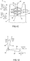
- a magnetic hybrid AMR/PHR based sensing device 2 is configured for detecting local magnitude and/or variation of a magnetic field generated remotely or closely by one or several magnetic source(s).
- the magnetic sensing device 2 comprises a magnetic field receiver 4 as a first component and a first magnetic field transmitter 6 as a second component, and a substrate 8 serving as support of the set formed by the magnetic field receiver 4 and the first magnetic field transmitter 6.
- the magnetic field receiver 4 has a structure of a magnetic hybrid AMR/PHR sensor and includes:
- the first magnetic field transmitter 6 is configured for being excited by a DC and/or AC current supplied by a bias current generator or by a time varying external magnetic field to be measured, and includes:
- the second track 40 of the first magnetic field transmitter is covered by a passivation layer 60.
- the magnetic field receiver 4 and the first magnetic field transmitter 6 are superimposed, secured to and separated by a first insulating spacer 62 configured to align respectively the first easy axis 18 and the first hard axis 28 to the second easy axis 48 and the second hard axis 58, then rotate the said second axis 48, 58, from the said first axis 18, 28 about a common perpendicular axis 64 at a predetermined fixed offset angle ⁇ , and to maintain this axis arrangement as well as a fixed separation distance e 12 between the first track 6 and the second track 8 in a range from few micrometers to few nanometers.
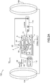
- the offset angle ⁇ formed between the firs easy axis 18 and the second easy axis, or equivalently between the first hard axis 28 and the second hard axis 58 is selected in the range [0 degree, 90 degree] so that the sensitivity of the magnetic sensor is maximal, and preferably is comprised within the range [15 degree, 25 degree] as shown in the Figure 1D .
- the offset angle ⁇ that optimizes the magnetic sensing device 2 is assumed to be equal 20 degrees.
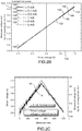
- an experimental system 102 for testing the behavior of the magnetic hybrid AMR/PHR based sensing device 2 comprises a sample unit to be tested 2 as defined in Figures 1A to 1D , a pair of Helmholtz coils 106, 108 configured to generate a magnetic driven field H AC oscillating at a predetermined frequency ⁇ applied in the vicinity of the sensing device 2 along the second hard axis of the first magnetic field transmitter, a bias current generator 112 to polarize the magnetic field receiver, and a measurement unit 114 connected to the voltage terminals 24, 26 of the AMR/PHR magnetic field receiver 4 and locked to a current signal taken at the current terminals 44, 46 of the track 40 of the first magnetic field transmitter 6.
- the two Helmholtz coils 16, 108 share and are connected to a driven current or voltage generator 118 configured to inject a DC+AC or AC driven current in the Helmholtz coils 16, 108, that can be translated into a driven voltage expressed in volts and ranging from -1.0 V (Volt) to +1.0 V (Volt) on a first abscissa axis in the Figure 2B .
- the magnetic field receiver and the first magnetic field transmitter are separated by a passivation layer forming the first spacer, the thickness thereof is comprised within 100nm to 1 ⁇ m and the diameter of the first magneto-resistive ring track is here equal to 600 ⁇ m.
- the evolution of the magneto-resistive voltage V MR measured by the sensing device 2 between the voltage terminals 24, 26 of the track 10 of the magnetic field receiver 4 and expressed in mV (milliVolt) on a second ordinate axis 134, versus the driven voltage, is plot in a set 138 of curves 142, 144, 146, 148, 150, 152 corresponding to a DC bias current injected through the current terminals 14, 16 of the AMR/PHR track 10 of the magnetic receiver 4 respectively equal to 0 mA, 0.1 mA, 0.5 mA, 1 mA, 2 mA and 5 mA.
- the measurements of the sensing voltage V MR achieved by using the test configuration of the Figure 2A indicate that the curves 142, 144, 146, 148, 150, 152 are almost the same and are therefore independent from the intensity of the bias current injected in the AMR/PHR track 1 of magnetic field receiver 4, the magnetic field receiver forming an actual sensor of a local magnetic field along the first hard axis and the first magnetic field transmitter forming a kind of local magnetic field lens.
- an alternative AC magnetic field H AC at a given frequency ⁇ induces an alternative current with the same frequency ⁇ for the receiver 4 of the sensing device 2.
- the amplitude of the induced current is proportional to the magnitude of the alternative magnetic field H AC .
- a direct DC bias current is injected into the magneto-resistive first track 10 of the receiver 4 through the first and second current terminals and a driven voltage is applied to the Helmholtz coils following a time varying triangular waveform 162.
- the corresponding evolution of the measured voltage V MR versus time t is illustrated by a curve 164.
- the sensing device 2 is configured to a avoid any injection of a direct DC bias current through the first and second current terminals by implementing an open circuit between the said first and second current terminals through an insulating material.
- the magnetic field receiver 4 can detect the induced collimated field generated by the track second track of the first magnetic field transmitter also without any supply power.
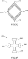
- the shape of the magnetic field receiver and the shape of the first magnetic field transmitter are shapes comprised in the set of the closed loop shapes among the shapes of a ring junction, a multi-ring junction, an oval junction, a multi-oval junction, a diamond junction, a multi-diamond junction, a square junction, a multi-square junction, a rectangular junction, a multi-rectangular junction, and the shape of a cross junction.
- a multi-ring junction 170 is illustrated in Figure 3A with a pair of current terminals 172, 174 and a pair of voltage terminals 176, 178.
- an oval junction 180 is illustrated in Figure 3B with a pair of current terminals 182, 184 and a pair of voltage terminals 186, 188.
- a square junction 190 is illustrated in Figure 3C with a pair of current terminals 192, 194 and a pair of voltage terminals 196, 198.
- a diamond junction 200 is illustrated in Figure 3D with a pair of current terminals 202, 204 and a pair of voltage terminals 206, 208.
- a multi-diamond junction 210 is illustrated in Figure 3E with a pair of current terminals 212, 214 and a pair of voltage terminals 216, 218.
- a cross junction 220 is illustrated in Figure 3F with a pair of current terminals 222, 224 and a pair of voltage terminals 226, 228.
- the first spacer is a bulky homogeneous layer made of a rigid insulating material.
- the spacer is a rigid structure made of a rigid insulating material having pillars and beams and/ or ribs, having voids filled by an insulating gas or vacuum.
- the first spacer is a bulky layer 232 made of a rigid insulating material and pierced with at least one longitudinal hole(s), here three longitudinal holes 234, 236, 238, directed along a direction 240 included in the extension plane of the layer 232, to drive magnetic particle(s) and without lateral opening.
- the direction of the longitudinal holes is chosen so that when the first spacer and the magnetic field receiver are integrated the first hard axis of the magneto-resistive first track and the extension direction of the longitudinal holes are parallel.
- the first spacer is a bulky layer 242 made of a rigid insulating material and pierced with at least one longitudinal hole(s), here a single longitudinal hole 244, directed along a direction 246 included in the extension plane of the layer, to drive magnetic particle(s).
- the longitudinal hole(s), here the single hole 244, have/has lateral(s) opening, here one lateral opening 248, connected to secondary longitudinal hole(s), here one se secondary longitudinal hole 250 in the Figure 4B , to provide a control access for controlling a magnetic state of the particle(s).
- the first spacer is a bulky layer 252 made of a rigid insulating material and pierced perpendicularly to the layer plane with at least one longitudinal hole(s), here a single longitudinal hole 254, at a predetermined location 256.
- the predetermined location 256 is determined so that the longitudinal hole 254 opens at one end to a central opening 258 of the second track 40 of the first magnetic field transmitter 6, when the second track 40 of the first transmitter 6 has such a central opening 258 and when the first spacer and the first magnetic field transmitter are integrated.
- the rigid insulating material of the first spacer is comprised among the dioxide of silicon SiO 2 .
- the thickness e 12 of the insulating layer of the first spacer is ranging from 1 ⁇ m to 5 ⁇ m, or from 600 nm to 1 ⁇ m, or from 200 nm to 600 nm, or from 50 nm to 200 nm, or from 10 nm to 50 nm, or from 1 nm to 10 nm.
- the material of the first track is a magneto-resistive material among the bi-layer structure material, in particular Ta/NiFe/IrMn/Ta, a tri-layer structure material including a ferromagnetic film, a metal and an anti-ferromagnetic film, in particular Ta/NiFe/Cu/IrMn/Ta, and a spin-valve structure material, in particular Ta/NiFe/Cu/NiFe/IrMn/Ta; and the material of the second track is a magneto-resistive material among a bi-layer structure material, in particular Ta/NiFe/IrMn/Ta, a tri-layer structure material including a ferromagnetic film, a metal and an anti-ferromagnetic film, in particular Ta/NiFe/Cu/IrMn/Ta, and a spin-valve structure material, in particular Ta/NiFe/Cu/
- the accuracy of the alignment of the axis before their rotation is below 10 nm and the accuracy of the set ⁇ angle is below 1,0 degree, preferably below 0, 02 degree.
- the magnetic field receiver 4 and the first magnetic field transmitter 5 are identical, or the magnetic field receiver 4 and the first magnetic field transmitter 6 mutually differ by the shape of their magnetic track, and/or the material of their electromagnetic track.
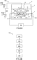
- a magnetic measuring system 262 comprises the magnetic hybrid AMR/PHR based sensing device 2 as described in the Figures 1A-1B , and a voltage measurement device 264 connected between the first and second voltage terminals.
- the magnetic measuring system 262 is configured for keeping disconnected the first pair of current terminals 14, 16 of the magnetic field receiver 4, the second pair of current terminals 44, 46 of the first magnetic field transmitter 6, and the second pair of voltage terminals 54, 56 so that the impedance between the first pair of current terminals 14, 16, the impedance between the second pair of current terminals 44, 46, the impedance between the second pair of voltage terminals are representative of open circuits.
- the voltage measurement device 264 comprises an amplifier circuit, connected to the first and second voltage terminals, for amplifying a measurement signal and/or cancelling an offset voltage from the said measurement signal.
- the amplifier is integrated within the magnetic sensing device 2.
- the magnetic measuring system 262 is well suited to measure local magnitude and/or variation of a time varying magnetic field, generated remotely or closely by one or several magnetic source(s) and to implement the magnetic measuring method according to the invention as described in the Figure 5B .
- a magnetic measuring method 302 comprises a first set of steps for measuring local magnitude and/or variation of a magnetic field generated remotely or closely by one or several magnetic source(s).
- a magnetic hybrid AMR/PHR based sensing device as described here above in the Figures 1A-1C and 4A-4C .
- the sensing device comprises a magnetic field receiver and a first magnetic field transmitter as described here above.
- a differential voltage V MR between the voltage terminals of the first pair is measured by a voltage measurement device connected between the first and second voltage terminals, while keeping disconnected the first pair of current terminals of the magnetic field receiver, the first pair of voltage terminals of the magnetic field receiver, and the second pair of current terminals of the first magnetic field transmitter, so that the impedance between the first pair of current terminals, the impedance between the first pair of voltage terminals, the impedance between the second pair of current terminals are representative of open circuits.
- a local magnitude and/or variation of a time varying magnetic field, generated remotely or closely by one or several magnetic source(s), is determined on the basis of the measured differential voltage.
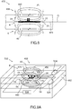
- a magnetic measuring system 322 comprises the magnetic hybrid MR/PHR based sensing device 2 as described in the Figures 1A-1B , one second track current source 324 for supplying a DC and/or AC current to the second track 40 of the first magnetic field transmitter 6 and a voltage measurement device 334, similar to the voltage measurement device 264 of the Figure 5A and connected between the first pair of voltage terminals 24, 26.
- the magnetic measuring system 322 is configured for keeping disconnected the first pair of current terminals 14, 16 of the magnetic field receiver 4, the second pair of voltage terminals 54, 56 so that the impedance between the first pair of current terminals 14, 16, the impedance between the second pair of voltage terminals 54, 56 are representative of open circuits.
- the voltage measurement device 334 comprises an amplifier circuit, connected to the first and second voltage terminals 24, 26, for amplifying a measurement signal and/or cancelling an offset voltage from the said measurement signal.
- the amplifier is integrated within the magnetic sensing device 2.
- the first spacer 342 is similar to a spacer among the described spacers of Figure 4A, 4B and 4C .
- Such a spacer 342 is configured to drive magnetic particles 348 in the vicinity and close to an active area of the magneto-resistive track 10 of the magnetic field receiver 4.
- the magnetic measuring system 322 is well suited to measure local magnitude and/or variation of a magnetic field, generated closely by one or several magnetic particles and to implement a magnetic measuring method according to a second method embodiment described in Figure 6B .
- the magnetic particles to be detected by the magnetic sensing device according to the invention are comprised in the family of:
- a magnetic measuring method 352 comprises a second set of steps for measuring local magnitude and/or variation of a magnetic field generated closely by one or several magnetic source(s).
- a magnetic hybrid AMR/PHR based sensing device 2 as described in the Figures 1A-1C and 4A-4C .
- the sensing device comprises a magnetic field receiver and a first magnetic field transmitter as described here above as well as a first spacer similar to one of the spacers of Figure 4A to 4C .
- a bias DC and/or AC current is injected in the electromagnetic second track 40 of the first magnetic field transmitter 6 by using an electrical bias current source connected between the third and fourth current terminals of the first magnetic field transmitter.
- a set of one or several magnetic particles sensitive to a magnetic field are driven in the vicinity or in contact of an active area of the magneto-resistive track of the magnetic field receiver, the active area being located under the electromagnetic second track of the first magnetic field transmitter.
- a differential voltage V MR between the first and second voltage terminals 24, 26 of the magnetic field receiver 4 is measured by a voltage measurement device connected between the first and second voltage terminals, while keeping disconnected the first pair of current terminals 14, 16 of the magnetic field receiver and the second pair of voltage terminals 54, 56 of the first magnetic field transmitter so that the impedance between the first pair of current terminals 14, 16, and the impedance between the second pair of voltage terminals 54, 56 are representative of open circuits.
- a local magnitude and/or variation of a magnetic field generated closely by the magnetic particles is determined on the basis of the measured differential voltage V MR .
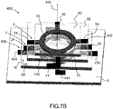
- a magnetic hybrid MR/PHR based sensing device 402 comprises the same following components of the magnetic sensing device 2 of Figures 1A-1B : the magnetic field receiver 4, the first magnetic field transmitter 6, the first spacer 62, the passivation layer 60, and the substrate 8.
- the magnetic field receiver 4, the first magnetic field transmitter 6 and the first spacer 62 of the magnetic sensing device 402 according the second device embodiment are also arranged in the same way as for the magnetic sensing device 2 of Figures 1A-1B according to the first embodiment.
- the magnetic sensing device 402 according to the second embodiment differs from the magnetic sensing device 2 according to the first embodiment in that it comprises further a second magnetic field transmitter 406 as a third component.
- the second magnetic field transmitter 406 is configured for being excited by a DC and/or AC supplied bias current or by an external magnetic field to be measured, and includes:
- the first magnetic field transmitter 6 and the second magnetic field transmitter 406 are identical.
- the first magnetic field transmitter 6, the magnetic field receiver 4 and the second magnetic field transmitter 406 are superimposed and mutually secured through the first spacer 62 and a second spacer 462 so that the field magnetic receiver 4 is sandwiched between the first field magnetic transmitter 6 and the second field magnetic transmitter 106.
- the second insulating spacer 462 is configured to secure the second magnetic field transmitter 406 to the magnetic field receiver 4 on the opposite side of the first insulating spacer 62, once performed an alignment of the respective first easy axis 18 and the first hard axis 28 to the respective third easy axis 448 and the third hard axis 458, followed by a rotation of the said third axis 448, 458 from the said first axis 18, 28 about the common perpendicular axis 464 at the same predetermined fixed offset angle ⁇ of the Figures 1A-1D , and is configured to maintain this axis arrangement as well as a fixed separation distance e 13 between the first track 10 and the third track 440 equal to the fixed separation distance e 12 between the first track and the second track.
- the second spacer 462 is a bulky homogeneous layer made of the same rigid insulating material as the insulating material of the first spacer 62.
- the whole sandwich structure formed by the second magnetic field transmitter 406, the second spacer 462, the magnetic field receiver 4, the first spacer 62, the first magnetic field transmitter and the optional passivation layer, is supported by the substrate 8 through the second magnetic field transmitter 6 and the second spacer 462.
- the magnetic sensing device 402 can be used in a differential mode to detect with a high sensitivity the variation of the magnetic field close to the surface of the first track of the magnetic field receiver when magnetic particles are driven close to and above the said surface in Figure 8 .
- the tracks 40, 440 of the magnetic field transmitters can be only low resistive track made of a material such as copper, aluminum, gold or silver for example to enhance magnetic field.
- a magnetic measuring system 502 comprises the magnetic hybrid MR/PHR based sensing device 402 as described in the Figures 7A-7B , a second track current source 524 and a third track current source 526 for supplying a DC and/or AC current respectively to the second track 40 of the first magnetic field transmitter 6 and the third track 440 of the second magnetic field transmitter 406, and a voltage measurement device 534, similar to the voltage measurement devices 264, 334 of the Figures 5A and 6A and connected between the first pair of voltage terminals 24, 26.
- the magnetic measuring system 502 is configured for keeping disconnected the first pair of current terminals 14, 16 of the magnetic field receiver 4, the second pair of voltage terminals 54, 56, and the third pair of voltage terminals 454, 456, so that the impedance between the first pair of current terminals 14, 16, the impedance between the second pair of voltage terminals 54, 56, the impedance between the third pair of voltage terminals 454, 456 are representative of open circuits.
- the second track current source 524 and the third track current source 526 are configured and connected to the second track of the first magnetic field transmitter and to the third track of the second magnetic field transmitter in order to generate two magnetic fields, symmetric to the plane of the magnetic field receiver and polarized with opposite direction.
- the voltage measurement device 434 comprises an amplifier circuit, connected to the first and second voltage terminals 24, 26, for amplifying a measurement signal and/or cancelling an offset voltage from the said measurement signal.
- the amplifier is integrated within the magnetic sensing device 402.
- first spacer 462 is similar to a spacer among the described spacers of Figure 4A, 4B and 4C .
- Such a spacer 462 is configured to drive magnetic particles 508 in the vicinity and close to an active area of the magneto-resistive track 10 of the magnetic field receiver 4.
- the magnetic measuring system 502 is well suited to measure local magnitude and/or variation of a magnetic field, generated closely by one or several magnetic particles and to implement a magnetic measuring method according to a third method embodiment described in Figure 9B .
- the magnetic particles that can be detected by the third magnetic measuring system are the same magnetic particles that can be detected by the magnetic measuring system of Figure 6A and are listed in description of the Figure 6A .
- a magnetic measuring method 582 comprises a third set of steps for measuring local magnitude and/or variation of a magnetic field generated closely by one or several magnetic source(s).
- a magnetic hybrid AMR/PHR based sensing device 402 according to the second device embodiment as described in the Figures 7A-7B is provided.
- the magnetic sensing device 402 comprises a magnetic field receiver 4, a first magnetic field transmitter 6 and a second magnetic field transmitter 406.
- the magnetic sensing device 402 is configured to operate in a differential mode.
- a bias DC and/or AC current is injected in the second electromagnetic track of the first magnetic field transmitter and in the third magnetic track of the second magnetic field transmitter by using an electrical bias current source, connected between the third and fourth current terminals of the first magnetic field transmitter and between the fifth and the sixth current terminals of the second magnetic field transmitter, so that the excitation magnetic fields generated by the first magnetic field transmitter and the second magnetic field transmitter are polarized on opposite direction.
- a set of one or several magnetic particles sensitive to a magnetic field are driven in the vicinity or in contact of an active area of the magnetic receiver 4 located under the electromagnetic track 40 of the first magnetic field transmitter 6.
- a differential voltage V MR between the first and second voltage terminals 24, 26 of the magnetic field receiver 4 is measured by a voltage measurement device, connected between the first and second voltage terminals 24, 26, while keeping disconnected the first pair of current terminals of the magnetic field receiver and the second pair of voltage terminals of the first magnetic field transmitter so that the impedance between the first pair of current terminals, and the impedance between the second pair of voltage terminals are representative of an open circuit;
- a local magnitude and/or a variation of a time varying magnetic field generated closely by the magnetic particles are determined on the basis of the measured differential voltage V MR .
- the sensing device, the magnetic measuring system, the magnetic measuring method according to the various embodiments as described here above can be used to detect and quantify a known time varying (in particular AC) magnetic field source or to detect an unknown time varying (in particular AC) magnetic field from other noise sources. There is no need to drive an electric power to the magneto-resistive AMR/HR sensor for detecting the time varying magnetic field.
- the use of the sensing device according to the invention can be broadened up to many fields of application requiring low power consumption sensing devices such as robotic and space applications.
- the magnetic field receiver is used to detect the presence of the gas through a magnetic field change caused the magnetic particle(s) deposited on the sensing surface of its AMR/PHR track, while the first magnetic field transmitter is configured to generate the magnetic field.
- the magnetic field receiver operating as a detector detects the magnetic field signal without need of a power supply and generating an undesired thermal noise caused by a resistive Joule effect.
- the sensing device of the invention permits a decrease of its power consumption while detecting a local magnetic field with high sensitivity.
- new applications are rendered possible to AMR/PHR sensors requiring low power consumption.
- the magnetic field sensing device according to the invention can be used for following applications:
- the sensing device is a low power consumption, small and compact device by saving the weight of the power stage supply and by allowing an operation at temperatures ranging from 4°K to 400°K.
- the sensing device operates within large frequency range from 1 to 10 kHz without Joule effect dissipation and any heating process.
- the sensing device according to the invention is less bulky than the conventional inductance of flux gate.
- the size of the sensing device is the order of the micrometer for the AMR/PHR itself and the order of the cm 3 for the packaging.
- the magnetic sensing device of the invention is easy to manufacture, which permits a low cost production rate for a mass production.
Landscapes
- Physics & Mathematics (AREA)
- Condensed Matter Physics & Semiconductors (AREA)
- General Physics & Mathematics (AREA)
- Measuring Magnetic Variables (AREA)
Claims (15)
- Dispositif de détection basé sur une magnétorésistance/une résistance à effet Hall planaire, AMR/PHR, hybride magnétique pour détecter une amplitude locale et/ou une variation d'un champ magnétique généré à distance ou à proximité par une ou plusieurs sources magnétiques, et comprenant :- un récepteur de champ magnétique (4), en tant que premier composant, présentant une structure d'un capteur à magnétorésistance/résistance à effet Hall planaire, AMR/PHR, hybride magnétique, et qui inclutdans lequel• une première piste magnétorésistive (10) présentant une forme de boucle fermée ou une forme de jonction transversale ;• une première paire (12) de bornes de courant, formée avec une première borne de courant (14) et une deuxième borne de courant (16), qui se font mutuellement face, en contact avec la première piste magnétorésistive (10) et formant un premier axe aisé (18) ;• une première paire (22) de bornes de tension formée avec une première borne de tension (24) et une deuxième borne de tension (26), qui se font mutuellement face, en contact avec la première piste magnétorésistive (10) et formant un premier axe difficile (28), orthogonal au premier axe aisé (18),
le dispositif de détection basé sur une magnétorésistance/une résistance à effet Hall planaire, AMR/PHR, hybride magnétique comprend :- un premier émetteur de champ magnétique (6), en tant que deuxième composant, configuré pour être excité par un courant de polarisation alimenté en courant continu et/ou en courant alternatif ou par un champ magnétique externe à mesurer, et qui inclut :• une deuxième piste magnétorésistive ou faiblement résistive (40) présentant une forme de boucle fermée ou une boucle de jonction transversale ;• une deuxième paire (42) de bornes de courant formée avec une troisième borne de courant (44) et une quatrième borne de courant (46), qui se font mutuellement face, en contact avec la deuxième piste (40) et formant un deuxième axe aisé (48) ;• une deuxième paire (52) de bornes de tension formée avec une troisième borne de tension (54) et une quatrième borne de tension (56), qui se font mutuellement face, en contact avec la deuxième piste (40) et formant un deuxième axe difficile (58), orthogonal au deuxième axe aisé (48) ;
caractérisé en ce que :
le récepteur de champ magnétique (4) et l'émetteur de champ magnétique (6) sont superposés, fixés à, et séparés par un premier élément d'espacement isolant (62) configuré pour aligner respectivement le premier axe aisé (18) et le premier axe difficile (28) sur le deuxième axe aisé (48) et le deuxième axe difficile (58), et ensuite à faire tourner ledit deuxième axe (48, 58) par rapport audit premier axe (18, 28) selon un angle de décalage fixe prédéterminé a, et à maintenir cet agencement d'axes ainsi qu'une distance de séparation fixe e12 entre la première piste (10) et la deuxième piste (40) dans une plage allant de quelques micromètres à quelques nanomètres. - Dispositif de détection basé sur une magnétorésistance/une résistance à effet Hall planaire, AMR/PHR, hybride magnétique selon la revendication 1, dans lequel le premier élément d'espacement (62) est :- une structure rigide constituée d'un matériau isolant rigide présentant des piliers et des poutres et/ou des nervures, présentant des vides remplis par un gaz isolant ou un vide ; ou- une couche homogène volumineuse constituée d'un matériau isolant rigide ; ou- une couche volumineuse (232) constituée d'un matériau isolant rigide, et percée d'au moins un ou plusieurs trous longitudinaux (234, 236, 238), orientés le long d'une direction (240) incluse dans le plan d'extension de la couche, pour entraîner une ou des particules magnétiques, et sans ouverture latérale ; ou- une couche volumineuse (242) constituée d'un matériau isolant rigide, et percée d'au moins un ou plusieurs trous longitudinaux (244), orientés le long d'une direction (246) incluse dans le plan d'extension de la couche (242), pour entraîner une ou des particules magnétiques, le ou les trous longitudinaux (244) présentant une ou des ouvertures latérales (248) reliées à un ou des trous longitudinaux secondaires (250) en vue de fournir un accès de contrôle pour contrôler un état magnétique de la ou des particules ; ou- une couche volumineuse (252) constituée d'un matériau isolant rigide, et percée, perpendiculairement au plan de couche, d'au moins un ou plusieurs trous longitudinaux (254), lorsque la deuxième piste (40) du premier émetteur (6) présente une ouverture centrale (258).
- Dispositif de détection basé sur une magnétorésistance/une résistance à effet Hall planaire, AMR/PHR, hybride magnétique selon l'une quelconque des revendications 1 à 2, dans lequel
le matériau isolant rigide du premier élément d'espacement (62) est compris parmi le dioxyde de silicium, SiO2; et/ou
l'épaisseur e12 de la couche isolante du premier élément d'espacement (62) est comprise entre 1 µm et 5 µm, ou entre 600 nm et 1 µm, ou entre 200 nm et 600 nm, ou entre 50 nm et 200 nm, ou entre 10 nm et 50 nm, ou entre 1 nm et 10 nm. - Dispositif de détection basé sur une magnétorésistance/une résistance à effet Hall planaire, AMR/PHR, hybride magnétique selon l'une quelconque des revendications 1 à 3, dans lequel la forme de la piste (10) du récepteur de champ magnétique (4) et la forme de la piste (40) du premier émetteur de champ magnétique (6) sont des formes comprises dans l'ensemble des formes de boucle fermée parmi les formes d'une jonction annulaire, d'une jonction à anneaux multiples (170), d'une jonction ovale (180), d'une jonction à ovales multiples, d'une jonction diamant (200), d'une jonction à diamants multiples (210), d'une jonction carrée (200), d'une jonction à carrés multiples, d'une jonction rectangulaire, d'une jonction multi-rectangulaire, et la forme d'une jonction transversale (220).
- Dispositif de détection basé sur une magnétorésistance/une résistance à effet Hall planaire, AMR/PHR, hybride magnétique selon l'une quelconque des revendications 1 à 4, dans lequel :le matériau de la première piste (10) est un matériau magnétorésistif parmi le matériau de structure bicouche, en particulier Ta/NiFe/IrMn/Ta, un matériau de structure à trois couches incluant un film ferromagnétique, un métal et un film antiferromagnétique, en particulier Ta/NiFe/Cu/IrMn/Ta, et un matériau de structure à vanne de spin, en particulier Ta/NiFe/Cu/NiFe/IrMn/Ta ; etle matériau de la deuxième piste (40) est un matériau magnétorésistif parmi un matériau de structure bicouche, en particulier Ta/NiFe/IrMn/Ta, un matériau de structure à trois couches incluant un film ferromagnétique, un métal et un film antiferromagnétique, en particulier Ta/NiFe/Cu/IrMn/Ta, et un matériau de structure à vanne de spin, en particulier Ta/NiFe/Cu/NiFe/IrMn/Ta, ou est un matériau faiblement résistif parmi les métaux suivants : l'or, le cuivre et l'argent.
- Dispositif de détection basé sur une magnétorésistance/une résistance à effet Hall planaire, AMR/PHR, hybride magnétique selon l'une quelconque des revendications 1 à 5, dans lequel l'angle de décalage α formé entre le premier axe aisé (18) du récepteur de champ magnétique et le deuxième axe aisé (48) du premier émetteur de champ magnétique est sélectionné dans la plage [0 degré, 90 degrés], de sorte que la sensibilité du dispositif de détection est maximale, et est de préférence compris dans la plage [15 degrés, 25 degrés].
- Dispositif de détection basé sur une magnétorésistance/une résistance à effet Hall planaire, AMR/PHR, hybride magnétique selon l'une quelconque des revendications 1 à 6, dans lequel la précision de l'alignement de l'axe avant sa rotation est inférieure à 10 nm, et la précision de l'angle de décalage α est inférieure à 1,0 degré, de préférence inférieure à 0,02 degré.
- Dispositif de détection basé sur une magnétorésistance/une résistance à effet Hall planaire, AMR/PHR, hybride magnétique selon l'une quelconque des revendications 1 à 7, dans lequel :le récepteur de champ magnétique (4) et le premier émetteur de champ magnétique (6) sont identiques ; oule récepteur de champ magnétique (4) et le premier émetteur de champ magnétique (6) diffèrent mutuellement par la forme de leur piste électromagnétique (10, 40), et/ou par le matériau de leur piste électromagnétique (10, 40).
- Dispositif de détection basé sur une magnétorésistance/une résistance à effet Hall planaire, AMR/PHR, hybride magnétique selon l'une quelconque des revendications 1 à 8, comprenant en outre :- un second émetteur de champ magnétique (406), en tant que troisième composant, configuré pour être excité par un courant de polarisation alimenté en courant continu et/ou en courant alternatif ou par un champ magnétique externe à mesurer, et qui inclut :• une troisième piste magnétorésistive ou faiblement résistive (440) présentant une forme de boucle fermée ou une forme de jonction transversale ;• une troisième paire (442) de bornes de courant formée avec une cinquième borne de courant (444) et une sixième borne de courant (446), qui se font mutuellement face, en contact avec la troisième piste (440) et formant un troisième axe aisé (448) ;• une troisième paire (452) de bornes de tension formée avec une cinquième borne de tension (454) et une sixième borne de tension (456), qui se font mutuellement face, en contact avec la troisième piste (440) et formant un troisième axe difficile (458), orthogonal au troisième axe aisé (448) ; et
dans lequel
le premier émetteur de champ magnétique (6) et le second émetteur de champ magnétique (406) sont identiques ; et
le premier émetteur de champ magnétique (6), le récepteur de champ magnétique (4) et le second émetteur de champ magnétique (406) sont superposés et mutuellement fixés à travers le premier élément d'espacement (62) et un deuxième élément d'espacement (462), de sorte que le récepteur de champ magnétique (4) est pris en sandwich entre le premier émetteur de champ magnétique (6) et le second émetteur de champ magnétique (406). - Dispositif de détection basé sur une magnétorésistance/une résistance à effet Hall planaire, AMR/PHR, hybride magnétique selon la revendication 9, dans lequel
le deuxième élément d'espacement isolant (462) est configuré pour fixer le second émetteur de champ magnétique (406) au récepteur de champ magnétique (4) sur le côté opposé du premier élément d'espacement isolant (62), dès lors qu'est obtenu un alignement respectif du premier axe aisé (18) et du premier axe difficile (28) avec respectivement le troisième axe aisé (448) et le troisième axe difficile (458), suivi d'une rotation dudit troisième axe par rapport audit premier axe selon l'angle de décalage fixe prédéterminé a, et à maintenir cet agencement d'axes ainsi qu'une distance de séparation fixe e13 entre la première piste (10) et la troisième piste (440) égale à la distance de séparation fixe e12 entre la première piste (10) et la deuxième piste (40) ; et
le deuxième élément d'espacement (462) est une couche homogène volumineuse constituée du matériau isolant rigide en tant que matériau isolant du premier élément d'espacement (62). - Dispositif de détection basé sur une magnétorésistance/une résistance à effet Hall planaire, AMR/PHR, hybride magnétique selon l'une quelconque des revendications 1 à 10, comprenant en outre :soit une unique source de courant de deuxième piste (324) pour fournir un courant continu et/ou un courant alternatif à la deuxième piste (40) du premier émetteur de champ magnétique (6) lorsque le dispositif de détection magnétique comprend le récepteur de champ magnétique et le premier émetteur de champ magnétique en tant qu'un unique émetteur de champ magnétique ;soit une source de courant de deuxième piste (524) et une source de courant de troisième piste (526) pour fournir un courant continu et/ou un courant alternatif, respectivement, à la deuxième piste (40) du premier émetteur de champ magnétique (6) et à la troisième piste (440) du second émetteur de champ magnétique (406), lorsque le dispositif de détection magnétique comprend le récepteur de champ magnétique et deux premiers et seconds émetteurs de champ magnétique en vue de fonctionner en mode différentiel, la source de courant de deuxième piste et la source de courant de troisième piste étant configurées et reliées à la deuxième piste du premier émetteur de champ magnétique et à la troisième piste du second émetteur de champ magnétique afin de générer deux champs magnétiques, symétriques au plan du récepteur de champ magnétique et polarisés en sens inverse.
- Dispositif de détection basé sur une magnétorésistance/une résistance à effet Hall planaire, AMR/PHR, hybride magnétique selon l'une quelconque des revendications 1 à 11, comprenant en outre un circuit amplificateur connecté aux première et deuxième bornes de tension en vue d'amplifier un signal de mesure et/ou d'annuler une tension de décalage par rapport audit signal de mesure.
- Procédé de mesure magnétique pour mesurer une amplitude locale et/ou une variation d'un champ magnétique généré à distance ou à proximité par une ou plusieurs sources magnétiques,
le procédé de mesure magnétique comprenant les étapes ci-dessous consistant à :- fournir (304) un dispositif de détection basé sur une magnétorésistance/une résistance à effet Hall planaire, AMR/PHR, hybride magnétique (2), comprenant un récepteur de champ magnétique (4) et un premier émetteur de champ magnétique (6) selon l'une quelconque des revendications 1 à 8 ;- mesurer (306) une tension différentielle VMR entre les bornes de tension de la première paire en utilisant un dispositif de mesure de tension connecté entre les première et deuxième bornes de tension, tout en maintenant déconnectées la première paire de bornes de courant du récepteur de champ magnétique, la première paire de bornes de tension du récepteur de champ magnétique, et la deuxième paire de bornes de courant du premier émetteur de champ magnétique, de sorte que l'impédance entre les bornes de la première paire de bornes de courant, l'impédance entre les bornes de la première paire de bornes de tension et l'impédance entre les bornes de la deuxième paire de bornes de courant sont représentatives d'un circuit ouvert ;- déterminer (308) une amplitude locale et/ou une variation d'un champ magnétique instationnaire généré à distance ou à proximité par une ou plusieurs sources magnétiques sur la base de la tension différentielle mesurée. - Procédé de mesure magnétique pour mesurer une amplitude locale et/ou une variation d'un champ magnétique généré à proximité par une ou plusieurs sources magnétiques,
le procédé de mesure magnétique comprenant les étapes ci-dessous consistant à :- fournir (354) un dispositif de détection basé sur une magnétorésistance/une résistance à effet Hall planaire, AMR/PHR, hybride magnétique comprenant un récepteur de champ magnétique et un premier émetteur de champ magnétique selon l'une quelconque des revendications 1 à 8 ;- injecter (356) un courant continu et/ou un courant alternatif de polarisation dans la deuxième piste magnétique du premier émetteur de champ magnétique, en utilisant une source de courant de polarisation électrique connectée entre les troisième et quatrième bornes de courant du premier émetteur de champ magnétique ; et- conduire (358) un ensemble d'une ou plusieurs particules magnétiques sensibles à un champ magnétique à proximité de ou en contact avec une zone active, du récepteur de champ magnétique, située sous la piste magnétique du premier émetteur de champ magnétique ; et ensuite- mesurer (360) une tension différentielle VMR entre les première et deuxième bornes de tension du récepteur de champ magnétique, en utilisant un dispositif de mesure de tension connecté entre les première et deuxième bornes de tension, tout en maintenant déconnectées la première paire de bornes de courant du récepteur de champ magnétique et la deuxième paire de bornes de tension du premier émetteur de champ magnétique, de sorte que l'impédance entre les bornes de la première paire de bornes de courant et l'impédance entre les bornes de la deuxième paire de bornes de tension sont représentatives d'un circuit ouvert ;- déterminer (362) une amplitude locale et/ou une variation d'un champ magnétique instationnaire généré à proximité par les particules magnétiques sur la base de la tension différentielle mesurée. - Procédé de mesure magnétique pour mesurer une amplitude locale et/ou une variation d'un champ magnétique généré à proximité par une ou plusieurs sources magnétiques,
le procédé de mesure magnétique comprenant les étapes ci-dessous consistant à :- fournir (584) un dispositif de détection basé sur une magnétorésistance/une résistance à effet Hall planaire, AMR/PHR, hybride magnétique, comprenant un récepteur de champ magnétique, un premier émetteur de champ magnétique et un second émetteur de champ magnétique selon l'une quelconque des revendications 9 à 10 ;- injecter (586) un courant continu et/ou un courant alternatif de polarisation dans la deuxième piste magnétique du premier émetteur de champ magnétique et dans la troisième piste magnétique du second émetteur de champ magnétique, en utilisant une source de courant de polarisation électrique connectée entre les troisième et quatrième bornes de courant du premier émetteur de champ magnétique et entre les cinquième et sixième bornes de courant du second émetteur de champ magnétique, de sorte que les champs magnétiques d'excitation générés par le premier émetteur de champ magnétique et le second émetteur de champ magnétique sont polarisés en sens inverse ; et- conduire (588) un ensemble d'une ou plusieurs particules magnétiques sensibles à un champ magnétique à proximité de ou en contact avec une zone active, du récepteur de champs magnétique, située sous la piste magnétique du premier émetteur de champ magnétique ; et ensuite- mesurer (590) une tension différentielle VMR entre les première et deuxième bornes de tension du récepteur de champ magnétique, en utilisant un dispositif de mesure de tension connecté entre les première et deuxième bornes de tension, tout en maintenant déconnectées la première paire de bornes de courant du récepteur de champ magnétique et la deuxième paire de bornes de tension du premier émetteur de champ magnétique, de sorte que l'impédance entre les bornes de la première paire de bornes de courant et l'impédance entre les bornes de la deuxième paire de bornes de tension sont représentatives d'un circuit ouvert ;- déterminer (592) une amplitude locale et/ou une variation d'un champ magnétique instationnaire généré à proximité par les particules magnétiques, sur la base de la tension différentielle mesurée.
Priority Applications (2)
| Application Number | Priority Date | Filing Date | Title |
|---|---|---|---|
| EP17305787.8A EP3418759B1 (fr) | 2017-06-23 | 2017-06-23 | Dispositif de détection basé sur amr/phr hybride magnétique et procédé de mesure d'un champ magnétique local |
| PCT/EP2018/066559 WO2018234435A1 (fr) | 2017-06-23 | 2018-06-21 | Dispositif de détection à base d'amr/phr hybride magnétique et procédé de mesure d'un champ magnétique local |
Applications Claiming Priority (1)
| Application Number | Priority Date | Filing Date | Title |
|---|---|---|---|
| EP17305787.8A EP3418759B1 (fr) | 2017-06-23 | 2017-06-23 | Dispositif de détection basé sur amr/phr hybride magnétique et procédé de mesure d'un champ magnétique local |
Publications (2)
| Publication Number | Publication Date |
|---|---|
| EP3418759A1 EP3418759A1 (fr) | 2018-12-26 |
| EP3418759B1 true EP3418759B1 (fr) | 2020-02-19 |
Family
ID=59966685
Family Applications (1)
| Application Number | Title | Priority Date | Filing Date |
|---|---|---|---|
| EP17305787.8A Active EP3418759B1 (fr) | 2017-06-23 | 2017-06-23 | Dispositif de détection basé sur amr/phr hybride magnétique et procédé de mesure d'un champ magnétique local |
Country Status (2)
| Country | Link |
|---|---|
| EP (1) | EP3418759B1 (fr) |
| WO (1) | WO2018234435A1 (fr) |
Families Citing this family (2)
| Publication number | Priority date | Publication date | Assignee | Title |
|---|---|---|---|---|
| CN110680319B (zh) * | 2019-10-25 | 2020-08-14 | 深圳技术大学 | 用于生物组织检测的磁感应分子成像方法及系统 |
| CN120447070B (zh) * | 2025-07-08 | 2025-09-12 | 西北工业大学 | 一种基于三层电阻网络模型的救援井井下磁场预测方法 |
Family Cites Families (2)
| Publication number | Priority date | Publication date | Assignee | Title |
|---|---|---|---|---|
| KR101093776B1 (ko) * | 2010-01-21 | 2011-12-19 | 충남대학교산학협력단 | 자기 센서 |
| EP2685273A1 (fr) * | 2012-07-13 | 2014-01-15 | Université Montpellier 2, Sciences et Techniques | Système et procédé de détection micromagnétometrique permettant de détecter des signatures magnétiques de matériaux magnétiques |
-
2017
- 2017-06-23 EP EP17305787.8A patent/EP3418759B1/fr active Active
-
2018
- 2018-06-21 WO PCT/EP2018/066559 patent/WO2018234435A1/fr not_active Ceased
Non-Patent Citations (1)
| Title |
|---|
| None * |
Also Published As
| Publication number | Publication date |
|---|---|
| EP3418759A1 (fr) | 2018-12-26 |
| WO2018234435A1 (fr) | 2018-12-27 |
Similar Documents
| Publication | Publication Date | Title |
|---|---|---|
| Tumanski | Modern magnetic field sensors–a review | |
| Khan et al. | Magnetic sensors-A review and recent technologies | |
| Yan et al. | Developments and applications of tunneling magnetoresistance sensors | |
| Roy et al. | Development of a very high sensitivity magnetic field sensor based on planar Hall effect | |
| US9519036B2 (en) | Magnetic sensor including magnetic layer of closed loop shape | |
| CN104969085B (zh) | 用于检测磁性材料的磁性特征的微磁力测定检测系统和方法 | |
| US6166539A (en) | Magnetoresistance sensor having minimal hysteresis problems | |
| US8129988B2 (en) | Method and system for adjusting the sensitivity of a magnetoresistive sensor | |
| Ripka et al. | AC-driven AMR and GMR magnetoresistors | |
| US20100328799A1 (en) | Spin Torque Oscillator Sensor | |
| JP2015524919A5 (fr) | ||
| Su et al. | Linear anisotropic magnetoresistive sensor without barber-pole electrodes | |
| Nguyen et al. | Exchange biased spin valve-based gating flux sensor | |
| JP2008064499A (ja) | 磁気センサー | |
| EP3418759B1 (fr) | Dispositif de détection basé sur amr/phr hybride magnétique et procédé de mesure d'un champ magnétique local | |
| Lamichhane et al. | Half bridge configurated magneto-resistive sensors with flux guide structure for enhancing sensitivity | |
| Guitard et al. | Local nuclear magnetic resonance spectroscopy with giant magnetic resistance-based sensors | |
| JP2016505834A (ja) | 広ダイナミックレンジ磁力計 | |
| Zhou et al. | Research progress of current sensor based on spin-dependent magnetoresistance effect | |
| WO2019093964A9 (fr) | Capteur de magnétoresitance avec polarisation de courant alternatif et détection de redressement | |
| Hristoforou | New monolithic three dimensional field sensors with high sensitivity | |
| RU2850747C1 (ru) | Многокомпонентный детектор переменного поля | |
| JP2016096377A (ja) | マイクロ波検波器及びマイクロ波検波方法 | |
| Kim et al. | Operating field optimization of giant magneto impedance (GMI) devices in micro scale for magnetic bead detection | |
| Ripka et al. | Advances in magnetic sensors |
Legal Events
| Date | Code | Title | Description |
|---|---|---|---|
| PUAI | Public reference made under article 153(3) epc to a published international application that has entered the european phase |
Free format text: ORIGINAL CODE: 0009012 |
|
| STAA | Information on the status of an ep patent application or granted ep patent |
Free format text: STATUS: THE APPLICATION HAS BEEN PUBLISHED |
|
| AK | Designated contracting states |
Kind code of ref document: A1 Designated state(s): AL AT BE BG CH CY CZ DE DK EE ES FI FR GB GR HR HU IE IS IT LI LT LU LV MC MK MT NL NO PL PT RO RS SE SI SK SM TR |
|
| AX | Request for extension of the european patent |
Extension state: BA ME |
|
| STAA | Information on the status of an ep patent application or granted ep patent |
Free format text: STATUS: REQUEST FOR EXAMINATION WAS MADE |
|
| 17P | Request for examination filed |
Effective date: 20190603 |
|
| RBV | Designated contracting states (corrected) |
Designated state(s): AL AT BE BG CH CY CZ DE DK EE ES FI FR GB GR HR HU IE IS IT LI LT LU LV MC MK MT NL NO PL PT RO RS SE SI SK SM TR |
|
| GRAP | Despatch of communication of intention to grant a patent |
Free format text: ORIGINAL CODE: EPIDOSNIGR1 |
|
| STAA | Information on the status of an ep patent application or granted ep patent |
Free format text: STATUS: GRANT OF PATENT IS INTENDED |
|
| RIC1 | Information provided on ipc code assigned before grant |
Ipc: G01R 33/07 20060101ALI20190910BHEP Ipc: G01R 33/09 20060101AFI20190910BHEP |
|
| INTG | Intention to grant announced |
Effective date: 20191008 |
|
| RIN1 | Information on inventor provided before grant (corrected) |
Inventor name: KAMARA, SOULEYMANE Inventor name: KIM, M. CHEOLGI Inventor name: FELIX, GAUTIER Inventor name: TERKI, FERIAL Inventor name: TRAN, QUANG-HUNG Inventor name: BOUSSEKSOU, AZZEDINE |
|
| GRAS | Grant fee paid |
Free format text: ORIGINAL CODE: EPIDOSNIGR3 |
|
| GRAA | (expected) grant |
Free format text: ORIGINAL CODE: 0009210 |
|
| STAA | Information on the status of an ep patent application or granted ep patent |
Free format text: STATUS: THE PATENT HAS BEEN GRANTED |
|
| AK | Designated contracting states |
Kind code of ref document: B1 Designated state(s): AL AT BE BG CH CY CZ DE DK EE ES FI FR GB GR HR HU IE IS IT LI LT LU LV MC MK MT NL NO PL PT RO RS SE SI SK SM TR |
|
| REG | Reference to a national code |
Ref country code: CH Ref legal event code: EP |
|
| REG | Reference to a national code |
Ref country code: DE Ref legal event code: R096 Ref document number: 602017011953 Country of ref document: DE |
|
| REG | Reference to a national code |
Ref country code: AT Ref legal event code: REF Ref document number: 1235575 Country of ref document: AT Kind code of ref document: T Effective date: 20200315 |
|
| REG | Reference to a national code |
Ref country code: IE Ref legal event code: FG4D |
|
| REG | Reference to a national code |
Ref country code: NL Ref legal event code: MP Effective date: 20200219 |
|
| PG25 | Lapsed in a contracting state [announced via postgrant information from national office to epo] |
Ref country code: NO Free format text: LAPSE BECAUSE OF FAILURE TO SUBMIT A TRANSLATION OF THE DESCRIPTION OR TO PAY THE FEE WITHIN THE PRESCRIBED TIME-LIMIT Effective date: 20200519 Ref country code: FI Free format text: LAPSE BECAUSE OF FAILURE TO SUBMIT A TRANSLATION OF THE DESCRIPTION OR TO PAY THE FEE WITHIN THE PRESCRIBED TIME-LIMIT Effective date: 20200219 Ref country code: RS Free format text: LAPSE BECAUSE OF FAILURE TO SUBMIT A TRANSLATION OF THE DESCRIPTION OR TO PAY THE FEE WITHIN THE PRESCRIBED TIME-LIMIT Effective date: 20200219 |
|
| REG | Reference to a national code |
Ref country code: LT Ref legal event code: MG4D |
|
| PG25 | Lapsed in a contracting state [announced via postgrant information from national office to epo] |
Ref country code: IS Free format text: LAPSE BECAUSE OF FAILURE TO SUBMIT A TRANSLATION OF THE DESCRIPTION OR TO PAY THE FEE WITHIN THE PRESCRIBED TIME-LIMIT Effective date: 20200619 Ref country code: GR Free format text: LAPSE BECAUSE OF FAILURE TO SUBMIT A TRANSLATION OF THE DESCRIPTION OR TO PAY THE FEE WITHIN THE PRESCRIBED TIME-LIMIT Effective date: 20200520 Ref country code: HR Free format text: LAPSE BECAUSE OF FAILURE TO SUBMIT A TRANSLATION OF THE DESCRIPTION OR TO PAY THE FEE WITHIN THE PRESCRIBED TIME-LIMIT Effective date: 20200219 Ref country code: BG Free format text: LAPSE BECAUSE OF FAILURE TO SUBMIT A TRANSLATION OF THE DESCRIPTION OR TO PAY THE FEE WITHIN THE PRESCRIBED TIME-LIMIT Effective date: 20200519 Ref country code: LV Free format text: LAPSE BECAUSE OF FAILURE TO SUBMIT A TRANSLATION OF THE DESCRIPTION OR TO PAY THE FEE WITHIN THE PRESCRIBED TIME-LIMIT Effective date: 20200219 Ref country code: SE Free format text: LAPSE BECAUSE OF FAILURE TO SUBMIT A TRANSLATION OF THE DESCRIPTION OR TO PAY THE FEE WITHIN THE PRESCRIBED TIME-LIMIT Effective date: 20200219 |
|
| PG25 | Lapsed in a contracting state [announced via postgrant information from national office to epo] |
Ref country code: NL Free format text: LAPSE BECAUSE OF FAILURE TO SUBMIT A TRANSLATION OF THE DESCRIPTION OR TO PAY THE FEE WITHIN THE PRESCRIBED TIME-LIMIT Effective date: 20200219 |
|
| PG25 | Lapsed in a contracting state [announced via postgrant information from national office to epo] |
Ref country code: EE Free format text: LAPSE BECAUSE OF FAILURE TO SUBMIT A TRANSLATION OF THE DESCRIPTION OR TO PAY THE FEE WITHIN THE PRESCRIBED TIME-LIMIT Effective date: 20200219 Ref country code: LT Free format text: LAPSE BECAUSE OF FAILURE TO SUBMIT A TRANSLATION OF THE DESCRIPTION OR TO PAY THE FEE WITHIN THE PRESCRIBED TIME-LIMIT Effective date: 20200219 Ref country code: DK Free format text: LAPSE BECAUSE OF FAILURE TO SUBMIT A TRANSLATION OF THE DESCRIPTION OR TO PAY THE FEE WITHIN THE PRESCRIBED TIME-LIMIT Effective date: 20200219 Ref country code: ES Free format text: LAPSE BECAUSE OF FAILURE TO SUBMIT A TRANSLATION OF THE DESCRIPTION OR TO PAY THE FEE WITHIN THE PRESCRIBED TIME-LIMIT Effective date: 20200219 Ref country code: SM Free format text: LAPSE BECAUSE OF FAILURE TO SUBMIT A TRANSLATION OF THE DESCRIPTION OR TO PAY THE FEE WITHIN THE PRESCRIBED TIME-LIMIT Effective date: 20200219 Ref country code: RO Free format text: LAPSE BECAUSE OF FAILURE TO SUBMIT A TRANSLATION OF THE DESCRIPTION OR TO PAY THE FEE WITHIN THE PRESCRIBED TIME-LIMIT Effective date: 20200219 Ref country code: CZ Free format text: LAPSE BECAUSE OF FAILURE TO SUBMIT A TRANSLATION OF THE DESCRIPTION OR TO PAY THE FEE WITHIN THE PRESCRIBED TIME-LIMIT Effective date: 20200219 Ref country code: PT Free format text: LAPSE BECAUSE OF FAILURE TO SUBMIT A TRANSLATION OF THE DESCRIPTION OR TO PAY THE FEE WITHIN THE PRESCRIBED TIME-LIMIT Effective date: 20200712 Ref country code: SK Free format text: LAPSE BECAUSE OF FAILURE TO SUBMIT A TRANSLATION OF THE DESCRIPTION OR TO PAY THE FEE WITHIN THE PRESCRIBED TIME-LIMIT Effective date: 20200219 |
|
| REG | Reference to a national code |
Ref country code: AT Ref legal event code: MK05 Ref document number: 1235575 Country of ref document: AT Kind code of ref document: T Effective date: 20200219 |
|
| REG | Reference to a national code |
Ref country code: DE Ref legal event code: R097 Ref document number: 602017011953 Country of ref document: DE |
|
| PLBE | No opposition filed within time limit |
Free format text: ORIGINAL CODE: 0009261 |
|
| STAA | Information on the status of an ep patent application or granted ep patent |
Free format text: STATUS: NO OPPOSITION FILED WITHIN TIME LIMIT |
|
| REG | Reference to a national code |
Ref country code: DE Ref legal event code: R119 Ref document number: 602017011953 Country of ref document: DE |
|
| 26N | No opposition filed |
Effective date: 20201120 |
|
| PG25 | Lapsed in a contracting state [announced via postgrant information from national office to epo] |
Ref country code: IT Free format text: LAPSE BECAUSE OF FAILURE TO SUBMIT A TRANSLATION OF THE DESCRIPTION OR TO PAY THE FEE WITHIN THE PRESCRIBED TIME-LIMIT Effective date: 20200219 Ref country code: AT Free format text: LAPSE BECAUSE OF FAILURE TO SUBMIT A TRANSLATION OF THE DESCRIPTION OR TO PAY THE FEE WITHIN THE PRESCRIBED TIME-LIMIT Effective date: 20200219 Ref country code: MC Free format text: LAPSE BECAUSE OF FAILURE TO SUBMIT A TRANSLATION OF THE DESCRIPTION OR TO PAY THE FEE WITHIN THE PRESCRIBED TIME-LIMIT Effective date: 20200219 |
|
| REG | Reference to a national code |
Ref country code: CH Ref legal event code: PL |
|
| PG25 | Lapsed in a contracting state [announced via postgrant information from national office to epo] |
Ref country code: PL Free format text: LAPSE BECAUSE OF FAILURE TO SUBMIT A TRANSLATION OF THE DESCRIPTION OR TO PAY THE FEE WITHIN THE PRESCRIBED TIME-LIMIT Effective date: 20200219 Ref country code: SI Free format text: LAPSE BECAUSE OF FAILURE TO SUBMIT A TRANSLATION OF THE DESCRIPTION OR TO PAY THE FEE WITHIN THE PRESCRIBED TIME-LIMIT Effective date: 20200219 |
|
| PG25 | Lapsed in a contracting state [announced via postgrant information from national office to epo] |
Ref country code: LU Free format text: LAPSE BECAUSE OF NON-PAYMENT OF DUE FEES Effective date: 20200623 |
|
| REG | Reference to a national code |
Ref country code: BE Ref legal event code: MM Effective date: 20200630 |
|
| PG25 | Lapsed in a contracting state [announced via postgrant information from national office to epo] |
Ref country code: CH Free format text: LAPSE BECAUSE OF NON-PAYMENT OF DUE FEES Effective date: 20200630 Ref country code: LI Free format text: LAPSE BECAUSE OF NON-PAYMENT OF DUE FEES Effective date: 20200630 Ref country code: IE Free format text: LAPSE BECAUSE OF NON-PAYMENT OF DUE FEES Effective date: 20200623 |
|
| PG25 | Lapsed in a contracting state [announced via postgrant information from national office to epo] |
Ref country code: BE Free format text: LAPSE BECAUSE OF NON-PAYMENT OF DUE FEES Effective date: 20200630 Ref country code: DE Free format text: LAPSE BECAUSE OF NON-PAYMENT OF DUE FEES Effective date: 20210101 |
|
| GBPC | Gb: european patent ceased through non-payment of renewal fee |
Effective date: 20210623 |
|
| PG25 | Lapsed in a contracting state [announced via postgrant information from national office to epo] |
Ref country code: GB Free format text: LAPSE BECAUSE OF NON-PAYMENT OF DUE FEES Effective date: 20210623 |
|
| PG25 | Lapsed in a contracting state [announced via postgrant information from national office to epo] |
Ref country code: TR Free format text: LAPSE BECAUSE OF FAILURE TO SUBMIT A TRANSLATION OF THE DESCRIPTION OR TO PAY THE FEE WITHIN THE PRESCRIBED TIME-LIMIT Effective date: 20200219 Ref country code: MT Free format text: LAPSE BECAUSE OF FAILURE TO SUBMIT A TRANSLATION OF THE DESCRIPTION OR TO PAY THE FEE WITHIN THE PRESCRIBED TIME-LIMIT Effective date: 20200219 Ref country code: CY Free format text: LAPSE BECAUSE OF FAILURE TO SUBMIT A TRANSLATION OF THE DESCRIPTION OR TO PAY THE FEE WITHIN THE PRESCRIBED TIME-LIMIT Effective date: 20200219 |
|
| PG25 | Lapsed in a contracting state [announced via postgrant information from national office to epo] |
Ref country code: MK Free format text: LAPSE BECAUSE OF FAILURE TO SUBMIT A TRANSLATION OF THE DESCRIPTION OR TO PAY THE FEE WITHIN THE PRESCRIBED TIME-LIMIT Effective date: 20200219 Ref country code: AL Free format text: LAPSE BECAUSE OF FAILURE TO SUBMIT A TRANSLATION OF THE DESCRIPTION OR TO PAY THE FEE WITHIN THE PRESCRIBED TIME-LIMIT Effective date: 20200219 |
|
| PGFP | Annual fee paid to national office [announced via postgrant information from national office to epo] |
Ref country code: FR Payment date: 20250523 Year of fee payment: 9 |