EP3419062A1 - Lichtemittierende vorrichtung - Google Patents
Lichtemittierende vorrichtung Download PDFInfo
- Publication number
- EP3419062A1 EP3419062A1 EP16909522.1A EP16909522A EP3419062A1 EP 3419062 A1 EP3419062 A1 EP 3419062A1 EP 16909522 A EP16909522 A EP 16909522A EP 3419062 A1 EP3419062 A1 EP 3419062A1
- Authority
- EP
- European Patent Office
- Prior art keywords
- light
- light emitting
- chromaticity
- wavelength
- emission
- Prior art date
- Legal status (The legal status is an assumption and is not a legal conclusion. Google has not performed a legal analysis and makes no representation as to the accuracy of the status listed.)
- Withdrawn
Links
Images







Classifications
-
- H—ELECTRICITY
- H10—SEMICONDUCTOR DEVICES; ELECTRIC SOLID-STATE DEVICES NOT OTHERWISE PROVIDED FOR
- H10H—INORGANIC LIGHT-EMITTING SEMICONDUCTOR DEVICES HAVING POTENTIAL BARRIERS
- H10H20/00—Individual inorganic light-emitting semiconductor devices having potential barriers, e.g. light-emitting diodes [LED]
- H10H20/80—Constructional details
- H10H20/85—Packages
- H10H20/851—Wavelength conversion means
- H10H20/8511—Wavelength conversion means characterised by their material, e.g. binder
- H10H20/8512—Wavelength conversion materials
- H10H20/8513—Wavelength conversion materials having two or more wavelength conversion materials
-
- H—ELECTRICITY
- H10—SEMICONDUCTOR DEVICES; ELECTRIC SOLID-STATE DEVICES NOT OTHERWISE PROVIDED FOR
- H10H—INORGANIC LIGHT-EMITTING SEMICONDUCTOR DEVICES HAVING POTENTIAL BARRIERS
- H10H20/00—Individual inorganic light-emitting semiconductor devices having potential barriers, e.g. light-emitting diodes [LED]
- H10H20/80—Constructional details
- H10H20/81—Bodies
- H10H20/813—Bodies having a plurality of light-emitting regions, e.g. multi-junction LEDs or light-emitting devices having photoluminescent regions within the bodies
-
- H—ELECTRICITY
- H10—SEMICONDUCTOR DEVICES; ELECTRIC SOLID-STATE DEVICES NOT OTHERWISE PROVIDED FOR
- H10H—INORGANIC LIGHT-EMITTING SEMICONDUCTOR DEVICES HAVING POTENTIAL BARRIERS
- H10H29/00—Integrated devices, or assemblies of multiple devices, comprising at least one light-emitting semiconductor element covered by group H10H20/00
- H10H29/10—Integrated devices comprising at least one light-emitting semiconductor component covered by group H10H20/00
- H10H29/14—Integrated devices comprising at least one light-emitting semiconductor component covered by group H10H20/00 comprising multiple light-emitting semiconductor components
- H10H29/142—Two-dimensional arrangements, e.g. asymmetric LED layout
-
- H—ELECTRICITY
- H10—SEMICONDUCTOR DEVICES; ELECTRIC SOLID-STATE DEVICES NOT OTHERWISE PROVIDED FOR
- H10W—GENERIC PACKAGES, INTERCONNECTIONS, CONNECTORS OR OTHER CONSTRUCTIONAL DETAILS OF DEVICES COVERED BY CLASS H10
- H10W90/00—Package configurations
Definitions
- the present invention relates to a light emitting device that outputs light by exciting a phosphor.
- Light emitting devices that include a light emitting element, such as a light emitting diode (LED), and a phosphor excited by the light emitting element are in practical use.
- a light emitting element such as a light emitting diode (LED)
- a phosphor excited by the light emitting element are in practical use.
- desired chromaticity points comparatively following black body radiation are implemented with a combination of light emission spectra of light emitted from the LED and light emitted from the phosphor.
- light emission due to black body radiation and daylight has continuous spectra by the nature thereof.
- general LED white light has a combination of spectra, that is, exhibits a discontinuous synthetic spectrum. LED white light therefore has different quality from light emission due to black body radiation even if having the same chromaticity.
- color rendering properties for example, black body radiation or reflected color of daylight are the most preferable.
- black body radiation or reflected color of daylight are the most preferable.
- the most popular one of such evaluation methods is color rendering indices (CRIs) determined by International Commission on Illumination (CIE).
- CRIs evaluate differences in a color space between irradiation of 15 types of test colors (R1 to R15) with object light and irradiation thereof with reference light (black body radiation or daylight) corresponding to a desired color temperature.
- This method excites a phosphor to emit blue light.
- the luminous efficiency thereof is about half of that of typical white LEDs because of the loss due to the conversion efficiency of phosphors. Furthermore, high efficiency phosphors are still developing.
- the above method therefore has a bunch of problems from the viewpoint of energy conservation and cost reduction.
- RG phosphors are controlled using two blue LEDs as excitation light sources.
- the structure provides extremely high color rendering properties without reducing the efficiency while having a reliability equal to general white LEDs (see Patent Literature 2, for example).
- the aforementioned method provides extremely high color rendering properties at a color temperature of 3000 to 6000 K but hardly provides such high color rendering properties at lower or higher color temperatures. Furthermore, even at color temperatures in the aforementioned range, the spectral shape that can be implemented is limited depending on the desired chromaticity, and there are some chromaticity points where the color rendering properties are slightly low. The ratio in intensity of the two blue peaks, that is a major factor to control the spectral shape, can be controlled only by selection of the elements but cannot be controlled by design. Such poor flexibility is a significant problem in actual manufacturing.
- An object of the invention is to provide a light emitting device which outputs white light of a predetermined chromaticity with all the color rendering indices being high in a wide color temperature of 2000 to 10000 K by controlling the output ratio of two blue light emitting elements by design.
- a light emitting device includes: (i) a first light emitting unit which includes: a first blue light emitting element that emits first emission light having an emission spectrum in which the peak wavelength is a first wavelength; and a first phosphor layer which is excited with the first emission light to emit a first excitation light, and outputs white light of a first chromaticity which is a mixture of the first emission light and the first excitation light, and (ii) a second light emitting unit which includes: a second blue light emitting element that emits second emission light having an emission spectrum in which the peak wavelength is a second wavelength, the second wavelength being longer than the first wavelength; and a second phosphor layer which is excited with the second emission light to emit a second excitation light, and outputs white light of a second chromaticity which is a mixture of the second emission light and the second excitation light.
- the first chromaticity and second chromaticity are located symmetrically with respect to a predetermined chromaticity, and the difference between the predetermined chromaticity and each of the first and second chromaticities is not greater than 0.04, and the white light of the first chromaticity and the white light of the second chromaticity are mixed to be outputted as light of the predetermined chromaticity.
- a light emitting device which outputs white light of a predetermined chromaticity with all the color rendering indices being high in a wide color temperature range from 2000 to 10000 K.
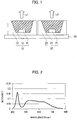
- a light emitting device includes a first light emitting unit 10 that outputs white light L1 having a first chromaticity C1; and a second light emitting unit 20 that outputs white light L2 having a second chromaticity C2.
- the light emitting device of FIG. 1 mixes the white light L1 from the first light emitting unit 10 and the white light L2 from the second light emitting unit 20 to output light having a predetermined chromaticity.
- the first and second light emitting units 10 and 20 are placed close to each other in a range that allows the white light L1 and white light L2 to be mixed.
- the first and second chromaticities C1 and C2 are located symmetrically with respect to the predetermined chromaticity (described later in detail) .
- the difference between each of the first and second chromaticities C1 and C2 and the predetermined chromaticity is not greater than 0.04.
- the first and second chromaticities C1 and C2 are described as chromaticity points. Actually, each of the first and second light emitting units 10 and 20 are manufactured so as to fall within about a 4-step MacAdam ellipse around the respective chromaticities and are combined so as to fall within about a 3-step MacAdam ellipse.
- the differences between the predetermined chromaticity and the first and second chromaticities C1 and C2 indicate lengths between the position of the predetermined chromaticity and the positions of the first and second chromaticities C1 and C2, respectively.
- the first and second chromaticities C1 and C2 are located at symmetrical positions with respect to the predetermined chromaticity.
- the lengths between the predetermined position and the first and second chromaticities C1 and C2 are determined depending on the brightness of the white light L1 and white light L2, respectively.
- the first light emitting unit 10 includes: a first blue light emitting element 11 that emits first emission light; and a first phosphor layer 12 that is excited with the first emission light to emit first excitation light.
- the peak wavelength in the emission spectrum of the first emission light is set to a first wavelength.
- the peak wavelength refers to a wavelength at which the intensity is maximized in the emission spectrum.
- the first light emitting unit 10 outputs the white light L1 having the first chromaticity C1, as a mixture of the first emission light and first excitation light.
- the first phosphor layer 12 includes phosphors, such as green and red phosphors. The components and composition of the phosphors are determined so that the first light emitting unit 10 outputs the white light L1 having the first chromaticity C1.
- the second light emitting unit 20 includes: a second blue light emitting element 21 that emits second emission light; and a second phosphor layer 22 that is excited with the second emission light to emit second excitation light.
- the peak wavelength in the emission spectrum of the second emission light is set to a second wavelength.
- the second light emitting unit 20 outputs the white light L2 having the second chromaticity C2, as a mixture of the second emission light and second excitation light.
- the second phosphor layer 22 includes phosphors. The components and composition of the phosphors are determined so that the second light emitting unit 20 outputs the white light L2 having the second chromaticity C2. Normally, the first and second phosphor layers 12 and 22 are different in components and composition of the contained phosphors.
- the first and second blue light emitting elements 11 and 21 are different in peak wavelength in the emission spectra. Specifically, the first wavelength, as the peak wavelength of the emission light from the first blue light emitting element 11, is shorter than the second wavelength, as the peak wavelength of the emission light from the second blue light emitting element 21. As described later, the difference between the first and second wavelengths is preferably 20 to 40 nm. In the following description, the first and second blue light emitting elements 11 and 21 are collectively referred to as blue light emitting elements.
- the blue light emitting elements are blue LEDs, for example.
- the first light emitting unit 10 has a structure in which a first package 13 includes a recessed portion and the first blue light emitting element 11 is placed on the bottom of the recessed portion.
- the recessed portion of the first package 13 is filled with the first phosphor layer 12.
- the second light emitting unit 20 has the same structure as that of the first light emitting unit 10.
- a second package 23 includes a recessed portion, and the second blue light emitting element 21 is placed on the bottom of the recessed portion.
- the recessed portion of the second package 23 is filled with the second phosphor layer 22.
- the first and second phosphor layers 12 and 22 are made of silicon resin including phosphors and the like.
- the first and second light emitting units 10 and 20 are collectively referred to as light emitting units.
- the first and second packages 13 and 23 are mounted on a substrate 40.
- not-illustrated electric wires are provided in the substrate 40.
- the electric wires connect to the first and second blue light emitting elements 11 and 21.
- driving current flows, and the first and second blue light emitting elements 11 and 21 emit light.
- the first and second blue light emitting elements 11 and 21 are different in peak wavelength in the emission spectrum. According to the light emitting device illustrated in FIG. 1 , therefore, the disadvantages of blue LEDs, which have a narrow half-value width, are covered, and the color rendering index R12, which is likely to be low, can be raised. According to the light emitting device illustrated in FIG. 1 , it is possible to implement the same level of brightness as general LED lighting devices through excitation by blue LEDs.
- the chromaticity of the white light obtained by using the first blue light emitting element 11 and the chromaticity of the white light obtained by using the second blue light emitting element 21 are configured so as to be located symmetrically with respect to a desired target chromaticity in the xy chromaticity diagram.
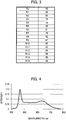
- FIG. 6 illustrates an emission spectrum S of white light obtained by mixing the two white lights with the chromaticities set as described above.
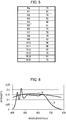
- FIG. 7 illustrates the color rendering indices thereof.
- the emission spectrum S is approximated to a spectrum B of black body radiation, which exhibits an emission spectrum of reference light of 5000 K determined by CIE.
- the color rendering indices are not less than 90 in the entire region.
- white light having a target chromaticity is obtained by mixing the two white lights with the chromaticities set symmetrically with respect to the target chromaticity.
- the color rendering indices of the obtained white light are raised in the entire region. This is because the intensities of the two blue light emitting elements having different peak wavelengths are controlled as described above.
- the amount of phosphors that use blue light is small, and the emission light from the blue light emitting element is less reduced.
- the intensity of blue light in the emission light has a high peak value.
- the amount of phosphors that use the blue light is large, and the intensity of blue light in the emission light has a low peak value.
- the intensity of blue light is controlled by changing the chromaticity in such a manner. It is therefore possible to output light of high color rendering properties in a wide range from 2000 to 10000 K.
- the intensity of the white light obtained by mixing can be increased in the entire wavelength region of blue light.
- controlling the spectral shape with the phosphor layer that is excited by the blue light emitting element is also important to provide output light of a desired chromaticity with all the color rendering indices being high. The consideration is described below.
- the first and second blue light emitting elements 11 and 21 are placed on the bottom of the recessed portion of a same package 30; and the recessed portion of the package 30 is filled with a phosphor layer 200.
- the light emitting device of the comparative example illustrated in FIG. 8 is also considered as follows.
- the first and second blue light emitting elements 11 and 21 are separately provided in different packages, and the recessed portions of the packages are filled with phosphor layers of the same components and the same composition of phosphors.
- the comparative example mixes the output lights having different fixed chromaticities that depend on only the difference in peak wavelength between the blue light emitting elements.
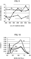
- FIG. 9 illustrates the general color rendering index Ra and the color rendering indices R9 and R12 of the output light from the light emitting device illustrated in FIG. 8 when the light emitting device is designed to have an emission spectrum of black radiation at 3000 to 6000 K.
- the color rendering index R9 is low at 3500 K. This is because the difference between the peak values of the intensities of the first and second blue light emitting elements 11 and 21 is large as illustrated in FIG. 10.
- FIG. 10 illustrates an emission spectrum Sa of the output light from the light emitting device illustrated in FIG. 8 ; an emission spectrum Sa1 of the output light obtained by using the first blue light emitting element 11; and an emission spectrum Sa2 of the output light obtained by using the second blue light emitting element 21.
- the chromaticity C11 of the output light obtained by using the first blue light emitting element 11 and the chromaticity C21 of the output light obtained by using the second blue light emitting element 21 are positioned symmetrically with respect to target chromaticity C0.
- the comparative example As described above using the comparative example, it is difficult to raise all the color rendering indices of white light that depends on only the difference between the peak wavelengths of the blue light emitting elements. Furthermore, since the chromaticities C11 and C21 are determined by the selected peak wavelengths, the target chromaticity is fixed. The comparative example therefore has low flexibility. In addition, when the blue light emitting elements vary in wavelengths, it is difficult for the light emitting device to output light having a desired chromaticity.
- the chromaticities of the output light from the first light emitting unit 10 and the output light from the second light emitting unit 20 are configured so that the output light from the light emitting device has a desired chromaticity and all the color rendering indices thereof are high.
- the chromaticities of the white lights L1 and L2 outputted from the first and second light emitting units 10 and 20 are set to the first and second chromaticities C1 and C2, respectively, so that the color rendering properties of the output light be maximized.
- the first light emitting unit 10 is formed so that the chromaticity of the white light L1 is the first chromaticity C1 while the second light emitting unit 20 is formed so that the chromaticity of the white light L2 is the second chromaticity C2.
- the method of setting the first and second chromaticities C1 and C2 is described below.
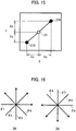
- the line connects the chromaticity C10 of the output light from the first light emitting unit 10 as the start point to the chromaticity C20 of the output light from the second light emitting unit 20 as the end point (hereinafter, referred to as a chromaticity vector) is rotated about the target chromaticity C0, that is the midpoint between the chromaticities C10 and C20. Rotating the chromaticity vector in such a manner is equivalent to changing the spectral shape while maintaining the chromaticity.
- the positions of the chromaticities C10 and C20 are determined so as to minimize the color difference corresponding to the distance between the target chromaticity C0 and each of the chromaticities C10 and C20 in the L*a*b* color space.
- the color difference ⁇ E is preferably not greater than 2.
- the color difference ⁇ E is more preferably not greater than 1.
- the color difference ⁇ E corresponding to the distance between reference light and sample light in the L*a*b* color space, is expressed by the following expression (2).
- ⁇ E ⁇ L 2 + ⁇ a 2 + ⁇ b 2 1 / 2
- ⁇ L
- ⁇ a
- ⁇ b
- differences ⁇ L, ⁇ a, and ⁇ b which are elements of the color difference ⁇ E in the L*a*b* color space for easy understanding.
- differences ⁇ W, ⁇ U, and ⁇ v which indicate the distance between coordinates (W1, U1, v1) of reference light and coordinates (W2, U2, v2) of sample light in the W*U*v* color space (JIS Z8726) .
- ⁇ W
- ⁇ U
- ⁇ v
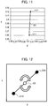
- FIG. 14 illustrates spectral distributions of the color rendering indices R1 to R15.
- the horizontal axis of FIG. 14 represents wavelength while the vertical axis represents intensity.
- the color rendering index R9, which corresponds to the red component, and the color rendering index R12, which corresponds to the blue component, are extremely important in color rendering evaluation.
- the spectral distributions of the color rendering indices R9 and R12 exhibit contrasting characteristics. It is therefore necessary to determine the condition under which the differences ⁇ W, ⁇ U, and ⁇ v, that are the elements of the color difference ⁇ E in the W*U*v* color space, are small for both the color rendering indices R9 and R12 as the chromaticity vector is rotated.
- the color difference ⁇ E depends on the chromaticity difference ⁇ C in the xy chromaticity diagram between the target chromaticity C0 and each of the chromaticities C10 and C20 and color temperature set for the output light from the light emitting device.
- the chromaticity difference ⁇ C is expressed by the following expression (3) using the difference ⁇ x in x coordinates and the difference ⁇ y in y coordinates between the target chromaticity C0 and each of the chromaticities C10 and C20 illustrated in FIG. 15 .
- ⁇ C ⁇ x 2 + ⁇ y 2 1 / 2
- the chromaticity difference ⁇ C is 0.015
- the color temperature is 3500 K.
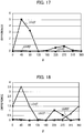
- FIG. 17 illustrates the relationship for the color rendering index R9 between the rotation angle ⁇ and squares of the differences ⁇ W, ⁇ U, and ⁇ v.
- the square of the difference ⁇ U takes a local maximum value.
- the squares of the differences ⁇ W, ⁇ U, and ⁇ v are small when the rotation angle ⁇ is 135 to 180 degrees and 315 to 360 degrees.
- FIG. 18 illustrates the relationship for the color rendering index R12 between the rotation angle ⁇ and squares of the differences ⁇ W, ⁇ U, and ⁇ v.
- the square of each of the differences ⁇ U and ⁇ v takes a local maximum value.
- the squares of the differences ⁇ W, ⁇ U, and ⁇ v are small when the rotation angle ⁇ is 135 to 180 degrees.
- FIGS. 17 and 18 show that the color difference ⁇ E is reduced for the color rendering indices R9 and R12 when the rotation angle ⁇ is 135 to 180 degrees.
- the color rendering properties are improved.
- the chromaticity C10 when the rotation angle ⁇ is 135 to 180 degrees is set as the first chromaticity C1 while the chromaticity C20 is set as the second chromaticity C2.
- FIG. 19 illustrates the relationship between the rotation angle ⁇ and the general color rendering index Ra and color rendering indices R9, R10, R11, and R12 at 5000 K.
- CNT indicates the case where the chromaticities C10 and C20 are equal to the target chromaticity C0, that is, the chromaticity difference ⁇ C is 0 (the same applies hereinafter).
- high color rendering properties are obtained in the case where the rotation angle ⁇ is 315 to 360 (0) degrees, and 135 degrees and in the case of CNT.
- the rotation angle ⁇ at which high color rendering properties are provided changes if the target chromaticity changes.
- FIG. 20 illustrates the relationship between the chromaticity difference ⁇ C and the general color rendering index Ra and color rendering indices R9 to R12 when the rotation angle ⁇ is 315 degrees.
- the color rendering properties are high when the chromaticity difference ⁇ C is in a range from 0.03 to 0.04.
- the color rendering properties are reduced, and the color rendering indices vary.
- the color rendering index R12 is particularly reduced significantly.
- the chromaticity difference ⁇ C is preferably not greater than 0.04.
- Adjustment of the chromaticity difference ⁇ C is equivalent to adjustment of the height of the peak in the emission spectrum of the output light from each light emitting unit.
- the value of the chromaticity difference ⁇ C optimal to provide high color rendering properties depends on the ratio of light outputs from the light emitting units.
- the relationship between the light output ratio and the general color rendering index Ra and color rendering indices R9 to R12 is described below.
- the light output ratio is a ratio (P2/P1) of a light output P2 from the second light emitting unit 20 to a light output P1 from the first light emitting unit 10.
- FIG. 21 illustrates the relationship between the general color rendering index Ra and the light output ratio in the case of CNT and in the cases where the chromaticity difference ⁇ C is 0.007, 0.015, 0.03, 0.04, and 0.06.
- Threshold Ta for high color rendering properties is set to 95.
- the general color rendering index Ra exceeds the threshold Ta at a light output ratio > 0.8 when the chromaticity difference ⁇ C is 0.015, 0.03, and 0.06.
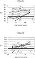
- FIGS. 22 to 25 illustrate the relationship between the color rendering indices R9, R10, R11, and R12 and light output ratio, respectively.
- Each of FIGS. 22 to 25 illustrates the relationship between the color rendering index and light output ratio in the case of CNT and in the cases where the chromaticity difference ⁇ C is 0.007, 0.015, 0.03, 0.04, and 0.06.
- Threshold Tj for high color rendering properties is set to 90.
- the color rendering index R9 exceeds the threshold Tj at a light output ratio > 0.8 in the case of CNT and in the cases where the chromaticity difference ⁇ C is 0.007, 0.015, and 0.03.
- the color rendering index R10 exceeds the threshold Tj at a light output ratio > 0.8 when the chromaticity difference ⁇ C is 0.007, 0.015, 0.03, 0.04, and 0.06.
- the color rendering indices R11 and R12 exceed the threshold Tj at a light output ratio > 0.8 for CNT and all the values of the chromaticity difference ⁇ C.
- the criterion for high color rendering properties are met at a light output ratio > 0.8 for all of the general color rendering index Ra and color rendering indices R9 to R12 when the chromaticity difference ⁇ C is 0.015 and 0.03.
- the range of the optimal value of the chromaticity difference ⁇ C changes when the target chromaticity changes.
- the inventors have found that the color difference ⁇ E can be small when the chromaticity difference ⁇ C was not greater than 0.04.
- the chromaticity difference ⁇ C of the light emitting device is preferably set to not greater than 0.04.
- the color rendering properties can be high especially when the chromaticity difference ⁇ C is not less than 0.01. Consequently, the chromaticity difference ⁇ C is more preferably not less than 0.01 and not greater than 0.04.
- the case where the chromaticities C10 and C20 are located symmetrically with respect to the target chromaticity C0 is advantageous to the case of CNT in the light of improving the color rendering properties.
- the light output ratio is set greater than 0.8 as the standard, taking into an account of the wavelength balance of the emission spectrum and the target chromaticity of the output light from the light emitting device. It is predicted that the range of light output ratio > 1 can provide the same results as those of the aforementioned consideration although the optimal value of the rotation angle ⁇ is different. The case where P1 ⁇ P2 does not exist actually.
- the peak wavelength of each blue light emitting element and the components and composition of the phosphor layer are adjusted in order that the rotation angle ⁇ and chromaticity difference ⁇ C are set optimal for high color rendering properties.
- the first light emitting unit 10 is therefore configured so that the chromaticity of the white light L1 is the first chromaticity C1.
- the second light emitting unit 20 is configured so that the chromaticity of the white light L2 is the second chromaticity C2.
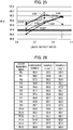
- FIG. 26 illustrates color rendering indices of output light from the comparative example illustrated in FIG. 8 and Example 1 and Example 2 of the light emitting device illustrated in FIG. 1 .
- the rotation angle ⁇ is set to 135 degrees.
- the rotation angle ⁇ is set to 180 degrees.
- all of the color rendering indices of Examples 1 and 2 are high.
- the color rendering index R9 is less than 90 in the comparative example while exceeding 90 in Examples 1 and 2.
- the color rendering indices are raised by setting the chromaticity difference ⁇ C not greater than 0.04 and setting the rotation angle ⁇ of the chromaticity vector to 135 to 180 degrees.
- the dependence of the differences ⁇ U and ⁇ v on the rotation angle ⁇ shows a local maximum value or a local minimum value when the difference between the peak wavelengths of the first and second blue light emitting elements 11 and 21 is excessively large or excessively small.
- the inventors have found that when the difference between the peak wavelengths of the first and second blue light emitting elements 11 and 21 is 20 to 40 nm, the local maximum value and local minimum value of the difference is reduced.
- the difference between the peak wavelengths of the blue light emitting elements is preferably 20 to 40 nm.
- the inventors have confirmed that the color difference ⁇ E is minimized when the peak wavelength of the first blue light emitting element 11 is in a wavelength range from 435 to 445 nm and the peak wavelength of the second blue light emitting element 21 is in a wavelength range from 455 to 470 nm.
- the peaks of the first and second blue light emitting elements 11 and 21 are preferably separated completely.
- the output lights from the first and second light emitting units 10 and 20 preferably have emission spectra with less variation in wavelength distribution.
- the kinds of the blue light emitting elements and phosphors included in the phosphor layer are properly selected.
- preferable examples of phosphors included in the first and second phosphor layers 12 and 22 are shown.
- the first phosphor layer 12 includes a green phosphor that is excited by the light emitted from the first blue light emitting element 11 to emit green light and a red phosphor that is excited by the light emitted from the first blue light emitting element 11 to emit red light.
- the components and composition of the green phosphor and red phosphor in the first phosphor layer 12 are configured so that the first light emitting unit 10 outputs the white light L1 having the first chromaticity C1.
- the second phosphor layer 22 includes a green phosphor that is excited by the light emitted from the second blue light emitting element 21 to emit green light and a red phosphor that is excited by the light emitted from the second blue light emitting element 21 to emit red light.
- the components and composition of the green phosphor and red phosphor in the second phosphor layer 22 are configured so that the second light emitting unit 20 outputs the white light L2 having the second chromaticity C2.
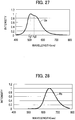
- the aforementioned green phosphors are phosphors that emit green light having an emission spectrum with a first intensity at a first wavelength and a second intensity, which is smaller than the first intensity, at a second wavelength, for example.
- a green phosphor that emits green light having an emission spectrum Gs illustrated in FIG. 27 is used in the light emitting device.
- a first wavelength ⁇ g1 corresponding to the first intensity is located in a short wavelength side of a second wavelength ⁇ g2 corresponding to the second intensity, which is smaller than the first intensity.
- the emission spectrum of green excitation light emitted from the green phosphor includes a first peak value at the first wavelength ⁇ g1 and a second peak value, which is smaller than the first peak value, at the second wavelength ⁇ g2, which is longer than the first wavelength ⁇ g1.
- the red phosphors are phosphors that emit red light and have an absorption spectrum in which green light is absorbed more at the first wavelength ⁇ g1 than at the second wavelength ⁇ g2.
- FIG. 28 illustrates an example of an emission spectrum Rs of red excitation light emitted from such a red phosphor.
- FIG. 29 illustrates an emission spectrum Bs which is a combination of emission spectra of the first blue light emitting element 11 and second blue light emitting element 21.
- wavelength ⁇ b1 indicates the peak wavelength of the first blue light emitting element 11 while wavelength ⁇ b2 indicates the peak wavelength of the second blue light emitting element 21.
- Each light emitting unit outputs, as output light, a mixture of blue light emitted from the blue light emitting element, green light emitted from the green phosphor, and red light emitted from the red phosphor.
- FIG. 30 illustrates an emission spectrum Ls of the output light of the mixture of green light, red light, and blue light, the emission spectra of which are illustrated in FIGS. 27 to 29 , respectively.
- the emission spectrum Gs illustrated in FIG. 27 is different from the emission spectrum Ls illustrated in FIG. 30 in terms of intensity in the wavelength range of green light.
- the intensity at the first wavelength ⁇ g1 is greater than the intensity at the second wavelength ⁇ g2.
- the intensity at the first wavelength ⁇ g1 is smaller than the intensity at the second wavelength ⁇ g2. This is because the red phosphor has an absorption spectrum in which green light is less absorbed at the second wavelength ⁇ g2 than at the first wavelength ⁇ g1.
- the red phosphor uses more green light at the first wavelength ⁇ g1 than at the second wavelength ⁇ g2, and the intensities at the first and second wavelengths ⁇ g1 and ⁇ g2 are inverted. This results in provision of the output light having the emission spectrum Ls that varies less in wavelength distribution and is spectrally balanced as illustrated in FIG. 30 .
- the green phosphor that emits green light having the emission spectrum Gs illustrated in FIG. 27 is an oxide-based phosphor or the like.
- the green phosphor is a scandate or a scandium oxide with Ce 3+ as the activator.
- the emission spectrum thereof includes two peak values due to transit to two separated ground levels in the crystal field.
- CaSc 2 O 4 :Ce 3+ , Ca 3 Sc 2 Si 3 O 12 :Ce 3+ , and Ca 3 (Sc, Mg) 2 Si 3 O 12 :Ce 3+ which are activated by Ce 3+
- Such a green phosphor emits green light having an emission spectrum in which the first wavelength ⁇ g1 corresponding to the first peak value is in the shorter wavelength side of the second wavelength ⁇ g2 corresponding to the second peak value, which is smaller than the first peak value.
- the red phosphor is an nitride-based phosphor having a wide bandwidth or the like.
- the red phosphor having an absorption spectrum in which absorption is greater at the first wavelength ⁇ g1 than at the second wavelength ⁇ g2 aluminum nitride phosphors activated by Eu 2+ can be used, such as CaAlSiN 3 :Eu 2+ and (Sr, Ca)AlSiN 3 :Eu 2+ .
- the chromaticity of the white light L1 outputted from the first light emitting unit 10 and the chromaticity of the white light L2 outputted from the second light emitting unit 20 are located symmetrically with respect to the target chromaticity, and the differences between the chromaticities of the white lights L1 and L2 and the target chromaticity are not greater than 0.04. This allows for the light emitting device capable of outputting white light having a predetermined chromaticity with all the color rendering indices being high.
- the rotation angle ⁇ of the chromaticity vector is set to 135 to 180 degrees and the difference between the peak wavelengths of the first and second blue light emitting elements 11 and 21 is set to 20 to 40 nm.
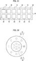
- a light emitting device includes a plurality of the first light emitting units 10 and a plurality of the second light emitting units 20, which are alternately arranged in a line.
- the light emitting device is covered with an opaque light-diffusing lamp-fitting cover, thus implementing a lamp fitting with extremely high color rendering properties.
- the first light emitting units 10 and the second light emitting units 20 are alternately arranged in the horizontal direction and vertical direction in a plan view and are covered with an opaque and light-diffusing lamp-fitting cover, thus implementing a lamp fitting with extremely high color rendering properties.
- one light emitting unit is provided with one blue light emitting element by way of example.
- one light emitting unit may be provided with plural blue light emitting elements. This can increase the luminous flux without increasing the area of the light emitting device.
- a chip on board (COB) light emitting device may be implemented using a light emitting unit of various shapes provided with plural blue light emitting elements.
- the first light emitting unit 10 each including plural first blue light emitting elements 11 is arranged around the second light emitting unit 20 including plural second blue light emitting elements 21 on a substrate.
- the first and second light emitting units 10 and 20 are arranged concentrically in a plan view.
- the first light emitting unit 10 is annular in a plan view and is located outside of the second light emitting unit 20, which is circular in a plan view.
- the plural first blue light emitting elements 11 are covered with the single first phosphor layer 12 in the first light emitting unit 10.
- the plural second blue light emitting elements 21 are covered with the single second phosphor layer 22.
- the first and second light emitting units 10 and 20 are formed by placing the first and second blue light emitting elements 11 and 21 at predetermined positions and separately applying the phosphor layers.
- the outline of the light emitting units is circular.
- the outline of the light emitting units may be rectangular or polygonal.
- the light emitted from the first blue light emitting elements 11 with a shorter peak wavelength is more likely to be absorbed by the light emitted from the second blue light emitting element with a longer peak wavelength. It is therefore preferable that the second light emitting unit 20 is located inside while the first light emitting unit 10 is located outside.
- the first light emitting units 10, which are semicircular and include a plurality of the first blue light emitting elements 11, may be located on both sides of the second light emitting unit 20, which is belt-shaped and includes a plurality of the second blue light emitting elements 21.
- the first and second light emitting units 10 and 20 can be of various shapes, and the arrangement places thereof can be combined properly.
- the light emitting device according to the second embodiment is able to output white light with a predetermined chromaticity and output high-luminance light having an emission spectrum with all the color rendering indices being raised.
- the other configurations are the same as those of the first embodiment, the redundant description is omitted.
- a lamp fitting covering the first and second light emitting units 10 and 20 may be provided on the substrate 40.
- the output light from the first light emitting unit 10 and the output light from the second light emitting unit 20 are mixed within the lamp fitting, so that white light with a predetermined chromaticity is outputted from the light emitting device.
- the green phosphor emits green light having an asymmetric emission spectrum with a major peak in the short wavelength side.
- the green phosphor that emits green light having an emission spectrum with a major peak in the long wavelength side.
- the red phosphor has an absorption spectrum with a major peak in the long wavelength side.
- the light emitting device of the invention is applicable to light emitting devices that output light by exciting a phosphor with light emitting elements.
Landscapes
- Led Device Packages (AREA)
- Non-Portable Lighting Devices Or Systems Thereof (AREA)
Applications Claiming Priority (1)
| Application Number | Priority Date | Filing Date | Title |
|---|---|---|---|
| PCT/JP2016/071394 WO2018016047A1 (ja) | 2016-07-21 | 2016-07-21 | 発光装置 |
Publications (2)
| Publication Number | Publication Date |
|---|---|
| EP3419062A1 true EP3419062A1 (de) | 2018-12-26 |
| EP3419062A4 EP3419062A4 (de) | 2019-06-12 |
Family
ID=60992404
Family Applications (1)
| Application Number | Title | Priority Date | Filing Date |
|---|---|---|---|
| EP16909522.1A Withdrawn EP3419062A4 (de) | 2016-07-21 | 2016-07-21 | Lichtemittierende vorrichtung |
Country Status (5)
| Country | Link |
|---|---|
| US (1) | US20190088831A1 (de) |
| EP (1) | EP3419062A4 (de) |
| JP (1) | JP6721048B2 (de) |
| KR (1) | KR102092573B1 (de) |
| WO (1) | WO2018016047A1 (de) |
Families Citing this family (5)
| Publication number | Priority date | Publication date | Assignee | Title |
|---|---|---|---|---|
| DE102018123010A1 (de) * | 2018-09-19 | 2020-03-19 | Osram Opto Semiconductors Gmbh | Strahlungsemittierendes bauelement |
| KR102872842B1 (ko) * | 2019-03-22 | 2025-10-22 | 삼성전자주식회사 | 백색 발광 모듈 |
| US11145793B2 (en) | 2019-05-09 | 2021-10-12 | Lumileds Llc | Light emitting diode with high melanopic spectral content |
| JP6846072B1 (ja) * | 2019-09-17 | 2021-03-24 | Zigenライティングソリューション株式会社 | 発光装置、及び照明装置 |
| EP4165344A1 (de) | 2020-06-16 | 2023-04-19 | Signify Holding B.V. | Hochintensive lichtquelle mit hohem cri |
Family Cites Families (13)
| Publication number | Priority date | Publication date | Assignee | Title |
|---|---|---|---|---|
| JP4201167B2 (ja) * | 2002-09-26 | 2008-12-24 | シチズン電子株式会社 | 白色発光装置の製造方法 |
| JP4474491B1 (ja) | 2009-08-11 | 2010-06-02 | キヤノン・コンポーネンツ株式会社 | 白色発光装置およびそれを用いたライン状照明装置 |
| JP2010218991A (ja) * | 2009-03-19 | 2010-09-30 | Hitachi Ltd | 照明装置並びにこれを用いた液晶表示装置及び映像表示装置 |
| JP2011029497A (ja) | 2009-07-28 | 2011-02-10 | Mitsubishi Chemicals Corp | 白色発光装置およびそれを用いた照明装置 |
| JP5623062B2 (ja) * | 2009-11-13 | 2014-11-12 | シャープ株式会社 | 発光装置およびその製造方法 |
| JP5501310B2 (ja) * | 2011-08-23 | 2014-05-21 | 三菱電機株式会社 | Ledモジュール及び発光装置及びledモジュールの製造方法 |
| JP2014112621A (ja) * | 2012-12-05 | 2014-06-19 | Mitsubishi Chemicals Corp | 半導体発光装置及び照明装置 |
| KR20150100664A (ko) | 2012-12-20 | 2015-09-02 | 볼보 컨스트럭션 이큅먼트 에이비 | 건설기계 액츄에이터 제어 장치 및 그의 액츄에이터 제어 방법 |
| JP2015100664A (ja) | 2013-11-28 | 2015-06-04 | 住友電気工業株式会社 | フッ素コートワイヤー |
| JP2015126160A (ja) * | 2013-12-27 | 2015-07-06 | サンケン電気株式会社 | 発光装置 |
| PL3061320T3 (pl) * | 2014-02-21 | 2017-09-29 | Philips Lighting Holding B.V. | Moduł emitujący światło, lampa, oprawa oświetleniowa oraz sposób oświetlania przedmiotu |
| JP6827265B2 (ja) * | 2015-01-05 | 2021-02-10 | シチズン電子株式会社 | Led発光装置 |
| JP2016219519A (ja) * | 2015-05-18 | 2016-12-22 | サンケン電気株式会社 | 発光装置 |
-
2016
- 2016-07-21 EP EP16909522.1A patent/EP3419062A4/de not_active Withdrawn
- 2016-07-21 KR KR1020187026938A patent/KR102092573B1/ko active Active
- 2016-07-21 WO PCT/JP2016/071394 patent/WO2018016047A1/ja not_active Ceased
- 2016-07-21 US US16/085,839 patent/US20190088831A1/en not_active Abandoned
- 2016-07-21 JP JP2018528161A patent/JP6721048B2/ja active Active
Also Published As
| Publication number | Publication date |
|---|---|
| US20190088831A1 (en) | 2019-03-21 |
| EP3419062A4 (de) | 2019-06-12 |
| JP6721048B2 (ja) | 2020-07-08 |
| JPWO2018016047A1 (ja) | 2019-01-10 |
| KR20180114164A (ko) | 2018-10-17 |
| WO2018016047A1 (ja) | 2018-01-25 |
| KR102092573B1 (ko) | 2020-03-24 |
Similar Documents
| Publication | Publication Date | Title |
|---|---|---|
| US9279549B2 (en) | Light-emitting module with wavelength converters and light-absorbing substance | |
| US9368696B1 (en) | Light emitting device | |
| JP6262211B2 (ja) | 照明装置、照明機器および表示装置 | |
| TWI422920B (zh) | Led背光模組 | |
| JP5005712B2 (ja) | 発光装置 | |
| KR102146430B1 (ko) | 발광장치 및 조명장치 | |
| EP3419062A1 (de) | Lichtemittierende vorrichtung | |
| US11320100B2 (en) | Crisp white tuning | |
| JP2015126160A (ja) | 発光装置 | |
| JP2007504644A (ja) | 色混合照明システム | |
| CN102036435A (zh) | 一种光色调制方法及光色可变的发光二极管光源模块 | |
| CN108350354A (zh) | 用于零售照明的改进的白色照明设备 | |
| JP2010147306A (ja) | 発光装置、この発光装置を用いた照明器具及び表示器具 | |
| JP2012191225A (ja) | 発光装置 | |
| TWI412784B (zh) | Led光源裝置及其出光方法 | |
| JP2014150293A (ja) | 発光装置 | |
| WO2018073219A1 (en) | Lighting device comprising a plurality of different light sources with similar off-state appearance | |
| KR102130817B1 (ko) | 고연색성 백색 발광 소자 | |
| JP7826574B2 (ja) | 発光フィラメント状デバイス | |
| US20250203726A1 (en) | Three channel chip-on-board with tunable melanopic activity at constant color point | |
| CN118804784A (zh) | 在恒定色点具有可调黑视素活性的三通道板上芯片 | |
| JP2015198119A (ja) | 発光装置 |
Legal Events
| Date | Code | Title | Description |
|---|---|---|---|
| STAA | Information on the status of an ep patent application or granted ep patent |
Free format text: STATUS: THE INTERNATIONAL PUBLICATION HAS BEEN MADE |
|
| PUAI | Public reference made under article 153(3) epc to a published international application that has entered the european phase |
Free format text: ORIGINAL CODE: 0009012 |
|
| STAA | Information on the status of an ep patent application or granted ep patent |
Free format text: STATUS: REQUEST FOR EXAMINATION WAS MADE |
|
| 17P | Request for examination filed |
Effective date: 20180920 |
|
| AK | Designated contracting states |
Kind code of ref document: A1 Designated state(s): AL AT BE BG CH CY CZ DE DK EE ES FI FR GB GR HR HU IE IS IT LI LT LU LV MC MK MT NL NO PL PT RO RS SE SI SK SM TR |
|
| AX | Request for extension of the european patent |
Extension state: BA ME |
|
| A4 | Supplementary search report drawn up and despatched |
Effective date: 20190513 |
|
| RIC1 | Information provided on ipc code assigned before grant |
Ipc: H01L 25/075 20060101ALI20190507BHEP Ipc: H01L 33/50 20100101AFI20190507BHEP |
|
| DAV | Request for validation of the european patent (deleted) | ||
| DAX | Request for extension of the european patent (deleted) | ||
| STAA | Information on the status of an ep patent application or granted ep patent |
Free format text: STATUS: THE APPLICATION IS DEEMED TO BE WITHDRAWN |
|
| 18D | Application deemed to be withdrawn |
Effective date: 20191211 |