EP3419126A1 - Dispositif de protection pour l'interconnexion de jeu de barres - Google Patents
Dispositif de protection pour l'interconnexion de jeu de barres Download PDFInfo
- Publication number
- EP3419126A1 EP3419126A1 EP17382375.8A EP17382375A EP3419126A1 EP 3419126 A1 EP3419126 A1 EP 3419126A1 EP 17382375 A EP17382375 A EP 17382375A EP 3419126 A1 EP3419126 A1 EP 3419126A1
- Authority
- EP
- European Patent Office
- Prior art keywords
- flat bar
- conductive flat
- protection
- busbar
- area
- Prior art date
- Legal status (The legal status is an assumption and is not a legal conclusion. Google has not performed a legal analysis and makes no representation as to the accuracy of the status listed.)
- Withdrawn
Links
Images


Classifications
-
- H—ELECTRICITY
- H02—GENERATION; CONVERSION OR DISTRIBUTION OF ELECTRIC POWER
- H02B—BOARDS, SUBSTATIONS OR SWITCHING ARRANGEMENTS FOR THE SUPPLY OR DISTRIBUTION OF ELECTRIC POWER
- H02B1/00—Frameworks, boards, panels, desks, casings; Details of substations or switching arrangements
- H02B1/14—Shutters or guards for preventing access to contacts
-
- H—ELECTRICITY
- H02—GENERATION; CONVERSION OR DISTRIBUTION OF ELECTRIC POWER
- H02G—INSTALLATION OF ELECTRIC CABLES OR LINES, OR OF COMBINED OPTICAL AND ELECTRIC CABLES OR LINES
- H02G5/00—Installations of bus-bars
- H02G5/04—Partially-enclosed installations, e.g. in ducts and adapted for sliding or rolling current collection
-
- H—ELECTRICITY
- H02—GENERATION; CONVERSION OR DISTRIBUTION OF ELECTRIC POWER
- H02B—BOARDS, SUBSTATIONS OR SWITCHING ARRANGEMENTS FOR THE SUPPLY OR DISTRIBUTION OF ELECTRIC POWER
- H02B1/00—Frameworks, boards, panels, desks, casings; Details of substations or switching arrangements
- H02B1/20—Bus-bar or other wiring layouts, e.g. in cubicles, in switchyards
Definitions
- the present invention relates to a protection device for electrical busbars.
- Electrical busbar protection devices generally cover the conductive flat bars of the busbars of a power box, connecting an electric distribution system with the network powering it, while at the same time allowing a certain access for making the required electrical connections.
- electric switchboards usually receive power from equipment that is not integrated in the horizontal busbar. This makes it necessary to make, at a certain point of the busbar, an interconnection between the horizontal busbar and a vertical busbar, or a busbar from the rear portion of the board, or to connect it to another horizontal busbar.
- the interconnections are made by screwing together the bars to be coupled and, in order to assure the correct electrical contact between the coupled bars, screws that have a hexagonal head, the head of which projects from the plane of the busbar, and allow providing tightening torque suitable for this attachment, are preferably used. Due to the often high circulating amperage, screws having a large size (in the order of M10 or larger) are required, or more than one screw may have to be used.
- this attachment must be provided with elastic elements such as washers which absorb contractions and expansions that will occur due to the change in temperature throughout the life of the attachment. This means that the nut-and-bolt assembly projects even more from the plane of the busbar.
- protectors known in the state of the art which allow making electrical connections in the busbar, without having to disassemble the protector usually have holes or grooves which make it possible to access said busbar therethrough.
- the front portion of the protector must be located as close as possible to the busbar itself to allow contacting the busbar with a reasonably short distance.
- This in practice, means that the protectors are usually designed for being placed a few millimeters from the busbar, so the space between the protector and the busbar does not allow housing the nuts and bolts required for interconnecting busbars, the head of which projects from the busbar.
- the state of the art lacks a protection device for electrical busbars which, with a simple and easy structure, can be installed in the electrical busbar interconnection area, and furthermore makes it easier for connecting parts of equipment (such as fuse bases) in the same space where the interconnection of busbars with the suitable nuts and bolts is made.
- a first aspect of the invention relates to a protection device for at least one conductive flat bar of an electrical busbar, with a retention area so that the device can hang from the at least one conductive flat bar, and with a protection area for covering a larger front face of the conductive flat bar, wherein the protection area comprises at least a first portion and a second portion, wherein the second portion is elevated with respect to the first portion, such that in the assembly position a cavity which allows housing nuts and bolts for connecting another conductive flat bar is defined between the conductive flat bar and the second portion.
- the retention area comprises a first retaining face and a second retaining face, arranged perpendicularly to one another, allowing the device to hang from the conductive flat bar of the electrical busbar, such that the first retaining face contacts one of the smaller faces of the conductive flat bar, and the second retaining face contacts, at at least one point, a larger rear face of the conductive flat bar.
- the first portion of the protection area comprises an access area with at least one hole, for example, in the form of a groove, wherein the at least one hole has dimensions which prevent access with a finger and in turn allow introducing a contact part for making electrical connection with the busbar. It is contemplated that the second portion is located at a greater distance from the busbar than the access area.
- the first portion and the second portion of the protection area comprise two planar segments parallel to one another.
- the present invention contemplates that the second portion is arranged, in the assembly position, facing the larger face of the conductive flat bar.
- the second portion defines a continuous cavity running between one side of the protection area and its opposite side. Therefore, the largest space possible for housing the nuts and bolts is advantageously assured.
- the cavity having an U shape and the first portion thereby being surrounded by this U-shaped cavity.
- this allows the area for housing the head of the screws to be expanded, since with this configuration they can be received not only in the area below the first portion, but can also be housed on the sides of the first portion.
- the perimeter of the second portion comprises a chamfered edge.
- One of the embodiments of the present invention contemplates elevating the second portion with respect to the inner face of the first portion, such that it allows housing one or more M10 or larger screw heads.
- the second portion is elevated at least a distance of 7 mm with respect to the inner face of the first portion. If the assembly position is used as reference, this distance can be measured either from the inner face of the first portion or from the larger face of the conductive flat bar, since both of them are touching one another at at least one point.
- the upper portion of the device of the present invention has a plurality of holes for housing a fuse base.
- these holes also serve as a guide for a person performing the installation as they make it easier to assemble the fuse bases.
- the retention area has at least one holding tab for a conductive flat bar of the electrical busbar, such that said holding tab comprises the second retaining face. Therefore, in the assembly position, the protection device is advantageously fixed to said conductive flat bar through the holding tab.
- one of the embodiments comprises a lower portion arranged such that it completes a C shape.
- the lower portion comprises coupling means for being attached to a second protection device. Therefore, an assembly consisting of several devices vertically coupled for covering busbars with several conductive flat bars can advantageously be formed. Specifically, one of the embodiments of the present invention contemplates an assembly consisting of three devices vertically coupled for protecting a three-phase busbar, although a greater or smaller number of devices can be coupled.
- the protection area further comprises side coupling means arranged on one of the ends thereof for being attached to another protection device. Therefore, an assembly consisting of several devices laterally coupled for extending the length of the protection of a conductive flat bar can advantageously be formed.
- an assembly consisting of three protectors with any combination of the features described above is contemplated for three-pole horizontal busbars powered by a vertical busbar.
- the assembly consisting of three protectors is coupled on the three-pole busbar and allows housing the nuts and bolts interconnecting each of the flat bars of said horizontal busbar with those of the vertical busbar.
- the lower portion comprises coupling means for being attached to a second identical protection device. Therefore, an assembly consisting of several devices vertically coupled for covering busbars with several conductive flat bars can advantageously be formed. Since the devices are coupled to one another, an assembly consisting of said devices is more securely fixed than a device alone.
- one of the embodiments of the present invention contemplates an assembly consisting of three unipolar devices coupled vertically for protecting a three-phase busbar, although a greater or smaller number of devices can be coupled, or a single device, being in a single part, can cover several busbars at the same time.
- the central portion of the protector i.e., its protection area further comprises side coupling means arranged on one of the edges thereof for being attached to another identical protection device. Therefore, an assembly consisting of several laterally coupled devices for extending the length of the protection of a conductive flat bar can advantageously be formed. Since the devices are coupled to one another, an assembly consisting of said devices is more securely fixed than a device alone.
- the present invention involves a series of significant advantages including, among others, the ease of installation in busbars with conductive flat bars having a rectangular section that are connected by means of nuts and bolts having a large size, wherein the heads of the screws have a considerable dimension, such that they prevent placing standard protectors. Furthermore, once the protector of the present invention is installed, it is not necessary to remove it for the connection of electric equipment, which can be safely connected, since the interconnection area is protected at all times.
- the interconnection area of busbars is thereby used for connecting fuse bases, for example.
- the present invention is particularly advantageous for busbars interconnected by means of nuts and bolts, but is likewise recommendable for use in areas of the busbar without nuts and bolts, since in the event of a possible change in the busbar configuration (for example, a new power supply connection) which requires using nuts and bolts, it would not be necessary to replace the protectors or makes modifications therein because the installation would have been ready to house the new nuts and bolts.
- the protective device of the present invention is manufactured in insulating material and has a specific length, several identical modules can be attached together to achieve a greater length and width of the protected surfaces of the busbars.
- a protective device for interconnecting electrical busbars which allows the installation thereof even in areas with nuts and bolts having a large size can be described as a practical embodiment of the invention. It is therefore prevented that said areas can be frontally touched with the fingers, but it is kept the busbar accessible by means of an area with holes, for example in the form of grooves, allowing a certain piece to access for making electrical contact.
- the protection device (1) of Figure 1 shows a preferred embodiment of the invention, which has in its upper portion (2) a housing area with holes (3) for connecting a fuse base or any other electric device without having to remove the protector completely or partially.
- this upper portion is adapted to have a retention area allowing the device to hang from the conductive flat bar (4) of the electrical busbar by one of its smaller faces (5).
- the smaller faces are the faces of the conductive flat bar having a smaller width.
- the retention area has a first retaining face and a second retaining face, arranged perpendicularly to one another, allowing the device to hang from the conductive flat bar of the electrical busbar, such that in the assembly position, with the upper portion of the protection device supported on the conductive flat bar, the first retaining face contacts one of the smaller faces (5) of the conductive flat bar, and the second retaining face, preferably implemented as holding tabs (9) hanging from the upper portion of the device, contacts, at at least one point, the larger rear face of the conductive flat bar.
- the central portion (6) of the protection device is a protection area covering the other larger face (7) (the faces with a larger width) of the conductive flat bar, since it is adapted to form a right angle with said upper portion, said protection area touching, at at least one point, the larger face of the conductive flat bar.
- the protection area has a first portion (8) and a second portion (10), wherein the second portion is elevated with respect to the first portion, such that in the assembly position, i.e., with the protector hanging from the conductive flat bar, the upper portion resting on a smaller face of a conductive flat bar of the electrical busbar and the first portion of the protection area contacting the larger face of the conductive flat bar, this second portion provides a cavity, between the conductive flat bar and the protector, said cavity having a suitable size for possibly housing the head of screws having a large size (for example, M10 screws with a hexagonal head).
- this second portion has an elevation of 7 mm with respect to the first portion, but other measurements for the adaptation thereof to the measurements of the required nuts and bolts are possible.
- the second portion represents the outermost portion of the protector, whereas the first portion, further comprising grooves to allow for electrical contact, is a recessed area with respect to the second portion. From the side, this recessed area is seen as a step since the inner face of the first portion is envisaged for being located as close as possible to, or preferably in contact with, the conductive flat bar and, in contrast, the inner face of the second portion must be located at a certain distance with respect to the conductive flat bar to allow housing one or more screw heads.
- the first portion and the second portion are configured as planes parallel to one another, which are spatially distributed such that the first portion is located in an upper half of the protection area, or the central body of the protector, and extends to the upper edge of said protection area.
- the second portion is located in the rest of the protection area, or the central body of the protector, such that it offers a continuous cavity running from side to side of the protector and extends to the lower edge thereof, which thereby allows introducing a conductive flat bar with incorporated nuts and bolts.
- the cavity corresponding to the elevation of the second portion with respect to the first portion envisaged for housing the nuts and bolts used in the busbar interconnection preferably has a constant height.
- the first portion does not extend from side to side of the protector, but is surrounded by the second portion or the elevated area, which has an U shape and a chamfered edge (11) running along the perimeter thereof, also including the edge which it shares with the first portion.
- the protection device is fixed to the conductive flat bar by means of the holding tabs (9) that hang from the upper portion of the protection device.
- the first retaining face of the device can rest on the smaller face of said flat bar, so the rest of the body is hanging down. Therefore, the assembly of the protection device on the conductive flat bar is performed by simply hanging said protection device from the conductive flat bar, such that the flat bar is inserted into the space defined between the holding tabs and the inner face of the first portion of the protection area of the protector.
- Said tabs have an retaining face parallel to the protection area of the protector, such that there is defined an area for housing the conductive flat bar which, once inserted in said area, is trapped between the holding tab and the inner face of the first portion of the protection area, so the protector can be retained on the conductive flat bar more securely.
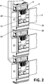
- Figure 2 depicts one of the embodiments of the invention contemplating the installation thereof in assemblies of three, for a three-pole system, in which the horizontal busbar receives power supply from a vertical busbar from the rear portion of the electric switchboard.
- the protection devices of the present invention preferably have a lower portion (12), arranged in a plane parallel to the upper portion, causing the device to have a C shape.
- This lower portion has assembling means (13) which allow, by means of a simple set of recesses, assembling the lower portion of a device with the upper portion of another device by way of tongue-and-groove joint.
- the protection device of the busbar interconnection areas of the present invention consists of an individual module that can be coupled to one of the conductive flat bars of a busbar, but these areas with nuts and bolts can sometimes exceed the width of an individual module, so installation having two or more modules is resorted to for covering a greater width (according to one of the embodiments, a single device covers a width of 100 mm, although other measurements are also indeed possible).
- Figure 3 depicts a multiple protection device installation according to the present invention where, in addition to the vertical assembly described in Figure 2 , the possibility of a horizontal assembly is also shown. Therefore, the entire front portion of the busbar can be covered and any accidental contact can be completely prevented.
- the lateral installation benefits from quick coupling means (14) by way of tongue-and-groove joint or fastening, arranged on the side edges of the central portion of the device so that it can be longitudinally attached to other contiguous identical device.
- the length of protection can therefore be increased as much as desired.
- the protective device of the present invention can be installed both in simple conductive flat bars, without any nuts and bolts or connection, and in areas with nuts and bolts and interconnection of the conductive flat bars, maintaining in all scenarios all its advantages and qualities for protecting against human contact, housing fuse bases or making electrical contact easier, among others.
Landscapes
- Engineering & Computer Science (AREA)
- Power Engineering (AREA)
- Patch Boards (AREA)
Priority Applications (1)
| Application Number | Priority Date | Filing Date | Title |
|---|---|---|---|
| EP17382375.8A EP3419126A1 (fr) | 2017-06-20 | 2017-06-20 | Dispositif de protection pour l'interconnexion de jeu de barres |
Applications Claiming Priority (1)
| Application Number | Priority Date | Filing Date | Title |
|---|---|---|---|
| EP17382375.8A EP3419126A1 (fr) | 2017-06-20 | 2017-06-20 | Dispositif de protection pour l'interconnexion de jeu de barres |
Publications (1)
| Publication Number | Publication Date |
|---|---|
| EP3419126A1 true EP3419126A1 (fr) | 2018-12-26 |
Family
ID=59677163
Family Applications (1)
| Application Number | Title | Priority Date | Filing Date |
|---|---|---|---|
| EP17382375.8A Withdrawn EP3419126A1 (fr) | 2017-06-20 | 2017-06-20 | Dispositif de protection pour l'interconnexion de jeu de barres |
Country Status (1)
| Country | Link |
|---|---|
| EP (1) | EP3419126A1 (fr) |
Cited By (1)
| Publication number | Priority date | Publication date | Assignee | Title |
|---|---|---|---|---|
| GB2594702A (en) * | 2020-04-15 | 2021-11-10 | Eaton Intelligent Power Ltd | Switchgear with an improved arc barrier |
Citations (5)
| Publication number | Priority date | Publication date | Assignee | Title |
|---|---|---|---|---|
| DE8221878U1 (de) * | 1982-08-02 | 1982-09-30 | Jean Müller GmbH Elektrotechnische Fabrik, 6228 Eltville | Elektrisch isolierendes Abdeckungselement zum Aufsetzen auf elektrische Leiter |
| DE3601988A1 (de) * | 1986-01-23 | 1987-07-30 | Loh Kg Rittal Werk | Vorrichtung zum abdecken von auf sammelschienen befestigten elektrischen geraeten |
| DE8714583U1 (de) * | 1987-11-02 | 1988-01-14 | Siemens AG, 1000 Berlin und 8000 München | Abdeckung für ein Sammelschienensystem |
| US20150111426A1 (en) * | 2013-10-18 | 2015-04-23 | Woehner Gmbh & Co. Kg Elektrotechnische Systeme | Contact protection system for power busbars |
| US20170098929A1 (en) * | 2015-10-02 | 2017-04-06 | Rockwell Automation Technologies, Inc. | System for Isolating Power Conductors Using Molded Assemblies |
-
2017
- 2017-06-20 EP EP17382375.8A patent/EP3419126A1/fr not_active Withdrawn
Patent Citations (5)
| Publication number | Priority date | Publication date | Assignee | Title |
|---|---|---|---|---|
| DE8221878U1 (de) * | 1982-08-02 | 1982-09-30 | Jean Müller GmbH Elektrotechnische Fabrik, 6228 Eltville | Elektrisch isolierendes Abdeckungselement zum Aufsetzen auf elektrische Leiter |
| DE3601988A1 (de) * | 1986-01-23 | 1987-07-30 | Loh Kg Rittal Werk | Vorrichtung zum abdecken von auf sammelschienen befestigten elektrischen geraeten |
| DE8714583U1 (de) * | 1987-11-02 | 1988-01-14 | Siemens AG, 1000 Berlin und 8000 München | Abdeckung für ein Sammelschienensystem |
| US20150111426A1 (en) * | 2013-10-18 | 2015-04-23 | Woehner Gmbh & Co. Kg Elektrotechnische Systeme | Contact protection system for power busbars |
| US20170098929A1 (en) * | 2015-10-02 | 2017-04-06 | Rockwell Automation Technologies, Inc. | System for Isolating Power Conductors Using Molded Assemblies |
Cited By (1)
| Publication number | Priority date | Publication date | Assignee | Title |
|---|---|---|---|---|
| GB2594702A (en) * | 2020-04-15 | 2021-11-10 | Eaton Intelligent Power Ltd | Switchgear with an improved arc barrier |
Similar Documents
| Publication | Publication Date | Title |
|---|---|---|
| EP2181487B1 (fr) | Tableau de commande | |
| KR100988056B1 (ko) | 규격 부스바 연결 구조 | |
| BR102014025869B1 (pt) | Sistema de proteção de contato para várias barras condutoras de energia | |
| CN107851923B (zh) | 能够防御外物损坏的可连接多根缆线的电连接装置 | |
| US9673602B2 (en) | System for isolating power conductors using cover assemblies | |
| US7859857B2 (en) | Grounding apparatus | |
| US9667051B2 (en) | Power terminal enclosure for power conductors | |
| EP3419126A1 (fr) | Dispositif de protection pour l'interconnexion de jeu de barres | |
| KR102246825B1 (ko) | 접속클립 및 이를 구비하는 mcc | |
| KR102030317B1 (ko) | 완철용 피뢰기 고정 장치 | |
| US20170033523A1 (en) | Hybrid neutral plug on bar with distributed pitch | |
| ES2882710T3 (es) | Dispositivo de distribución de corriente, en particular en un armario o panel eléctrico | |
| US9293897B2 (en) | Panelboard and electrical power distribution system | |
| KR20210074031A (ko) | 분전반 | |
| KR20190004404A (ko) | 버스바를 구비한 분전반 | |
| WO2015152913A1 (fr) | Support de masse pour sortie d'une unité de distribution de puissance de bâti et procédé correspondant | |
| KR100982332B1 (ko) | 부스 덕트의 너트 이탈방지장치 | |
| EP3419125A1 (fr) | Dispositif de protection pour barres omnibus électriques | |
| KR200457174Y1 (ko) | 멀티 콘센트용 접지단자 | |
| KR20160002644U (ko) | 분전반 | |
| US9368945B1 (en) | Isolated bolt-on circuit breaker system for an energized panelboard | |
| KR20050041387A (ko) | 전선 보호구 | |
| KR20130004254U (ko) | 저압 배전반용 버스바 조립 구조 | |
| KR102350376B1 (ko) | 분전반 | |
| KR200349445Y1 (ko) | 접지 부스바 |
Legal Events
| Date | Code | Title | Description |
|---|---|---|---|
| PUAI | Public reference made under article 153(3) epc to a published international application that has entered the european phase |
Free format text: ORIGINAL CODE: 0009012 |
|
| STAA | Information on the status of an ep patent application or granted ep patent |
Free format text: STATUS: THE APPLICATION HAS BEEN PUBLISHED |
|
| AK | Designated contracting states |
Kind code of ref document: A1 Designated state(s): AL AT BE BG CH CY CZ DE DK EE ES FI FR GB GR HR HU IE IS IT LI LT LU LV MC MK MT NL NO PL PT RO RS SE SI SK SM TR |
|
| AX | Request for extension of the european patent |
Extension state: BA ME |
|
| STAA | Information on the status of an ep patent application or granted ep patent |
Free format text: STATUS: REQUEST FOR EXAMINATION WAS MADE |
|
| RBV | Designated contracting states (corrected) |
Designated state(s): AL AT BE BG CH CY CZ DE DK EE ES FI FR GB GR HR HU IE IS IT LI LT LU LV MC MK MT NL NO PL PT RO RS SE SI SK SM TR |
|
| 17P | Request for examination filed |
Effective date: 20190626 |
|
| STAA | Information on the status of an ep patent application or granted ep patent |
Free format text: STATUS: EXAMINATION IS IN PROGRESS |
|
| 17Q | First examination report despatched |
Effective date: 20200716 |
|
| STAA | Information on the status of an ep patent application or granted ep patent |
Free format text: STATUS: THE APPLICATION IS DEEMED TO BE WITHDRAWN |
|
| 18D | Application deemed to be withdrawn |
Effective date: 20210127 |