EP3419302A1 - Système de gestion, procédé de gestion, terminal d'exploitation et appareil de commande - Google Patents
Système de gestion, procédé de gestion, terminal d'exploitation et appareil de commande Download PDFInfo
- Publication number
- EP3419302A1 EP3419302A1 EP17753270.2A EP17753270A EP3419302A1 EP 3419302 A1 EP3419302 A1 EP 3419302A1 EP 17753270 A EP17753270 A EP 17753270A EP 3419302 A1 EP3419302 A1 EP 3419302A1
- Authority
- EP
- European Patent Office
- Prior art keywords
- response
- command
- equipment
- timer
- operation terminal
- Prior art date
- Legal status (The legal status is an assumption and is not a legal conclusion. Google has not performed a legal analysis and makes no representation as to the accuracy of the status listed.)
- Granted
Links
Images



Classifications
-
- H—ELECTRICITY
- H02—GENERATION; CONVERSION OR DISTRIBUTION OF ELECTRIC POWER
- H02J—ELECTRIC POWER NETWORKS; CIRCUIT ARRANGEMENTS OR SYSTEMS FOR SUPPLYING OR DISTRIBUTING ELECTRIC POWER; SYSTEMS FOR STORING ELECTRIC ENERGY
- H02J13/00—Circuit arrangements for providing remote monitoring or remote control of equipment in a power distribution network
- H02J13/13—Circuit arrangements for providing remote monitoring or remote control of equipment in a power distribution network characterised by the transmission of data to equipment in the power network
-
- G—PHYSICS
- G05—CONTROLLING; REGULATING
- G05B—CONTROL OR REGULATING SYSTEMS IN GENERAL; FUNCTIONAL ELEMENTS OF SUCH SYSTEMS; MONITORING OR TESTING ARRANGEMENTS FOR SUCH SYSTEMS OR ELEMENTS
- G05B19/00—Program-control systems
- G05B19/02—Program-control systems electric
- G05B19/04—Program control other than numerical control, i.e. in sequence controllers or logic controllers
- G05B19/042—Program control other than numerical control, i.e. in sequence controllers or logic controllers using digital processors
-
- H—ELECTRICITY
- H02—GENERATION; CONVERSION OR DISTRIBUTION OF ELECTRIC POWER
- H02J—ELECTRIC POWER NETWORKS; CIRCUIT ARRANGEMENTS OR SYSTEMS FOR SUPPLYING OR DISTRIBUTING ELECTRIC POWER; SYSTEMS FOR STORING ELECTRIC ENERGY
- H02J13/00—Circuit arrangements for providing remote monitoring or remote control of equipment in a power distribution network
-
- H—ELECTRICITY
- H02—GENERATION; CONVERSION OR DISTRIBUTION OF ELECTRIC POWER
- H02J—ELECTRIC POWER NETWORKS; CIRCUIT ARRANGEMENTS OR SYSTEMS FOR SUPPLYING OR DISTRIBUTING ELECTRIC POWER; SYSTEMS FOR STORING ELECTRIC ENERGY
- H02J13/00—Circuit arrangements for providing remote monitoring or remote control of equipment in a power distribution network
- H02J13/13—Circuit arrangements for providing remote monitoring or remote control of equipment in a power distribution network characterised by the transmission of data to equipment in the power network
- H02J13/1331—Circuit arrangements for providing remote monitoring or remote control of equipment in a power distribution network characterised by the transmission of data to equipment in the power network using wireless data transmission
-
- H—ELECTRICITY
- H04—ELECTRIC COMMUNICATION TECHNIQUE
- H04L—TRANSMISSION OF DIGITAL INFORMATION, e.g. TELEGRAPHIC COMMUNICATION
- H04L67/00—Network arrangements or protocols for supporting network services or applications
- H04L67/01—Protocols
- H04L67/12—Protocols specially adapted for proprietary or special-purpose networking environments, e.g. medical networks, sensor networks, networks in vehicles or remote metering networks
-
- H—ELECTRICITY
- H04—ELECTRIC COMMUNICATION TECHNIQUE
- H04L—TRANSMISSION OF DIGITAL INFORMATION, e.g. TELEGRAPHIC COMMUNICATION
- H04L67/00—Network arrangements or protocols for supporting network services or applications
- H04L67/50—Network services
- H04L67/75—Indicating network or usage conditions on the user display
-
- H—ELECTRICITY
- H04—ELECTRIC COMMUNICATION TECHNIQUE
- H04Q—SELECTING
- H04Q9/00—Arrangements in telecontrol or telemetry systems for selectively calling a substation from a main station, in which substation desired apparatus is selected for applying a control signal thereto or for obtaining measured values therefrom
-
- G—PHYSICS
- G05—CONTROLLING; REGULATING
- G05B—CONTROL OR REGULATING SYSTEMS IN GENERAL; FUNCTIONAL ELEMENTS OF SUCH SYSTEMS; MONITORING OR TESTING ARRANGEMENTS FOR SUCH SYSTEMS OR ELEMENTS
- G05B2219/00—Program-control systems
- G05B2219/20—Pc systems
- G05B2219/26—Pc applications
- G05B2219/2613—Household appliance in general
-
- G—PHYSICS
- G05—CONTROLLING; REGULATING
- G05B—CONTROL OR REGULATING SYSTEMS IN GENERAL; FUNCTIONAL ELEMENTS OF SUCH SYSTEMS; MONITORING OR TESTING ARRANGEMENTS FOR SUCH SYSTEMS OR ELEMENTS
- G05B2219/00—Program-control systems
- G05B2219/20—Pc systems
- G05B2219/26—Pc applications
- G05B2219/2639—Energy management, use maximum of cheap power, keep peak load low
-
- H—ELECTRICITY
- H02—GENERATION; CONVERSION OR DISTRIBUTION OF ELECTRIC POWER
- H02J—ELECTRIC POWER NETWORKS; CIRCUIT ARRANGEMENTS OR SYSTEMS FOR SUPPLYING OR DISTRIBUTING ELECTRIC POWER; SYSTEMS FOR STORING ELECTRIC ENERGY
- H02J2101/00—Supply or distribution of decentralised, dispersed or local electric power generation
- H02J2101/20—Dispersed power generation using renewable energy sources
- H02J2101/22—Solar energy
- H02J2101/24—Photovoltaics
-
- H—ELECTRICITY
- H02—GENERATION; CONVERSION OR DISTRIBUTION OF ELECTRIC POWER
- H02J—ELECTRIC POWER NETWORKS; CIRCUIT ARRANGEMENTS OR SYSTEMS FOR SUPPLYING OR DISTRIBUTING ELECTRIC POWER; SYSTEMS FOR STORING ELECTRIC ENERGY
- H02J3/00—Circuit arrangements for AC mains or AC distribution networks
- H02J3/28—Arrangements for balancing of the load in networks by storage of energy
- H02J3/32—Arrangements for balancing of the load in networks by storage of energy using batteries or super capacitors with converting means
-
- H—ELECTRICITY
- H02—GENERATION; CONVERSION OR DISTRIBUTION OF ELECTRIC POWER
- H02J—ELECTRIC POWER NETWORKS; CIRCUIT ARRANGEMENTS OR SYSTEMS FOR SUPPLYING OR DISTRIBUTING ELECTRIC POWER; SYSTEMS FOR STORING ELECTRIC ENERGY
- H02J3/00—Circuit arrangements for AC mains or AC distribution networks
- H02J3/38—Arrangements for feeding a single network from two or more generators or sources in parallel; Arrangements for feeding already energised networks from additional generators or sources in parallel
- H02J3/381—Dispersed generators
-
- Y—GENERAL TAGGING OF NEW TECHNOLOGICAL DEVELOPMENTS; GENERAL TAGGING OF CROSS-SECTIONAL TECHNOLOGIES SPANNING OVER SEVERAL SECTIONS OF THE IPC; TECHNICAL SUBJECTS COVERED BY FORMER USPC CROSS-REFERENCE ART COLLECTIONS [XRACs] AND DIGESTS
- Y02—TECHNOLOGIES OR APPLICATIONS FOR MITIGATION OR ADAPTATION AGAINST CLIMATE CHANGE
- Y02E—REDUCTION OF GREENHOUSE GAS [GHG] EMISSIONS, RELATED TO ENERGY GENERATION, TRANSMISSION OR DISTRIBUTION
- Y02E10/00—Energy generation through renewable energy sources
- Y02E10/50—Photovoltaic [PV] energy
- Y02E10/56—Power conversion systems, e.g. maximum power point trackers
-
- Y—GENERAL TAGGING OF NEW TECHNOLOGICAL DEVELOPMENTS; GENERAL TAGGING OF CROSS-SECTIONAL TECHNOLOGIES SPANNING OVER SEVERAL SECTIONS OF THE IPC; TECHNICAL SUBJECTS COVERED BY FORMER USPC CROSS-REFERENCE ART COLLECTIONS [XRACs] AND DIGESTS
- Y02—TECHNOLOGIES OR APPLICATIONS FOR MITIGATION OR ADAPTATION AGAINST CLIMATE CHANGE
- Y02E—REDUCTION OF GREENHOUSE GAS [GHG] EMISSIONS, RELATED TO ENERGY GENERATION, TRANSMISSION OR DISTRIBUTION
- Y02E60/00—Enabling technologies; Technologies with a potential or indirect contribution to GHG emissions mitigation
-
- Y—GENERAL TAGGING OF NEW TECHNOLOGICAL DEVELOPMENTS; GENERAL TAGGING OF CROSS-SECTIONAL TECHNOLOGIES SPANNING OVER SEVERAL SECTIONS OF THE IPC; TECHNICAL SUBJECTS COVERED BY FORMER USPC CROSS-REFERENCE ART COLLECTIONS [XRACs] AND DIGESTS
- Y04—INFORMATION OR COMMUNICATION TECHNOLOGIES HAVING AN IMPACT ON OTHER TECHNOLOGY AREAS
- Y04S—SYSTEMS INTEGRATING TECHNOLOGIES RELATED TO POWER NETWORK OPERATION, COMMUNICATION OR INFORMATION TECHNOLOGIES FOR IMPROVING THE ELECTRICAL POWER GENERATION, TRANSMISSION, DISTRIBUTION, MANAGEMENT OR USAGE, i.e. SMART GRIDS
- Y04S10/00—Systems supporting electrical power generation, transmission or distribution
- Y04S10/14—Energy storage units
-
- Y—GENERAL TAGGING OF NEW TECHNOLOGICAL DEVELOPMENTS; GENERAL TAGGING OF CROSS-SECTIONAL TECHNOLOGIES SPANNING OVER SEVERAL SECTIONS OF THE IPC; TECHNICAL SUBJECTS COVERED BY FORMER USPC CROSS-REFERENCE ART COLLECTIONS [XRACs] AND DIGESTS
- Y04—INFORMATION OR COMMUNICATION TECHNOLOGIES HAVING AN IMPACT ON OTHER TECHNOLOGY AREAS
- Y04S—SYSTEMS INTEGRATING TECHNOLOGIES RELATED TO POWER NETWORK OPERATION, COMMUNICATION OR INFORMATION TECHNOLOGIES FOR IMPROVING THE ELECTRICAL POWER GENERATION, TRANSMISSION, DISTRIBUTION, MANAGEMENT OR USAGE, i.e. SMART GRIDS
- Y04S40/00—Systems for electrical power generation, transmission, distribution or end-user application management characterised by the use of communication or information technologies, or communication or information technology specific aspects supporting them
- Y04S40/12—Systems for electrical power generation, transmission, distribution or end-user application management characterised by the use of communication or information technologies, or communication or information technology specific aspects supporting them characterised by data transport means between the monitoring, controlling or managing units and monitored, controlled or operated electrical equipment
-
- Y—GENERAL TAGGING OF NEW TECHNOLOGICAL DEVELOPMENTS; GENERAL TAGGING OF CROSS-SECTIONAL TECHNOLOGIES SPANNING OVER SEVERAL SECTIONS OF THE IPC; TECHNICAL SUBJECTS COVERED BY FORMER USPC CROSS-REFERENCE ART COLLECTIONS [XRACs] AND DIGESTS
- Y04—INFORMATION OR COMMUNICATION TECHNOLOGIES HAVING AN IMPACT ON OTHER TECHNOLOGY AREAS
- Y04S—SYSTEMS INTEGRATING TECHNOLOGIES RELATED TO POWER NETWORK OPERATION, COMMUNICATION OR INFORMATION TECHNOLOGIES FOR IMPROVING THE ELECTRICAL POWER GENERATION, TRANSMISSION, DISTRIBUTION, MANAGEMENT OR USAGE, i.e. SMART GRIDS
- Y04S40/00—Systems for electrical power generation, transmission, distribution or end-user application management characterised by the use of communication or information technologies, or communication or information technology specific aspects supporting them
- Y04S40/12—Systems for electrical power generation, transmission, distribution or end-user application management characterised by the use of communication or information technologies, or communication or information technology specific aspects supporting them characterised by data transport means between the monitoring, controlling or managing units and monitored, controlled or operated electrical equipment
- Y04S40/126—Systems for electrical power generation, transmission, distribution or end-user application management characterised by the use of communication or information technologies, or communication or information technology specific aspects supporting them characterised by data transport means between the monitoring, controlling or managing units and monitored, controlled or operated electrical equipment using wireless data transmission
Definitions
- the present invention relates to a management system, a management method, an operation terminal, and a control device.
- the plurality of equipments are, for example, household electrical equipments such as air conditioner or lighting machine, distributed power supplies such as solar cells, storage batteries, or fuel power generators, and the like.
- the control device is referred to as, for example, a home energy management system (HEMS), a store energy management system (SEMS), a building energy management system (BEMS), a factory energy management system (FEMS), or a cluster/community energy management system (CEMS).
- HEMS home energy management system
- SEMS store energy management system
- BEMS building energy management system
- FEMS factory energy management system
- CEMS cluster/community energy management system
- Patent Literature 1 JP 2010-128810 A
- a management system comprises an operation terminal configured to perform a remote operation of an equipment; and a control device configured to receive an access request from the operation terminal and transmit a request command to the equipment in response to the reception of the access request.
- the operation terminal comprises a user interface configured to notify a user of information specifying an expiration timing of a response waiting timer that defines a transmission interval or a reception interval of the request command.
- a management method comprises transmitting an access request from an operation terminal to a control device; transmitting a request command from the control device to an equipment in response to reception of the access request; transmitting a response command from the equipment to the control device in response to reception of the request command; and notifying a user of information specifying an expiration timing of a response waiting timer from the operation terminal.
- the response waiting timer is a timer that defines a transmission interval or a reception interval of the request command.
- An operation terminal comprises a transmitter configured to transmit an access request to a control device that controls an equipment so as to remotely operate the equipment; and a user interface configured to notify a user of information specifying an expiration timing of a response waiting timer.
- the response waiting timer is a timer that defines a transmission interval or reception intervals of a request command transmitted from the control device to the equipment in response to the access request.
- a control device comprises a first receiver configured to receive an access request from an operation terminal; a first transmitter configured to transmit a request command to an equipment in response to reception of the access request; a second receiver configured to receive, from the equipment, a response command corresponding to the request command; and a second transmitter configured to transmit, to the equipment, information used for notification of information specifying an expiration timing of a response waiting timer.
- the the response waiting timer is a timer that defines a transmission interval or a reception interval of the request command. The information specifying the expiration timing of the response waiting timer is notified to the user from the operation terminal.
- drawings are schematic and ratios of dimensions and the like may be different from actual ones. Therefore, concrete dimensions and the like should be determined with reference to the following explanation.
- drawings may include portions having different dimensional relationships or ratios.
- the power management system 1 includes a facility 100 and an external server 400.
- the facility 100 includes a router 200.
- the router 200 is connected to the external server 400 via a network 300.
- the router 200 constitutes a local area network and is connected to, for example, a PCS 130, a load 150, an EMS controller 160, an operation terminal 170, and the like.
- a solid line indicates a power line
- a dashed line indicates a signal line. It should be noted that the present invention is not limited thereto, and a signal may be transmitted through a power line.
- the facility 100 includes a solar cell 110, a storage battery 120, the PCS 130, a distribution board 140, the load 150, the EMS controller 160, and the operation terminal 170.
- the solar cell 110 is an equipment that generates power in response to light reception.
- the solar cell 110 outputs the generated DC power.
- the power generation amount of the solar cell 110 varies according to the amount of solar radiation applied to the solar cell 110.
- the storage battery 120 is an equipment that accumulates power.
- the storage battery 120 outputs the accumulated DC power.
- the PCS 130 is an example of a power conditioning system (PCS) that converts DC power into AC power.
- the PCS 130 includes a conversion device 131 and a communication device 132.
- the conversion device 131 converts DC power input from the solar cell 110 into AC power and converts DC power input from the storage battery 120 into AC power.
- the conversion device 131 converts AC power supplied from a power system 10 into DC power.
- the communication device 132 is connected to the conversion device 131, receives various messages to the conversion device 131, and transmits various messages from the conversion device 131.
- a protocol not conforming to a predetermined protocol to be described later for example, a proprietary protocol may be used.
- the conversion device 131 is connected to a main power line 10L (here, a main power line 10LA and a main power line 10LB) connected to the power system 10 via a first distribution board 140 A, and is connected to both the solar cell 110 and the storage battery 120.
- the main power line 10LA is a power line that connects the power system 10 and the first distribution board 140A
- the main power line 10LB is a power line that connects the first distribution board 140A and the second distribution board 140B.
- the distribution board 140 is connected to the main power line 10L.
- the distribution board 140 includes the first distribution board 140A and the second distribution board 140B.
- the first distribution board 140A is connected to the power system 10 via the main power line 10LA and is also connected to the solar cell 110 and the storage battery 120 via the conversion device 131.
- the first distribution board 140A controls the power output from the conversion device 131 and the power supplied from the power system 10 to flow through the main power line 10LB.
- the power flowing from the main power line 10LB is distributed to each device (here, the load 150 and the EMS controller 160) by the second distribution board 140B.
- the load 150 is an equipment that consumes the power supplied via the power line.
- the load 150 includes equipments such as a refrigerator, a lighting, an air conditioner, a television, and the like.
- the load 150 may be a single equipment or a plurality of equipments.
- the EMS controller 160 is an energy management system (EMS) that controls each equipment (for example, the solar cell 110, the storage battery 120, the PCS 130, or the load 150). Specifically, the EMS controller 160 is connected to each equipment via the router 200 and performs communication of a predetermined message conforming to a predetermined protocol with each equipment.
- EMS energy management system
- the predetermined protocol is not particularly limited, and for example, may be ECHONET Lite, SEP 2.0, KNX, or the like.
- a predetermined format is, for example, a format conforming to ECHONET Lite.
- the predetermined message is, for example, a SET command, a GET command, a response command to the SET command, a response command to the GET command, or an INF command.
- the SET command is a message for instructing setting or operation on an equipment.
- the GET command is a message for acquiring the state of the equipment.
- the response command to the SET command is a message indicating that setting or operation instructed by the SET command has been received.
- the response command to the GET command is a message including the information requested by the GET command.
- the INF command is a message for notifying the state of the PCS 130.
- the operation terminal 170 is a terminal that remotely operates each equipment (for example, the solar cell 110, the storage battery 120, the PCS 130, or the load 150) by transmitting an access request to the EMS controller 160.
- a protocol for example, a proprietary protocol
- the operation terminal 170 is, for example, a smartphone, a tablet, or a dedicated terminal.
- the operation terminal 170 is connected to the EMS controller 160 by wire or by wireless and communicates with the EMS controller 160.
- the operation terminal 170 may perform communication of a predetermined message having a predetermined format with the EMS controller 160.
- the external server 400 is a server managed by a power company or a power aggregator.
- the external server 400 transmits a power command message to the PCS 130 or the EMS controller 160.
- the power command message is a message relating to the suppression of the forward power flow amount that is the amount of power supplied from the power system 10 or the reverse power flow amount that is the amount of power supplied to the power system 10.
- the power command message relating to the reduction of the forward power flow amount may be, for example, a message to the effect that a requested amount of reduction of the power consumption amount is ⁇ % reduction, a message to the effect that a requested amount of reduction of the power consumption amount is ⁇ kwh reduction, or a message to the effect that incentives are presented according to the reduction amount.
- a message to the suppression of the reverse power flow for example, a message to the effect that the reverse power flow is reduced by ⁇ % is assumed. If the distributed power supply such as the storage battery 120 provided in the facility 100 is used for a virtual power plant (VPP), the power command message may be a message for controlling the distributed power supply.
- VPP virtual power plant
- the control device includes a communication unit 161 and a controller 162.
- the communication unit 161 includes a communication module and communicates with each equipment (for example, the solar cell 110, the storage battery 120, the PCS 130, or the load 150).
- the communication unit 161 communicates with the operation terminal 170 and the external server 400.
- the communication unit 161 is an example of a first receiver that receives the access request from the operation terminal 170.
- the communication unit 161 is an example of a first transmitter that transmits the request command to the equipment in response to reception of the access request.
- the communication unit 161 is an example of a second receiver that receives, from the equipment, the response command corresponding to the request command.
- the communication unit 161 is an example of a second transmitter that transmits, to the equipment, information (for example, timer value information to be described later) used for notification of information specifying the expiration timing of the response waiting timer.
- the request command is a command for requesting a predetermined operation to the equipment, for example, the SET command or the GET command described above.
- the response waiting timer is a timer that defines the transmission interval or the reception interval of the request command.
- the controller 162 includes a CPU and a memory and controls the EMS controller 160.
- the controller 162 manages the response waiting timer that defines the time from the timing of transmitting the request command to the timing of receiving the response command. For example, the controller 162 activates the response waiting timer in response to the transmission of the request command, and stops the response waiting timer in response to the reception of the response command to the request command.
- the controller 162 controls the communication unit 161 so as not to continuously transmit the request command during the activation of the response waiting timer. In other words, the controller 162 restricts the transmission of the next request command until the time corresponding to the timer value set in the response waiting timer has elapsed in response to the transmission of the request command, or until the response command corresponding to the request command is received.
- the operation terminal 170 includes a communication unit 171, a user interface 172, and a controller 173.
- the communication unit 171 includes a communication module and communicates with the EMS controller 160.
- the communication unit 171 is an example of a transmitter that transmits, to the EMS controller 160 for controlling the equipment, the access request, so as to remotely operate the equipment.
- the communication unit 171 transmits, to the EMS controller 160, a timer value request requesting a timer value to be set in the response waiting timer.
- the communication unit 171 receives, from the EMS controller 160, timer value information including information indicating the timer value to be set in the response waiting timer.
- the user interface 172 includes at least one of a display and a speaker and notifies various kinds of information to the user.
- the user interface 172 notifies the user of information (hereinafter referred to as expiration timing information) specifying the expiration timing of the response waiting timer.
- the controller 173 includes a CPU and a memory and controls the operation terminal 170.
- the controller 173 controls the user interface 172 to notify the expiration timing information in response to the transmission of the access request.
- the mode of notifying the expiration timing information is not particularly limited, and may be a display of the timer value (count-down type or count-up type) set in the response waiting timer, or may be a display indicating whether the next access request can be received.
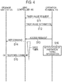
- FIG. 4 is a sequence diagram illustrating a management method according to an embodiment.
- the storage battery 120 is illustrated as the example of the equipment.
- step S11 the operation terminal 170 transmits, to the EMS controller 160, the timer value request requesting the timer value set in the response waiting timer of the EMS controller 160.
- step S12 the operation terminal 170 receives, from the EMS controller 160, timer value information including information indicating the timer value to be set in the response waiting timer of the EMS controller 160.
- step S13 the operation terminal 170 transmits the access request to the EMS controller 160 so as to remotely operate the storage battery 120.
- the access request is a request for acquiring the state of the storage battery 120.
- step S14 the EMS controller 160 transmits, to the storage battery 120, the request command corresponding to the access request.
- the request command is the above-described GET command.
- the EMS controller 160 activates the response waiting timer (first timer) in response to the transmission of the GET command.
- step S15 the EMS controller 160 receives, from the storage battery 120, the response command to the request command.
- the response command is the GET response command including information indicating the state of the storage battery 120.
- the EMS controller 160 stops the response waiting timer (first timer) in response to the reception of the GET response command. That is, the EMS controller 160 is ready to transmit the next request command.
- the response waiting timer expires in response to the reception of the GET response command.
- the response waiting timer may expire with the lapse of time corresponding to the timer value.
- step S16 the operation terminal 170 notifies the user of the expiration timing information in response to the transmission of the access request.
- the mode of notifying the expiration timing information may be a display of the timer value (count-down type or count-up type) set in the response waiting timer, or may be a display indicating whether the next access request can be received.
- the operation terminal 170 notifies the user of information specifying the expiration timing of the response waiting timer. Therefore, even if the operation terminal 170 is used to remotely operate the equipment, it is possible to reduce the possibility that the request command will be continuously transmitted from the EMS controller 160 to the equipment before the expiration of the response waiting timer, and it is possible to reduce the load of the control device.
- the operation terminal 170 acquires, from the EMS controller 160, the timer value to be set in the response waiting timer (step S11 and step S12 illustrated in Fig. 4 ).
- the process of obtaining the timer value may be omitted.
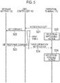
- the operation terminal 170 transmits the access request to the EMS controller 160 so as to remotely operate the storage battery 120.
- the access request is a request for acquiring the state of the storage battery 120.
- step S22 the EMS controller 160 transmits, to the storage battery 120, the request command corresponding to the access request.
- the request command is the above-described GET command.
- the EMS controller 160 activates the response waiting timer (first timer) in response to the transmission of the GET command.
- step S23 the EMS controller 160 receives, from the storage battery 120, the response command to the request command.
- the response command is the GET response command including information indicating the state of the storage battery 120.
- the EMS controller 160 stops the response waiting timer (first timer) in response to the reception of the GET response command. That is, the EMS controller 160 is ready to transmit the next request command.
- step S24 the EMS controller 160 transmits, to the operation terminal 170, the timer expiration notification indicating the expiration of the response waiting timer.
- the response waiting timer expires in response to the reception of the GET response command.
- the response waiting timer may expire with the lapse of time corresponding to the timer value.
- step S25 the operation terminal 170 notifies the information indicating that the next access request cannot be received (reception-impossible notice) in response to the transmission of the access request.
- step S26 the operation terminal 170 notifies the information indicating that the next access request can be received (reception-possible notice) in response to the reception of the timer expiration notification.
- steps S25 and 26 are an example of a process of notifying the user of information (expiration timing information) specifying the expiration timing of the response waiting timer.
- the EMS controller 160 includes a first timer and a second timer as response waiting timers.
- the second timer is an example of an operation mode resetting waiting timer applied to the operation mode setting request command requesting the setting of the operation mode of the storage battery 120.
- the first timer is an example of a timer applied to a command other than the operation mode setting request command.
- the operation mode setting request command is a SET command
- the command other than the operation mode setting request command is a GET command.
- step S31 the operation terminal 170 transmits the access request to the EMS controller 160 so as to remotely operate the storage battery 120.
- the access request is a request for setting the operation mode of the storage battery 120.
- step S32 the EMS controller 160 transmits, to the storage battery 120, the request command corresponding to the access request.
- the request command is the above-described SET command.
- the EMS controller 160 activates the first timer and activates the second timer. The reason why the first timer as well as the second timer is activated is because, even before the expiration of the second timer, the command other than the operation mode setting request command can be transmitted if the first timer has expired.
- step S33 the EMS controller 160 receives, from the storage battery 120, the response command to the request command.
- the response command is the SET response command indicating that the setting of the operation mode of the storage battery 120 has been received.
- the EMS controller 160 stops the first timer in response to the reception of the SET response command. Meanwhile, the EMS controller 160 does not stop the second timer in response to the reception of the SET response command. That is, although the EMS controller 160 is ready to transmit the command other than the operation mode setting request command, the EMS controller 160 does not become ready to transmit the operation mode setting request command.
- step S34 the storage battery 120 transmits, to the EMS controller 160, the INF command indicating the setting contents of the operation mode of the storage battery 120 in response to the setting completion of the operation mode of the storage battery 120.
- step S35 the EMS controller 160 transmits, to the operation terminal 170, the operation result for the access request received in step S31.
- step S36 the operation terminal 170 transmits the access request to the EMS controller 160 so as to remotely operate the storage battery 120.
- the access request is a request for acquiring the state of the storage battery 120.
- step S37 the EMS controller 160 transmits, to the storage battery 120, the request command corresponding to the access request.
- the request command is the above-described GET command.
- the EMS controller 160 activates the first timer in response to the transmission of the GET command.
- step S38 the EMS controller 160 receives, from the storage battery 120, the response command to the request command.
- the response command is the GET response command including information indicating the state of the storage battery 120.
- the EMS controller 160 stops the first timer in response to the reception of the GET response command. That is, the EMS controller 160 is ready to transmit the command other than the operation mode setting request command.
- step S41 the operation terminal 170 notifies both the expiration timing information about the first timer and the expiration timing information about the second timer in response to the transmission of the access request in step S31.
- step S42 the operation terminal 170 notifies the expiration timing information about the first timer in response to the transmission of the access request in step S36.
- step S42 the notification of the expiration timing information about the second timer may be continued.
- the mode of notifying the expiration timing information about the first timer and the second timer may be a display of the timer value (count-down type or count-up type) set in the response waiting timer, or may be a display indicating whether the next access request can be received.
- the response waiting timer defines the transmission interval of the request command and is provided in the EMS controller 160, but the embodiment is not limited thereto.
- the response waiting timer defines the reception interval of the request command and may be provided in the equipment.
- the timer value set in the response waiting timer may be determined according to the contents of the request command.
- the contents of the request command may be the message type (GET or SET) of the request command, may be the contents of the operation executed by the equipment, or may be the contents of the information included in the response command transmitted by the equipment.
- the request command may be executed after the expiration of the response waiting timer, or may be discarded.
- the EMS controller 160 is a device connected to the network 300, and the function of the EMS controller 160 may be provided by a cloud service via the network 300.
- the operation terminal 170 may be able to access the EMS controller 160 via a local area network provided in the facility 100, and may be able to access the EMS controller 160 via a wide area network not provided in the facility 100.
- the notification mode in the response waiting timer is not limited to the display of the timer value.
- the notification mode may display whether the reception of the access request is possible, and may display that the access request is not received. As the display for which the access request is not received, characters may be displayed, or the entire display screen may be grayed out.
Landscapes
- Engineering & Computer Science (AREA)
- Computer Networks & Wireless Communication (AREA)
- Power Engineering (AREA)
- Signal Processing (AREA)
- Automation & Control Theory (AREA)
- General Physics & Mathematics (AREA)
- Physics & Mathematics (AREA)
- Health & Medical Sciences (AREA)
- Computing Systems (AREA)
- General Health & Medical Sciences (AREA)
- Medical Informatics (AREA)
- Selective Calling Equipment (AREA)
- Remote Monitoring And Control Of Power-Distribution Networks (AREA)
- Telephonic Communication Services (AREA)
Applications Claiming Priority (2)
| Application Number | Priority Date | Filing Date | Title |
|---|---|---|---|
| JP2016029941 | 2016-02-19 | ||
| PCT/JP2017/005705 WO2017142015A1 (fr) | 2016-02-19 | 2017-02-16 | Système de gestion, procédé de gestion, terminal d'exploitation et appareil de commande |
Publications (3)
| Publication Number | Publication Date |
|---|---|
| EP3419302A1 true EP3419302A1 (fr) | 2018-12-26 |
| EP3419302A4 EP3419302A4 (fr) | 2019-10-02 |
| EP3419302B1 EP3419302B1 (fr) | 2023-11-15 |
Family
ID=59625210
Family Applications (1)
| Application Number | Title | Priority Date | Filing Date |
|---|---|---|---|
| EP17753270.2A Active EP3419302B1 (fr) | 2016-02-19 | 2017-02-16 | Système de gestion, procédé de gestion, terminal d'exploitation et appareil de commande |
Country Status (5)
| Country | Link |
|---|---|
| US (1) | US11532948B2 (fr) |
| EP (1) | EP3419302B1 (fr) |
| JP (1) | JP6802833B2 (fr) |
| CN (1) | CN108702553B (fr) |
| WO (1) | WO2017142015A1 (fr) |
Cited By (1)
| Publication number | Priority date | Publication date | Assignee | Title |
|---|---|---|---|---|
| EP4287437A1 (fr) * | 2022-06-02 | 2023-12-06 | Honeywell International Inc. | Système et appareil pour la commande de systèmes de stockage d'énergie de batterie |
Families Citing this family (3)
| Publication number | Priority date | Publication date | Assignee | Title |
|---|---|---|---|---|
| JP7052520B2 (ja) * | 2018-04-18 | 2022-04-12 | 株式会社デンソー | 端末、プログラム、およびエネルギー管理システム |
| US11388805B2 (en) | 2018-08-28 | 2022-07-12 | Signify Holding B.V. | Method for integration of plug load controllers in a lighting system |
| CN116154959B (zh) * | 2023-01-17 | 2024-01-30 | 国网江苏省电力有限公司苏州供电分公司 | 一种配电台区多融合终端边缘协同系统及方法 |
Family Cites Families (13)
| Publication number | Priority date | Publication date | Assignee | Title |
|---|---|---|---|---|
| JPH1168800A (ja) * | 1997-08-26 | 1999-03-09 | Nec Shizuoka Ltd | トラヒック制御装置 |
| JP2001285968A (ja) | 2000-03-29 | 2001-10-12 | Matsushita Electric Works Ltd | 制御システム及び制御方法 |
| US7528094B2 (en) * | 2004-10-25 | 2009-05-05 | Medtronic, Inc. | Method and apparatus for providing safe long-range telemetry with implantable medical devices |
| US20160277261A9 (en) * | 2006-12-29 | 2016-09-22 | Prodea Systems, Inc. | Multi-services application gateway and system employing the same |
| KR101387537B1 (ko) | 2007-09-20 | 2014-04-21 | 엘지전자 주식회사 | 성공적으로 수신했으나 헤더 압축 복원에 실패한 패킷의 처리 방법 |
| JP5270315B2 (ja) | 2008-11-27 | 2013-08-21 | 株式会社日立製作所 | 自動検針方法、自動検針システム、自動検針装置、およびスマートメータ |
| US10189359B2 (en) * | 2009-02-17 | 2019-01-29 | Chargepoint, Inc. | Transmitting notification messages for an electric vehicle charging network |
| CN102333304A (zh) * | 2011-11-16 | 2012-01-25 | 中兴通讯股份有限公司 | 一种远程服务器对无线终端进行管理的方法、装置和系统 |
| JP5971557B2 (ja) * | 2012-07-31 | 2016-08-17 | パナソニックIpマネジメント株式会社 | 管理装置、管理システムおよびプログラム |
| JP6042133B2 (ja) * | 2012-08-06 | 2016-12-14 | 京セラ株式会社 | 管理システム、管理方法、制御装置及び蓄電装置 |
| JP5946919B2 (ja) | 2012-09-27 | 2016-07-06 | 京セラ株式会社 | 管理システム、管理方法及び機器 |
| JP6151072B2 (ja) * | 2013-04-12 | 2017-06-21 | 京セラ株式会社 | 制御システム、制御装置、情報機器及び制御方法 |
| JP6075197B2 (ja) * | 2013-05-10 | 2017-02-08 | 富士ゼロックス株式会社 | 電力管理システム、管理装置及びプログラム |
-
2017
- 2017-02-16 WO PCT/JP2017/005705 patent/WO2017142015A1/fr not_active Ceased
- 2017-02-16 EP EP17753270.2A patent/EP3419302B1/fr active Active
- 2017-02-16 US US15/999,778 patent/US11532948B2/en active Active
- 2017-02-16 JP JP2018500190A patent/JP6802833B2/ja active Active
- 2017-02-16 CN CN201780011531.2A patent/CN108702553B/zh active Active
Cited By (2)
| Publication number | Priority date | Publication date | Assignee | Title |
|---|---|---|---|---|
| EP4287437A1 (fr) * | 2022-06-02 | 2023-12-06 | Honeywell International Inc. | Système et appareil pour la commande de systèmes de stockage d'énergie de batterie |
| AU2023202918B2 (en) * | 2022-06-02 | 2025-01-23 | Honeywell International Inc. | System and apparatus for the control of battery energy storage systems |
Also Published As
| Publication number | Publication date |
|---|---|
| CN108702553B (zh) | 2021-07-20 |
| US11532948B2 (en) | 2022-12-20 |
| EP3419302B1 (fr) | 2023-11-15 |
| EP3419302A4 (fr) | 2019-10-02 |
| US20210083508A1 (en) | 2021-03-18 |
| CN108702553A (zh) | 2018-10-23 |
| WO2017142015A1 (fr) | 2017-08-24 |
| JP6802833B2 (ja) | 2020-12-23 |
| JPWO2017142015A1 (ja) | 2018-12-27 |
Similar Documents
| Publication | Publication Date | Title |
|---|---|---|
| US10840709B2 (en) | Management method, management device, distributed power supply, and management system | |
| EP3419302B1 (fr) | Système de gestion, procédé de gestion, terminal d'exploitation et appareil de commande | |
| JP6715448B2 (ja) | 出力制御装置、電力管理装置及び電力管理方法 | |
| US10978877B2 (en) | Management system, management method, power conversion apparatus, and management apparatus | |
| CN108886644B (zh) | 管理系统、管理方法、设备以及管理装置 | |
| EP3703221A1 (fr) | Dispositif de gestion d'énergie, système de gestion d'énergie, et procédé de gestion d'énergie | |
| US10530183B2 (en) | Communication apparatus, power management apparatus, and power management method | |
| JP6328216B2 (ja) | 管理システム、管理方法、機器及び管理装置 | |
| EP3419139B1 (fr) | Système de gestion, procédé de gestion, dispositif, et appareil de commande | |
| US10754315B2 (en) | Management system and management method for transmitting a command including a code value for controlling an apparatus | |
| CN104219273A (zh) | 通用随插即用系统及通用随插即用适配器 |
Legal Events
| Date | Code | Title | Description |
|---|---|---|---|
| STAA | Information on the status of an ep patent application or granted ep patent |
Free format text: STATUS: THE INTERNATIONAL PUBLICATION HAS BEEN MADE |
|
| PUAI | Public reference made under article 153(3) epc to a published international application that has entered the european phase |
Free format text: ORIGINAL CODE: 0009012 |
|
| STAA | Information on the status of an ep patent application or granted ep patent |
Free format text: STATUS: REQUEST FOR EXAMINATION WAS MADE |
|
| 17P | Request for examination filed |
Effective date: 20180816 |
|
| AK | Designated contracting states |
Kind code of ref document: A1 Designated state(s): AL AT BE BG CH CY CZ DE DK EE ES FI FR GB GR HR HU IE IS IT LI LT LU LV MC MK MT NL NO PL PT RO RS SE SI SK SM TR |
|
| AX | Request for extension of the european patent |
Extension state: BA ME |
|
| DAV | Request for validation of the european patent (deleted) | ||
| DAX | Request for extension of the european patent (deleted) | ||
| A4 | Supplementary search report drawn up and despatched |
Effective date: 20190830 |
|
| RIC1 | Information provided on ipc code assigned before grant |
Ipc: H04Q 9/00 20060101AFI20190826BHEP Ipc: H02J 13/00 20060101ALI20190826BHEP Ipc: H02J 3/32 20060101ALN20190826BHEP |
|
| STAA | Information on the status of an ep patent application or granted ep patent |
Free format text: STATUS: EXAMINATION IS IN PROGRESS |
|
| 17Q | First examination report despatched |
Effective date: 20200330 |
|
| GRAP | Despatch of communication of intention to grant a patent |
Free format text: ORIGINAL CODE: EPIDOSNIGR1 |
|
| P01 | Opt-out of the competence of the unified patent court (upc) registered |
Effective date: 20230505 |
|
| STAA | Information on the status of an ep patent application or granted ep patent |
Free format text: STATUS: GRANT OF PATENT IS INTENDED |
|
| RIC1 | Information provided on ipc code assigned before grant |
Ipc: H02J 3/32 20060101ALN20230516BHEP Ipc: H02J 13/00 20060101ALI20230516BHEP Ipc: H04Q 9/00 20060101AFI20230516BHEP |
|
| INTG | Intention to grant announced |
Effective date: 20230615 |
|
| GRAS | Grant fee paid |
Free format text: ORIGINAL CODE: EPIDOSNIGR3 |
|
| GRAA | (expected) grant |
Free format text: ORIGINAL CODE: 0009210 |
|
| STAA | Information on the status of an ep patent application or granted ep patent |
Free format text: STATUS: THE PATENT HAS BEEN GRANTED |
|
| AK | Designated contracting states |
Kind code of ref document: B1 Designated state(s): AL AT BE BG CH CY CZ DE DK EE ES FI FR GB GR HR HU IE IS IT LI LT LU LV MC MK MT NL NO PL PT RO RS SE SI SK SM TR |
|
| RAP3 | Party data changed (applicant data changed or rights of an application transferred) |
Owner name: KYOCERA CORPORATION |
|
| REG | Reference to a national code |
Ref country code: CH Ref legal event code: EP Ref country code: GB Ref legal event code: FG4D |
|
| REG | Reference to a national code |
Ref country code: DE Ref legal event code: R096 Ref document number: 602017076516 Country of ref document: DE |
|
| REG | Reference to a national code |
Ref country code: IE Ref legal event code: FG4D |
|
| REG | Reference to a national code |
Ref country code: LT Ref legal event code: MG9D |
|
| REG | Reference to a national code |
Ref country code: NL Ref legal event code: MP Effective date: 20231115 |
|
| PG25 | Lapsed in a contracting state [announced via postgrant information from national office to epo] |
Ref country code: GR Free format text: LAPSE BECAUSE OF FAILURE TO SUBMIT A TRANSLATION OF THE DESCRIPTION OR TO PAY THE FEE WITHIN THE PRESCRIBED TIME-LIMIT Effective date: 20240216 |
|
| PG25 | Lapsed in a contracting state [announced via postgrant information from national office to epo] |
Ref country code: IS Free format text: LAPSE BECAUSE OF FAILURE TO SUBMIT A TRANSLATION OF THE DESCRIPTION OR TO PAY THE FEE WITHIN THE PRESCRIBED TIME-LIMIT Effective date: 20240315 |
|
| PG25 | Lapsed in a contracting state [announced via postgrant information from national office to epo] |
Ref country code: LT Free format text: LAPSE BECAUSE OF FAILURE TO SUBMIT A TRANSLATION OF THE DESCRIPTION OR TO PAY THE FEE WITHIN THE PRESCRIBED TIME-LIMIT Effective date: 20231115 |
|
| REG | Reference to a national code |
Ref country code: AT Ref legal event code: MK05 Ref document number: 1632855 Country of ref document: AT Kind code of ref document: T Effective date: 20231115 |
|
| PG25 | Lapsed in a contracting state [announced via postgrant information from national office to epo] |
Ref country code: NL Free format text: LAPSE BECAUSE OF FAILURE TO SUBMIT A TRANSLATION OF THE DESCRIPTION OR TO PAY THE FEE WITHIN THE PRESCRIBED TIME-LIMIT Effective date: 20231115 |
|
| PG25 | Lapsed in a contracting state [announced via postgrant information from national office to epo] |
Ref country code: AT Free format text: LAPSE BECAUSE OF FAILURE TO SUBMIT A TRANSLATION OF THE DESCRIPTION OR TO PAY THE FEE WITHIN THE PRESCRIBED TIME-LIMIT Effective date: 20231115 |
|
| PG25 | Lapsed in a contracting state [announced via postgrant information from national office to epo] |
Ref country code: ES Free format text: LAPSE BECAUSE OF FAILURE TO SUBMIT A TRANSLATION OF THE DESCRIPTION OR TO PAY THE FEE WITHIN THE PRESCRIBED TIME-LIMIT Effective date: 20231115 |
|
| PG25 | Lapsed in a contracting state [announced via postgrant information from national office to epo] |
Ref country code: NL Free format text: LAPSE BECAUSE OF FAILURE TO SUBMIT A TRANSLATION OF THE DESCRIPTION OR TO PAY THE FEE WITHIN THE PRESCRIBED TIME-LIMIT Effective date: 20231115 Ref country code: LT Free format text: LAPSE BECAUSE OF FAILURE TO SUBMIT A TRANSLATION OF THE DESCRIPTION OR TO PAY THE FEE WITHIN THE PRESCRIBED TIME-LIMIT Effective date: 20231115 Ref country code: IS Free format text: LAPSE BECAUSE OF FAILURE TO SUBMIT A TRANSLATION OF THE DESCRIPTION OR TO PAY THE FEE WITHIN THE PRESCRIBED TIME-LIMIT Effective date: 20240315 Ref country code: GR Free format text: LAPSE BECAUSE OF FAILURE TO SUBMIT A TRANSLATION OF THE DESCRIPTION OR TO PAY THE FEE WITHIN THE PRESCRIBED TIME-LIMIT Effective date: 20240216 Ref country code: ES Free format text: LAPSE BECAUSE OF FAILURE TO SUBMIT A TRANSLATION OF THE DESCRIPTION OR TO PAY THE FEE WITHIN THE PRESCRIBED TIME-LIMIT Effective date: 20231115 Ref country code: BG Free format text: LAPSE BECAUSE OF FAILURE TO SUBMIT A TRANSLATION OF THE DESCRIPTION OR TO PAY THE FEE WITHIN THE PRESCRIBED TIME-LIMIT Effective date: 20240215 Ref country code: AT Free format text: LAPSE BECAUSE OF FAILURE TO SUBMIT A TRANSLATION OF THE DESCRIPTION OR TO PAY THE FEE WITHIN THE PRESCRIBED TIME-LIMIT Effective date: 20231115 Ref country code: PT Free format text: LAPSE BECAUSE OF FAILURE TO SUBMIT A TRANSLATION OF THE DESCRIPTION OR TO PAY THE FEE WITHIN THE PRESCRIBED TIME-LIMIT Effective date: 20240315 |
|
| PG25 | Lapsed in a contracting state [announced via postgrant information from national office to epo] |
Ref country code: SE Free format text: LAPSE BECAUSE OF FAILURE TO SUBMIT A TRANSLATION OF THE DESCRIPTION OR TO PAY THE FEE WITHIN THE PRESCRIBED TIME-LIMIT Effective date: 20231115 Ref country code: RS Free format text: LAPSE BECAUSE OF FAILURE TO SUBMIT A TRANSLATION OF THE DESCRIPTION OR TO PAY THE FEE WITHIN THE PRESCRIBED TIME-LIMIT Effective date: 20231115 Ref country code: PL Free format text: LAPSE BECAUSE OF FAILURE TO SUBMIT A TRANSLATION OF THE DESCRIPTION OR TO PAY THE FEE WITHIN THE PRESCRIBED TIME-LIMIT Effective date: 20231115 Ref country code: NO Free format text: LAPSE BECAUSE OF FAILURE TO SUBMIT A TRANSLATION OF THE DESCRIPTION OR TO PAY THE FEE WITHIN THE PRESCRIBED TIME-LIMIT Effective date: 20240215 Ref country code: LV Free format text: LAPSE BECAUSE OF FAILURE TO SUBMIT A TRANSLATION OF THE DESCRIPTION OR TO PAY THE FEE WITHIN THE PRESCRIBED TIME-LIMIT Effective date: 20231115 Ref country code: HR Free format text: LAPSE BECAUSE OF FAILURE TO SUBMIT A TRANSLATION OF THE DESCRIPTION OR TO PAY THE FEE WITHIN THE PRESCRIBED TIME-LIMIT Effective date: 20231115 |
|
| PG25 | Lapsed in a contracting state [announced via postgrant information from national office to epo] |
Ref country code: DK Free format text: LAPSE BECAUSE OF FAILURE TO SUBMIT A TRANSLATION OF THE DESCRIPTION OR TO PAY THE FEE WITHIN THE PRESCRIBED TIME-LIMIT Effective date: 20231115 |
|
| PG25 | Lapsed in a contracting state [announced via postgrant information from national office to epo] |
Ref country code: CZ Free format text: LAPSE BECAUSE OF FAILURE TO SUBMIT A TRANSLATION OF THE DESCRIPTION OR TO PAY THE FEE WITHIN THE PRESCRIBED TIME-LIMIT Effective date: 20231115 |
|
| PG25 | Lapsed in a contracting state [announced via postgrant information from national office to epo] |
Ref country code: SK Free format text: LAPSE BECAUSE OF FAILURE TO SUBMIT A TRANSLATION OF THE DESCRIPTION OR TO PAY THE FEE WITHIN THE PRESCRIBED TIME-LIMIT Effective date: 20231115 |
|
| PG25 | Lapsed in a contracting state [announced via postgrant information from national office to epo] |
Ref country code: SM Free format text: LAPSE BECAUSE OF FAILURE TO SUBMIT A TRANSLATION OF THE DESCRIPTION OR TO PAY THE FEE WITHIN THE PRESCRIBED TIME-LIMIT Effective date: 20231115 Ref country code: SK Free format text: LAPSE BECAUSE OF FAILURE TO SUBMIT A TRANSLATION OF THE DESCRIPTION OR TO PAY THE FEE WITHIN THE PRESCRIBED TIME-LIMIT Effective date: 20231115 Ref country code: RO Free format text: LAPSE BECAUSE OF FAILURE TO SUBMIT A TRANSLATION OF THE DESCRIPTION OR TO PAY THE FEE WITHIN THE PRESCRIBED TIME-LIMIT Effective date: 20231115 Ref country code: IT Free format text: LAPSE BECAUSE OF FAILURE TO SUBMIT A TRANSLATION OF THE DESCRIPTION OR TO PAY THE FEE WITHIN THE PRESCRIBED TIME-LIMIT Effective date: 20231115 Ref country code: EE Free format text: LAPSE BECAUSE OF FAILURE TO SUBMIT A TRANSLATION OF THE DESCRIPTION OR TO PAY THE FEE WITHIN THE PRESCRIBED TIME-LIMIT Effective date: 20231115 Ref country code: DK Free format text: LAPSE BECAUSE OF FAILURE TO SUBMIT A TRANSLATION OF THE DESCRIPTION OR TO PAY THE FEE WITHIN THE PRESCRIBED TIME-LIMIT Effective date: 20231115 Ref country code: CZ Free format text: LAPSE BECAUSE OF FAILURE TO SUBMIT A TRANSLATION OF THE DESCRIPTION OR TO PAY THE FEE WITHIN THE PRESCRIBED TIME-LIMIT Effective date: 20231115 |
|
| REG | Reference to a national code |
Ref country code: DE Ref legal event code: R097 Ref document number: 602017076516 Country of ref document: DE |
|
| PLBE | No opposition filed within time limit |
Free format text: ORIGINAL CODE: 0009261 |
|
| STAA | Information on the status of an ep patent application or granted ep patent |
Free format text: STATUS: NO OPPOSITION FILED WITHIN TIME LIMIT |
|
| PG25 | Lapsed in a contracting state [announced via postgrant information from national office to epo] |
Ref country code: MC Free format text: LAPSE BECAUSE OF FAILURE TO SUBMIT A TRANSLATION OF THE DESCRIPTION OR TO PAY THE FEE WITHIN THE PRESCRIBED TIME-LIMIT Effective date: 20231115 |
|
| REG | Reference to a national code |
Ref country code: CH Ref legal event code: PL |
|
| PG25 | Lapsed in a contracting state [announced via postgrant information from national office to epo] |
Ref country code: LU Free format text: LAPSE BECAUSE OF NON-PAYMENT OF DUE FEES Effective date: 20240216 |
|
| PG25 | Lapsed in a contracting state [announced via postgrant information from national office to epo] |
Ref country code: CH Free format text: LAPSE BECAUSE OF NON-PAYMENT OF DUE FEES Effective date: 20240229 |
|
| 26N | No opposition filed |
Effective date: 20240819 |
|
| GBPC | Gb: european patent ceased through non-payment of renewal fee |
Effective date: 20240216 |
|
| PG25 | Lapsed in a contracting state [announced via postgrant information from national office to epo] |
Ref country code: SI Free format text: LAPSE BECAUSE OF FAILURE TO SUBMIT A TRANSLATION OF THE DESCRIPTION OR TO PAY THE FEE WITHIN THE PRESCRIBED TIME-LIMIT Effective date: 20231115 |
|
| PG25 | Lapsed in a contracting state [announced via postgrant information from national office to epo] |
Ref country code: SI Free format text: LAPSE BECAUSE OF FAILURE TO SUBMIT A TRANSLATION OF THE DESCRIPTION OR TO PAY THE FEE WITHIN THE PRESCRIBED TIME-LIMIT Effective date: 20231115 Ref country code: LU Free format text: LAPSE BECAUSE OF NON-PAYMENT OF DUE FEES Effective date: 20240216 Ref country code: CH Free format text: LAPSE BECAUSE OF NON-PAYMENT OF DUE FEES Effective date: 20240229 |
|
| REG | Reference to a national code |
Ref country code: BE Ref legal event code: MM Effective date: 20240229 |
|
| PG25 | Lapsed in a contracting state [announced via postgrant information from national office to epo] |
Ref country code: BE Free format text: LAPSE BECAUSE OF NON-PAYMENT OF DUE FEES Effective date: 20240229 |
|
| PG25 | Lapsed in a contracting state [announced via postgrant information from national office to epo] |
Ref country code: GB Free format text: LAPSE BECAUSE OF NON-PAYMENT OF DUE FEES Effective date: 20240216 |
|
| PG25 | Lapsed in a contracting state [announced via postgrant information from national office to epo] |
Ref country code: FR Free format text: LAPSE BECAUSE OF NON-PAYMENT OF DUE FEES Effective date: 20240229 |
|
| PG25 | Lapsed in a contracting state [announced via postgrant information from national office to epo] |
Ref country code: IE Free format text: LAPSE BECAUSE OF NON-PAYMENT OF DUE FEES Effective date: 20240216 |
|
| PG25 | Lapsed in a contracting state [announced via postgrant information from national office to epo] |
Ref country code: IE Free format text: LAPSE BECAUSE OF NON-PAYMENT OF DUE FEES Effective date: 20240216 Ref country code: GB Free format text: LAPSE BECAUSE OF NON-PAYMENT OF DUE FEES Effective date: 20240216 Ref country code: FR Free format text: LAPSE BECAUSE OF NON-PAYMENT OF DUE FEES Effective date: 20240229 Ref country code: BE Free format text: LAPSE BECAUSE OF NON-PAYMENT OF DUE FEES Effective date: 20240229 |
|
| PGFP | Annual fee paid to national office [announced via postgrant information from national office to epo] |
Ref country code: DE Payment date: 20241231 Year of fee payment: 9 |
|
| PG25 | Lapsed in a contracting state [announced via postgrant information from national office to epo] |
Ref country code: CY Free format text: LAPSE BECAUSE OF FAILURE TO SUBMIT A TRANSLATION OF THE DESCRIPTION OR TO PAY THE FEE WITHIN THE PRESCRIBED TIME-LIMIT; INVALID AB INITIO Effective date: 20170216 |
|
| PG25 | Lapsed in a contracting state [announced via postgrant information from national office to epo] |
Ref country code: HU Free format text: LAPSE BECAUSE OF FAILURE TO SUBMIT A TRANSLATION OF THE DESCRIPTION OR TO PAY THE FEE WITHIN THE PRESCRIBED TIME-LIMIT; INVALID AB INITIO Effective date: 20170216 |
|
| PG25 | Lapsed in a contracting state [announced via postgrant information from national office to epo] |
Ref country code: FI Free format text: LAPSE BECAUSE OF FAILURE TO SUBMIT A TRANSLATION OF THE DESCRIPTION OR TO PAY THE FEE WITHIN THE PRESCRIBED TIME-LIMIT Effective date: 20231115 |
|
| PG25 | Lapsed in a contracting state [announced via postgrant information from national office to epo] |
Ref country code: TR Free format text: LAPSE BECAUSE OF FAILURE TO SUBMIT A TRANSLATION OF THE DESCRIPTION OR TO PAY THE FEE WITHIN THE PRESCRIBED TIME-LIMIT Effective date: 20231115 |