EP3419771B2 - Compensation complete des excentricites de cylindre - Google Patents
Compensation complete des excentricites de cylindre Download PDFInfo
- Publication number
- EP3419771B2 EP3419771B2 EP17704240.5A EP17704240A EP3419771B2 EP 3419771 B2 EP3419771 B2 EP 3419771B2 EP 17704240 A EP17704240 A EP 17704240A EP 3419771 B2 EP3419771 B2 EP 3419771B2
- Authority
- EP
- European Patent Office
- Prior art keywords
- roll
- rolls
- control device
- roll stand
- eccentricity
- Prior art date
- Legal status (The legal status is an assumption and is not a legal conclusion. Google has not performed a legal analysis and makes no representation as to the accuracy of the status listed.)
- Active
Links
Images



Classifications
-
- B—PERFORMING OPERATIONS; TRANSPORTING
- B21—MECHANICAL METAL-WORKING WITHOUT ESSENTIALLY REMOVING MATERIAL; PUNCHING METAL
- B21B—ROLLING OF METAL
- B21B37/00—Control devices or methods specially adapted for metal-rolling mills or the work produced thereby
- B21B37/58—Roll-force control; Roll-gap control
- B21B37/66—Roll eccentricity compensation systems
-
- B—PERFORMING OPERATIONS; TRANSPORTING
- B21—MECHANICAL METAL-WORKING WITHOUT ESSENTIALLY REMOVING MATERIAL; PUNCHING METAL
- B21B—ROLLING OF METAL
- B21B37/00—Control devices or methods specially adapted for metal-rolling mills or the work produced thereby
- B21B37/58—Roll-force control; Roll-gap control
Definitions
- the present invention is also based on a computer program for a control device of a roll stand for rolling flat rolling stock made of metal, the computer program comprising machine code which can be processed directly by the control device, the processing of the machine code by the control device causing the control device to Rolling mill operates according to such an operating method.
- the present invention is also based on a control device for a roll stand for rolling flat metal stock, the control device being designed in such a way that it operates the roll stand in accordance with such an operating method.
- the present invention is also based on a roll stand for rolling flat metal stock, the roll stand being controlled by such a control device.
- the object of the present invention is to create possibilities by means of which an overall eccentricity occurring during the rolling of a flat rolling stock can be corrected in the simplest possible way in all possible case configurations.
- the determination and the correction should be possible, in particular, independently of which rolls of the roll stand cause the overall eccentricity and to what extent.
- an operating method of the type mentioned at the outset is designed in that during rolling pauses, during which no flat rolling stock is rolled, the upper and/or the lower set of rolls are rotated in such a way that when the next flat rolling stock is rolled, a cost function is minimized into which a total eccentricity formed by the sum of the eccentricities of the work rolls and the back-up rolls, the first time derivative of the total eccentricity and/or the second time derivative of the total eccentricity.
- the total eccentricity to be compensated for can be minimized.
- the speed at which the roll gap has to be adjusted can be minimized if only the first time derivative of the total eccentricity is included in the cost function.
- the acceleration with which the roll gap has to be adjusted can be minimized if only the second time derivative of the total eccentricity is included in the cost function.
- This procedure not only allows any eccentricity to be compensated for, regardless of whether it is caused by the work rolls or the back-up rolls. Rather, it is possible to provide only some of the rolls--namely the work rolls or the back-up rolls--with position sensors and still to determine the rotational positions of those rolls that do not have position sensors with high accuracy over long periods of rolling operation.
- the stand drives act directly on the work rolls.
- the back-up rolls are driven so that the stand drives act indirectly on the work rolls.
- the stand drives also have position transmitters which directly output position signals that are characteristic of the rotational position of the respective stand drive. Based on these signals - if necessary in Connection with translations of gears arranged between the stand drives and the driven rolls-the rotational positions of the driven rolls can be determined directly. Separate position sensors are therefore not required for these rolls to detect their rotational position.
- the rotational positions of these rollers can be determined from the rotational positions of the driven rollers in connection with the rolling condition.
- the configuration according to the invention makes it possible to avoid the accumulation of a deviation in the rotational position over several revolutions of the rollers, since a new synchronization is made possible each time the respective reference rotational position is passed by the respective roller.
- the number of initial rotational positions it will be sufficient for the number of initial rotational positions to be equal to 1, i.e. for the control device to be used for only one initial rotational position of the upper set of rollers in cooperation with a single initial rotational position of the lower set of rollers during the rolling of the rollers on one another via one of these two initial rotational positions Detection length detects the course of the change in the roll gap characteristic signal.
- This procedure can be sufficient in particular if the diameters of the back-up rolls differ from one another to a sufficient extent and the diameters of the work rolls differ from one another to a sufficient extent, or an eccentricity component is determined only for the two back-up rolls together on the one hand and the two work rolls together on the other.
- the diameters of the back-up rolls are almost identical and/or the diameters of the work rolls are almost identical and a separate compensation component is to be determined for all four rolls, it is often necessary for the number of initial rotational positions to be greater than 1.
- the number of initial rotary positions can be 2, 3, 4, . . . , for example, as required.
- the number of initial rotational positions is, for example, two
- one of the two sets of rollers is rotated relative to the other set of rollers by a predetermined rolling length after one course has been recorded.
- the rolling length can correspond, for example, to half a revolution of one of the two rollers of the respective roller set. Then the other course is recorded. So it is not important that the initial rotational positions of both sets of rollers are changed. Only twisting relative to each other is required.
- the first and second variables can be specified for the control device by a higher-level control device or by an operator.
- the first and second variables can be determined accordingly, so that they are already known when the rolls are installed in the roll stand.
- the compensation value has four eccentricity components, the sum of which is equal to the compensation value, namely one eccentricity component each for the upper back-up roll, the lower back-up roll, the upper work roll and the lower work roll.
- the rolls of the roll stand rotate counter to the direction of rotation during the rolling of the flat rolling stock rolled last. In this way, particularly in the case that not all rotational positions are detected, but some rotational positions are derived from the detected orders, errors can be minimized that would otherwise add up due to the accumulation of a deviation in the rotational position over several revolutions of the rollers.
- the procedure according to the invention already leads to excellent results. In some cases, however, it can happen that a residual eccentricity still occurs despite the correction of the set roll gap value by the determined compensation value.
- the control device detects a signal during the rolling of the flat rolling stock that is characteristic of the residual eccentricity. In this case, the control device can track the first and second variables based on the residual eccentricity.
- a computer program of the type mentioned above is designed in that the processing of the computer program by the control device causes the control device to operate the roll stand according to an operating method according to the invention.
- control device having the features of claim 10.
- the control device is designed in such a way that it operates the roll stand according to an operating method according to the invention.
- a roll stand with the features of claim 11.
- a roll stand of the type mentioned above is designed in that the roll stand is controlled by a control device according to the invention.
- a roll stand has an upper set of rolls U and a lower set of rolls L.
- the upper roll set U includes an upper work roll 1U and an upper backup roll 2U.
- the lower roll set L includes a lower work roll 1L and a lower backup roll 2L.
- a flat rolling stock 3 made of metal is rolled by means of the roll stand.
- the flat rolling stock 3 can be, in particular, a heavy plate or a metal strip.
- the metal from which the flat rolling stock 3 is made can in particular be steel. Alternatively it can be aluminium, copper, brass or another metal.
- the roll stand is controlled by a control device 4 .
- the control device 4 is designed in such a way that it operates the roll stand according to an operating method that will be explained in more detail below.
- the control device 4 is in the form of a programmable control device 4 .
- the corresponding design of the control device 4, so that it operates the roll stand according to the operating method is effected by a computer program 5 with which the control device 4 is programmed.
- the computer program 5 includes machine code 6 which can be processed directly by the control device 4 .
- the processing of the machine code 6 by the control device 4 causes the control device 4 to operate the roll stand in accordance with the corresponding operating method.
- the roll stand is operated by the control device 4 at least at times in normal operation.
- the flat rolling stock 3 is rolled in normal operation.
- the roll stand is often also occasionally operated by the control device 4 in a calibration mode. In calibration mode, no flat rolling stock is rolled by means of the roll stand 3 . It is assumed below that the roll stand is operated by the control device 4 alternatively in normal operation or in calibration operation.
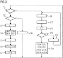
- the control device 4 therefore checks according to 3 first in a step S1 whether the roll stand is operated in normal operation. If the roll stand is operated in normal operation, the control device 4 checks in a step S2 whether a rolling stock 3 is currently being rolled. If a rolling stock 3 is currently being rolled, the control device 4 proceeds to steps S3 to S7.
- a target roll gap s* is defined in step S3.
- the control device 4 accepts a rotational position ⁇ UB, ⁇ UW, ⁇ LB, ⁇ LW of at least one roll 1U, 1L, 2U, 2L of the roll stand.
- the control device 4 determines a compensation value ⁇ dependent on the rotational position ⁇ UB, ⁇ UW, ⁇ LB, ⁇ LW of the at least one roll 1U, 1L, 2U, 2L of the roll stand.
- the determination is based on variables RUB, RUW, RLW, RLB, ⁇ 1UB, ⁇ 2UW, ⁇ 1LB, ⁇ 2LW, which for a total eccentricity of the rolls 1U, 1L, 2U, 2L of the roll stand as a function of the rotational position ⁇ UB, ⁇ UW, ⁇ LB, ⁇ LW of the at least a roll 1U, 1L, 2U, 2L of the rolling stand.
- the quantities RUB, RLB, ⁇ 1UB, ⁇ 1LB are first quantities that are characteristic of an eccentricity of the backup rolls 2U, 2L of the roll stand as a function of a rotational position ⁇ UB, ⁇ UW, ⁇ LB, ⁇ LW of at least one roll 1U, 1L, 2U, 2L of the roll stand.
- the variables RUW, RLW, ⁇ 2UW, ⁇ 2LW are second variables that are characteristic of an eccentricity of the work rolls 1U, 1L as a function of a rotational position ⁇ UB, ⁇ UW, ⁇ LB, ⁇ LW of at least one roll 1U, 1L, 2U, 2L of the roll stand .
- the meaning of the first quantities RUB, RLB, ⁇ 1UB, ⁇ 1LB and the second quantities RUW, RLW, ⁇ 2UW, ⁇ 2LW will become clear later on.
- step S6 the control device 4 corrects the set roll gap value s* by the compensation value ⁇ determined in step S4.
- step S7 the control device 4 sets a roll gap s of the roll stand in accordance with the corrected roll gap target value. As a result, the flat rolling stock 3 is rolled from an initial thickness to a final thickness by means of the roll stand in accordance with the corrected set roll gap value.
- step S7 the controller goes back to step S1.
- the sequence of steps S1 to S7 is therefore continuously executed by the control device 4 during the rolling of the flat rolled stock 3 .
- step S8 If the control device 4 operates the roll stand in normal operation, but no flat rolling stock is being rolled at the moment, the control device 4 goes from step S2 to a step S8. Other measures can be taken in step S8, which will be explained in more detail later.
- the roll stand is in calibration mode. In this case, the controller proceeds to steps S9 through S14. In calibration mode, the first and second variables RUB, RUW, RLW, RLB, ⁇ 1UB, ⁇ 2UW, ⁇ 1LB, ⁇ 2LW are determined.
- a defined initial rotational position of the upper roller set U and a defined initial rotational position of the lower roller set L of the roll stand are set.
- the two initial rotational positions can be set in such a way that in FIG 4 shown (only imaginary) points of the upper work roll 1U and the upper back-up roll 2U are directly opposite each other and in an analogous manner in FIG 4 illustrated (only imaginary) points of the lower work roll 1L and the lower back-up roll 2L are directly opposite to each other.
- the roll stand can be raised so that the upper work roll 1U and the lower work roll 1L do not touch. Thereafter, the two sets of rollers U, L are rotated independently of one another into their respective initial rotational positions.
- rollers 1U, 2U of the upper roller set U are lifted off the rollers 1L, 2L of the lower roller set L in order to be able to rotate the two roller sets U, L independently of one another into their respective initial rotational position.
- mutually independent drives 7U, 7L for the two sets of rollers U, L for example, as shown in FIG 1
- a common drive can be present, which is permanently connected, for example, to the lower set of rollers L, but to the upper set of rollers U via a releasable coupling.
- the clutch is released and the lower set of rollers L is brought into its initial position. The clutch is then closed again.
- the control device 4 controls the roller stand in step S10 in such a way that the roller gap s is closed.
- the roll gap s is closed without the flat rolling stock being in the roll gap s.
- the upper work roll 1U thus rests on the lower work roll 1L.
- step S11 the control device 4 controls the roll stand in such a way that the rolls 1U, 1L, 2U, 2L roll on one another.
- This state - that is, the rolling of the rollers 1U, 1L, 2U, 2L on each other - is maintained for a relatively large length L0.
- the length L0 is hereinafter referred to as the detection length L0.
- the detection length L0 is based on the respective initial rotational position of the roller sets U, L. In particular, it is dimensioned in such a way that all rollers 1U, 1L, 2U, 2L perform several complete revolutions.
- the control device 4 simultaneously also detects a progression of a signal F, s over the detection length L0, which is characteristic of a change in the roll gap s.
- the signal F, s is - of course - dependent on the rotational position ⁇ UB, ⁇ UW, ⁇ LB, ⁇ LW of the at least one roller 1U, 1L, 2U, 2L.
- the control device 4 can keep the roll stand within the framework of step S11 with roll gap control at a constant setting of the roll gap s and detect the associated rolling force F as a characteristic signal s,F.
- control device 4 can, conversely, operate the roll stand within the framework of step S11 in a roll-force-regulated manner with a constant roll force F and detect the resulting roll gap s as a characteristic signal s, F.
- the detected signal s, F directly reflects the total eccentricity ⁇ .
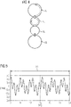
- 5 shows - purely by way of example - the change in the resulting roll gap s in the case of a roll force control over a detection length L0 of 30 m and a diameter of the work rolls 1U, 1L of approx. 1.00 m and a diameter of the backup rolls 2U, 2L with a diameter of approx. 1.65 m.
- 6 12 shows, purely by way of example, the corresponding revolutions of the work rolls 1U, 1L and the back-up rolls 2U, 2L.
- step S12 the control device 4 checks whether it has already carried out the procedure of steps S9 to S11 for all required pairs of initial rotary positions. Only when this is the case does the control device 4 go to step S14.
- step S12 the control device 4 selects the next pair of initial rotational positions. From step S13, the controller then goes back to step S9.
- the number of other pairs of initial rotary positions and the associated positions as such can be determined as required.
- the initial rotational position of the lower roll set L may be unchanged while the upper roll set U is rotated by a predetermined angle of each of the upper work roll 1U and the upper backup roll 2U, as required.
- the reverse procedure is also possible. It is also possible for both sets of rollers U, L to be rotated.
- the predetermined angle can, for example, as in FIG 4 shown in dashed lines, correspond to half a revolution of the upper backup roller 2U.
- F. 8 12 shows the respective number of revolutions of the work rolls 1U, 1L and the back-up rolls 2U, 2L.
- step S14 the control device 4 uses the recorded curves to determine the first and second variables RUB, RUW, RLW, RLB, ⁇ 1UB, ⁇ 2UW, ⁇ 1LB, ⁇ 2LW. The basis of this determination is explained in more detail below.
- a roller 8 should be perfectly round, that is, it should not have any eccentricity. In practice, however, this is not the case.
- 9 shows - greatly exaggerated - a variation of a radius r of the roller 8 as a function of the rotational position ⁇ of the roller 8 relative to a reference position.
- r0 designates the average (ideal) radius of the roll 8.
- ⁇ ri designates the proportion of the i-th disturbance.
- ⁇ i designates a phase angle of the i-th disturbance.
- Equation 2 Eight quantities are unknown in Equation 2, namely the four eccentricity amplitudes RUB, RUW, RLW, RLB and the four phase angles ⁇ 1UB, ⁇ 2UW, ⁇ 1LB, ⁇ 2LW.
- l is the distance covered on the circumference of the rollers 1U, 1L, 2U, 2L.
- the rotary positions ⁇ UB, ⁇ UW, ⁇ LB, ⁇ LW of both the back-up rolls 2U, 2L and the work rolls 1U, 1L of the roll stand are detected by means of corresponding rotary position sensors 9U, 9L.
- the detected rotational positions ⁇ UB, ⁇ UW, ⁇ LB, ⁇ LW are supplied to the control device 4 and received by the control device 4 .
- a pair of similar rolls 1U, 1L, 2U, 2L--usually the back-up rolls 2U, 2L--an additional pair of rotary encoders 9U, 9L is required for this in this case.
- the roll stand drives 7U, 7L usually have internal rotary encoders. According to the invention, their signals can be used to determine the rotational positions ⁇ UB, ⁇ UW, ⁇ LB, ⁇ LW of the driven rollers 1U, 1L, 2U, 2L.
- the rotary position ⁇ UB, ⁇ LB, ⁇ UW, ⁇ LW of the respective other roller 2U, 2L, 1U, 1L of the corresponding roller set U, L is determined by the control device 4 based on the rotary position ⁇ UB, ⁇ UW, ⁇ LB, ⁇ LW of that roller 1U, 1L, 2U, 2L of the corresponding set of rollers U, L, whose rotational position ⁇ UB, ⁇ UW, ⁇ LB, ⁇ LW is detected.
- this procedure is used both in normal operation and in calibration operation.
- the rolls 1U, 1L, 2U, 2L of the roll stand rotate counter to the direction of rotation in which the rolls 1U, 1L, 2U, 2L are rotated during the rolling of the last rolled flat rolling stock 3.
- the reels 1U, 1L, 2U, 2L are rotated backwards.
- the turning back is a possible embodiment of step S8 of 3 . Accordingly, the roll stand is operated normally at this point in time. The turning back is thus performed as part of a normal rolling pause between the rolling of two flat rolling stock 3 .
- reference signal generators 10U, 10L are assigned to the backup rollers 2U, 2L.
- the reference signal generators 10U, 10L do not detect the rotational position ⁇ UB, ⁇ LB of the support rollers 2U, 2L over the entire angular range of 360°. However, they each emit a signal (for example a pulse) when the rotational position ⁇ UB, ⁇ LB of the corresponding backup roller 2U, 2L corresponds to a predetermined reference rotational position.
- the reference signal generators 10U, 10L the passage of the reference rotary position is detected in each case during the continuous rotation of the support rollers 2U, 2L.
- the corresponding signals are of course fed to the control device 4 .
- the reverse procedure is also possible, i.e. the rotational positions ⁇ UB, ⁇ LB of the backup rolls 2U, 2L are detected, the rotational positions ⁇ UW, ⁇ LW of the work rolls 1U, 1L are derived from the rotational positions ⁇ UB, ⁇ LB of the backup rolls 2U, 2L and for the work rolls 1U, 1L each passing a reference rotational position is detected.
- the control device 4 For each roller 1U, 1L, 2U, 2L, the control device 4 thus determines, as a function of the rotary position ⁇ UB, ⁇ UW, ⁇ LB, ⁇ LW of the respective roller 1U, 1L, 2U, 2L, the associated roller 1U, 1L, 2U, 2L and adds the part eccentricities to the total eccentricity ⁇ . In normal operation, the control device 4 thus determines the compensation value ⁇ as a function of the respective rotational position ⁇ UB, ⁇ UW, ⁇ LB, ⁇ LW of both the upper and lower work roll 1U, 1L and the upper and lower backup roll 2U, 2L.
- the control device 4 In order to be able to determine the four part eccentricities mentioned, the control device 4 must also have the corresponding characteristic quantities RUB, RUW, RLW, RLB, ⁇ 1UB, ⁇ 2UW, ⁇ 1LB, ⁇ 2LW must be known. As part of the calibration operation, the control device 4 thus determines the variables RUB, ⁇ UB for the upper support roll 2U, which are characteristic of the part eccentricity thereof. In a similar manner, the two variables RUW, RLW, RLB, ⁇ 2UW, ⁇ 1LB, ⁇ 2UW, ⁇ 1LB, ⁇ 2LW.
- the radii or diameters of the support rollers 2L, 2U are generally the same size as one another. Likewise, the radii or diameters of the work rolls 1U, 1L are generally the same as one another. If it can be ensured that between two calibrations only a sufficiently small amount of slip occurs between the rolls 1U, 2U of the upper set of rolls U compared to the rolls 1U, 1L of the lower set of rolls L, the partial eccentricities caused by the support rolls 2U, 2L can and can be combined also, the part eccentricities caused by the work rolls 1U, 1L are summarized. In this case, too, the total eccentricity is the sum of the partial eccentricities of the back-up rolls 2U, 2L and the work rolls 1U, 1L.
- the sum has only two summands, namely one each for the partial eccentricity caused by the backup rolls 2U, 2L and for the partial eccentricity caused by the work rolls 1U, 1L.
- the control device 4 determines a partial eccentricity for the work rolls 1U, 1L as a function of the rotational position ⁇ UW, ⁇ LW of one of the work rolls 1U, 1L and a partial eccentricity for the Backup rolls 2U, 2L. In this case, it also adds the two partial eccentricities to the total eccentricity ⁇ .
- the control device 4 determines the compensation value ⁇ in normal operation as a function of the rotational position ⁇ UB, ⁇ UW, ⁇ LB, ⁇ LW of both the work rolls 1U, 1L and the back-up rolls 2U, 2L.
- the control device 4 determines uniform values for the two support rollers 2U, 2L which are characteristic of their partial eccentricity, for example an eccentricity amplitude and a phase position.
- the control device 4 determines uniform variables for the two work rolls 1U, 1L in the calibration mode, which are characteristic of their partial eccentricity, for example an eccentricity amplitude and a phase position.
- Steps S21 to S23 are executed. Steps S21 to S23 are an embodiment of step S8 of FIG FIG 1 .
- control device 4 determines a cost function K. Weighted with respective weighting factors ⁇ 0 to ⁇ 2, the total eccentricity ⁇ , the first time derivative of the total eccentricity ⁇ and/or the second time derivative of the total eccentricity ⁇ can be included in the cost function K. It is possible that all three weighting factors ⁇ 0 to a2 are different from 0. Alternatively, it is possible that only two of the weighting factors ⁇ 0 to ⁇ 2 are different from 0. However, at least one of the three weighting factors ⁇ 0 to ⁇ 2 must be different from 0.
- the weighting factors ⁇ 0 to a2 can be permanently specified for the control device 4 or can be defined by a user as part of a parameterization.
- the control device 4 continues to determine a minimum of the cost function K over a rolled length L1 in step S22. So it forms the integral ⁇ O L 1 ⁇ K ⁇ dl and minimizes the integral by varying rotational positions ⁇ UB, ⁇ UW, ⁇ LB, ⁇ LW of the rolls 1U, 1L, 2U, 2L at which rolling of the next flat rolled stock 3 is started.
- the rolled length L1 is—relative to the lateral surfaces of the rolls 1U, 1L, 2U, 2L—that length over which the rolls 1U, 1L, 2U, 2L roll this flat rolling stock 3.
- step S23 the control device 4 then sets the rotational positions ⁇ UB, ⁇ UW, ⁇ LB, ⁇ LW of the rollers 1U, 1L, 2U, 2L accordingly.
- the control device 4 thus rotates the upper and/or the lower set of rolls U, L in such a way that the cost function K is minimized when the next flat rolling stock 3 is rolled.
- the roll stand is closed as part of step S23.
- the two sets of rollers U, L can only be rotated together.
- the roll stand can be opened.
- the two sets of rollers U, L can be rotated independently of each other.
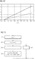
- 11 shows a comparison between a measured (M) eccentricity ⁇ and an associated, modeled (C) eccentricity ⁇ , i.e. an eccentricity ⁇ , which is determined using the eccentricity amplitudes RUB, RUW, RLW, RLB and phase angles ⁇ 1UB, ⁇ 2UW, ⁇ 1LB, ⁇ 2LW
- the eccentricity amplitudes RUB, RUW, RLW, RLB and phase angles ⁇ 1UB, ⁇ 2UW, ⁇ 1LB, ⁇ 2LW were determined using the measured course of the eccentricity ⁇ .
- 12 shows the associated history of the revolutions of the rollers 1U, 1L, 2U, 2L.
- the eccentricities of the rollers 1U, 1L, 2U, 2L are completely compensated for by applying the compensation signal ⁇ . Due to thermal effects, wear, etc., it can happen, however, that despite the correction of the roll gap setpoint value s* by the compensation value ⁇ determined, there is only incomplete compensation so that a residual eccentricity ⁇ r remains. It is therefore possible that the control device 4 as shown in 13 during the rolling of the flat rolling stock 3, a signal F, Z, which is characteristic of the residual eccentricity ⁇ r, is detected in a step S31.
- This signal F, Z can be, for example, the rolling force F or a tension Z prevailing in front of or behind the rolling stand in the flat rolling stock 3 .
- a thickness of the flat rolling stock 3 measured on the outlet side of the roll stand can also be used as a signal.
- the control device 4 can compensate for the residual eccentricity ⁇ r in a step S32 currently—that is, during the rolling of the flat rolling stock 3 .
- the control device 4 corrects the set roll gap value s* not only by the compensation value ⁇ , but also by the residual eccentricity ⁇ r.
- the control device 4 can also track the first and second variables RUB, RUW, RLW, RLB, ⁇ 1UB, ⁇ 2UW, ⁇ 1LB, ⁇ 2LW in a step S33.
- control device 4 determines the first and second variables RUB, RLB, ⁇ 1UB, ⁇ 1LB, RUW, RLW, ⁇ 2UW, ⁇ 2LW completely based on the residual eccentricity ⁇ r that the amplitudes RUB, RLB, RUW, RLW of the individual eccentricities so initially have the value 0.
- the phase angles ⁇ 1UB, ⁇ 1LB, ⁇ 2UW, ⁇ 2LW are initially irrelevant in this case.
- eccentricity amplitudes RUB, RUW, RLW, RLB and phase angles ⁇ 1UB, ⁇ 2UW, ⁇ 1LB, ⁇ 2LW were used above as the first and second variables RUB, RUW, RLW, RLB, ⁇ 1UB, ⁇ 2UW, ⁇ 1LB, ⁇ 2LW.
- the eccentricities of the rollers 1U, 1L, 2U, 2L could also be described by amplitudes AUB, BUB, ALB, BLB, AUW, BUW, ALW, BLW of corresponding sine and cosine functions. Equation 5 below could therefore also be used instead of Equation 2.
- the present invention has many advantages.
- all roll eccentricities can be determined and compensated. This applies regardless of whether the eccentricities are caused by work rolls 1U, 1L or back-up rolls 2U, 2L.
- the roll eccentricities can be determined faster and more accurately.
- the roll eccentricities can also be determined when the roll stand has further rolls in addition to the work rolls 1U, 1L and the back-up rolls 2U, 2L, in particular intermediate rolls arranged between the work rolls 1U, 1L and the back-up rolls 2U, 2L.
Landscapes
- Engineering & Computer Science (AREA)
- Mechanical Engineering (AREA)
- Control Of Metal Rolling (AREA)
Claims (11)
- Procédé d'exploitation pour une cage de laminoir destinée au laminage d'un produit plat de laminage (3) en métal ;- dans lequel la cage de laminoir présente une batterie de cylindres supérieurs (U) et une batterie de cylindres inférieurs (L) ;- dans lequel la batterie de cylindres supérieurs (U) présente au moins un cylindre de travail supérieur (1U) et un cylindre de soutien supérieur (2U) et la batterie de cylindres inférieurs (L) présente au moins un cylindre de travail inférieur (1L) et un cylindre de soutien inférieur (2L) ;- dans lequel la cage de laminoir est exploitée au moins par moments conformément à une exploitation normale ;- dans lequel la cage de laminoir, au cours du laminage du produit plat de laminage (3) est exploitée conformément à une exploitation normale ;- dans lequel, au cours du laminage du produit plat de laminage (3), un mécanisme de commande (4) d'une manière continue, pour la cage de laminoir,-- détermine, en se référant à des premières valeurs (RUB, RLB, ϕ1UB, ϕ1LB) qui sont caractéristiques pour une excentricité des cylindres de soutien (2U, 2L) de la cage de laminoir en fonction d'une position rotatoire (ϕUB, ϕUW, ϕLB, ϕLW) d'au moins un cylindre (1U, 1L, 2U, 2L) de la cage de laminoir, et à des secondes valeurs (RUW, RLW, ϕ2UW, (ϕ2LW) qui sont caractéristiques pour une excentricité des cylindres de travail (1U, 1L) de la cage de laminoir en fonction d'une position rotatoire (ϕUB, ϕUW, ϕLB, ϕLW) d'au moins un cylindre (1U, 1L, 2U, 2L) de la cage de laminoir, une valeur de compensation (ε) qui dépend de la position rotatoire (ϕUB, ϕUW, ϕLB, (ϕLW) dudit au moins un cylindre (1U, 1L, 2U, 2L) de la cage de laminoir ;-- corrige, sur base de la valeur de compensation déterminée (ε), une valeur de consigne de l'emprise (s*) pour la cage de laminoir ; et-- règle une emprise (s) de la cage de laminoir de manière correspondante à la valeur de consigne corrigée de l'emprise ;d'une manière telle que le produit plat de laminage (3) fait l'objet d'un laminage au moyen de la cage de laminoir de manière correspondante à la valeur de consigne corrigée de l'emprise ;- dans lequel la position rotatoire (ϕUB, ϕUW, ϕLB, (ϕLW) uniquement des cylindres de travail (1U, 1L) ou uniquement des cylindres de soutien (2U, 2L) de la cage de laminoir est enregistrée et est prise en compte par le mécanisme de commande (4) ;- dans lequel les positions rotatoires (ϕUB, ϕUW, ϕLB, ϕLW) des cylindres (1U, 1L, 2U, 2L) dont les positions rotatoires (ϕUB, ϕUW, ϕLB, ϕLW) ne sont pas enregistrées sont déterminées par le mécanisme de commande (4) à partir des positions rotatoires (ϕUB, ϕUW, ϕLB, ϕLW) des cylindres (1U, 1L, 2U, 2L) dont les positions rotatoires (ϕUB, ϕUW, ϕLB, ϕLW) sont enregistrées ; et- dans lequel pour des cylindres (1U, 1L, 2U, 2L) dont les positions rotatoires (ϕUB, ϕUW, ϕLB, ϕLW) ne sont pas enregistrées, mais déterminées, à chaque fois le passage d'une position rotatoire de référence est enregistrée et est transmise au mécanisme de commande (4),caractérisé en ce que,
au cours des poses de laminage, au cours desquelles aucun produit plat de laminage (3) n'est soumis à un laminage, les batteries de cylindres supérieurs et/ou de cylindres inférieurs (U, L) sont mises en rotation d'une manière telle que, lors du laminage du produit plat de laminage suivant (3), on minimise une fonction de coût (K) qui prend en compte une excentricité totale (ε) formée par la somme des excentricités des cylindres de travail (1U, 1L) et des cylindres de soutien (2U, 2L), la première déviation dans le temps (έ) de l'excentricité totale (ε) et/ou la deuxième déviation dans le temps (ε̈) de l'excentricité totale (ε) . - Procédé d'exploitation selon la revendication 1, caractérisé en ce que la cage de laminoir est exploitée par moments conformément à une exploitation d'étalonnage, dans laquelle aucun produit plat de laminage (3) n'est soumis à un laminage au moyen de la cage de laminoir, et en ce que le mécanisme de commande (4) au cours de l'exploitation d'étalonnage :- commande, pour un certain nombre de positions rotatoires initiales définies, aussi bien de la batterie de cylindres supérieurs (U) que de la batterie de cylindres inférieurs (L), la cage de laminoir d'une manière telle que le cylindre de travail supérieur (1U) s'appuie sur le cylindre de travail inférieur (1L) et que les cylindres (1U, 1L, 2U, 2L) roulent l'un contre l'autre ;- au cours du roulement des cylindres (1U, 1L, 2U, 2L) l'un contre l'autre, sur une longueur d'enregistrement respective (L0) qui part de la position rotatoire initiale respective, enregistre respectivement l'allure d'un signal caractéristique (s, F) pour une modification de l'emprise (s), qui dépend de la position rotatoire (ϕUB, ϕUW, ϕLB, ϕLW) dudit au moins un cylindre (1U, 1L, 2U, 2L) ; et
détermine, sur base des allures enregistrées, les premières et les secondes valeurs (RUB, RUW, RLW, RLB, ϕ1UB, ϕ2UW, ϕ1LB, ϕ2LW) . - Procédé d'exploitation selon la revendication 2, caractérisé en ce que le nombre de positions rotatoires initiales est supérieur à 1.
- Procédé d'exploitation selon la revendication 1, caractérisé en ce que les premières et les secondes valeurs (RUB, RLB, ϕ1UB, ϕ1LB, RUW, RLW, ϕ2UW, (ϕ2LW) du mécanisme de commande (4) sont prédéfinies par un mécanisme de commande de niveau supérieur ou par un préposé à la manœuvre.
- Procédé d'exploitation selon l'une quelconque des revendications ci-dessus, caractérisé- en ce que les premières valeurs (RUB, RLB, ϕ1UB, ϕ1LB) caractérisent l'excentricité des cylindres de soutien (2U, 2L) en fonction de la position rotatoire (ϕUB, ϕLB) des cylindres de soutien (2U, 2L) ;- en ce que les secondes valeurs (RUW, RLW, ϕ2UW, (ϕ2LW) caractérisent l'excentricité des cylindres de travail (1U, 1L) en fonction de la position rotatoire (ϕUW, ϕLW) des cylindres de travail (1U, 1L) ; et- en ce que le mécanisme de commande (4) détermine la valeur de compensation (ε) en fonction de la position rotatoire (ϕUB, ϕUW, ϕLB, ϕLW), aussi bien des cylindres de travail (1U, 1L) que des cylindres de soutien (2U, 2L).
- Procédé d'exploitation selon la revendication 5, caractérisé- en ce que les positions rotatoires (ϕUB, ϕLB) des cylindres de soutien (2U, 2L) de la cage de laminoir sont enregistrées ou déterminées indépendamment l'une de l'autre et en ce que les positions rotatoires (ϕUW, ϕLW) des cylindres de travail (1U, 1L) de la cage de laminoir sont enregistrées ou déterminées indépendamment l'une de l'autre ;- en ce que les premières valeurs (RUB, RLB, ϕ1UB, ϕ1LB) comprennent des valeurs (RUB, ϕ1UB) qui caractérisent l'excentricité provoquée par le cylindre de soutien supérieur (2U) en fonction de la position rotatoire (ϕUB) du cylindre de soutien supérieur (2U), et des valeurs (RLB, ϕ1LB) qui caractérisent l'excentricité provoquée par le cylindre de soutien inférieur (2L) en fonction de la position rotatoire (ϕLB) du cylindre de soutien inférieur (2L) ;- en ce que les secondes valeurs (RUW, RLW, ϕ2UW, (ϕ2LW) comprennent des valeurs (RUW, (ϕ2UW) qui caractérisent l'excentricité provoquée par le cylindre de travail supérieur (1U) en fonction de la position rotatoire (ϕUW) du cylindre de travail supérieur (1U), et des valeurs (RLW, (ϕ2LW) qui caractérisent l'excentricité provoquée par le cylindre de travail inférieur (1L) en fonction de la position rotatoire (ϕLW) du cylindre de travail inférieur (1L) ;
en ce que le mécanisme de commande (4) détermine la valeur de compensation (ε) en fonction de la position rotatoire respective (ϕUB, ϕUW, ϕLB, (ϕLW) aussi bien des cylindres de travail supérieur et inférieur (1U, 1L) que des cylindres de soutien supérieur et inférieur (2U, 2L). - Procédé d'exploitation selon l'une quelconque des revendications 1 à 6, caractérisé en ce que, au cours de l'exploitation normale, lors de poses de laminage au cours desquelles aucun produit plat de laminage (3) n'est soumis à un laminage, a lieu une rotation des cylindres (1U, 1L, 2U, 2L) de la cage de laminoir à l'encontre de la direction de rotation en vigueur au cours du laminage du produit plat de laminage (3) qui a été laminé en dernier lieu.
- Procédé d'exploitation selon l'une quelconque des revendications ci-dessus, caractérisé en ce que le mécanisme de commande (4) au cours du laminage du produit plat de laminage (3) enregistre un signal (F, Z) qui est caractéristique pour une excentricité résiduelle (εr) qui apparaît malgré la correction de la valeur de consigne de l'emprise (s*) sur base de la valeur de compensation déterminée (ε), et met à jour les premières et secondes valeurs (RUB, RUW, RLW, RLB, (ϕ1UB, ϕ2UW, ϕ1LB, (ϕ2LW) sur base de l'excentricité résiduelle (εr).
- Programme informatique pour un mécanisme de commande (4) d'une cage de laminoir destinée au laminage d'un produit plat de laminage (3) en métal ; dans lequel le programme informatique comprend un code de machine (6) qui peut être exécuté directement ; dans lequel l'exécution du code de machine (6) par le mécanisme de commande (4) fait en sorte que le mécanisme de commande (4) exploite la cage de laminoir conformément à un procédé d'exploitation selon une des revendications précédentes.
- Mécanisme de commande pour une cage de laminoir destinée au laminage d'un produit plat de laminage (3) en métal ; dans lequel le mécanisme de commande est réalisé d'une manière telle qu'il exploite la cage de laminoir conformément à un procédé d'exploitation selon l'une quelconque des revendications 1 à 8.
- Cage de laminoir destinée au laminage d'un produit plat de laminage (3) en métal, comprenant un mécanisme de commande (4) selon la revendication 10 pour la commande de la cage de laminoir.
Applications Claiming Priority (2)
| Application Number | Priority Date | Filing Date | Title |
|---|---|---|---|
| EP16156857.1A EP3210682A1 (fr) | 2016-02-23 | 2016-02-23 | Compensation complete des excentricites de cylindre |
| PCT/EP2017/052813 WO2017144278A1 (fr) | 2016-02-23 | 2017-02-09 | Compensation complète d'excentricités de cylindres |
Publications (3)
| Publication Number | Publication Date |
|---|---|
| EP3419771A1 EP3419771A1 (fr) | 2019-01-02 |
| EP3419771B1 EP3419771B1 (fr) | 2019-05-29 |
| EP3419771B2 true EP3419771B2 (fr) | 2022-11-30 |
Family
ID=55451005
Family Applications (2)
| Application Number | Title | Priority Date | Filing Date |
|---|---|---|---|
| EP16156857.1A Withdrawn EP3210682A1 (fr) | 2016-02-23 | 2016-02-23 | Compensation complete des excentricites de cylindre |
| EP17704240.5A Active EP3419771B2 (fr) | 2016-02-23 | 2017-02-09 | Compensation complete des excentricites de cylindre |
Family Applications Before (1)
| Application Number | Title | Priority Date | Filing Date |
|---|---|---|---|
| EP16156857.1A Withdrawn EP3210682A1 (fr) | 2016-02-23 | 2016-02-23 | Compensation complete des excentricites de cylindre |
Country Status (3)
| Country | Link |
|---|---|
| EP (2) | EP3210682A1 (fr) |
| CN (1) | CN109070164B (fr) |
| WO (1) | WO2017144278A1 (fr) |
Families Citing this family (2)
| Publication number | Priority date | Publication date | Assignee | Title |
|---|---|---|---|---|
| CN113083907B (zh) * | 2021-03-29 | 2022-07-19 | 广西北港不锈钢有限公司 | 一种不锈钢板材偏心轧制线计算方法 |
| EP4613393A1 (fr) | 2024-03-06 | 2025-09-10 | Primetals Technologies Germany GmbH | Cage de laminoir avec compensation complète d'excentricités |
Citations (2)
| Publication number | Priority date | Publication date | Assignee | Title |
|---|---|---|---|---|
| DE2416867A1 (de) † | 1973-04-10 | 1974-10-24 | Davy Loewy Ltd | Verfahren zur kompensierung von walzenunrundheiten an walzwerken, sowie walzwerk zur ausfuehrung des verfahrens |
| JP2002282917A (ja) † | 2001-03-28 | 2002-10-02 | Toshiba Corp | 圧延機の板厚制御装置 |
Family Cites Families (16)
| Publication number | Priority date | Publication date | Assignee | Title |
|---|---|---|---|---|
| US3881335A (en) | 1974-03-07 | 1975-05-06 | Westinghouse Electric Corp | Roll eccentricity correction system and method |
| JPS5877706A (ja) * | 1981-10-30 | 1983-05-11 | Sumitomo Metal Ind Ltd | ロ−ル偏心制御方法 |
| US4580224A (en) * | 1983-08-10 | 1986-04-01 | E. W. Bliss Company, Inc. | Method and system for generating an eccentricity compensation signal for gauge control of position control of a rolling mill |
| JPS63157713A (ja) * | 1986-12-19 | 1988-06-30 | Mitsubishi Heavy Ind Ltd | 圧延機のロ−ル偏心補償装置 |
| GB2253719A (en) * | 1991-03-15 | 1992-09-16 | China Steel Corp Ltd | Compensating roll eccentricity of a rolling mill |
| DE4411313C2 (de) * | 1993-05-08 | 1998-01-15 | Daimler Benz Ag | Verfahren zur Ausfilterung des Exzentrizitätseinflusses beim Walzen |
| JPH07185626A (ja) * | 1993-12-28 | 1995-07-25 | Nippon Steel Corp | 圧延機のロール偏芯除去装置およびロール偏芯除去方法 |
| AT407015B (de) * | 1996-12-04 | 2000-11-27 | Voest Alpine Ind Anlagen | Verfahren zur kompensation der exzentrizität der stütz- und/oder arbeitswalzen in einem duo- oder quarto-walzgerüst |
| JP3328908B2 (ja) * | 1998-04-02 | 2002-09-30 | 三菱電機株式会社 | 圧延機のロール偏心制御装置 |
| JP2003019505A (ja) * | 2001-07-03 | 2003-01-21 | Mitsubishi Electric Corp | 冷間圧延機のロール偏心補償装置 |
| JP4397796B2 (ja) * | 2004-11-22 | 2010-01-13 | 東芝三菱電機産業システム株式会社 | 圧延機のロール偏心制御装置 |
| DE102011078139A1 (de) * | 2011-06-07 | 2012-12-13 | Sms Siemag Ag | Messvorrichtung, Walzgerüst und Verfahren zum Erfassen der Höhe eines Walzspalts |
| EP2662158A1 (fr) * | 2012-05-07 | 2013-11-13 | Siemens Aktiengesellschaft | Procédé de traitement de produits à laminer et laminoir |
| CN103042042B (zh) * | 2013-01-31 | 2014-10-29 | 燕山大学 | 一种基于离散辅助闭环的轧辊偏心补偿方法 |
| CN104815848B (zh) * | 2014-12-19 | 2017-03-29 | 中冶南方(武汉)自动化有限公司 | 基于厚度检测信号及自适应神经网络的轧辊偏心控制方法 |
| CN104923572B (zh) * | 2015-06-25 | 2017-01-11 | 中色科技股份有限公司 | 一种冷轧机上游轧机轧辊偏心补偿的方法 |
-
2016
- 2016-02-23 EP EP16156857.1A patent/EP3210682A1/fr not_active Withdrawn
-
2017
- 2017-02-09 CN CN201780013068.5A patent/CN109070164B/zh active Active
- 2017-02-09 EP EP17704240.5A patent/EP3419771B2/fr active Active
- 2017-02-09 WO PCT/EP2017/052813 patent/WO2017144278A1/fr not_active Ceased
Patent Citations (2)
| Publication number | Priority date | Publication date | Assignee | Title |
|---|---|---|---|---|
| DE2416867A1 (de) † | 1973-04-10 | 1974-10-24 | Davy Loewy Ltd | Verfahren zur kompensierung von walzenunrundheiten an walzwerken, sowie walzwerk zur ausfuehrung des verfahrens |
| JP2002282917A (ja) † | 2001-03-28 | 2002-10-02 | Toshiba Corp | 圧延機の板厚制御装置 |
Also Published As
| Publication number | Publication date |
|---|---|
| CN109070164B (zh) | 2021-05-07 |
| EP3210682A1 (fr) | 2017-08-30 |
| EP3419771A1 (fr) | 2019-01-02 |
| WO2017144278A1 (fr) | 2017-08-31 |
| EP3419771B1 (fr) | 2019-05-29 |
| CN109070164A (zh) | 2018-12-21 |
Similar Documents
| Publication | Publication Date | Title |
|---|---|---|
| DE102016116076B4 (de) | Anlagensteuerungsvorrichtung, Walzsteuerungsvorrichtung, Anlagensteuerungsverfahren und Anlagensteuerungsprogramm | |
| EP3122483B1 (fr) | Procédé permettant de positionner un galet de dressage d'une installation de dressage à galets | |
| EP2371748A2 (fr) | Procédé de détermination d'au moins un paramètre de régulation d'un élément de régulation d'une position de danseuse | |
| DE102011000434A1 (de) | Verfahren und Vorrichtung zum Abgleichen eines ermittelten Lenkwinkels mit einem gemessenen Lenkwinkel | |
| WO2009106422A1 (fr) | Procédé d'exploitation pour un train de laminage multi-cages avec détermination d'épaisseur de bande à l'aide d'une équation de continuité | |
| DE2430089A1 (de) | System zur steuerung der exzentrizitaet einer walze in einem walzwerk | |
| EP3208673B1 (fr) | Étalonnage en ligne d'une emprise de laminage d'une cage de laminoir | |
| DE3341213A1 (de) | Walzenexzentrizitaets-steuersystem fuer ein walzwerk | |
| EP3419771B2 (fr) | Compensation complete des excentricites de cylindre | |
| DE102007003243A1 (de) | Regelanordnung für ein Walzgerüst und hiermit korrespondierende Gegenstände | |
| DE102014203422B3 (de) | Verfahren und Computerprogramm zum Analysieren der Wanddickenverteilung eines Rohres | |
| DE102014215396A1 (de) | Differenzzugregelung mit optimierter Reglerauslegung | |
| WO2012072603A1 (fr) | Concept de réglage de paramètres d'un processus de laminage au moyen d'un glissement de palier mesuré | |
| EP0734795B1 (fr) | Procédé pour la régulation à action directe d'épaisseur dans le laminage de feuillards | |
| EP2268427B1 (fr) | Procédé d'exploitation pour un train de laminoir à froid avec dynamique améliorée | |
| WO2022063594A1 (fr) | Dispositif et procédé de laminage d'une bande métallique | |
| EP3715000B1 (fr) | Procédé permettant d'éviter les ondulations lors du laminage des bandes métalliques | |
| AT511029A2 (de) | Verfahren zur regelung der bahnspannung in einem einen tänzer aufweisenden bahnspannungsabschnitt | |
| DE1940006B2 (de) | Anordnung zur Vorsteuerung der Walzspaltverstellung eines banddickengeregelten Kaltwalzgerüstes | |
| EP4103339B1 (fr) | Détermination de la sensibilité d'une grandeur cible d'une matière à laminer pour un paramètre de fonctionnement d'un train de laminage à chaud | |
| EP3273054B1 (fr) | Procede de determination d'une position de montage pour un entrainement rotatif dans une eolienne | |
| DE112011102502T5 (de) | Anordnung, Vorrichtung und Verfahren zur Ermittlung eines Klingendrucks | |
| EP1650147B1 (fr) | Méthode pour controler le répérage d'une découpeuse dans une machine rotative d'impression | |
| EP4613393A1 (fr) | Cage de laminoir avec compensation complète d'excentricités | |
| DE2366413C2 (de) | Vorrichtung zur Steuerung der Ebenheit und Parallelität von Walzgutoberflächen |
Legal Events
| Date | Code | Title | Description |
|---|---|---|---|
| STAA | Information on the status of an ep patent application or granted ep patent |
Free format text: STATUS: UNKNOWN |
|
| STAA | Information on the status of an ep patent application or granted ep patent |
Free format text: STATUS: THE INTERNATIONAL PUBLICATION HAS BEEN MADE |
|
| PUAI | Public reference made under article 153(3) epc to a published international application that has entered the european phase |
Free format text: ORIGINAL CODE: 0009012 |
|
| STAA | Information on the status of an ep patent application or granted ep patent |
Free format text: STATUS: REQUEST FOR EXAMINATION WAS MADE |
|
| 17P | Request for examination filed |
Effective date: 20180924 |
|
| AK | Designated contracting states |
Kind code of ref document: A1 Designated state(s): AL AT BE BG CH CY CZ DE DK EE ES FI FR GB GR HR HU IE IS IT LI LT LU LV MC MK MT NL NO PL PT RO RS SE SI SK SM TR |
|
| AX | Request for extension of the european patent |
Extension state: BA ME |
|
| GRAP | Despatch of communication of intention to grant a patent |
Free format text: ORIGINAL CODE: EPIDOSNIGR1 |
|
| STAA | Information on the status of an ep patent application or granted ep patent |
Free format text: STATUS: GRANT OF PATENT IS INTENDED |
|
| DAX | Request for extension of the european patent (deleted) | ||
| INTG | Intention to grant announced |
Effective date: 20190122 |
|
| GRAS | Grant fee paid |
Free format text: ORIGINAL CODE: EPIDOSNIGR3 |
|
| GRAA | (expected) grant |
Free format text: ORIGINAL CODE: 0009210 |
|
| STAA | Information on the status of an ep patent application or granted ep patent |
Free format text: STATUS: THE PATENT HAS BEEN GRANTED |
|
| AK | Designated contracting states |
Kind code of ref document: B1 Designated state(s): AL AT BE BG CH CY CZ DE DK EE ES FI FR GB GR HR HU IE IS IT LI LT LU LV MC MK MT NL NO PL PT RO RS SE SI SK SM TR |
|
| DAV | Request for validation of the european patent (deleted) | ||
| REG | Reference to a national code |
Ref country code: GB Ref legal event code: FG4D Free format text: NOT ENGLISH |
|
| REG | Reference to a national code |
Ref country code: CH Ref legal event code: EP |
|
| REG | Reference to a national code |
Ref country code: AT Ref legal event code: REF Ref document number: 1137968 Country of ref document: AT Kind code of ref document: T Effective date: 20190615 |
|
| REG | Reference to a national code |
Ref country code: DE Ref legal event code: R096 Ref document number: 502017001446 Country of ref document: DE |
|
| REG | Reference to a national code |
Ref country code: IE Ref legal event code: FG4D Free format text: LANGUAGE OF EP DOCUMENT: GERMAN |
|
| REG | Reference to a national code |
Ref country code: SE Ref legal event code: TRGR |
|
| REG | Reference to a national code |
Ref country code: NL Ref legal event code: MP Effective date: 20190529 |
|
| REG | Reference to a national code |
Ref country code: LT Ref legal event code: MG4D |
|
| PG25 | Lapsed in a contracting state [announced via postgrant information from national office to epo] |
Ref country code: FI Free format text: LAPSE BECAUSE OF FAILURE TO SUBMIT A TRANSLATION OF THE DESCRIPTION OR TO PAY THE FEE WITHIN THE PRESCRIBED TIME-LIMIT Effective date: 20190529 Ref country code: LT Free format text: LAPSE BECAUSE OF FAILURE TO SUBMIT A TRANSLATION OF THE DESCRIPTION OR TO PAY THE FEE WITHIN THE PRESCRIBED TIME-LIMIT Effective date: 20190529 Ref country code: HR Free format text: LAPSE BECAUSE OF FAILURE TO SUBMIT A TRANSLATION OF THE DESCRIPTION OR TO PAY THE FEE WITHIN THE PRESCRIBED TIME-LIMIT Effective date: 20190529 Ref country code: NO Free format text: LAPSE BECAUSE OF FAILURE TO SUBMIT A TRANSLATION OF THE DESCRIPTION OR TO PAY THE FEE WITHIN THE PRESCRIBED TIME-LIMIT Effective date: 20190829 Ref country code: AL Free format text: LAPSE BECAUSE OF FAILURE TO SUBMIT A TRANSLATION OF THE DESCRIPTION OR TO PAY THE FEE WITHIN THE PRESCRIBED TIME-LIMIT Effective date: 20190529 Ref country code: ES Free format text: LAPSE BECAUSE OF FAILURE TO SUBMIT A TRANSLATION OF THE DESCRIPTION OR TO PAY THE FEE WITHIN THE PRESCRIBED TIME-LIMIT Effective date: 20190529 Ref country code: PT Free format text: LAPSE BECAUSE OF FAILURE TO SUBMIT A TRANSLATION OF THE DESCRIPTION OR TO PAY THE FEE WITHIN THE PRESCRIBED TIME-LIMIT Effective date: 20190930 |
|
| PG25 | Lapsed in a contracting state [announced via postgrant information from national office to epo] |
Ref country code: GR Free format text: LAPSE BECAUSE OF FAILURE TO SUBMIT A TRANSLATION OF THE DESCRIPTION OR TO PAY THE FEE WITHIN THE PRESCRIBED TIME-LIMIT Effective date: 20190830 Ref country code: BG Free format text: LAPSE BECAUSE OF FAILURE TO SUBMIT A TRANSLATION OF THE DESCRIPTION OR TO PAY THE FEE WITHIN THE PRESCRIBED TIME-LIMIT Effective date: 20190829 Ref country code: RS Free format text: LAPSE BECAUSE OF FAILURE TO SUBMIT A TRANSLATION OF THE DESCRIPTION OR TO PAY THE FEE WITHIN THE PRESCRIBED TIME-LIMIT Effective date: 20190529 Ref country code: LV Free format text: LAPSE BECAUSE OF FAILURE TO SUBMIT A TRANSLATION OF THE DESCRIPTION OR TO PAY THE FEE WITHIN THE PRESCRIBED TIME-LIMIT Effective date: 20190529 |
|
| PG25 | Lapsed in a contracting state [announced via postgrant information from national office to epo] |
Ref country code: SK Free format text: LAPSE BECAUSE OF FAILURE TO SUBMIT A TRANSLATION OF THE DESCRIPTION OR TO PAY THE FEE WITHIN THE PRESCRIBED TIME-LIMIT Effective date: 20190529 Ref country code: EE Free format text: LAPSE BECAUSE OF FAILURE TO SUBMIT A TRANSLATION OF THE DESCRIPTION OR TO PAY THE FEE WITHIN THE PRESCRIBED TIME-LIMIT Effective date: 20190529 Ref country code: DK Free format text: LAPSE BECAUSE OF FAILURE TO SUBMIT A TRANSLATION OF THE DESCRIPTION OR TO PAY THE FEE WITHIN THE PRESCRIBED TIME-LIMIT Effective date: 20190529 Ref country code: CZ Free format text: LAPSE BECAUSE OF FAILURE TO SUBMIT A TRANSLATION OF THE DESCRIPTION OR TO PAY THE FEE WITHIN THE PRESCRIBED TIME-LIMIT Effective date: 20190529 Ref country code: NL Free format text: LAPSE BECAUSE OF FAILURE TO SUBMIT A TRANSLATION OF THE DESCRIPTION OR TO PAY THE FEE WITHIN THE PRESCRIBED TIME-LIMIT Effective date: 20190529 Ref country code: RO Free format text: LAPSE BECAUSE OF FAILURE TO SUBMIT A TRANSLATION OF THE DESCRIPTION OR TO PAY THE FEE WITHIN THE PRESCRIBED TIME-LIMIT Effective date: 20190529 |
|
| PG25 | Lapsed in a contracting state [announced via postgrant information from national office to epo] |
Ref country code: SM Free format text: LAPSE BECAUSE OF FAILURE TO SUBMIT A TRANSLATION OF THE DESCRIPTION OR TO PAY THE FEE WITHIN THE PRESCRIBED TIME-LIMIT Effective date: 20190529 |
|
| REG | Reference to a national code |
Ref country code: DE Ref legal event code: R026 Ref document number: 502017001446 Country of ref document: DE |
|
| PLBI | Opposition filed |
Free format text: ORIGINAL CODE: 0009260 |
|
| PLAX | Notice of opposition and request to file observation + time limit sent |
Free format text: ORIGINAL CODE: EPIDOSNOBS2 |
|
| PG25 | Lapsed in a contracting state [announced via postgrant information from national office to epo] |
Ref country code: TR Free format text: LAPSE BECAUSE OF FAILURE TO SUBMIT A TRANSLATION OF THE DESCRIPTION OR TO PAY THE FEE WITHIN THE PRESCRIBED TIME-LIMIT Effective date: 20190529 |
|
| 26 | Opposition filed |
Opponent name: SMS GROUP GMBH Effective date: 20200228 |
|
| PG25 | Lapsed in a contracting state [announced via postgrant information from national office to epo] |
Ref country code: PL Free format text: LAPSE BECAUSE OF FAILURE TO SUBMIT A TRANSLATION OF THE DESCRIPTION OR TO PAY THE FEE WITHIN THE PRESCRIBED TIME-LIMIT Effective date: 20190529 |
|
| REG | Reference to a national code |
Ref country code: DE Ref legal event code: R081 Ref document number: 502017001446 Country of ref document: DE Owner name: PRIMETALS TECHNOLOGIES GERMANY GMBH, DE Free format text: FORMER OWNER: PRIMETALS TECHNOLOGIES GERMANY GMBH, 91052 ERLANGEN, DE |
|
| PLBB | Reply of patent proprietor to notice(s) of opposition received |
Free format text: ORIGINAL CODE: EPIDOSNOBS3 |
|
| REG | Reference to a national code |
Ref country code: CH Ref legal event code: PL |
|
| PG25 | Lapsed in a contracting state [announced via postgrant information from national office to epo] |
Ref country code: MC Free format text: LAPSE BECAUSE OF FAILURE TO SUBMIT A TRANSLATION OF THE DESCRIPTION OR TO PAY THE FEE WITHIN THE PRESCRIBED TIME-LIMIT Effective date: 20190529 Ref country code: LU Free format text: LAPSE BECAUSE OF NON-PAYMENT OF DUE FEES Effective date: 20200209 |
|
| PG25 | Lapsed in a contracting state [announced via postgrant information from national office to epo] |
Ref country code: CH Free format text: LAPSE BECAUSE OF NON-PAYMENT OF DUE FEES Effective date: 20200229 Ref country code: LI Free format text: LAPSE BECAUSE OF NON-PAYMENT OF DUE FEES Effective date: 20200229 |
|
| PG25 | Lapsed in a contracting state [announced via postgrant information from national office to epo] |
Ref country code: IE Free format text: LAPSE BECAUSE OF NON-PAYMENT OF DUE FEES Effective date: 20200209 |
|
| GBPC | Gb: european patent ceased through non-payment of renewal fee |
Effective date: 20210209 |
|
| PG25 | Lapsed in a contracting state [announced via postgrant information from national office to epo] |
Ref country code: GB Free format text: LAPSE BECAUSE OF NON-PAYMENT OF DUE FEES Effective date: 20210209 |
|
| PG25 | Lapsed in a contracting state [announced via postgrant information from national office to epo] |
Ref country code: MT Free format text: LAPSE BECAUSE OF FAILURE TO SUBMIT A TRANSLATION OF THE DESCRIPTION OR TO PAY THE FEE WITHIN THE PRESCRIBED TIME-LIMIT Effective date: 20190529 Ref country code: CY Free format text: LAPSE BECAUSE OF FAILURE TO SUBMIT A TRANSLATION OF THE DESCRIPTION OR TO PAY THE FEE WITHIN THE PRESCRIBED TIME-LIMIT Effective date: 20190529 |
|
| PG25 | Lapsed in a contracting state [announced via postgrant information from national office to epo] |
Ref country code: MK Free format text: LAPSE BECAUSE OF FAILURE TO SUBMIT A TRANSLATION OF THE DESCRIPTION OR TO PAY THE FEE WITHIN THE PRESCRIBED TIME-LIMIT Effective date: 20190529 Ref country code: IS Free format text: LAPSE BECAUSE OF FAILURE TO SUBMIT A TRANSLATION OF THE DESCRIPTION OR TO PAY THE FEE WITHIN THE PRESCRIBED TIME-LIMIT Effective date: 20190929 |
|
| PUAH | Patent maintained in amended form |
Free format text: ORIGINAL CODE: 0009272 |
|
| STAA | Information on the status of an ep patent application or granted ep patent |
Free format text: STATUS: PATENT MAINTAINED AS AMENDED |
|
| 27A | Patent maintained in amended form |
Effective date: 20221130 |
|
| AK | Designated contracting states |
Kind code of ref document: B2 Designated state(s): AL AT BE BG CH CY CZ DE DK EE ES FI FR GB GR HR HU IE IS IT LI LT LU LV MC MK MT NL NO PL PT RO RS SE SI SK SM TR |
|
| REG | Reference to a national code |
Ref country code: DE Ref legal event code: R102 Ref document number: 502017001446 Country of ref document: DE |
|
| REG | Reference to a national code |
Ref country code: SE Ref legal event code: RPEO |
|
| REG | Reference to a national code |
Ref country code: AT Ref legal event code: MM01 Ref document number: 1137968 Country of ref document: AT Kind code of ref document: T Effective date: 20220209 |
|
| PG25 | Lapsed in a contracting state [announced via postgrant information from national office to epo] |
Ref country code: AT Free format text: LAPSE BECAUSE OF NON-PAYMENT OF DUE FEES Effective date: 20220209 |
|
| PG25 | Lapsed in a contracting state [announced via postgrant information from national office to epo] |
Ref country code: SI Free format text: LAPSE BECAUSE OF FAILURE TO SUBMIT A TRANSLATION OF THE DESCRIPTION OR TO PAY THE FEE WITHIN THE PRESCRIBED TIME-LIMIT Effective date: 20190529 |
|
| PGFP | Annual fee paid to national office [announced via postgrant information from national office to epo] |
Ref country code: SE Payment date: 20260218 Year of fee payment: 10 |
|
| PGFP | Annual fee paid to national office [announced via postgrant information from national office to epo] |
Ref country code: DE Payment date: 20260218 Year of fee payment: 10 |
|
| PGFP | Annual fee paid to national office [announced via postgrant information from national office to epo] |
Ref country code: BE Payment date: 20260218 Year of fee payment: 10 Ref country code: IT Payment date: 20260224 Year of fee payment: 10 |
|
| PGFP | Annual fee paid to national office [announced via postgrant information from national office to epo] |
Ref country code: FR Payment date: 20260218 Year of fee payment: 10 |