EP3420181B1 - Système et procédé de temporisation par matériau dégradable - Google Patents
Système et procédé de temporisation par matériau dégradable Download PDFInfo
- Publication number
- EP3420181B1 EP3420181B1 EP17756953.0A EP17756953A EP3420181B1 EP 3420181 B1 EP3420181 B1 EP 3420181B1 EP 17756953 A EP17756953 A EP 17756953A EP 3420181 B1 EP3420181 B1 EP 3420181B1
- Authority
- EP
- European Patent Office
- Prior art keywords
- wellbore
- time delay
- tool
- restraining element
- mechanical restraining
- Prior art date
- Legal status (The legal status is an assumption and is not a legal conclusion. Google has not performed a legal analysis and makes no representation as to the accuracy of the status listed.)
- Active
Links
Images








Classifications
-
- E—FIXED CONSTRUCTIONS
- E21—EARTH OR ROCK DRILLING; MINING
- E21B—EARTH OR ROCK DRILLING; OBTAINING OIL, GAS, WATER, SOLUBLE OR MELTABLE MATERIALS OR A SLURRY OF MINERALS FROM WELLS
- E21B43/00—Methods or apparatus for obtaining oil, gas, water, soluble or meltable materials or a slurry of minerals from wells
- E21B43/11—Perforators; Permeators
- E21B43/116—Gun or shaped-charge perforators
- E21B43/1185—Ignition systems
-
- E—FIXED CONSTRUCTIONS
- E21—EARTH OR ROCK DRILLING; MINING
- E21B—EARTH OR ROCK DRILLING; OBTAINING OIL, GAS, WATER, SOLUBLE OR MELTABLE MATERIALS OR A SLURRY OF MINERALS FROM WELLS
- E21B43/00—Methods or apparatus for obtaining oil, gas, water, soluble or meltable materials or a slurry of minerals from wells
- E21B43/11—Perforators; Permeators
- E21B43/119—Details, e.g. for locating perforating place or direction
-
- E—FIXED CONSTRUCTIONS
- E21—EARTH OR ROCK DRILLING; MINING
- E21B—EARTH OR ROCK DRILLING; OBTAINING OIL, GAS, WATER, SOLUBLE OR MELTABLE MATERIALS OR A SLURRY OF MINERALS FROM WELLS
- E21B33/00—Sealing or packing boreholes or wells
- E21B33/10—Sealing or packing boreholes or wells in the borehole
- E21B33/12—Packers; Plugs
-
- E—FIXED CONSTRUCTIONS
- E21—EARTH OR ROCK DRILLING; MINING
- E21B—EARTH OR ROCK DRILLING; OBTAINING OIL, GAS, WATER, SOLUBLE OR MELTABLE MATERIALS OR A SLURRY OF MINERALS FROM WELLS
- E21B34/00—Valve arrangements for boreholes or wells
- E21B34/06—Valve arrangements for boreholes or wells in wells
-
- E—FIXED CONSTRUCTIONS
- E21—EARTH OR ROCK DRILLING; MINING
- E21B—EARTH OR ROCK DRILLING; OBTAINING OIL, GAS, WATER, SOLUBLE OR MELTABLE MATERIALS OR A SLURRY OF MINERALS FROM WELLS
- E21B34/00—Valve arrangements for boreholes or wells
- E21B34/06—Valve arrangements for boreholes or wells in wells
- E21B34/063—Valve or closure with destructible element, e.g. frangible disc
-
- E—FIXED CONSTRUCTIONS
- E21—EARTH OR ROCK DRILLING; MINING
- E21B—EARTH OR ROCK DRILLING; OBTAINING OIL, GAS, WATER, SOLUBLE OR MELTABLE MATERIALS OR A SLURRY OF MINERALS FROM WELLS
- E21B43/00—Methods or apparatus for obtaining oil, gas, water, soluble or meltable materials or a slurry of minerals from wells
- E21B43/11—Perforators; Permeators
- E21B43/116—Gun or shaped-charge perforators
- E21B43/1185—Ignition systems
- E21B43/11852—Ignition systems hydraulically actuated
-
- E—FIXED CONSTRUCTIONS
- E21—EARTH OR ROCK DRILLING; MINING
- E21B—EARTH OR ROCK DRILLING; OBTAINING OIL, GAS, WATER, SOLUBLE OR MELTABLE MATERIALS OR A SLURRY OF MINERALS FROM WELLS
- E21B2200/00—Special features related to earth drilling for obtaining oil, gas or water
- E21B2200/08—Down-hole devices using materials which decompose under well-bore conditions
Definitions
- the present invention generally relates to downhole wellbore tools. Specifically, the invention attempts to utilize a known fluid that reacts with a degradable mechanical element permitting a known time delay between a trigger event and a functional event.
- a transfer happens between the detonating cords to detonate the next gun in the daisy chained gun string.
- Detonation can be initiated from the wireline used to deploy the gun string assembly either electrically, pressure activated or by electronic means.
- pressure activated percussion initiation is used to detonate.
- TCP is used to pump up to a tubing pressure that reaches a certain pressure enabling a firing head to launch a firing pin. Subsequently, the firing pin starts the percussion initiator which starts the detonation cord.
- TCP perforating
- the firing pin starts the percussion initiator which starts the detonation cord.
- Spool valves are directional control valves that are used as wellbore tools. They allow fluid flow into different paths from one or more sources. They usually consist of a spool inside a cylinder which is mechanically or electrically controlled. The movement of the spool restricts or permits the flow, thus it controls the fluid flow. There are two fundamental positions of directional control valve namely normal position where valve returns on removal of actuating force and other is working position which is position of a valve when actuating force is applied. However, prior art spool valves do not have a control mechanism with a pre-determined delay to switch from normal position to a working position.
- US2008/066923A1 describes a trigger device for setting a downhole tool.
- the trigger device includes a retaining member that prevents the downhole tool from setting until it is properly positioned within the well.
- compositions, apparatus incorporating a composition, and methods of use the composition consisting essentially of one or more reactive metals in major proportion, and one or more alloying elements in minor proportion, with the provisos that the composition is high-strength, controllably reactive, and degradable under defined conditions.
- US2008/149345A1 describes downhole devices including degradable materials and methods of using such devices to control downhole operations.
- a method for controlling a downhole operation includes providing a device that includes a degradable material downhole; and degrading the degradable material to activate the device.
- US2014/338923A1 describes methods and apparatus for removing a degradable barrier plug positioned in a downhole axial passageway.
- the degradable plug is initially isolated from fluid by at least one solid, non-degradable cover.
- a first electronic rupture disc assembly is actuated to open a passageway to the degradable plug.
- a second electronic rupture disc assembly is actuated to allow a fluid, such as water from a supply chamber, to flow into contact with the plug.
- the plug is substantially degraded, although the cover remains.
- a third electronic rupture disc assembly is actuated to bend and then cover the remaining solid cover, thereby opening the axial passageway and protecting later-introduced tools.
- the present invention in various embodiments addresses one or more of the above objectives in the following manner.
- the tool includes a mechanical restraining element, a reservoir for containing a reactive fluid, an actuating device and a wellbore device.
- the actuation device When a stored energy is applied on the wellbore device, the actuation device is actuated and enables the reactive fluid in the reservoir to come in contact with the mechanical restraining element.
- the mechanical restraining element undergoes a change in shape or strength due to a chemical reaction, a stored energy applied on the wellbore device is delayed by a pre-determined time delay. The amount of the pre-determined time delay is determined by factors that include the reactive fluids, concentration of the reactive fluids, geometry and size of the mechanical restraining element.
- the present invention system may be utilized in the context of an overall time delay method, wherein the downhole wellbore time delay tool as previously described is controlled by a method having the following steps:
- the objectives of the present invention are (among others) to circumvent the deficiencies in the prior art and affect the following objectives:
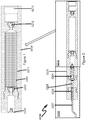
- a downhole wellbore time delay tool (0210) for use in a wellbore casing comprises a reservoir (0211) for containing a reactive fluid (0201), an actuating device (0202) such as a rupture disk, a mechanical restraining element (0203) such as a nut and mechanically connected to a wellbore device such as an energetic device (0220) with firing pin (0204), a percussion initiator (0205), a booster (0206) and a detonating cord (0207).
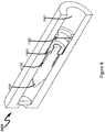
- a detailed view of the wellbore tool (0210) is illustrated in FIG. 1 .
- the entire tool (0200) may be piped into the casing string as an integral part of the string and positioned where functioning of the tool is desired or the tool may be deployed to the desired location with TCP, CT or a wire line.
- the wellbore may be cemented or not.
- the fluid in the reservoir (0211) is held at an initial position by the actuating device (0202), such as a rupture disk.
- the tool mandrel is machined to accept the actuating device (0202) (such as rupture discs) that ultimately controls the flow of reactive fluid (0201).
- the fluid reservoir (0211) may be further installed in within a fluid holding body (0208).
- the fluid holding body (0208) may be operatively connected to a body (0209) of the energetic device (0220).
- the rated pressure of the actuating device may range from 500 PSI to 15000 PSI.
- the reservoir (0211) may be in fluid communication with the mechanical restraining element via the actuation device (0202).
- the reactive fluid may be directly in fluid communication with the mechanical restraining element via the actuation device (0202) without a reservoir.
- the mechanical restraining element may not be in fluid communication initially with any fluid.
- wellbore fluids may enter and react with the mechanical restraining element.
- a pressure port (0213) may be attached to another end of the reservoir through another actuating device (0212).
- the reservoir (0211) may be a holding tank that may be positioned inside a fluid holding body (0208) of a well casing.
- the volume of the reservoir may range from 25 ml to 5 liters.
- the material of the reservoir may be chosen so that the reactive fluid inside the reservoir does not react with the material of the reservoir and therefore does not corrode or erode the reservoir (0211).
- the material of the reservoir may be selected from a group comprising: metal, ceramic, plastic, degradable, long term degradable, glass, composite or combinations thereof.
- the reservoir may also be pressurized so that there is sufficient flow of the reactive fluid towards the restraining element.
- the actuation device (0202) may be a reverse acting rupture disk that blocks fluids communication between the reactive fluid and the restraining element.
- the actuation device (0212) ruptures or actuates when a pressure in the wellbore through the pressure port (0213) exceeds a rated pressure of the actuating device (0212). After the actuating device (0212) rupture, the pressure acting through the pressure port (0213) may act on the fluid which further acts on the actuating device (0202).
- the actuating device is an electronic switch that is actuated by a signal from a device storing a stored energy.
- the pressure on the actuation device (0202) may be ramped up to the rated pressure with pressure from the reactive fluid.
- the reactive fluid (0201) is configured to react with the mechanical restraining element (0203) at a temperature expected to be encountered in the wellbore.
- a physical property change in the restraining element may occur at a pre-determined temperature expected to be encountered in the wellbore casing.
- the pre-determined temperature ranges from 25°C - 250°C.
- the mechanical restraining element (0203) may be a nut, a shear pin, or a holding device that degrades as the reaction takes place. Upon further degradation, the mechanical restraining element (0203) may release a restraint on the energetic device (0220) and enable the entire pressure or stored energy to act on an end of the energetic device (0220).
- the reactive fluid is selected from a group comprising: fresh water, salt water, KCL, NaCl, HCL, or hydrocarbons.
- the energetic device (0220) may be operatively connected to the mechanical restraining element via threads, seals or a connecting element.
- the tool mandrel may be machined to accept the wellbore reservoir, the actuating device and the wellbore device such as a firing pin assembly.
- the mechanical restraining element may be a nut that may be screwed or attached to a counterpart in the wellbore device.
- the restraining element may be a tensile member.
- the wellbore device may be an energetic device (0220) with a firing pin (0204) as illustrated in FIG. 2 (0200).
- the actuating device (0202) when a stored energy, such as a pressure from a fluid, is applied on the firing pin assembly, the actuating device (0202) is actuated and the reactive fluid (0201) from the reservoir (0211) comes into contact with the mechanical restraining element (0203) and enables a physical property change in the mechanical restraining element such that the stored energy applied on the wellbore device is delayed by a pre-determined time delay while the mechanical restraining element undergoes the physical property change.
- the physical property change may enable the restraining element to change shape for a pre-determined period of time.
- the physical property may be strength, ductility or elasticity.
- a known delay interval between pressuring the tubing to a second pre-determined level and the actual firing of the perforating gun may be achieved by the pre-determined time delay.
- a delay means, to move a firing pin holder out of locking engagement with a firing pin to release the firing pin may be achieved by the predetermined time interval. 5.
- the firing pin (0204) may contact a percussion detonator/initiator (0205) that connects to a bidirectional booster (0206).
- the bidirectional booster (0206) may accept a detonation input from the detonator.
- the detonating cord (0207) may be initiated in turn by the booster (0206).
- the firing pin When the firing pin is actuated after the mechanical restraint (0203) is released, the firing pin (0204) may contact a percussion detonator (0205) and in turn initiate a detonator through a booster (0206) and a detonating cord (0207).
- the stored energy is applied from a spring.
- the stored energy is applied from a pressure from a fluid and a seal.
- the stored energy is applied from a magnetic field.
- the stored energy is applied from a weight.
- the pre-determined time delay ranges from 1 hour to 48 hours. According to a more preferred exemplary embodiment, the pre-determined time delay ranges from 2 days to 14 days. According to a most preferred exemplary embodiment, the pre-determined time delay ranges from .01 seconds to 1 hour.
- the chemical reaction may be an exothermic reaction that gives off heat.
- the energy needed to initiate the chemical reaction may be less than the energy that is subsequently released by the chemical reaction.
- the chemical reaction may be an endothermic reaction that absorbs heat. The energy needed to initiate the chemical reaction may be greater than the energy that is subsequently released by the chemical reaction.
- the rate of the chemical reaction may be accelerated or retarded based on factors such as nature of the reactants, particle size of the reactants, concentration of the reactants, pressure of the reactants, temperature and catalysts.
- a catalyst may be added to alter the rate of the reaction.
- the material of the restraining element may be selected from a group comprising: mixture of aluminum, copper sulfate, potassium chlorate, and calcium sulfate, iron, magnesium, steel, plastic, degradable, magnesium-iron alloy, particulate oxide of an alkali or alkaline earth metal and a solid, particulate acid or strongly acid salt, or mixtures thereof.
- the catalyst may be selected from a group comprising salts.
- the material of the restraining element may be selected from a group comprising: metal, non-metal or alloy.
- the mechanical restraining element is a restrictive plug element.
- the restriction plug element may be a ball or a plug that is used to isolate pressure communication between zones or stages in a well casing.
- the pre-determined time delay is determined by concentration of the reactive fluids. According to another preferred exemplary embodiment the pre-determined time delay is determined by reaction rate of the reactive fluids with the mechanical restraining element. According to yet another preferred exemplary embodiment the pre-determined time delay is determined by reaction time of the reactive fluids with the mechanical restraining element. According to a further preferred exemplary embodiment the pre-determined time delay is determined by masking a contact area of the mechanical restraining element. According to a further preferred exemplary embodiment the pre-determined time delay is determined by masking a total area of the mechanical restraining element in contact with the mechanical restraining element.
- the shape of the mechanical restraining element is selected from a group comprising: square, circle, oval, and elongated.
- a sealed cap may seal the exposed end of the reservoir to physically protect the reservoir from undesired wellbore conditions.
- a multi stage restraining element comprising a blocking member and a restraining member may further increase a time delay.
- mechanical restraining element (0203) may be coupled with a blocking member that may have a different composition and reaction time with the fluid in the reservoir.
- the blocking member may react with the fluid for a period of time and may restrict fluid access to the mechanical restraining element for a pre-determined period of time.
- the multi stage restraining element may not limited to a blocking member and a restraining element. Any number of blocking members and restraining elements may be used in combination to achieve a desired time delay.
- the reaction times and therefore the time delays of each of the bonding members with the fluid may be characterized at various temperatures expected in the wellbore.
- the reservoir may be filled with wellbore fluids.
- the reservoir may be empty when deployed into the wellbore and later filled with wellbore fluids.
- a time vs temperature chart for the restraining element may be characterized with different compositions of wellbore fluids expected in the wellbore at temperatures expected in the wellbore casing.
- the fluid reservoir may be partially filled with the known fluid and wellbore fluids may fill the remaining portion of the reservoir.
- the reservoir may be filled with the known fluid, wellbore fluids or a combination thereof.
- the mechanical restraining element may comprise one or more material types that react and have different degradation rates in one or more fluid types. The desired time delay may be achieved with a combination of fluid types and restraining element material types.
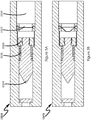
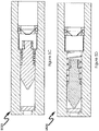
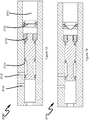
- FIG. 3A-3D generally illustrates different positions of a firing pin assembly (0304).
- the positions include an initial set up position (0300), an actuation position (0310), a degradation position (0320) and a triggering position (0330).
- the entire tool may be piped into the casing string as an integral part of the string and positioned where functioning of the tool is desired.
- the tool may be a firing pin assembly that is positioned where detonation, perforation of a formation and fluid injection into a formation is desired.
- the tool may be installed in either direction with no change in its function.
- a detailed view of the tool in the initial set up position is shown in FIG.3 (0300) where in the fluid in the reservoir is held by the actuating device (0302).
- the pressure is increased for example with TCP.
- the tool then moves to the actuation position (0310), when pressure acting on the actuating device (0302) exceeds its rated pressure, the actuation device ruptures and enables reactive fluid in the fluid reservoir (0301) to enter the adjacent chamber and contacts the restraining element. Subsequently, after elapse of a pre-determined time delay, the restraining element degrades or changes shape due to the chemical reaction as illustrated in the degradation position in FIG. 3C (0320).
- the firing pin (0304) in the energetic device is triggered as the restraining element (0303) no longer holds or restrains the firing pin (0304) due to change of shape or strength.
- the entire stored energy may be applied to move the firing pin and contact a bidirectional booster, after the pre-determined time delay in the degradation position.
- the stored energy may be applied by pressure and seal, magnetic field, a weight, a spring or combination thereof.
- FIG.4A (0400) generally illustrates a perspective view of the downhole delay tool with a firing pin as the wellbore device.
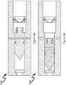
- FIGS. 3E-3H a downhole delay tool with a firing pin and a shear pin restraint is generally illustrated in FIGS. 3E-3H .
- FIG. 3E As generally illustrated in more detail in FIG. 3E (0350), FIG. 3F (0360), FIG. 3G (0370), FIG. 3H (0380), wherein the downhole wellbore delay tool is deployed inside a wellbore casing.
- FIG. 3E-3H generally illustrates different positions of a firing pin assembly (0324) restrained by a shear pin (0325) in addition to a mechanical restraining element (0323). The positions include an initial set up position (0350), an actuation position (0360), a degradation position (0370) and a triggering position (0380).
- FIG.3E A detailed view of the tool in the initial set up position is shown in FIG.3E (0350) wherein the fluid in the reservoir is held by the actuating device (0322).
- the pressure is increased for example with TCP.
- the tool then moves to the actuation position (0360), when pressure acting on the actuating device (0322) exceeds its rated pressure, the actuation device ruptures and enables reactive fluid in the fluid reservoir (0321) or well fluids from the wellbore casing to enter the adjacent chamber and contacts the restraining element.
- the restraining element degrades or changes shape due to the chemical reaction as illustrated in the degradation position in FIG. 3G (0370).
- FIG.4B generally illustrates a perspective view of the downhole delay tool with an energetic device and a firing pin and a shear pin restraint mechanism as the wellbore device.
- the mechanical restraining element (0323) could be degraded, releasing the shear pin (0325), and then the tool would have to be pumped to a pressure sufficient to shear the shear pins (0325), which would allow the firing pin (0324) to strike a percussion initiator (not shown).
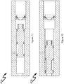
- FIGS. 5A-5D a downhole delay tool with a firing pin and a spring is generally illustrated in FIGS. 5A-5D .
- FIG. 5A-5D generally illustrates different positions of a firing pin assembly (0504) restrained by a spring (0505). The positions include an initial set up position (0500), an actuation position (0510), a degradation position (0520) and a triggering position (0530).
- FIG.5A A detailed view of the tool in the initial set up position is shown in FIG.5A (0500) wherein the fluid in the reservoir is held by the actuating device (0502).
- the pressure is increased for example with TCP.
- the tool then moves to the actuation position (0510), when pressure acting on the actuating device (0502) exceeds its rated pressure, the actuation device ruptures and enables reactive fluid in the fluid reservoir (0501) to enter the adjacent chamber and contacts the restraining element. Subsequently, after elapse of a pre-determined time delay, the restraining element degrades or changes shape due to the chemical reaction as illustrated in the degradation position in FIG. 5C (0520).
- FIG.6 (0600) generally illustrates a perspective view of the downhole delay tool with an energetic device and a firing pin and a spring loading mechanism as the wellbore device.
- FIGS. 7A-7D a downhole delay tool with a spool valve is generally illustrated in FIGS. 7A-7D .
- a detailed view of the tool in the initial set up position is shown in FIG.7A (0700) wherein the fluid in the reservoir is held by the actuating device (0702) and a sleeve (0704) may block ports (0705, 0706) and disable pressure or fluid communication to a hydrocarbon formation.
- the pressure is increased for example with TCP.
- the tool then moves to the actuation position (0710), when pressure acting on the actuating device (0702) exceeds its rated pressure, the actuation device ruptures and enables reactive fluid in the fluid reservoir (0701 to enter the adjacent chamber and contacts the restraining element (0703). Subsequently, after elapse of a pre-determined time delay, the restraining element degrades or changes shape due to the chemical reaction as illustrated in the degradation position in FIG. 7C (0720). In the triggering position (0730), a movement in a sleeve (0704) in the spool valve is triggered as the restraining element (0703) no longer holds or restrains the sleeve (0704) due to change of shape.
- the sleeve (0704) may slide and unblock one or more ports (0705, 0706) and enable pressure or fluid communication to a hydrocarbon formation. Similar to the mechanical restraining element (0703) in FIG 7A (0700), a tensile member (0713) is generally illustrated in FIG. 7E (0740). The tensile member (0713) may react with a reactive fluid from a reservoir (0711) and provide a time delay for the tensile member (0713) to break and enable a sleeve in the spool valve to slide and open ports (0714, 0715). FIG.
- FIG. 7F generally illustrates a sleeve position after the ports (0714, 0715) are opened to the hydrocarbon formation.
- FIG.8 (0800) generally illustrates a perspective view of the downhole delay tool with a spool valve and a sliding sleeve as a wellbore device.
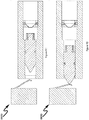
- FIGS. 9A-9D a downhole delay tool with a pin and a switch is generally illustrated in FIGS. 9A-9D .
- FIG. 9A-9D generally illustrate different positions of a firing pin assembly (0904) and a switch (0906) with a contact (0905). The positions include an initial set up position (0900), an actuation position (0910), a degradation position (0920) and a triggering position (0930).
- FIG.9A A detailed view of the tool in the initial set up position is shown in FIG.9A (0900) where in the fluid in the reservoir is held by the actuating device (0902).
- the electrical contact may not be connected to the pin (0904).
- the pressure is increased for example with TCP.
- the tool then moves to the actuation position (0910), when pressure acting on the actuating device (0902) exceeds its rated pressure, the actuation device ruptures and enables reactive fluid in the fluid reservoir (0901) to enter the adjacent chamber and contacts the restraining element (0903). Subsequently, after elapse of a pre-determined time delay, the restraining element degrades or changes shape due to the chemical reaction as illustrated in the degradation position in FIG.
- FIG.10 generally illustrates a perspective view of the downhole delay tool with a pin and a switch as the wellbore device.
- Figure 11 (1100) generally illustrates a degradable restriction element (1103) blocking a flow channel (1104) in a wellbore casing.
- a known reactive fluid may be provided to react with the degradable restriction element (1103). After an elapse of a predictable time period, the degradable restriction element (1103) may degrade or change physical shape to enable fluid communication through the channel (1104).
- a preferred exemplary flowchart embodiment of a time delay method may be generally described in terms of the following steps:
- a preferred exemplary flowchart embodiment of a time delay firing method in conjunction with a downhole wellbore time delay tool may be generally described in terms of the following steps:
- a time (1401) vs temperature (1402) reaction curve is generally illustrated in FIG. 14 (1400).
- the nature of the curve depends on the known fluid type reacting with a material of a mechanical restraining element.
- curve (1410) may represent a fluid type "A” reacting with a material "A” of a mechanical restraining element
- curve (1420) may represent a fluid type B reacting with a material "B”
- curve (1430) may represent a fluid type "C” reacting with a material "C”.
- the reactive fluid may be a known fluid such as fresh water, salt water, KCL, NaCl, HCL, oil, hydrocarbon or combination thereof.
- the fluid may be contained in a reservoir (0211) as illustrated in FIG. 2 .
- the mechanical restraining element may be a nut (0203) as illustrated in FIG. 2 .
- the material of the mechanical restraining element may be a metal, a non-metal or an alloy.
- the material of the mechanical restraining element may be Aluminum, Magnesium or an aluminum-Magnesium alloy.
- a curve may be drawn for each combination of a known fluid and a known material.
- a model may be developed from the curve in order to calculate a time delay when a temperature is determined in a wellbore. For example, at a temperature of 180°F the time delay for curve (1410) may be 4 minutes (1411). Similarly, the time delay for curve (1420) may be 20 minutes (1412) and time delay for curve (1430) may be 74 minutes (1413).
- a model may be developed for each combination of a known fluid and material.
- the model may be stored and used to determine a time delay when a temperature is determined in a wellbore casing.
- the predictability of time delay based on a measured temperature enables a triggering event to be delayed reliably with a greater accuracy.
- Any time delay may be achieved by changing the combination of the reactive fluid and material of the restraining element.
- the reservoir may be filled with the known fluid, wellbore fluids or a combination thereof.
- the mechanical restraining element may comprise one or more material types that react and have different degradation rates in one or more fluid types.
- the desired time delay may be achieved with a combination of fluid types and restraining element material types.
- a predictable downhole time delay tool for determining time delay may comprise a known fluid and a known mechanical restraining element wherein the known fluid is configured to react with the mechanical restraining element; and the time delay is determined based upon a condition encountered in the wellbore when the known fluid reacts with the mechanical restraining element.
- the time delay is further based on a pre-determined reaction curve between the known fluid and said the mechanical restraining element.
- the wellbore condition is wellbore temperature.
- the wellbore temperature is determined by distributed temperature sensing.
- the known fluid may be wellbore fluids that are sampled and characterized for time delay and temperature.
- the known fluid may be contained in a reservoir or an open chamber configured to permit fluid to interact with a restraining element.
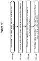
- a preferred exemplary flowchart embodiment of a predictable time delay method the method operating in conjunction with a predictable downhole time delay tool comprising a known fluid and a known mechanical restraining element may be generally described in terms of the following steps:
- the present invention system anticipates a wide variety of variations in the basic theme of time delay, but can be generalized as a downhole wellbore time delay tool for use with a wellbore device in a wellbore casing, comprising:
- the present invention method anticipates a wide variety of variations in the basic theme of implementation, but can be generalized as a downhole wellbore time delay tool for use with a wellbore device in a wellbore casing, comprising:
- the present invention anticipates a wide variety of variations in the basic theme of oil and gas extraction.
- the examples presented previously do not represent the entire scope of possible usages. They are meant to cite a few of the almost limitless possibilities.
- This basic system and method may be augmented with a variety of ancillary embodiments, including but not limited to:
Landscapes
- Geology (AREA)
- Life Sciences & Earth Sciences (AREA)
- Engineering & Computer Science (AREA)
- Mining & Mineral Resources (AREA)
- Environmental & Geological Engineering (AREA)
- Fluid Mechanics (AREA)
- Physics & Mathematics (AREA)
- General Life Sciences & Earth Sciences (AREA)
- Geochemistry & Mineralogy (AREA)
- Fluid-Pressure Circuits (AREA)
- Micromachines (AREA)
- Geophysics And Detection Of Objects (AREA)
- Feeding, Discharge, Calcimining, Fusing, And Gas-Generation Devices (AREA)
Claims (16)
- Outil à action retardée pour puits de forage (0210) destiné à être utilisé dans un cuvelage de puits de forage, ledit outil à action retardée pour puits de forage comprenant :un corps (0208) qui définit un volume interne (0211), le volume interne (0211) étant fermé à une première extrémité par un premier dispositif d'actionnement (0202) et à une deuxième extrémité par un deuxième dispositif d'actionnement (0212) ;un élément de retenue mécanique (0203) configuré pour réagir avec un liquide réactif (0201), l'élément de retenue mécanique (0203) étant relié mécaniquement à un dispositif de puits de forage (0220) ;le volume interne (0211) à l'intérieur du corps (0208) de l'outil à action retardée pour puits de forage (210) étant configuré pour contenir le fluide réactif (0201), le fluide réactif provoquant un changement physique dans l'élément de retenue mécanique (0203) lorsqu'il est en contact avec celui-ci ; etle premier dispositif d'actionnement (0202) se trouvant dans l'outil à action retardée pour puits de forage (0210) entre le volume interne (0211) et l'élément de retenue mécanique (0203), et bloquant la communication fluidique entre le volume interne (0211) et l'élément de retenue mécanique (0203), et permettant la communication fluidique lorsque le premier dispositif d'actionnement (0202) est ouvert pour l'écoulement du fluide, et le deuxième dispositif d'actionnement (0212) se trouvant dans l'outil à action retardée pour puits de forage (0210) et étant actionné lorsqu'une pression dans le cuvelage de puits de forage dépasse une pression assignée ;moyennant quoi, l'élément de retenue mécanique (0203) retient le dispositif de puits de forage (0220) et est configuré pour libérer le dispositif de puits de forage (0220) de la retenue après un retard, le retard étant basé sur un temps de réaction pour le changement de propriété physique de l'élément de retenue mécanique (0203) .
- Outil à action retardée pour puits de forage (0210) selon la revendication 1, le liquide réactif (0201) étant un produit chimique qui réagit avec l'élément de retenue mécanique (0203) à une température prévue d'être rencontrée dans le cuvelage de puits de forage.
- Outil à action retardée pour puits de forage (0210) selon la revendication 2, le liquide réactif (0201) réagissant avec l'élément de retenue mécanique (0203) à une température dans la plage de 25 °C à 250 °C.
- Outil à action retardée pour puits de forage (0210) selon la revendication 1, le premier dispositif d'actionnement (0202) étant configuré pour être activé par l'énergie appliquée à un ensemble percuteur (0304).
- Outil à action retardée pour puits de forage (0210) selon la revendication 1, l'outil à action retardée pour puits de forage (0210) étant configuré pour être déployé avec un outil de câble de forage ou avec la perforation transportée par colonne de production.
- Outil à action retardée pour puits de forage (0210) selon la revendication 1, l'outil à action retardée pour puits de forage (0210) étant configuré pour être pompé vers le bas sous la forme d'un outil de pompage vers le bas.
- Outil à action retardée pour puits de forage (0210) selon la revendication 1, le liquide réactif (0201) comprenant : de l'eau, de l'eau salée, du KCl, du NaCl, du HCl, de l'huile ou un hydrocarbure.
- Outil à action retardée pour puits de forage (0210) selon la revendication 1, l'action retardée s'étendant de 1 heure à 48 heures, ou
outil à action retardée pour puits de forage (0210) selon la revendication 1, l'action retardée s'étendant de 0,01 seconde à 1 heure. - Outil à action retardée pour puits de forage (0210) selon la revendication 1, le premier dispositif d'actionnement (0202) étant un disque de rupture ; le disque de rupture étant activé par la pression dans le cuvelage de puits de forage.
- Outil à action retardée pour puits de forage (0210) selon la revendication 1, le dispositif de puits de forage (0220) étant un percuteur (0204) pour un dispositif énergétique ; le percuteur (0204) étant configuré pour être libéré lorsque l'élément de retenue mécanique (0203) subit un changement de propriété physique.
- Outil à action retardée pour puits de forage (0210) selon la revendication 1, l'élément de retenue mécanique (0203) comprenant un écrou.
- Outil à action retardée pour puits de forage (0210) selon la revendication 1, le retard étant déterminé par une composition du liquide réactif (0201).
- Outil à action retardée pour puits de forage (0210) selon la revendication 1, le retard étant déterminé par masquage d'une zone de contact potentiel entre l'élément de retenue mécanique (0203) et le fluide réactif (0201).
- Outil à action retardée pour puits de forage (0210) selon la revendication 1, un matériau dudit élément de retenue mécanique (0203) comprenant : du magnésium, de l'aluminium, ou un alliage d'aluminium-magnésium.
- Outil à action retardée pour puits de forage (0210) selon la revendication 1, l'outil (0210) étant configuré pour permettre à tout fluide de puits de forage dans le cuvelage de puits de forage de réagir en outre avec ledit élément de retenue mécanique (0203).
- Outil à action retardée pour puits de forage (0210) selon la revendication 1, le premier dispositif d'actionnement (0202) étant configuré pour être ouvert par l'application d'une pression depuis un cuvelage de puits de forage.
Applications Claiming Priority (3)
| Application Number | Priority Date | Filing Date | Title |
|---|---|---|---|
| US15/053,534 US10253597B2 (en) | 2016-02-25 | 2016-02-25 | Degradable material time delay system and method |
| US15/053,417 US10156126B2 (en) | 2016-02-25 | 2016-02-25 | Degradable material time delay system and method |
| PCT/US2017/014613 WO2017146849A1 (fr) | 2016-02-25 | 2017-01-23 | Système et procédé de temporisation par matériau dégradable |
Publications (3)
| Publication Number | Publication Date |
|---|---|
| EP3420181A1 EP3420181A1 (fr) | 2019-01-02 |
| EP3420181A4 EP3420181A4 (fr) | 2019-10-09 |
| EP3420181B1 true EP3420181B1 (fr) | 2020-10-28 |
Family
ID=59679433
Family Applications (1)
| Application Number | Title | Priority Date | Filing Date |
|---|---|---|---|
| EP17756953.0A Active EP3420181B1 (fr) | 2016-02-25 | 2017-01-23 | Système et procédé de temporisation par matériau dégradable |
Country Status (6)
| Country | Link |
|---|---|
| US (3) | US10253597B2 (fr) |
| EP (1) | EP3420181B1 (fr) |
| CN (1) | CN109072684B (fr) |
| CA (1) | CA3015333C (fr) |
| MX (1) | MX2018010232A (fr) |
| WO (1) | WO2017146849A1 (fr) |
Families Citing this family (12)
| Publication number | Priority date | Publication date | Assignee | Title |
|---|---|---|---|---|
| US10961827B2 (en) * | 2017-08-02 | 2021-03-30 | Expro Americas, Llc | Tubing conveyed perforating system with safety feature |
| CN109083625B (zh) * | 2018-08-09 | 2021-08-06 | 营口市双龙射孔器材有限公司 | 一种全通径跨隔射孔-测试联作管柱的操作方法 |
| US11454087B2 (en) | 2018-09-25 | 2022-09-27 | Advanced Upstream Ltd. | Delayed opening port assembly |
| CN110374568B (zh) * | 2019-07-18 | 2021-06-08 | 中国石油集团渤海钻探工程有限公司 | 一种智能底段压裂滑套 |
| US11834936B2 (en) * | 2020-06-15 | 2023-12-05 | Geodynamics, Inc. | Dissolvable time delay firing head and method |
| CA3113269A1 (fr) | 2020-08-31 | 2022-02-28 | Advanced Upstream Ltd. | Reduction d'orifice avec sequence d'ouverture retardee |
| US12110756B2 (en) * | 2021-12-06 | 2024-10-08 | Canadian Casing Accessories Inc. | Modified cement plug and methods of use |
| US20230258055A1 (en) * | 2022-02-11 | 2023-08-17 | Baker Hughes Oilfield Operations Llc | Trigger for downhole tool, method and system |
| US12305472B2 (en) * | 2023-10-25 | 2025-05-20 | Tco As | Tensile release mechanism |
| US12241346B1 (en) * | 2023-11-01 | 2025-03-04 | Halliburton Energy Services, Inc. | Remotely operated three position spool valve |
| US12378862B1 (en) * | 2024-06-13 | 2025-08-05 | Saudi Arabian Oil Company | Particulate buffer for attenuating corrosion of dissolvable frac plug |
| CN118919002B (zh) * | 2024-10-09 | 2024-12-27 | 江苏通上新材料科技有限公司 | 一种电缆材料的绿色生产方法及系统 |
Family Cites Families (24)
| Publication number | Priority date | Publication date | Assignee | Title |
|---|---|---|---|---|
| US3010515A (en) * | 1958-03-31 | 1961-11-28 | John C Kinley | Time trip device |
| US3022822A (en) | 1960-04-11 | 1962-02-27 | Jersey Prod Res Co | Method of manipulating well tools |
| US4474242A (en) * | 1981-06-29 | 1984-10-02 | Schlumberger Technology Corporation | Annulus pressure controlled reversing valve |
| US4429741A (en) | 1981-10-13 | 1984-02-07 | Christensen, Inc. | Self powered downhole tool anchor |
| US4614156A (en) * | 1984-03-08 | 1986-09-30 | Halliburton Company | Pressure responsive explosion initiator with time delay and method of use |
| US5115865A (en) * | 1990-06-15 | 1992-05-26 | James V. Carisella | Method and apparatus for selectively actuating wellbore perforating tools |
| US5301755A (en) | 1993-03-11 | 1994-04-12 | Halliburton Company | Air chamber actuator for a perforating gun |
| US6230822B1 (en) | 1995-02-16 | 2001-05-15 | Baker Hughes Incorporated | Method and apparatus for monitoring and recording of the operating condition of a downhole drill bit during drilling operations |
| AU8164898A (en) | 1997-06-27 | 1999-01-19 | Baker Hughes Incorporated | Drilling system with sensors for determining properties of drilling fluid downhole |
| US8211247B2 (en) * | 2006-02-09 | 2012-07-03 | Schlumberger Technology Corporation | Degradable compositions, apparatus comprising same, and method of use |
| US7726406B2 (en) | 2006-09-18 | 2010-06-01 | Yang Xu | Dissolvable downhole trigger device |
| US8485265B2 (en) | 2006-12-20 | 2013-07-16 | Schlumberger Technology Corporation | Smart actuation materials triggered by degradation in oilfield environments and methods of use |
| US7896072B2 (en) | 2008-11-05 | 2011-03-01 | Halliburton Energy Services, Inc. | Calorimetric distributed temperature system and methods |
| US8672031B2 (en) | 2009-03-13 | 2014-03-18 | Schlumberger Technology Corporation | Perforating with wired drill pipe |
| US8276670B2 (en) * | 2009-04-27 | 2012-10-02 | Schlumberger Technology Corporation | Downhole dissolvable plug |
| US8726996B2 (en) | 2009-06-02 | 2014-05-20 | Schlumberger Technology Corporation | Device for the focus and control of dynamic underbalance or dynamic overbalance in a wellbore |
| US8579036B2 (en) * | 2011-03-14 | 2013-11-12 | Baker Hughes Incorporated | Valving system, method of adjusting a valve and method of fracing a wellbore |
| US9033046B2 (en) | 2012-10-10 | 2015-05-19 | Baker Hughes Incorporated | Multi-zone fracturing and sand control completion system and method thereof |
| CN104838081B (zh) * | 2013-02-26 | 2017-04-19 | 哈利伯顿能源服务公司 | 井下工具的远程液压控制 |
| US9441437B2 (en) * | 2013-05-16 | 2016-09-13 | Halliburton Energy Services, Inc. | Electronic rupture discs for interventionless barrier plug |
| US9708884B2 (en) | 2013-10-31 | 2017-07-18 | Jeffrey Stephen Epstein | Sacrificial isolation member for fracturing subsurface geologic formations |
| US20150247084A1 (en) | 2014-03-03 | 2015-09-03 | Jeffrey Stephen Epstein | Ceramic isolation ball for fracturing subsurface geologic formations |
| US9062543B1 (en) | 2014-08-13 | 2015-06-23 | Geodyanmics, Inc. | Wellbore plug isolation system and method |
| US10526868B2 (en) * | 2014-08-14 | 2020-01-07 | Halliburton Energy Services, Inc. | Degradable wellbore isolation devices with varying fabrication methods |
-
2016
- 2016-02-25 US US15/053,534 patent/US10253597B2/en active Active
- 2016-02-25 US US15/053,417 patent/US10156126B2/en active Active
- 2016-07-26 US US15/220,042 patent/US10208570B2/en active Active
-
2017
- 2017-01-23 WO PCT/US2017/014613 patent/WO2017146849A1/fr not_active Ceased
- 2017-01-23 MX MX2018010232A patent/MX2018010232A/es unknown
- 2017-01-23 CA CA3015333A patent/CA3015333C/fr active Active
- 2017-01-23 CN CN201780024636.1A patent/CN109072684B/zh active Active
- 2017-01-23 EP EP17756953.0A patent/EP3420181B1/fr active Active
Non-Patent Citations (1)
| Title |
|---|
| None * |
Also Published As
| Publication number | Publication date |
|---|---|
| CN109072684A (zh) | 2018-12-21 |
| US20170247977A1 (en) | 2017-08-31 |
| WO2017146849A1 (fr) | 2017-08-31 |
| CA3015333A1 (fr) | 2017-08-31 |
| CN109072684B (zh) | 2020-07-07 |
| US10208570B2 (en) | 2019-02-19 |
| CA3015333C (fr) | 2020-01-07 |
| US20170247982A1 (en) | 2017-08-31 |
| US10253597B2 (en) | 2019-04-09 |
| EP3420181A4 (fr) | 2019-10-09 |
| MX2018010232A (es) | 2019-05-02 |
| US10156126B2 (en) | 2018-12-18 |
| EP3420181A1 (fr) | 2019-01-02 |
| US20170247988A1 (en) | 2017-08-31 |
Similar Documents
| Publication | Publication Date | Title |
|---|---|---|
| CA3015333C (fr) | Systeme de temporisation par materiau degradable | |
| US9759039B1 (en) | Degradable material time delay system and method | |
| US10787884B2 (en) | Downhole tool having a dissolvable plug | |
| US9157718B2 (en) | Interruptor sub, perforating gun having the same, and method of blocking ballistic transfer | |
| AU2010341610B2 (en) | Well tools operable via thermal expansion resulting from reactive materials | |
| US20080149345A1 (en) | Smart actuation materials triggered by degradation in oilfield environments and methods of use | |
| CA3058349C (fr) | Outils de fond de trou a degradation commandee et procede | |
| US10689948B2 (en) | Electronic time delay apparatus and method | |
| US20140338923A1 (en) | Electronic rupture discs for interventionless barrier plug | |
| US9273535B1 (en) | Hydraulic flow restriction tube time delay system and method | |
| US11608712B2 (en) | Actuator apparatus using a pin-puller | |
| GB2612622A (en) | A chemical reaction heat source composition for use in downhole operations and associated apparatus and methods | |
| US10036230B2 (en) | Hydraulic flow restriction tube time delay system and method | |
| CA3064476C (fr) | Appareil et procede de retard de temps electronique | |
| EP3081739A2 (fr) | Système et procédé de retard de durée de tube de restriction d'écoulement hydraulique |
Legal Events
| Date | Code | Title | Description |
|---|---|---|---|
| STAA | Information on the status of an ep patent application or granted ep patent |
Free format text: STATUS: THE INTERNATIONAL PUBLICATION HAS BEEN MADE |
|
| PUAI | Public reference made under article 153(3) epc to a published international application that has entered the european phase |
Free format text: ORIGINAL CODE: 0009012 |
|
| STAA | Information on the status of an ep patent application or granted ep patent |
Free format text: STATUS: REQUEST FOR EXAMINATION WAS MADE |
|
| 17P | Request for examination filed |
Effective date: 20180917 |
|
| AK | Designated contracting states |
Kind code of ref document: A1 Designated state(s): AL AT BE BG CH CY CZ DE DK EE ES FI FR GB GR HR HU IE IS IT LI LT LU LV MC MK MT NL NO PL PT RO RS SE SI SK SM TR |
|
| AX | Request for extension of the european patent |
Extension state: BA ME |
|
| DAV | Request for validation of the european patent (deleted) | ||
| DAX | Request for extension of the european patent (deleted) | ||
| A4 | Supplementary search report drawn up and despatched |
Effective date: 20190906 |
|
| RIC1 | Information provided on ipc code assigned before grant |
Ipc: E21B 34/06 20060101AFI20190902BHEP Ipc: E21B 43/12 20060101ALI20190902BHEP Ipc: E21B 34/08 20060101ALI20190902BHEP Ipc: E21B 34/00 20060101ALI20190902BHEP Ipc: E21B 43/26 20060101ALI20190902BHEP Ipc: E21B 43/11 20060101ALI20190902BHEP |
|
| GRAP | Despatch of communication of intention to grant a patent |
Free format text: ORIGINAL CODE: EPIDOSNIGR1 |
|
| STAA | Information on the status of an ep patent application or granted ep patent |
Free format text: STATUS: GRANT OF PATENT IS INTENDED |
|
| INTG | Intention to grant announced |
Effective date: 20200526 |
|
| GRAS | Grant fee paid |
Free format text: ORIGINAL CODE: EPIDOSNIGR3 |
|
| GRAA | (expected) grant |
Free format text: ORIGINAL CODE: 0009210 |
|
| STAA | Information on the status of an ep patent application or granted ep patent |
Free format text: STATUS: THE PATENT HAS BEEN GRANTED |
|
| AK | Designated contracting states |
Kind code of ref document: B1 Designated state(s): AL AT BE BG CH CY CZ DE DK EE ES FI FR GB GR HR HU IE IS IT LI LT LU LV MC MK MT NL NO PL PT RO RS SE SI SK SM TR |
|
| REG | Reference to a national code |
Ref country code: GB Ref legal event code: FG4D |
|
| REG | Reference to a national code |
Ref country code: CH Ref legal event code: EP |
|
| REG | Reference to a national code |
Ref country code: DE Ref legal event code: R096 Ref document number: 602017026405 Country of ref document: DE |
|
| REG | Reference to a national code |
Ref country code: AT Ref legal event code: REF Ref document number: 1328418 Country of ref document: AT Kind code of ref document: T Effective date: 20201115 |
|
| REG | Reference to a national code |
Ref country code: IE Ref legal event code: FG4D |
|
| REG | Reference to a national code |
Ref country code: AT Ref legal event code: MK05 Ref document number: 1328418 Country of ref document: AT Kind code of ref document: T Effective date: 20201028 |
|
| REG | Reference to a national code |
Ref country code: NL Ref legal event code: MP Effective date: 20201028 |
|
| PG25 | Lapsed in a contracting state [announced via postgrant information from national office to epo] |
Ref country code: NO Free format text: LAPSE BECAUSE OF FAILURE TO SUBMIT A TRANSLATION OF THE DESCRIPTION OR TO PAY THE FEE WITHIN THE PRESCRIBED TIME-LIMIT Effective date: 20210128 Ref country code: RS Free format text: LAPSE BECAUSE OF FAILURE TO SUBMIT A TRANSLATION OF THE DESCRIPTION OR TO PAY THE FEE WITHIN THE PRESCRIBED TIME-LIMIT Effective date: 20201028 Ref country code: PT Free format text: LAPSE BECAUSE OF FAILURE TO SUBMIT A TRANSLATION OF THE DESCRIPTION OR TO PAY THE FEE WITHIN THE PRESCRIBED TIME-LIMIT Effective date: 20210301 Ref country code: GR Free format text: LAPSE BECAUSE OF FAILURE TO SUBMIT A TRANSLATION OF THE DESCRIPTION OR TO PAY THE FEE WITHIN THE PRESCRIBED TIME-LIMIT Effective date: 20210129 Ref country code: FI Free format text: LAPSE BECAUSE OF FAILURE TO SUBMIT A TRANSLATION OF THE DESCRIPTION OR TO PAY THE FEE WITHIN THE PRESCRIBED TIME-LIMIT Effective date: 20201028 |
|
| REG | Reference to a national code |
Ref country code: LT Ref legal event code: MG4D |
|
| PG25 | Lapsed in a contracting state [announced via postgrant information from national office to epo] |
Ref country code: BG Free format text: LAPSE BECAUSE OF FAILURE TO SUBMIT A TRANSLATION OF THE DESCRIPTION OR TO PAY THE FEE WITHIN THE PRESCRIBED TIME-LIMIT Effective date: 20210128 Ref country code: SE Free format text: LAPSE BECAUSE OF FAILURE TO SUBMIT A TRANSLATION OF THE DESCRIPTION OR TO PAY THE FEE WITHIN THE PRESCRIBED TIME-LIMIT Effective date: 20201028 Ref country code: IS Free format text: LAPSE BECAUSE OF FAILURE TO SUBMIT A TRANSLATION OF THE DESCRIPTION OR TO PAY THE FEE WITHIN THE PRESCRIBED TIME-LIMIT Effective date: 20210228 Ref country code: LV Free format text: LAPSE BECAUSE OF FAILURE TO SUBMIT A TRANSLATION OF THE DESCRIPTION OR TO PAY THE FEE WITHIN THE PRESCRIBED TIME-LIMIT Effective date: 20201028 Ref country code: PL Free format text: LAPSE BECAUSE OF FAILURE TO SUBMIT A TRANSLATION OF THE DESCRIPTION OR TO PAY THE FEE WITHIN THE PRESCRIBED TIME-LIMIT Effective date: 20201028 Ref country code: AT Free format text: LAPSE BECAUSE OF FAILURE TO SUBMIT A TRANSLATION OF THE DESCRIPTION OR TO PAY THE FEE WITHIN THE PRESCRIBED TIME-LIMIT Effective date: 20201028 Ref country code: ES Free format text: LAPSE BECAUSE OF FAILURE TO SUBMIT A TRANSLATION OF THE DESCRIPTION OR TO PAY THE FEE WITHIN THE PRESCRIBED TIME-LIMIT Effective date: 20201028 |
|
| PG25 | Lapsed in a contracting state [announced via postgrant information from national office to epo] |
Ref country code: NL Free format text: LAPSE BECAUSE OF FAILURE TO SUBMIT A TRANSLATION OF THE DESCRIPTION OR TO PAY THE FEE WITHIN THE PRESCRIBED TIME-LIMIT Effective date: 20201028 Ref country code: HR Free format text: LAPSE BECAUSE OF FAILURE TO SUBMIT A TRANSLATION OF THE DESCRIPTION OR TO PAY THE FEE WITHIN THE PRESCRIBED TIME-LIMIT Effective date: 20201028 |
|
| REG | Reference to a national code |
Ref country code: DE Ref legal event code: R097 Ref document number: 602017026405 Country of ref document: DE |
|
| PG25 | Lapsed in a contracting state [announced via postgrant information from national office to epo] |
Ref country code: RO Free format text: LAPSE BECAUSE OF FAILURE TO SUBMIT A TRANSLATION OF THE DESCRIPTION OR TO PAY THE FEE WITHIN THE PRESCRIBED TIME-LIMIT Effective date: 20201028 Ref country code: SK Free format text: LAPSE BECAUSE OF FAILURE TO SUBMIT A TRANSLATION OF THE DESCRIPTION OR TO PAY THE FEE WITHIN THE PRESCRIBED TIME-LIMIT Effective date: 20201028 Ref country code: SM Free format text: LAPSE BECAUSE OF FAILURE TO SUBMIT A TRANSLATION OF THE DESCRIPTION OR TO PAY THE FEE WITHIN THE PRESCRIBED TIME-LIMIT Effective date: 20201028 Ref country code: LT Free format text: LAPSE BECAUSE OF FAILURE TO SUBMIT A TRANSLATION OF THE DESCRIPTION OR TO PAY THE FEE WITHIN THE PRESCRIBED TIME-LIMIT Effective date: 20201028 Ref country code: EE Free format text: LAPSE BECAUSE OF FAILURE TO SUBMIT A TRANSLATION OF THE DESCRIPTION OR TO PAY THE FEE WITHIN THE PRESCRIBED TIME-LIMIT Effective date: 20201028 Ref country code: CZ Free format text: LAPSE BECAUSE OF FAILURE TO SUBMIT A TRANSLATION OF THE DESCRIPTION OR TO PAY THE FEE WITHIN THE PRESCRIBED TIME-LIMIT Effective date: 20201028 |
|
| PG25 | Lapsed in a contracting state [announced via postgrant information from national office to epo] |
Ref country code: MC Free format text: LAPSE BECAUSE OF FAILURE TO SUBMIT A TRANSLATION OF THE DESCRIPTION OR TO PAY THE FEE WITHIN THE PRESCRIBED TIME-LIMIT Effective date: 20201028 Ref country code: DK Free format text: LAPSE BECAUSE OF FAILURE TO SUBMIT A TRANSLATION OF THE DESCRIPTION OR TO PAY THE FEE WITHIN THE PRESCRIBED TIME-LIMIT Effective date: 20201028 |
|
| REG | Reference to a national code |
Ref country code: CH Ref legal event code: PL |
|
| PLBE | No opposition filed within time limit |
Free format text: ORIGINAL CODE: 0009261 |
|
| STAA | Information on the status of an ep patent application or granted ep patent |
Free format text: STATUS: NO OPPOSITION FILED WITHIN TIME LIMIT |
|
| PG25 | Lapsed in a contracting state [announced via postgrant information from national office to epo] |
Ref country code: LU Free format text: LAPSE BECAUSE OF NON-PAYMENT OF DUE FEES Effective date: 20210123 |
|
| 26N | No opposition filed |
Effective date: 20210729 |
|
| REG | Reference to a national code |
Ref country code: BE Ref legal event code: MM Effective date: 20210131 |
|
| PG25 | Lapsed in a contracting state [announced via postgrant information from national office to epo] |
Ref country code: AL Free format text: LAPSE BECAUSE OF FAILURE TO SUBMIT A TRANSLATION OF THE DESCRIPTION OR TO PAY THE FEE WITHIN THE PRESCRIBED TIME-LIMIT Effective date: 20201028 Ref country code: FR Free format text: LAPSE BECAUSE OF NON-PAYMENT OF DUE FEES Effective date: 20210131 Ref country code: IT Free format text: LAPSE BECAUSE OF FAILURE TO SUBMIT A TRANSLATION OF THE DESCRIPTION OR TO PAY THE FEE WITHIN THE PRESCRIBED TIME-LIMIT Effective date: 20201028 |
|
| PG25 | Lapsed in a contracting state [announced via postgrant information from national office to epo] |
Ref country code: SI Free format text: LAPSE BECAUSE OF FAILURE TO SUBMIT A TRANSLATION OF THE DESCRIPTION OR TO PAY THE FEE WITHIN THE PRESCRIBED TIME-LIMIT Effective date: 20201028 Ref country code: CH Free format text: LAPSE BECAUSE OF NON-PAYMENT OF DUE FEES Effective date: 20210131 Ref country code: LI Free format text: LAPSE BECAUSE OF NON-PAYMENT OF DUE FEES Effective date: 20210131 |
|
| PG25 | Lapsed in a contracting state [announced via postgrant information from national office to epo] |
Ref country code: IE Free format text: LAPSE BECAUSE OF NON-PAYMENT OF DUE FEES Effective date: 20210123 |
|
| PG25 | Lapsed in a contracting state [announced via postgrant information from national office to epo] |
Ref country code: IS Free format text: LAPSE BECAUSE OF FAILURE TO SUBMIT A TRANSLATION OF THE DESCRIPTION OR TO PAY THE FEE WITHIN THE PRESCRIBED TIME-LIMIT Effective date: 20210228 |
|
| PG25 | Lapsed in a contracting state [announced via postgrant information from national office to epo] |
Ref country code: BE Free format text: LAPSE BECAUSE OF NON-PAYMENT OF DUE FEES Effective date: 20210131 |
|
| P01 | Opt-out of the competence of the unified patent court (upc) registered |
Effective date: 20230524 |
|
| PG25 | Lapsed in a contracting state [announced via postgrant information from national office to epo] |
Ref country code: CY Free format text: LAPSE BECAUSE OF FAILURE TO SUBMIT A TRANSLATION OF THE DESCRIPTION OR TO PAY THE FEE WITHIN THE PRESCRIBED TIME-LIMIT Effective date: 20201028 |
|
| PG25 | Lapsed in a contracting state [announced via postgrant information from national office to epo] |
Ref country code: HU Free format text: LAPSE BECAUSE OF FAILURE TO SUBMIT A TRANSLATION OF THE DESCRIPTION OR TO PAY THE FEE WITHIN THE PRESCRIBED TIME-LIMIT; INVALID AB INITIO Effective date: 20170123 |
|
| PG25 | Lapsed in a contracting state [announced via postgrant information from national office to epo] |
Ref country code: MK Free format text: LAPSE BECAUSE OF FAILURE TO SUBMIT A TRANSLATION OF THE DESCRIPTION OR TO PAY THE FEE WITHIN THE PRESCRIBED TIME-LIMIT Effective date: 20201028 |
|
| PG25 | Lapsed in a contracting state [announced via postgrant information from national office to epo] |
Ref country code: MT Free format text: LAPSE BECAUSE OF FAILURE TO SUBMIT A TRANSLATION OF THE DESCRIPTION OR TO PAY THE FEE WITHIN THE PRESCRIBED TIME-LIMIT Effective date: 20201028 |
|
| PG25 | Lapsed in a contracting state [announced via postgrant information from national office to epo] |
Ref country code: TR Free format text: LAPSE BECAUSE OF FAILURE TO SUBMIT A TRANSLATION OF THE DESCRIPTION OR TO PAY THE FEE WITHIN THE PRESCRIBED TIME-LIMIT Effective date: 20201028 |
|
| PGFP | Annual fee paid to national office [announced via postgrant information from national office to epo] |
Ref country code: GB Payment date: 20251219 Year of fee payment: 10 |
|
| PGFP | Annual fee paid to national office [announced via postgrant information from national office to epo] |
Ref country code: DE Payment date: 20251217 Year of fee payment: 10 |