EP3420193B1 - Compresseur - Google Patents
Compresseur Download PDFInfo
- Publication number
- EP3420193B1 EP3420193B1 EP16707410.3A EP16707410A EP3420193B1 EP 3420193 B1 EP3420193 B1 EP 3420193B1 EP 16707410 A EP16707410 A EP 16707410A EP 3420193 B1 EP3420193 B1 EP 3420193B1
- Authority
- EP
- European Patent Office
- Prior art keywords
- compressor
- compressor body
- axial support
- centre axis
- sliding
- Prior art date
- Legal status (The legal status is an assumption and is not a legal conclusion. Google has not performed a legal analysis and makes no representation as to the accuracy of the status listed.)
- Active
Links
Images


Classifications
-
- F—MECHANICAL ENGINEERING; LIGHTING; HEATING; WEAPONS; BLASTING
- F01—MACHINES OR ENGINES IN GENERAL; ENGINE PLANTS IN GENERAL; STEAM ENGINES
- F01C—ROTARY-PISTON OR OSCILLATING-PISTON MACHINES OR ENGINES
- F01C17/00—Arrangements for drive of co-operating members, e.g. for rotary piston and casing
- F01C17/06—Arrangements for drive of co-operating members, e.g. for rotary piston and casing using cranks, universal joints or similar elements
- F01C17/063—Arrangements for drive of co-operating members, e.g. for rotary piston and casing using cranks, universal joints or similar elements with only rolling movement
-
- F—MECHANICAL ENGINEERING; LIGHTING; HEATING; WEAPONS; BLASTING
- F04—POSITIVE - DISPLACEMENT MACHINES FOR LIQUIDS; PUMPS FOR LIQUIDS OR ELASTIC FLUIDS
- F04C—ROTARY-PISTON, OR OSCILLATING-PISTON, POSITIVE-DISPLACEMENT MACHINES FOR LIQUIDS; ROTARY-PISTON, OR OSCILLATING-PISTON, POSITIVE-DISPLACEMENT PUMPS
- F04C18/00—Rotary-piston pumps specially adapted for elastic fluids
- F04C18/02—Rotary-piston pumps specially adapted for elastic fluids of arcuate-engagement type, i.e. with circular translatory movement of co-operating members, each member having the same number of teeth or tooth-equivalents
- F04C18/0207—Rotary-piston pumps specially adapted for elastic fluids of arcuate-engagement type, i.e. with circular translatory movement of co-operating members, each member having the same number of teeth or tooth-equivalents both members having co-operating elements in spiral form
- F04C18/0215—Rotary-piston pumps specially adapted for elastic fluids of arcuate-engagement type, i.e. with circular translatory movement of co-operating members, each member having the same number of teeth or tooth-equivalents both members having co-operating elements in spiral form where only one member is moving
-
- F—MECHANICAL ENGINEERING; LIGHTING; HEATING; WEAPONS; BLASTING
- F04—POSITIVE - DISPLACEMENT MACHINES FOR LIQUIDS; PUMPS FOR LIQUIDS OR ELASTIC FLUIDS
- F04C—ROTARY-PISTON, OR OSCILLATING-PISTON, POSITIVE-DISPLACEMENT MACHINES FOR LIQUIDS; ROTARY-PISTON, OR OSCILLATING-PISTON, POSITIVE-DISPLACEMENT PUMPS
- F04C18/00—Rotary-piston pumps specially adapted for elastic fluids
- F04C18/02—Rotary-piston pumps specially adapted for elastic fluids of arcuate-engagement type, i.e. with circular translatory movement of co-operating members, each member having the same number of teeth or tooth-equivalents
- F04C18/0207—Rotary-piston pumps specially adapted for elastic fluids of arcuate-engagement type, i.e. with circular translatory movement of co-operating members, each member having the same number of teeth or tooth-equivalents both members having co-operating elements in spiral form
- F04C18/0246—Details concerning the involute wraps or their base, e.g. geometry
- F04C18/0253—Details concerning the base
-
- F—MECHANICAL ENGINEERING; LIGHTING; HEATING; WEAPONS; BLASTING
- F04—POSITIVE - DISPLACEMENT MACHINES FOR LIQUIDS; PUMPS FOR LIQUIDS OR ELASTIC FLUIDS
- F04C—ROTARY-PISTON, OR OSCILLATING-PISTON, POSITIVE-DISPLACEMENT MACHINES FOR LIQUIDS; ROTARY-PISTON, OR OSCILLATING-PISTON, POSITIVE-DISPLACEMENT PUMPS
- F04C23/00—Combinations of two or more pumps, each being of rotary-piston or oscillating-piston type, specially adapted for elastic fluids; Pumping installations specially adapted for elastic fluids; Multi-stage pumps specially adapted for elastic fluids
- F04C23/008—Hermetic pumps
-
- F—MECHANICAL ENGINEERING; LIGHTING; HEATING; WEAPONS; BLASTING
- F04—POSITIVE - DISPLACEMENT MACHINES FOR LIQUIDS; PUMPS FOR LIQUIDS OR ELASTIC FLUIDS
- F04C—ROTARY-PISTON, OR OSCILLATING-PISTON, POSITIVE-DISPLACEMENT MACHINES FOR LIQUIDS; ROTARY-PISTON, OR OSCILLATING-PISTON, POSITIVE-DISPLACEMENT PUMPS
- F04C27/00—Sealing arrangements in rotary-piston pumps specially adapted for elastic fluids
- F04C27/005—Axial sealings for working fluid
-
- F—MECHANICAL ENGINEERING; LIGHTING; HEATING; WEAPONS; BLASTING
- F04—POSITIVE - DISPLACEMENT MACHINES FOR LIQUIDS; PUMPS FOR LIQUIDS OR ELASTIC FLUIDS
- F04C—ROTARY-PISTON, OR OSCILLATING-PISTON, POSITIVE-DISPLACEMENT MACHINES FOR LIQUIDS; ROTARY-PISTON, OR OSCILLATING-PISTON, POSITIVE-DISPLACEMENT PUMPS
- F04C29/00—Component parts, details or accessories of pumps or pumping installations, not provided for in groups F04C18/00 - F04C28/00
- F04C29/0021—Systems for the equilibration of forces acting on the pump
-
- F—MECHANICAL ENGINEERING; LIGHTING; HEATING; WEAPONS; BLASTING
- F04—POSITIVE - DISPLACEMENT MACHINES FOR LIQUIDS; PUMPS FOR LIQUIDS OR ELASTIC FLUIDS
- F04C—ROTARY-PISTON, OR OSCILLATING-PISTON, POSITIVE-DISPLACEMENT MACHINES FOR LIQUIDS; ROTARY-PISTON, OR OSCILLATING-PISTON, POSITIVE-DISPLACEMENT PUMPS
- F04C2240/00—Components
- F04C2240/80—Other components
- F04C2240/801—Wear plates
Definitions
- the invention relates to a compressor comprising a compressor housing, a scroll compressor unit arranged in the compressor housing with a first, stationary compressor body and a second compressor body movable relative to the stationary compressor body, the first and second spiral ribs of which, in the form of an involute of a circle, mesh with one another to form compressor chambers, when the second compressor body is moved relative to the first compressor body on an orbital path running around a central axis of the stationary compressor body, an axial guide which supports the movable compressor body against movements in the direction parallel to the central axis of the stationary compressor body and in the case of movements in the direction transverse to the Central axis parallel to a plane running perpendicular to the central axis, an eccentric drive for the scroll compressor unit, which is driven by the drive motor en and has on a path around the central axis revolving driver, which in turn cooperates rotatably with a driver receptacle of the second compressor body, and a clutch preventing self-rotation of the second compressor body
- the invention is based on the object of optimizing a compressor of the type described above.
- the second compressor body With such a design of the second compressor body it is possible to provide it with the lowest possible mass and, on the other hand, to arrange the coupling element sets at the greatest possible radial distance from the central axis and to keep the radial expansion of the compressor housing as small as possible, i.e. to design the compressor housing as space-saving as possible.
- the advantage of the solution according to the invention is also to be seen in the fact that, on the one hand, the coupling element sets are arranged at the greatest possible radial distance from the central axis and therefore, due to the larger lever arm, the forces acting on the individual coupling elements are lower, so that the individual coupling elements only must be designed for lower forces.
- this solution has the advantage that an optimally large space is available for the arrangement and formation of the axial support surface.
- a driver receptacle is usually arranged in the second compressor body, it is preferably also provided that the axial support surface is arranged radially on the outside relative to the driver receptacle.
- the axial support surface could run at a radial distance from the driver receptacle.
- a spatially particularly optimal solution provides that the axial support surface is arranged radially adjacent to the driver receptacle and thus extends radially outward starting from the driver receptacle.
- the axial support surface is arranged on a side of the driver receptacle facing away from the spiral rib.
- the axial support surface can be designed in the most varied of ways.
- the axial support surface comprises an annular surface area encircling a central axis of the second compressor body, such an annular surface area guaranteeing optimal lubrication of the axial support surface.
- the annular surface area is designed as a closed and contiguous surface in a direction of rotation around the central axis, that is to say that the annular surface area has no interruptions in the direction of rotation.
- annular surface area is closed in the radial direction to the central axis of the second compressor body and extends continuously from an inner contour to an outer contour.
- the annular surface area is thus designed as an overall homogeneous area without interruptions both in the circumferential direction and in the radial direction and without singularities.
- a favorable solution, and in particular a sufficiently large axial support surface provides that a radius of the inner contour of the annular surface area is smaller than two-thirds of a radius of the outer contour of the annular surface area.
- the annular surface area of the axial support surface comprises at least 80% of the total area of the axial support surface and in particular the contiguous and closed area of the support surface dominates the support of the second compressor body.
- the axial support surface of the second compressor body could be slidably supported on a stationary element.
- the axial support surface rests in a sliding manner transversely to the central axis on a sliding body which in turn is supported in a sliding manner transversely to the central axis on a carrier element arranged in the compressor housing. This creates the possibility of optimizing the support of the second compressor body with the sliding element.
- the advantage of this solution is that the sliding body provided between the axial support surface of the compressor body base and the carrier element on the compressor housing enables the second compressor body to be optimally supported and, on the other hand, to be guided with little wear, since the sliding body arranged between the axial support surface and the carrier element opens up the possibility of providing an optimal lubricant supply.
- the sliding body could be movable one-dimensionally either relative to the compressor body base or relative to the carrier element.
- the sliding body can be moved two-dimensionally relative to the compressor body base and relative to the carrier element.
- the movability of the sliding body can be realized particularly expediently when the sliding body is guided so as to be movable relative to the compressor body base and / or relative to the carrier element by a two-dimensional guide with play.
- the desired two-dimensional movability of the sliding body can be implemented in a simple manner and set in terms of the permitted extent.
- the sliding body can perform a limited orbital movement relative to the compressor body base or relative to the carrier element.
- the orbital movement is expediently defined by a guide orbital radius that is smaller than the compressor orbital radius of the movable compressor body.
- the guide orbital radius for the sliding body is at values that are equal to or less than 0.5 times the compressor orbital radius. It is better if the values of the guide orbital radius are 0.3 times the compressor orbital radius or less, even better 0.2 times the compressor orbital radius or less.
- the guide orbital radius is 0.01 times the compressor orbital radius or more, even better 0.05 times the compressor orbital radius or more.
- the guide has a first guide element which is arranged on the sliding body and has a second guide body element which is connected either to the compressor body base or to the carrier element.
- the guide with play as guide elements has a guide pin and a guide recess interacting with the guide pin, which can be moved two-dimensionally relative to one another in that the guide pin engaging in the guide recess is smaller within the guide recess due to its smaller diameter than the guide recess Is movable diameter.
- the axial support surface could be supported on individual surface areas of the sliding body.
- the axial support surface is supported on an annular surface of the sliding body that runs around the center axis of the first compressor body.
- the annular surface of the sliding body is designed as an annular surface that is closed around the center axis of the first compressor body in a direction of rotation and that runs continuously.
- the annular surface of the sliding body is preferably dimensioned so that it is larger than the annular surface of the axial support surface, so that the axial support surface is always supported over the entire surface of the annular surface of the sliding body during the orbiting movement of the second compressor body.
- the axial support surface is adjoined radially inward and / or radially outwardly by an edge surface which is set back relative to a plane in which the axial support surface extends runs.
- a particularly favorable solution provides that the edge surface directly adjoins the axial support surface and thus also extends to the plane in which the axial support surface extends, and then with increasing distance from the axial support surface at an increasing distance from the plane in which it extends the axial support surface extends.
- Such a, for example, step-shaped or wedge-shaped course of the edge surface promotes the supply of lubricant to the axial support surface from an outside thereof.
- the supply of lubricant between the axial support surface and the sliding body can furthermore be promoted by the fact that the axial support surface and / or a sliding support surface carrying the axial support surface are provided with micro-depressions, for example material-related and / or incorporated and / or embossed depression structures, which absorb lubricant hold and distribute.
- the sliding support surface could also be formed from partial surfaces.
- the sliding support surface is designed as an annular surface that is closed around the center axis of the stationary compressor body in the direction of rotation and is continuous.
- the carrier element has a carrier surface on which the sliding body is supported with the sliding support surface.
- This carrier surface could also be formed from individual partial surfaces.
- the carrier surface is designed as an annular surface that is closed and coherently running around the center axis of the stationary compressor body in the direction of rotation.
- the supply of lubricant between the carrier element and the sliding body can furthermore be enhanced by the fact that the sliding support surface and / or a carrier surface carrying the sliding support surface are provided with micro-depressions, for example material-related and / or incorporated and / or embossed depression structures, which absorb lubricant hold and distribute.
- the sliding body could have any shape.
- the sliding body is plate-shaped, in particular as an annular disk.
- the extensions are held on a compressor body base of the second compressor body, so that the second compressor body can be guided with the lowest possible tilting moments.
- the second compressor body from an extruded profile and thereby realizing the basic shape, namely the shape of the compressor body base with the molded extensions, using this basic shape, the spiral ribs then being formed by machining a section of the extruded profile.
- a particularly advantageous solution provides that the first compressor body is positioned by support fingers in the direction of its central axis and, in particular, is supported relative to the carrier element.
- This solution generally has the advantage that the carrier element creates the possibility of defining the axial position of the first compressor body on the one hand, and the axial position of the second compressor body and thus in particular the axial position of the two compressor bodies relative to one another on the other hand, so that the carrier element represents the only component from which the positions of the compressor elements can be defined.
- an advantageous solution provides that the first compressor body is positioned non-rotatably by the support fingers.
- the first compressor body is fixed against rotation about its central axis relative to the carrier element by the support fingers.
- the first stationary compressor body is made from a wear-resistant aluminum alloy.
- Such a first compressor body has optimal stability and fatigue strength.
- the second compressor body is made from a wear-resistant aluminum alloy, in particular from cast aluminum alloy.
- the production of the second compressor body from an aluminum alloy has the advantage that this second compressor body has a low mass, which is particularly advantageous if the second compressor body is to move at high speed on the orbital path around the central axis of the first compressor body.
- a material pairing aluminum alloy and cast steel between the first and the second compressor body also has the advantage of good running properties with a high fatigue strength and durability.
- the sliding body could be made of any material, which, however, should result in an optimal material pairing for the second compressor body and the carrier element.
- the sliding body is formed from spring steel.
- the formation of the sliding body from spring steel has the advantage on the one hand that there is a favorable material pairing for the second compressor body made of aluminum, and on the other hand the advantage that an optimal material pairing for the carrier element can be produced.
- the design of the sliding body from spring steel has great advantages for reasons of cost, since spring steel is an inexpensive material from which the shape suitable for the sliding body can be produced in a simple manner by cutting or punching.
- the carrier element could be made of steel or also of the material of the compressor housing.
- the carrier element is made of an aluminum alloy, for example the same aluminum alloy as the compressor body.
- a particularly favorable solution provides that the carrier element has a carrier surface with a surface structure on which the sliding body is supported with its sliding support surface.
- a surface structure of the support surface provided, for example, has the great advantage that it can advantageously absorb lubricant and then also release it for lubrication between the support surface and the sliding support surface.
- the lubricant can be held in the surface structure, in particular, so that a lubricating film can thereby easily be permanently maintained between the carrier surface and the sliding support surface.
- the axial support surface is formed by the compression body base of the second compressor body carrying the spiral rib itself and that the axial guide supports the second compressor body on this axial support surface in a sliding manner transversely to the central axis.
- Such a solution is particularly advantageous in terms of production technology, since no separate part is required for the formation of the support surface, but the support surface itself can be formed by a compressor body base.
- driver receptacle is integrated into the compressor body base, so that no further part is required for this either.
- the driver receptacle is arranged in the direction parallel to the central axis of the movable compressor body without protruding from the support surface on the compressor body base, so that the forces acting on the driver receptacle when driving the second compressor body in the direction parallel to the central axis between the support surface and the spiral ribs on the second compressor body act and thus the tilting moments acting on the second compressor body during operation of the scroll compressor unit are kept small.
- the coupling preventing self-rotation can be implemented in the most varied of ways.
- the coupling preventing the self-rotation has more than two sets of coupling elements.
- one of the coupling elements is held on the compressor body base.
- one of the coupling elements is held on the carrier element.
- the coupling element sets are thus arranged and designed in such a way that they are effective directly between the carrier element and the compressor body base of the second compressor body, so that a compact design can be implemented.
- One of the coupling elements of the respective coupling element set is formed by a pin body.
- one of the coupling elements of the respective coupling element set is designed as a cylindrical receptacle.
- one of the coupling elements of the respective coupling element set is designed as an annular body arranged in the cylindrical receptacle.
- the ring body sits loosely, that is to say with play, in the cylindrical receptacle and can thus move relative to the cylindrical receptacle.
- Such a design of the coupling element sets has the great advantage that, on the one hand, they ensure optimum lubrication and, on the other hand, enable low-noise movement of the second compressor body relative to the first compressor body, since there are two dampening lubricant films in each of the coupling element sets, namely on the one hand a lubricant film between the pin body and the ring body and on the other hand a film of lubricant between the ring body and the cylindrical receptacle in which the ring body is arranged.
- the coupling element sets are arranged on the outside around the sliding body.
- a horizontal course of the central axis of the stationary compressor body means that the central axis runs approximately parallel to a horizontal when the compressor according to the invention is in operation, the term "approximately parallel” being understood to mean that the angle between the central axis and the horizontal when the Compressor according to the invention in the normal operating state is a maximum of 30 °, even better a maximum of 20 °.
- the drive shaft of the drive motor runs essentially horizontally, the same conditions apply to the angle between the central axis of the drive shaft and a horizontal as to the alignment of the central axis of the stationary compressor body relative to the horizontal.
- the compressor housing is also made of an aluminum alloy in order to be able to build the compressor according to the invention as weight-saving as possible, for example from a continuously cast profile.
- the compressor also has better resistance to external weather influences.
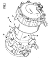
- the illustrated first embodiment of a compressor according to the invention for a gaseous medium, in particular a refrigerant, comprises a compressor housing, designated as a whole by 12, which has a first end housing section 14, a second end housing section 16 and one between the end housing sections 14 and 16 having arranged intermediate portion 18.
- a scroll compressor unit designated as a whole by 22, is provided in the first housing section 14, which has a first compressor body 24 arranged in a stationary manner in the compressor housing 12, in particular in the first housing section 14, as well as a second compressor body 26 movable relative to the stationary compressor body 24.
- the first compressor body 24 includes a compressor body base 32 above which a first spiral rib 34 rises
- the second compressor body 26 also includes a compressor body base 36 above which a second spiral rib 38 rises.
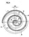
- the compressor bodies 24 and 26 are arranged relative to one another such that the spiral ribs 34, 38 intermesh around one another, as in FIG Fig. 4 shown to form between them at least one, preferably several compression chambers 42, in which a compression of the gaseous medium, for example refrigerant, takes place in that the second compressor body 26 with its central axis 46 around a central axis 44 of the first compressor body 24 on an orbital path 48 moves with a compressor orbital orbit radius VOR,
- the volume of the compression chambers 42 is reduced and compressed gaseous medium ultimately exits through a central outlet 52, while gaseous medium to be sucked in is sucked in through the circumferentially opening compressor chambers 42 on the radially outside relative to the central axis 44.
- the sealing of the compression chambers 42 relative to one another also takes place, in particular, in that the spiral ribs 34, 38 are provided with axial sealing elements 54 and 58 on the end face, which abut the respective bottom surface 62, 64 of the respective other compressor body 26, 24 in a sealing manner, the bottom surfaces 62 , 64 are formed by the respective compressor body base 36 or 32 and lie in a plane running perpendicular to the central axis 44.
- the scroll compressor unit 22 is received as a whole in a first housing body 72 of the compressor housing 12, which has an end cover section 74 and a cylindrical ring section 76 which is integrally formed on the end cover section 74 and which in turn engages with an annular shoulder 78 in a sleeve body 82 of the housing body 72, which is molded onto a central housing body 84 forming the intermediate section 18, the central housing body 84 being closed on a side opposite the first housing body 72 by a second housing body 86 which forms an inlet chamber 88 for the gaseous medium.
- the sleeve body 82 encloses the scroll compressor unit 22, the first compressor body 24 of which is supported on a contact surface 94 in the housing body 72 with support fingers 92 molded onto the compressor body base 32.
- the first compressor body 24 is fixed immovably in the housing body 72 against all movements parallel to the support surface 94.
- the first compressor body 24 is thus fixed in a stationary manner within the first housing body 72 and thus also within the compressor housing 12 in an exactly defined position.
- the axial guide 96 formed by a carrier element 112, which is made in particular from an open-pored sintered material and which has a carrier surface 114 facing the axial support surface 102, on which, however, the compressor body base 36 with the axial support surface 102 does not rest, but on which a whole with 116 designated, in particular plate-shaped sliding body 116 with a sliding support surface 118 rests, the sliding body 116 with a sliding support surface 122 opposite the sliding support surface 118 supporting the axial support surface 102 against movements parallel to the central axis 44 but slidingly guided with respect to movements transverse to the central axis 44.
- the axial guide 96 provides that when the second compressor body 26 moves on the orbital path 48 about the central axis 44 of the first compressor body 24, on the one hand the second compressor body 26 with the compressor body base 36 and its axial support surface 102 moves relative to the sliding body 116 , on the other hand the sliding body 116 in turn moves relative to the carrier element 118.
- sliding between the compressor body base 36 and the sliding body 116 takes place through a movement of the axial support surface 102 relative to the sliding support surface 122 of the sliding body 116 and, in addition, the sliding support surface 118 of the sliding body 116 is sliding relative to the carrier surface 114 of the carrier element 112.
- the sliding support surface 122 and the sliding support surface 118 of the sliding body 116 are provided with recesses, in particular micro-recesses, which form receptacles for a lubricant and contribute to the distribution of the lubricant.
- the sliding body 116 is provided with an in Fig. 7 and 8th
- the guide shown and designated as a whole by 132 is guided with play relative to the support element 112, the guide with play 132 comprising a guide recess 134 provided in the sliding body 116, which has a diameter DF, and a guide pin 136 anchored in the support element 112, the diameter of which DS is smaller than the diameter DF, so that half of the difference DF-DS defines a guide orbital radius with which the sliding body 116 can perform an orbiting movement relative to the carrier element 112.
- the guide orbital radius FOR is 0.01 times the compressor orbital radius or more, in particular 0.05 times the compressor orbital radius or more.
- the carrier element 112 is made of an aluminum alloy at least in the area of the carrier surface 114, improved lubrication is additionally ensured by the fact that lubricant enters the surface structures of the carrier element 112 provided, for example, and thus via the pores of the carrier element 112 Area of the support surface 114 is available for building up the lubricating film in the space.
- the sliding body 116 itself is designed as a plate-shaped, ring-shaped part made of spring steel and the sliding support surface 118 facing the carrier surface 114 is a smooth spring steel surface, the formation of the lubricating film is additionally promoted.
- the material pairing consisting of the aluminum alloy, which is softer than spring steel in the area of the support surface 114, and the spring steel in the area of the sliding support surface 118 has advantageous endurance properties due to its wear resistance.
- the carrier element 112 is provided not only with the carrier surface 114 on which the sliding body 116 rests, but also with the bearing surfaces 94 on which the support fingers 92 of the first compressor body 24 are supported.
- the carrier element 112 is also arranged in the housing body 72 so as to be fixed axially in the direction of the central axis 44 and against rotational movements about the central axis 44.
- the compressor body base 36 is in a radially inner edge region 152 and in a radially outer edge region 154 with an inclined relative to the axial support surface 102 and set back from the axial support surface 102
- Edge surface 156 or 158 is provided, which together with the sliding support surface 122 leads to a wedge-shaped space opening radially outward or radially inward, which facilitates the access of lubricant.
- the build-up of the lubricating film between the slide support surface 122 and the axial support surface 102 is promoted in that the slide support surface 122 and the axial support surface 102, in the overlap area in which they work together, are coherent, that is, in the circumferential direction U the central axis and annular surfaces 124 and 126, which are uninterrupted in their entire radial extent, are formed, in particular the annular surface 126 of the axial support surface 102 extending from an inner contour IK with a radius IR of the same to an outer contour AK, the radius IR being less than two-thirds of an outer radius AR is.
- annular surface 124 of the sliding support surface 122 is dimensioned in such a way that the annular surface 126 of the axial support surface 102 always rests on the sliding support surface 122 over its entire surface during all movements relative to the sliding support surface 122.
- the axial support surface 102 and the interacting with this sliding support surface 122 as well as the carrier surface 114 and the interacting with this sliding support surface 118 are all radially inward of a multiple coupling element sets 162 having coupling 164, which are at equal radial distances from the central axis 44 and at equal angular distances in the direction of rotation U are arranged around the central axis 44 and together form a coupling 164 which prevents the second movable compressor body 26 from rotating itself.
- the second coupling element 182 is formed by an annular body 184, which has a cylindrical inner surface 186 and a cylindrical outer surface 188, which are arranged coaxially to one another.
- This second coupling element 182 is guided in a third coupling element 192, which is designed as a receptacle 194 provided in the carrier element 112 for the ring body 184 and which has a cylindrical inner wall surface 196.
- a diameter DI of the inner wall surface 196 is greater than a diameter DRA of the cylindrical outer surface 188 of the ring body 184 and a diameter DRI of the cylindrical inner surface 186 is necessarily smaller than the diameter DRA of the cylindrical outer surface 188 of the ring body 184, with the diameter DRI of the cylindrical Inner surface 186 is larger than a diameter DSK of the cylindrical outer surface 176 of the pin body 174.
- each coupling element set 162 in turn forms an orbital guide whose maximum orbital radius OR for the orbiting movement corresponds to DI / 2- (DRA-DRI) / 2-DSK / 2.
- the movable compressor body 26 is guided relative to the stationary compressor body 24 by the coupling 164 in such a way that that in each case one of the coupling element sets 162 is effective in order to prevent the self-rotation of the second movable compressor body 26, whereby, for example, with six coupling element sets 162 after passing through an angular range of 60 °, the effectiveness of each coupling element set 162 from one coupling element set 162 to the next following coupling element set 162 in the direction of rotation changes.
- each coupling element set 162 has three coupling elements 172, 182 and 192 and in particular an annular body 184 is effective between the respective pin body 174 and the respective receptacle 194, on the one hand the wear resistance of the coupling element sets 162 is improved, on the other hand the lubrication in the area thereof is improved and, moreover, the generation of noise caused by the coupling element sets 162, which results from the change in the effectiveness of one coupling element set 162 to the other coupling element set 162.
- the coupling element sets 162 experience sufficient lubrication, in particular lubrication between the cylindrical outer surface 176 of the pin body 174 and the cylindrical inner surface 186 of the ring body 184 as well as lubrication between the cylindrical outer surface 188 of the ring body 184 and the cylindrical inner wall surface 196 of the Recording 194.
- the receptacles 194 in the carrier element 112 are open on both sides in the axial direction, the ring bodies 184 being held on their sides facing away from the second compressor body 26 by a stop element 198 protruding radially inward.
- openings 202, 204 are provided in the carrier element 112, which allow the passage of lubricant and sucked-in refrigerant.
- the compressor body base 36 is provided with star-shaped, radially outwardly extending projections 212 which engage in intermediate spaces 214 between support fingers 92 that follow one another in a direction of rotation U around the central axis 44, so that the coupling elements 172 also in these Interstices 214 lie and are thus arranged within the housing body 72 at the greatest possible radial distance from the central axis 44.
- This positioning of the coupling element sets 162, which is predetermined by the greatest possible radial distance between the coupling elements 172, at the greatest possible radial distance from the central axis 44, has the advantage that the forces acting on the coupling element sets 162 can be kept as small as possible due to the large lever arm , which has a beneficial effect on the component dimensioning.
- a flow of refrigerant and / or lubricant through the receptacles 194 is further facilitated by the fact that the extensions 212 have a recess 216 between the coupling elements 172 and the axial support surface 102.
- the inventive concept of the lubrication of the axial guide 96 and the coupling element sets 162 is particularly advantageous when the central axes 44 and 46 of the compressor bodies 24 and 26 normally run horizontally, i.e. at a maximum angle of 30 ° to a horizontal, with in the compressor housing 12, in particular in the area of the first housing body 72 at a point lowest in the direction of gravity, a lubricant bath 210 is formed, from which lubricant is whirled up during operation and taken up and distributed in the manner described.
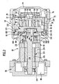
- the movable compressor body 24 is driven (as in Fig. 2 and 3rd shown) by a drive motor designated as a whole by 222, for example an electric motor, which in particular has a stator 224 held in the central housing body 84 and a rotor 226 arranged inside the stator 224, which is arranged on a drive shaft 228 which is coaxial with the central axis 44 of the stationary compressor body 24 runs.
- a drive motor designated as a whole by 222 for example an electric motor, which in particular has a stator 224 held in the central housing body 84 and a rotor 226 arranged inside the stator 224, which is arranged on a drive shaft 228 which is coaxial with the central axis 44 of the stationary compressor body 24 runs.
- the drive shaft 228 is mounted on the one hand in a compressor-facing bearing unit 232 arranged between the drive motor 222 and the scroll compressor unit 22 and in the central housing body 84, and on the other hand in a bearing unit 234 facing away from the compressor, which is arranged on a side of the drive motor 222 opposite the bearing unit 232.
- the bearing unit 234 facing away from the compressor is supported, for example, in the second housing body 86, which closes off the central housing body 84 on a side opposite the first housing body 72.
- the drive shaft 228 drives the movable compressor body 26 via an eccentric drive designated as a whole as 242, which moves orbiting about the central axis 44 of the stationary compressor body 24.
- the eccentric drive 242 comprises in particular an eccentric drive pin 244 held in the drive shaft 228, which moves a driver 246 on an orbital path around the central axis 44, which is rotatably mounted on the eccentric pin 244 and in turn is rotatably mounted in a pivot bearing 248, the pivot bearing 248 being a Rotation of the driver 246 relative to the movable compressor body 26 allowed.
- the driver 246 is rotatable to a limited extent relative to the eccentric pin 244 and relative to a driver receptacle 252 and enables the radius of the orbital movement of the movable compressor body 26 to be adjusted in order to keep the spiral ribs 34 and 38 in contact with one another.
- the second compressor body 26 is provided with the driver receptacle 252, which receives the rotary bearing 248.
- the driver receptacle 252 is set back relative to the flat side 98 of the compressor body base 36 and is thus arranged integrated in the compressor body base 36, so that the drive forces acting on the movable compressor body 26 are effective on a side of the flat side 98 of the compressor body base 36 facing the spiral rib 38 and thus drive the movable compressor body 26 with a low tilting moment, which is axially supported on the axial support surface 102 and guided transversely to the central axis 44 between the driver receptacle 252 and the drive motor 222 as seen through the axial guide 96 in the direction of the central axis 44.
- the driver receptacle 252 as in FIGS Fig. 2 , 3rd and 6 shown surrounded by the axial support surface 102 lying on the outside in the radial direction to the central axis 46 and the axial support surface 102 is in turn surrounded by the coupling element sets 162 of the clutch 164 which prevents the self-rotation of the second compressor body 26 and is on the outside in the radial direction to the central axis 44.
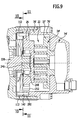
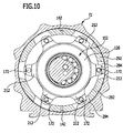
- the first stationary compressor body 24 'itself is not provided with the fingers 92, but its compressor body base 32' rests on the cover section 74 'radially within the ring section 76' and the ring shoulder 78 'is with Support fingers 292 are provided, which are supported on the carrier element 112 and connected in a rotationally fixed manner to the carrier element 112 by the positioning pins 142, which in this case engage in the support fingers 292.
- the compressor body base 36 is designed in the same way as in the first exemplary embodiment and, moreover, the coupling element sets 162 are also designed in the same way as in the first exemplary embodiment.
- the extensions 212 extend outward in the radial direction and engage in spaces 294 located between the support fingers 292, so that in this exemplary embodiment, too, there is the possibility of all the coupling element sets 162 of the self-rotation of the second compressor body 26 preventing clutch 164 to be arranged radially outside.
- FIG Fig. 12 In a third embodiment, shown in FIG Fig. 12 , those elements which are identical to those of the preceding exemplary embodiments are also provided with the same reference numerals, so that reference can be made to the statements relating to these exemplary embodiments.
- the extensions 212 of the compressor body base 36 of the second compressor body 26 are designed so that they receive the second coupling elements 182 of the coupling element sets 162, while the first coupling elements 172 of the coupling element sets 162 are in the compressor body base 32 ′′ of the first compressor body 24 are held and extend into the second coupling elements 182.
- the advantage of this exemplary embodiment can be seen in the fact that the coupling elements 172 and 182 cooperate in a plane of action WE which at the same time also intersects the pivot bearing 248 for the driver 246 and also intersects the extensions 212 of the compressor body base 36 ′′.
- the support effect of the coupling element sets 162 of the coupling 164 is thus improved even further and, in particular, the tendency of the orbiting compressor body 26 ′′ to tilt relative to the central axis 44 is reduced.
- the third exemplary embodiment enables a large degree of freedom with regard to the design and arrangement of the extensions 212 in the direction of the central axis 44, deviating from that in FIG Fig. 12 illustrated embodiment, so that they can be optimally arranged with regard to their position in the direction of the central axis 44 relative to the axial support surface 102 and to the spiral rib 38 of the second compressor body 26.
Landscapes
- Engineering & Computer Science (AREA)
- Mechanical Engineering (AREA)
- General Engineering & Computer Science (AREA)
- Rotary Pumps (AREA)
- Compressor (AREA)
- Applications Or Details Of Rotary Compressors (AREA)
Claims (15)
- Compresseur comprenant
un boîtier de compresseur (12),
une unité de compresseur hélicoïdal (22) disposée dans le boîtier de compresseur (12), avec un premier corps de compresseur (24) disposé de manière stationnaire et un deuxième corps de compresseur (26) pouvant être déplacé par rapport au corps de compresseur (24) disposé de manière stationnaire, dont les premières et deuxièmes nervures hélicoïdales (34, 38) réalisées sous la forme d'une développante de cercle s'imbriquent l'une dans l'autre en formant des chambres de compresseur (42) quand le deuxième corps de compresseur (26) est déplacé par rapport au premier corps de compresseur (24) sur une trajectoire orbitale (48) s'étendant autour d'un axe central (44) du corps de compresseur (24) disposé de manière stationna ire,
un guidage axial (96), lequel soutient le corps de compresseur (26) pouvant être déplacé pour empêcher des déplacements dans une direction parallèle par rapport à l'axe central (44) du corps de compresseur (24) disposé de manière stationnaire et mène lors de déplacements dans une direction transversale par rapport à l'axe central (44) de manière parallèle à un niveau s'étendant de manière perpendiculaire par rapport à l'axe central (44),
un entraînement excentrique (232) pour l'unité de compresseur hélicoïdal (22), qui présente un entraîneur (246) entraîné par un moteur d'entraînement (222) et s'étendant en périphérie sur une trajectoire autour de l'axe central (44), qui coopère quant à lui de manière rotative avec un logement d'entraînement (252) du deuxième corps de compresseur (26),
et un couplage (164) empêchant une rotation automatique du deuxième corps de compresseur (26), dans lequel le guidage axial (96) présente un élément de support (112), lequel fait office de base pour un soutien d'une base de corps de compresseur (36), supportant la nervure hélicoïdale (38), du deuxième corps de compresseur (26) au niveau d'une face d'appui axial (102), dans lequel la face d'appui axial (102) est disposée de manière à se situer à l'extérieur radialement par rapport à l'entraîneur (246), et
dans lequel le couplage (164) empêchant la rotation automatique présente au moins deux jeux d'éléments de couplage (162), qui comprennent quant à eux au moins deux éléments de couplage (172, 182, 192), et
dans lequel les jeux d'éléments de couplage (162) sont disposés de manière à se situer à l'extérieur radialement par rapport à la face d'appui axial (102),
caractérisé en ce que le deuxième corps de compresseur (26) est pourvu de prolongements (212) s'étendant vers l'extérieur de manière radiale par rapport à l'axe central (46) de celui-ci, au niveau desquels est maintenu respectivement un élément de couplage (172, 182) des jeux d'éléments de couplage (162), et que les prolongements (212) viennent en prise avec des espaces intermédiaires (214) disposés côté boîtier tout autour du deuxième corps de compresseur (26). - Compresseur selon la revendication 1, caractérisé en ce que la face d'appui axial (102) s'étend tout autour de l'entraîneur (246), qu'en particulier la face d'appui axial (102) est disposée de manière à se situer à l'extérieur radialement par rapport au logement d'entraîneur (242), qu'en particulier la face d'appui axial (102) est disposée de manière radiale dans le prolongement du logement d'entraîneur (242), et/ou qu'en particulier la face d'appui axial (102) est disposée sur un côté, opposé à la nervure hélicoïdale (38), du logement d'entraîneur (242).
- Compresseur selon la revendication 1 ou 2, caractérisé en ce que la face d'appui axial (102) comprend une zone de face annulaire (126) s'étendant en périphérie autour d'un axe central (46) du deuxième corps de compresseur (26), qu'en particulier la zone de face annulaire (126) est réalisée en tant qu'une face s'étendant de manière fermée et en continu dans une direction périphérique (U) autour de l'axe central (46), qu'en particulier la zone de face annulaire (126) s'étend de manière fermée dans une direction radiale par rapport à l'axe central (46) du deuxième corps de compresseur (26) et en continu depuis un contour intérieur (IK) jusqu'à un contour extérieur (AK), et/ou qu'en particulier un rayon (IR) du contour intérieur (IK) est inférieur aux deux tiers d'un rayon (AR) du contour extérieur (AK) de la zone de face annulaire (126), et/ou qu'en particulier la zone de face annulaire (126) de la face d'appui axial (102) comprend au moins 80 % de la totalité de la face de la face d'appui axial (102).
- Compresseur selon l'une quelconque des revendications précédentes, caractérisé en ce que la face d'appui axial (102) repose de manière transversale par rapport à l'axe central (46) de manière glissante sur un corps glissant (116), qui est soutenu quant à lui de manière transversale par rapport à l'axe central (46) de manière glissante sur un élément de support (112) disposé dans le boîtier de compresseur (12), qu'en particulier le corps glissant (116) peut être déplacé de manière bidimensionnelle par rapport à la base de corps de compresseur (36) et par rapport à l'élément de support (112), et/ou qu'en particulier le corps glissant (116) est guidé de manière à pouvoir être déplacé par un guidage bidimensionnel avec du jeu (132) par rapport à la base de corps de compresseur (36) et/ou par rapport à l'élément de support (112), et/ou qu'en particulier la face d'appui axial (102) prend appui sur une face annulaire, s'étendant en périphérie autour de l'axe central (44) du premier corps de compresseur (24), du corps glissant (116), et/ou qu'en particulier la face annulaire (124) du corps glissant (116) est réalisée de manière à s'étendre de manière fermée et en continu dans une direction périphérique autour de l'axe central (44) du premier corps de compresseur (24), et/ou qu'en particulier se situe dans le prolongement de la face d'appui axial (102) en étant située à l'intérieur ou à l'extérieur radialement une face de bord (154) de la deuxième base de corps de compresseur (36), qui s'étend en retrait par rapport à un plan, dans lequel s'étend la face d'appui axial (102), et/ou qu'en particulier le corps glissant (116) prend appui par une face de contact glissant (118) au niveau de l'élément de support (112), et/ou qu'en particulier l'élément de support (112) présente une face de support (114), sur laquelle le corps glissant (116) prend appui avec la face de contact glissant (118), et/ou qu'en particulier le corps glissant (116) est réalisé en forme de plaque, en particulier en tant que disque annulaire.
- Compresseur selon l'une quelconque des revendications précédentes, caractérisé en ce que les prolongements (212) sont maintenus au niveau d'une base de corps de compresseur (36) du deuxième corps de compresseur (26).
- Compresseur selon l'une quelconque des revendications précédentes, caractérisé en ce que les prolongements (212) sont formés d'un seul tenant au niveau de la base de corps de compresseur (36).
- Compresseur selon l'une quelconque des revendications précédentes, caractérisé en ce que le premier corps de compresseur (24) est positionné en direction de son axe central (44) et en particulier est soutenu ce faisant par des doigts d'appui (92, 292) par rapport à l'élément de support (112), et/ou qu'en particulier les espaces intermédiaires (214) se situent entre les doigts d'appui (92, 292) supportant le premier corps de compresseur (24).
- Compresseur selon l'une quelconque des revendications précédentes, caractérisé en ce que le premier corps de compresseur (24) est fixé de manière solidaire en rotation par les doigts d'appui (92, 292) par rapport à l'élément de support (112) pour empêcher une rotation autour de son axe central (44).
- Compresseur selon l'une quelconque des revendications précédentes, caractérisé en ce que la face d'appui axial (102) est formée elle-même par la base de corps de compresseur (36), supportant la nervure hélicoïdale (38), du deuxième corps de compresseur (26), que le guidage axial (96) soutient de manière glissante le deuxième corps de compresseur (26) au niveau de ladite face d'appui axial (102) de manière transversale par rapport à l'axe central (44), qu'en particulier le logement d'entraîneur (242) est intégré dans la base de corps de compresseur (36), qu'en particulier le logement d'entraîneur (242) est disposé dans une direction parallèle par rapport à l'axe central (44) sans saillie par rapport à la face de soutien (102) au niveau de la base de corps de compresseur (36).
- Compresseur selon l'une quelconque des revendications précédentes, caractérisé en ce que le couplage (164) empêchant la rotation automatique présente plus de deux jeux d'éléments de couplage (162), qu'en particulier les jeux d'éléments de couplage (162) sont disposés tout autour de l'axe central (44) de la trajectoire orbitale (48) à des espacements angulaires identiques, et qu'en particulier un des éléments de couplage (172) du jeu d'éléments de couplage (162) respectif est maintenu au niveau de la base de corps de compresseur (36).
- Compresseur selon l'une quelconque des revendications précédentes, caractérisé en ce qu'un des éléments de couplage (192) est maintenu au niveau de l'élément de support (112), qu'en particulier un (172) des éléments de couplage du jeu d'éléments de couplage respectif est formé par un corps de tige (174), qu'en particulier l'autre (192) des éléments de couplage du jeu d'éléments de couplage respectif est réalisé en tant que logement cylindrique (194).
- Compresseur selon l'une quelconque des revendications précédentes, caractérisé en ce qu'un (182) des éléments de couplage du jeu d'éléments de couplage respectif est réalisé en tant que corps annulaire (184) disposé dans le logement cylindrique (194).
- Compresseur selon la revendication 12, caractérisé en ce que le corps annulaire (184) siège de manière lâche dans le logement cylindrique (194).
- Compresseur selon l'une quelconque des revendications précédentes, caractérisé en ce que l'axe central (44) du corps de compresseur (24) stationnaire s'étend à l'horizontale.
- Compresseur selon l'une quelconque des revendications précédentes, caractérisé en ce qu'un arbre d'entraînement (218) du moteur d'entraînement (22) s'étend à l'horizontale.
Applications Claiming Priority (1)
| Application Number | Priority Date | Filing Date | Title |
|---|---|---|---|
| PCT/EP2016/053943 WO2017144098A1 (fr) | 2016-02-25 | 2016-02-25 | Compresseur |
Publications (2)
| Publication Number | Publication Date |
|---|---|
| EP3420193A1 EP3420193A1 (fr) | 2019-01-02 |
| EP3420193B1 true EP3420193B1 (fr) | 2020-08-12 |
Family
ID=55451170
Family Applications (1)
| Application Number | Title | Priority Date | Filing Date |
|---|---|---|---|
| EP16707410.3A Active EP3420193B1 (fr) | 2016-02-25 | 2016-02-25 | Compresseur |
Country Status (4)
| Country | Link |
|---|---|
| US (1) | US11041386B2 (fr) |
| EP (1) | EP3420193B1 (fr) |
| CN (1) | CN108779675B (fr) |
| WO (1) | WO2017144098A1 (fr) |
Families Citing this family (1)
| Publication number | Priority date | Publication date | Assignee | Title |
|---|---|---|---|---|
| DE102019124516A1 (de) * | 2019-09-12 | 2021-03-18 | Hanon Systems | Positionieranordnung |
Family Cites Families (16)
| Publication number | Priority date | Publication date | Assignee | Title |
|---|---|---|---|---|
| JPH0726621B2 (ja) * | 1982-09-29 | 1995-03-29 | 株式会社日立製作所 | 無給油スクロ−ル流体機械 |
| JPS6278494A (ja) * | 1985-10-02 | 1987-04-10 | Hitachi Ltd | スクロ−ル流体機械 |
| US5407335A (en) * | 1986-08-22 | 1995-04-18 | Copeland Corporation | Non-orbiting scroll mounting arrangements for a scroll machine |
| JP3561929B2 (ja) * | 1993-08-23 | 2004-09-08 | 株式会社豊田自動織機 | スクロール型圧縮機 |
| EP0682181B1 (fr) * | 1994-03-15 | 1998-08-26 | Denso Corporation | Compresseur à spirales |
| JP4273807B2 (ja) * | 2003-03-31 | 2009-06-03 | 株式会社豊田自動織機 | 電動圧縮機 |
| JP2006097531A (ja) * | 2004-09-29 | 2006-04-13 | Anest Iwata Corp | スクロール流体機械における旋回スクロール |
| JP2007291879A (ja) * | 2006-04-21 | 2007-11-08 | Sanden Corp | スクロール型流体機械 |
| US20120308414A1 (en) * | 2010-09-16 | 2012-12-06 | Panasonic Corporation | Inverter-integrated electric compressor |
| US9523361B2 (en) * | 2011-01-11 | 2016-12-20 | Lg Electronics Inc. | Scroll compressor having back pressure chamber that operatively contains a discharge pressure and an intermediate pressure during different periods of time within a single compression cycle |
| KR101441928B1 (ko) * | 2012-03-07 | 2014-09-22 | 엘지전자 주식회사 | 횡형 스크롤 압축기 |
| KR101462941B1 (ko) * | 2012-03-07 | 2014-11-19 | 엘지전자 주식회사 | 횡형 스크롤 압축기 |
| JP6007737B2 (ja) * | 2012-11-13 | 2016-10-12 | 株式会社豊田自動織機 | スクロール型圧縮機 |
| JP6171601B2 (ja) * | 2013-06-12 | 2017-08-02 | 株式会社豊田自動織機 | スクロール型圧縮機の自転防止機構 |
| KR102177990B1 (ko) * | 2014-05-02 | 2020-11-12 | 엘지전자 주식회사 | 압축기 및 스크롤 압축기 |
| DE102014113435A1 (de) * | 2014-09-17 | 2016-03-17 | Bitzer Kühlmaschinenbau Gmbh | Kompressor |
-
2016
- 2016-02-25 EP EP16707410.3A patent/EP3420193B1/fr active Active
- 2016-02-25 WO PCT/EP2016/053943 patent/WO2017144098A1/fr not_active Ceased
- 2016-02-25 CN CN201680082607.6A patent/CN108779675B/zh active Active
-
2018
- 2018-08-22 US US16/108,771 patent/US11041386B2/en active Active
Non-Patent Citations (1)
| Title |
|---|
| None * |
Also Published As
| Publication number | Publication date |
|---|---|
| CN108779675B (zh) | 2021-05-11 |
| WO2017144098A1 (fr) | 2017-08-31 |
| CN108779675A (zh) | 2018-11-09 |
| US20180363464A1 (en) | 2018-12-20 |
| EP3420193A1 (fr) | 2019-01-02 |
| US11041386B2 (en) | 2021-06-22 |
Similar Documents
| Publication | Publication Date | Title |
|---|---|---|
| EP3540229B1 (fr) | Compresseur à spirales | |
| EP1078165B1 (fr) | Ensemble compresseur en spirale | |
| DE10124265B4 (de) | Pumpe | |
| EP0848165B1 (fr) | Pompe à engrenages internes | |
| DE2801206C2 (fr) | ||
| EP0167846B1 (fr) | Machine à piston rotatif à axe interne | |
| EP3491245B1 (fr) | Compresseur | |
| DE3015628A1 (de) | Drucklager/kopplungseinrichtung und damit ausgeruestete schneckenmaschine | |
| DE202009011312U1 (de) | Handwerkzeug mit einem Oszillationsantrieb | |
| DE2607104A1 (de) | Ein- oder mehrzylindrige maschine, insbesondere brennkraftmaschine | |
| DE3519244A1 (de) | Hydraulische maschine der spiralart | |
| EP0949419B1 (fr) | Pompe à engrenages internes | |
| WO2011064290A2 (fr) | Pompe à palettes | |
| EP3420193B1 (fr) | Compresseur | |
| EP3679250B1 (fr) | Compresseur à vis | |
| DE10124267B4 (de) | Hydraulisches Pressgerät | |
| WO2006097092A1 (fr) | Machine a piston rotatif | |
| DE2306225A1 (de) | Steuerungssystem fuer rotationsmaschine | |
| DE3922436C2 (fr) | ||
| DE3346519C2 (fr) | ||
| DE102016103315B4 (de) | Kompressor | |
| DE10028336C1 (de) | Axialkolbenmaschine | |
| DE2323314A1 (de) | Antriebseinheit, insbesondere zum bewegen von schiebedaechern, fensterscheiben und wischelementen an kraftfahrzeugen | |
| DE3744637A1 (de) | Drehkolbenverdichter | |
| EP1118773A2 (fr) | Pompe ou moteur à palettes |
Legal Events
| Date | Code | Title | Description |
|---|---|---|---|
| STAA | Information on the status of an ep patent application or granted ep patent |
Free format text: STATUS: THE INTERNATIONAL PUBLICATION HAS BEEN MADE |
|
| PUAI | Public reference made under article 153(3) epc to a published international application that has entered the european phase |
Free format text: ORIGINAL CODE: 0009012 |
|
| STAA | Information on the status of an ep patent application or granted ep patent |
Free format text: STATUS: REQUEST FOR EXAMINATION WAS MADE |
|
| 17P | Request for examination filed |
Effective date: 20180822 |
|
| AK | Designated contracting states |
Kind code of ref document: A1 Designated state(s): AL AT BE BG CH CY CZ DE DK EE ES FI FR GB GR HR HU IE IS IT LI LT LU LV MC MK MT NL NO PL PT RO RS SE SI SK SM TR |
|
| AX | Request for extension of the european patent |
Extension state: BA ME |
|
| RAP1 | Party data changed (applicant data changed or rights of an application transferred) |
Owner name: BITZER KUEHLMASCHINENBAU GMBH |
|
| DAV | Request for validation of the european patent (deleted) | ||
| DAX | Request for extension of the european patent (deleted) | ||
| GRAP | Despatch of communication of intention to grant a patent |
Free format text: ORIGINAL CODE: EPIDOSNIGR1 |
|
| STAA | Information on the status of an ep patent application or granted ep patent |
Free format text: STATUS: GRANT OF PATENT IS INTENDED |
|
| RAP1 | Party data changed (applicant data changed or rights of an application transferred) |
Owner name: BITZER KUEHLMASCHINENBAU GMBH |
|
| INTG | Intention to grant announced |
Effective date: 20190930 |
|
| GRAJ | Information related to disapproval of communication of intention to grant by the applicant or resumption of examination proceedings by the epo deleted |
Free format text: ORIGINAL CODE: EPIDOSDIGR1 |
|
| STAA | Information on the status of an ep patent application or granted ep patent |
Free format text: STATUS: REQUEST FOR EXAMINATION WAS MADE |
|
| GRAS | Grant fee paid |
Free format text: ORIGINAL CODE: EPIDOSNIGR3 |
|
| STAA | Information on the status of an ep patent application or granted ep patent |
Free format text: STATUS: GRANT OF PATENT IS INTENDED |
|
| GRAP | Despatch of communication of intention to grant a patent |
Free format text: ORIGINAL CODE: EPIDOSNIGR1 |
|
| INTC | Intention to grant announced (deleted) | ||
| INTG | Intention to grant announced |
Effective date: 20200226 |
|
| GRAA | (expected) grant |
Free format text: ORIGINAL CODE: 0009210 |
|
| STAA | Information on the status of an ep patent application or granted ep patent |
Free format text: STATUS: THE PATENT HAS BEEN GRANTED |
|
| AK | Designated contracting states |
Kind code of ref document: B1 Designated state(s): AL AT BE BG CH CY CZ DE DK EE ES FI FR GB GR HR HU IE IS IT LI LT LU LV MC MK MT NL NO PL PT RO RS SE SI SK SM TR |
|
| REG | Reference to a national code |
Ref country code: CH Ref legal event code: EP |
|
| REG | Reference to a national code |
Ref country code: DE Ref legal event code: R096 Ref document number: 502016010828 Country of ref document: DE |
|
| REG | Reference to a national code |
Ref country code: IE Ref legal event code: FG4D Free format text: LANGUAGE OF EP DOCUMENT: GERMAN |
|
| REG | Reference to a national code |
Ref country code: AT Ref legal event code: REF Ref document number: 1301731 Country of ref document: AT Kind code of ref document: T Effective date: 20200915 |
|
| REG | Reference to a national code |
Ref country code: LT Ref legal event code: MG4D |
|
| REG | Reference to a national code |
Ref country code: NL Ref legal event code: MP Effective date: 20200812 |
|
| PG25 | Lapsed in a contracting state [announced via postgrant information from national office to epo] |
Ref country code: BG Free format text: LAPSE BECAUSE OF FAILURE TO SUBMIT A TRANSLATION OF THE DESCRIPTION OR TO PAY THE FEE WITHIN THE PRESCRIBED TIME-LIMIT Effective date: 20201112 Ref country code: NO Free format text: LAPSE BECAUSE OF FAILURE TO SUBMIT A TRANSLATION OF THE DESCRIPTION OR TO PAY THE FEE WITHIN THE PRESCRIBED TIME-LIMIT Effective date: 20201112 Ref country code: SE Free format text: LAPSE BECAUSE OF FAILURE TO SUBMIT A TRANSLATION OF THE DESCRIPTION OR TO PAY THE FEE WITHIN THE PRESCRIBED TIME-LIMIT Effective date: 20200812 Ref country code: FI Free format text: LAPSE BECAUSE OF FAILURE TO SUBMIT A TRANSLATION OF THE DESCRIPTION OR TO PAY THE FEE WITHIN THE PRESCRIBED TIME-LIMIT Effective date: 20200812 Ref country code: GR Free format text: LAPSE BECAUSE OF FAILURE TO SUBMIT A TRANSLATION OF THE DESCRIPTION OR TO PAY THE FEE WITHIN THE PRESCRIBED TIME-LIMIT Effective date: 20201113 Ref country code: HR Free format text: LAPSE BECAUSE OF FAILURE TO SUBMIT A TRANSLATION OF THE DESCRIPTION OR TO PAY THE FEE WITHIN THE PRESCRIBED TIME-LIMIT Effective date: 20200812 Ref country code: LT Free format text: LAPSE BECAUSE OF FAILURE TO SUBMIT A TRANSLATION OF THE DESCRIPTION OR TO PAY THE FEE WITHIN THE PRESCRIBED TIME-LIMIT Effective date: 20200812 |
|
| PG25 | Lapsed in a contracting state [announced via postgrant information from national office to epo] |
Ref country code: IS Free format text: LAPSE BECAUSE OF FAILURE TO SUBMIT A TRANSLATION OF THE DESCRIPTION OR TO PAY THE FEE WITHIN THE PRESCRIBED TIME-LIMIT Effective date: 20201212 Ref country code: PL Free format text: LAPSE BECAUSE OF FAILURE TO SUBMIT A TRANSLATION OF THE DESCRIPTION OR TO PAY THE FEE WITHIN THE PRESCRIBED TIME-LIMIT Effective date: 20200812 Ref country code: LV Free format text: LAPSE BECAUSE OF FAILURE TO SUBMIT A TRANSLATION OF THE DESCRIPTION OR TO PAY THE FEE WITHIN THE PRESCRIBED TIME-LIMIT Effective date: 20200812 Ref country code: RS Free format text: LAPSE BECAUSE OF FAILURE TO SUBMIT A TRANSLATION OF THE DESCRIPTION OR TO PAY THE FEE WITHIN THE PRESCRIBED TIME-LIMIT Effective date: 20200812 Ref country code: NL Free format text: LAPSE BECAUSE OF FAILURE TO SUBMIT A TRANSLATION OF THE DESCRIPTION OR TO PAY THE FEE WITHIN THE PRESCRIBED TIME-LIMIT Effective date: 20200812 |
|
| PG25 | Lapsed in a contracting state [announced via postgrant information from national office to epo] |
Ref country code: DK Free format text: LAPSE BECAUSE OF FAILURE TO SUBMIT A TRANSLATION OF THE DESCRIPTION OR TO PAY THE FEE WITHIN THE PRESCRIBED TIME-LIMIT Effective date: 20200812 Ref country code: CZ Free format text: LAPSE BECAUSE OF FAILURE TO SUBMIT A TRANSLATION OF THE DESCRIPTION OR TO PAY THE FEE WITHIN THE PRESCRIBED TIME-LIMIT Effective date: 20200812 Ref country code: SM Free format text: LAPSE BECAUSE OF FAILURE TO SUBMIT A TRANSLATION OF THE DESCRIPTION OR TO PAY THE FEE WITHIN THE PRESCRIBED TIME-LIMIT Effective date: 20200812 Ref country code: RO Free format text: LAPSE BECAUSE OF FAILURE TO SUBMIT A TRANSLATION OF THE DESCRIPTION OR TO PAY THE FEE WITHIN THE PRESCRIBED TIME-LIMIT Effective date: 20200812 Ref country code: EE Free format text: LAPSE BECAUSE OF FAILURE TO SUBMIT A TRANSLATION OF THE DESCRIPTION OR TO PAY THE FEE WITHIN THE PRESCRIBED TIME-LIMIT Effective date: 20200812 |
|
| REG | Reference to a national code |
Ref country code: DE Ref legal event code: R097 Ref document number: 502016010828 Country of ref document: DE |
|
| PG25 | Lapsed in a contracting state [announced via postgrant information from national office to epo] |
Ref country code: ES Free format text: LAPSE BECAUSE OF FAILURE TO SUBMIT A TRANSLATION OF THE DESCRIPTION OR TO PAY THE FEE WITHIN THE PRESCRIBED TIME-LIMIT Effective date: 20200812 Ref country code: AL Free format text: LAPSE BECAUSE OF FAILURE TO SUBMIT A TRANSLATION OF THE DESCRIPTION OR TO PAY THE FEE WITHIN THE PRESCRIBED TIME-LIMIT Effective date: 20200812 |
|
| PLBE | No opposition filed within time limit |
Free format text: ORIGINAL CODE: 0009261 |
|
| STAA | Information on the status of an ep patent application or granted ep patent |
Free format text: STATUS: NO OPPOSITION FILED WITHIN TIME LIMIT |
|
| PG25 | Lapsed in a contracting state [announced via postgrant information from national office to epo] |
Ref country code: SK Free format text: LAPSE BECAUSE OF FAILURE TO SUBMIT A TRANSLATION OF THE DESCRIPTION OR TO PAY THE FEE WITHIN THE PRESCRIBED TIME-LIMIT Effective date: 20200812 |
|
| 26N | No opposition filed |
Effective date: 20210514 |
|
| PG25 | Lapsed in a contracting state [announced via postgrant information from national office to epo] |
Ref country code: SI Free format text: LAPSE BECAUSE OF FAILURE TO SUBMIT A TRANSLATION OF THE DESCRIPTION OR TO PAY THE FEE WITHIN THE PRESCRIBED TIME-LIMIT Effective date: 20200812 |
|
| PG25 | Lapsed in a contracting state [announced via postgrant information from national office to epo] |
Ref country code: MC Free format text: LAPSE BECAUSE OF FAILURE TO SUBMIT A TRANSLATION OF THE DESCRIPTION OR TO PAY THE FEE WITHIN THE PRESCRIBED TIME-LIMIT Effective date: 20200812 |
|
| REG | Reference to a national code |
Ref country code: BE Ref legal event code: MM Effective date: 20210228 |
|
| PG25 | Lapsed in a contracting state [announced via postgrant information from national office to epo] |
Ref country code: CH Free format text: LAPSE BECAUSE OF NON-PAYMENT OF DUE FEES Effective date: 20210228 Ref country code: LI Free format text: LAPSE BECAUSE OF NON-PAYMENT OF DUE FEES Effective date: 20210228 Ref country code: LU Free format text: LAPSE BECAUSE OF NON-PAYMENT OF DUE FEES Effective date: 20210225 |
|
| PG25 | Lapsed in a contracting state [announced via postgrant information from national office to epo] |
Ref country code: IE Free format text: LAPSE BECAUSE OF NON-PAYMENT OF DUE FEES Effective date: 20210225 |
|
| REG | Reference to a national code |
Ref country code: AT Ref legal event code: MM01 Ref document number: 1301731 Country of ref document: AT Kind code of ref document: T Effective date: 20210225 |
|
| PG25 | Lapsed in a contracting state [announced via postgrant information from national office to epo] |
Ref country code: AT Free format text: LAPSE BECAUSE OF NON-PAYMENT OF DUE FEES Effective date: 20210225 |
|
| PG25 | Lapsed in a contracting state [announced via postgrant information from national office to epo] |
Ref country code: BE Free format text: LAPSE BECAUSE OF NON-PAYMENT OF DUE FEES Effective date: 20210228 |
|
| PG25 | Lapsed in a contracting state [announced via postgrant information from national office to epo] |
Ref country code: PT Free format text: LAPSE BECAUSE OF FAILURE TO SUBMIT A TRANSLATION OF THE DESCRIPTION OR TO PAY THE FEE WITHIN THE PRESCRIBED TIME-LIMIT Effective date: 20201214 |
|
| P01 | Opt-out of the competence of the unified patent court (upc) registered |
Effective date: 20230517 |
|
| PG25 | Lapsed in a contracting state [announced via postgrant information from national office to epo] |
Ref country code: CY Free format text: LAPSE BECAUSE OF FAILURE TO SUBMIT A TRANSLATION OF THE DESCRIPTION OR TO PAY THE FEE WITHIN THE PRESCRIBED TIME-LIMIT Effective date: 20200812 |
|
| PG25 | Lapsed in a contracting state [announced via postgrant information from national office to epo] |
Ref country code: HU Free format text: LAPSE BECAUSE OF FAILURE TO SUBMIT A TRANSLATION OF THE DESCRIPTION OR TO PAY THE FEE WITHIN THE PRESCRIBED TIME-LIMIT; INVALID AB INITIO Effective date: 20160225 |
|
| PG25 | Lapsed in a contracting state [announced via postgrant information from national office to epo] |
Ref country code: MK Free format text: LAPSE BECAUSE OF FAILURE TO SUBMIT A TRANSLATION OF THE DESCRIPTION OR TO PAY THE FEE WITHIN THE PRESCRIBED TIME-LIMIT Effective date: 20200812 |
|
| PG25 | Lapsed in a contracting state [announced via postgrant information from national office to epo] |
Ref country code: TR Free format text: LAPSE BECAUSE OF FAILURE TO SUBMIT A TRANSLATION OF THE DESCRIPTION OR TO PAY THE FEE WITHIN THE PRESCRIBED TIME-LIMIT Effective date: 20200812 |
|
| PG25 | Lapsed in a contracting state [announced via postgrant information from national office to epo] |
Ref country code: MT Free format text: LAPSE BECAUSE OF FAILURE TO SUBMIT A TRANSLATION OF THE DESCRIPTION OR TO PAY THE FEE WITHIN THE PRESCRIBED TIME-LIMIT Effective date: 20200812 |
|
| PGFP | Annual fee paid to national office [announced via postgrant information from national office to epo] |
Ref country code: GB Payment date: 20260223 Year of fee payment: 11 |
|
| PGFP | Annual fee paid to national office [announced via postgrant information from national office to epo] |
Ref country code: DE Payment date: 20260220 Year of fee payment: 11 |
|
| PGFP | Annual fee paid to national office [announced via postgrant information from national office to epo] |
Ref country code: IT Payment date: 20260220 Year of fee payment: 11 |
|
| PGFP | Annual fee paid to national office [announced via postgrant information from national office to epo] |
Ref country code: FR Payment date: 20260227 Year of fee payment: 11 |