EP3420263B1 - Vorrichtung und verfahren zur erwärmung einer unterwasserrohrleitung - Google Patents
Vorrichtung und verfahren zur erwärmung einer unterwasserrohrleitung Download PDFInfo
- Publication number
- EP3420263B1 EP3420263B1 EP17755642.0A EP17755642A EP3420263B1 EP 3420263 B1 EP3420263 B1 EP 3420263B1 EP 17755642 A EP17755642 A EP 17755642A EP 3420263 B1 EP3420263 B1 EP 3420263B1
- Authority
- EP
- European Patent Office
- Prior art keywords
- pipeline
- deployment mechanism
- conductor
- actuation assembly
- operatively
- Prior art date
- Legal status (The legal status is an assumption and is not a legal conclusion. Google has not performed a legal analysis and makes no representation as to the accuracy of the status listed.)
- Not-in-force
Links
Images


Classifications
-
- F—MECHANICAL ENGINEERING; LIGHTING; HEATING; WEAPONS; BLASTING
- F16—ENGINEERING ELEMENTS AND UNITS; GENERAL MEASURES FOR PRODUCING AND MAINTAINING EFFECTIVE FUNCTIONING OF MACHINES OR INSTALLATIONS; THERMAL INSULATION IN GENERAL
- F16L—PIPES; JOINTS OR FITTINGS FOR PIPES; SUPPORTS FOR PIPES, CABLES OR PROTECTIVE TUBING; MEANS FOR THERMAL INSULATION IN GENERAL
- F16L53/00—Heating of pipes or pipe systems; Cooling of pipes or pipe systems
- F16L53/30—Heating of pipes or pipe systems
- F16L53/34—Heating of pipes or pipe systems using electric, magnetic or electromagnetic fields, e.g. induction, dielectric or microwave heating
-
- H—ELECTRICITY
- H02—GENERATION; CONVERSION OR DISTRIBUTION OF ELECTRIC POWER
- H02G—INSTALLATION OF ELECTRIC CABLES OR LINES, OR OF COMBINED OPTICAL AND ELECTRIC CABLES OR LINES
- H02G1/00—Methods or apparatus specially adapted for installing, maintaining, repairing or dismantling electric cables or lines
- H02G1/06—Methods or apparatus specially adapted for installing, maintaining, repairing or dismantling electric cables or lines for laying cables, e.g. laying apparatus on vehicle
- H02G1/10—Methods or apparatus specially adapted for installing, maintaining, repairing or dismantling electric cables or lines for laying cables, e.g. laying apparatus on vehicle in or under water
-
- H—ELECTRICITY
- H02—GENERATION; CONVERSION OR DISTRIBUTION OF ELECTRIC POWER
- H02G—INSTALLATION OF ELECTRIC CABLES OR LINES, OR OF COMBINED OPTICAL AND ELECTRIC CABLES OR LINES
- H02G9/00—Installations of electric cables or lines in or on the ground or water
- H02G9/02—Installations of electric cables or lines in or on the ground or water laid directly in or on the ground, river-bed or sea-bottom; Coverings therefor, e.g. tile
-
- H—ELECTRICITY
- H05—ELECTRIC TECHNIQUES NOT OTHERWISE PROVIDED FOR
- H05B—ELECTRIC HEATING; ELECTRIC LIGHT SOURCES NOT OTHERWISE PROVIDED FOR; CIRCUIT ARRANGEMENTS FOR ELECTRIC LIGHT SOURCES, IN GENERAL
- H05B6/00—Heating by electric, magnetic or electromagnetic fields
- H05B6/02—Induction heating
- H05B6/10—Induction heating apparatus, other than furnaces, for specific applications
- H05B6/101—Induction heating apparatus, other than furnaces, for specific applications for local heating of metal pieces
-
- H—ELECTRICITY
- H05—ELECTRIC TECHNIQUES NOT OTHERWISE PROVIDED FOR
- H05B—ELECTRIC HEATING; ELECTRIC LIGHT SOURCES NOT OTHERWISE PROVIDED FOR; CIRCUIT ARRANGEMENTS FOR ELECTRIC LIGHT SOURCES, IN GENERAL
- H05B6/00—Heating by electric, magnetic or electromagnetic fields
- H05B6/02—Induction heating
- H05B6/10—Induction heating apparatus, other than furnaces, for specific applications
- H05B6/105—Induction heating apparatus, other than furnaces, for specific applications using a susceptor
- H05B6/108—Induction heating apparatus, other than furnaces, for specific applications using a susceptor for heating a fluid
-
- H—ELECTRICITY
- H05—ELECTRIC TECHNIQUES NOT OTHERWISE PROVIDED FOR
- H05B—ELECTRIC HEATING; ELECTRIC LIGHT SOURCES NOT OTHERWISE PROVIDED FOR; CIRCUIT ARRANGEMENTS FOR ELECTRIC LIGHT SOURCES, IN GENERAL
- H05B6/00—Heating by electric, magnetic or electromagnetic fields
- H05B6/02—Induction heating
- H05B6/36—Coil arrangements
-
- H—ELECTRICITY
- H05—ELECTRIC TECHNIQUES NOT OTHERWISE PROVIDED FOR
- H05B—ELECTRIC HEATING; ELECTRIC LIGHT SOURCES NOT OTHERWISE PROVIDED FOR; CIRCUIT ARRANGEMENTS FOR ELECTRIC LIGHT SOURCES, IN GENERAL
- H05B2214/00—Aspects relating to resistive heating, induction heating and heating using microwaves, covered by groups H05B3/00, H05B6/00
- H05B2214/03—Heating of hydrocarbons
-
- H—ELECTRICITY
- H05—ELECTRIC TECHNIQUES NOT OTHERWISE PROVIDED FOR
- H05B—ELECTRIC HEATING; ELECTRIC LIGHT SOURCES NOT OTHERWISE PROVIDED FOR; CIRCUIT ARRANGEMENTS FOR ELECTRIC LIGHT SOURCES, IN GENERAL
- H05B6/00—Heating by electric, magnetic or electromagnetic fields
- H05B6/02—Induction heating
- H05B6/36—Coil arrangements
- H05B6/365—Coil arrangements using supplementary conductive or ferromagnetic pieces
Definitions
- paraffins can form blockages in pipelines by building up on the inner diameter of the cold pipelines as relatively warm hydrocarbon fluid circulates out of a well and cools as it flows down a subsea pipeline. As the layer of paraffin builds up on the subsea pipeline inner diameter, the inner diameter of the paraffin becomes smaller and smaller. Ultimately a pigging device intended to clean the paraffin will cause the paraffin to separate from the inner wall of the pipeline and become a plug. In some cases the paraffin will release from the subsea pipeline inner diameter without a pig and cause a blockage. In either case, if the pressure in the pipeline is enough to move the plug along the pipeline, it will continue to collect additional paraffin as it moves until the length of the blockage cannot be moved by the available pressure.
- ROV remotely operated vehicle
- the electrical power source includes a controller to monitor and automatically control a temperature induced within the portion of pipeline.
- the electrical conductor has sufficient length so that the electrical power source may be located remotely from the deployment mechanism in order to facilitate subsea deployment thereof.
- the plurality of slats of the slatted framework includes a plurality of interconnecting biasing members for operatively tensioning the slats about the portion of pipeline.
- the biasing members may include spring members, or the like.
- the slatted framework may be under tension from the biasing members with deployment wires for releasing the tension in order to deploy the slats about the portion of pipeline.
- the deployment mechanism may include spacers arranged to operatively abut against the pipeline to maintain the conductor at a desired position relative to said pipeline.
- the actuation assembly may comprise four arms hinged together in a tongs-like framework arrangement for supporting the planar surface member.
- a method of heating a portion of a subsea pipeline comprising the steps of:
- the step of energising the conductor may comprise connecting a variable frequency, variable current and/or variable voltage electrical power source to the conductor.
- the step of deploying the conductor may comprise actuating at least two arms hinged together in a tongs-like arrangement and supporting said deployment mechanism therebetween from an open position (in which the deployment mechanism is suspended between the arms) to a closed position (in which the deployment mechanism urges the conductor about the portion of pipeline).
- a system for heating a portion of a subsea pipeline comprising:
- the surface vessel may comprise a spool for spooling a length of the conductor.
- the electrical conductor may comprise a variable frequency fluid-cooled induction lead.
- the electrical power supply may comprise a variable frequency, variable current and/or variable voltage power source.
- the deployment mechanism may include spacers arranged to operatively abut against the pipeline to maintain the conductor at a desired position relative to said pipeline.
- the actuation assembly may be remotely actuatable.
- the actuation assembly may be locally actuatable.
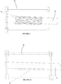
- the deployment mechanism may comprise a planar surface member on which the conductor is looped, said surface member configured to be flexible along a single axis.
- the primary framework comprises a displacement mechanism configured to displace the primary framework along a length of the pipeline.
- the system 42 generally comprises apparatus 20 and the variable frequency, variable current and/or variable voltage electrical power source 44 for operatively energising said conductor 22.
Landscapes
- Physics & Mathematics (AREA)
- Electromagnetism (AREA)
- Engineering & Computer Science (AREA)
- General Engineering & Computer Science (AREA)
- Mechanical Engineering (AREA)
- Earth Drilling (AREA)
- General Induction Heating (AREA)
Claims (15)
- Vorrichtung (20) zum Erwärmen eines Abschnitts einer Unterwasserrohrleitung (10), wobei die Vorrichtung (20) umfasst:mindestens einen elektrischen Leiter (26), gekennzeichnet dadurch, dass die Vorrichtung (20) ferner einen Entfaltungsmechanismus (24) umfasst, der konfiguriert ist, um eine Länge des elektrischen Leiters (26) in Schlaufenform betriebsmäßig zu tragen, wobei der Mechanismus (24) konfiguriert ist, um den geschlungenen Leiter in Umfangsrichtung um mindestens einen Abschnitt der Rohrleitung (10) zu entfalten, wodurch eine Schaltung gebildet wird;eine Betätigungsanordnung (36), die konfiguriert ist, um den Entfaltungsmechanismus (24) relativ zur Rohrleitung (10) betriebsmäßig zu positionieren und den Entfaltungsmechanismus (24) für die nachfolgende Entfaltung zu betätigen, wobei die Betätigungsanordnung (36) konfiguriert ist, um den Entfaltungsmechanismus (24) in mindestens zwei Ebenen im euklidischen Raum zu verschieben, um die gewünschte Positionierung des Entfaltungsmechanismus (24) relativ zur Rohrleitung (10) zu ermöglichen;eine elektrische Energieversorgung (44), die mit dem Leiter (22) betriebsmäßig verbunden ist, wobei die Versorgung (44) konfiguriert ist, um ein magnetisches Wechselfeld innerhalb der Schaltung betriebsmäßig zu induzieren, um Wärme in dem Abschnitt der Rohrleitung (10) durch Induktionserwärmung zu erzeugen; undeine Steuerung (52) zum Steuern der Energieversorgung (44) und konfiguriert zum automatischen Bestimmen und Aufrechterhalten einer Resonanzfrequenz in der Schaltung, indem eine kapazitive Reaktanz dynamisch eingestellt wird, um sie an eine induktive Reaktanz der Schaltung während des Erwärmens der Rohrleitung (10) anzupassen.
- Vorrichtung (20) nach Anspruch 1, wobei die elektrische Energieversorgung (44) eine Energiequelle mit variabler Frequenz, variablem Strom und/oder variabler Spannung umfasst.
- Vorrichtung (20) nach Anspruch 1, wobei die Steuerung (52) konfiguriert ist, um die Resonanzfrequenz der Schaltung automatisch zu bestimmen und aufrechtzuerhalten, indem periodisch eine Spannung angelegt wird, um einen Frequenzgang zu beobachten, um die Resonanz zu bestimmen und die kapazitive Reaktanz bei Bedarf einzustellen, um die induktive Reaktanz anzupassen.
- Vorrichtung (20) nach Anspruch 1, wobei der elektrische Leiter (26) eine ausreichende Länge aufweist, so dass die elektrische Energieversorgung (44) von dem Entfaltungsmechanismus (24) entfernt lokalisierbar ist, um dessen Unterwasser-Entfaltung zu erleichtern.
- Vorrichtung (20) nach Anspruch 1, wobei der Entfaltungsmechanismus (24) ein planares Oberflächenelement (28) umfasst, auf dem der Leiter (26) geschlungen ist, wobei das Oberflächenelement konfiguriert ist, um entlang einer einzelnen Achse flexibel zu sein.
- Vorrichtung (20) nach Anspruch 1, wobei der Entfaltungsmechanismus (24) Abstandshalter (34, 66) umfasst, die angeordnet sind, um betriebsmäßig an der Rohrleitung (10) anliegen, um den Leiter (26) an einer gewünschten Position relativ zu der Rohrleitung (10) zu halten.
- Vorrichtung (20) nach Anspruch 1, die eine Betätigungsanordnung (36) umfasst, die konfiguriert ist, um den Entfaltungsmechanismus (24) betriebsmäßig um den Abschnitt der Rohrleitung (10) zu treiben.
- Vorrichtung (20) nach Anspruch 1, wobei die Betätigungsanordnung (36) mindestens zwei Arme (38) umfasst, die in einer zangenartigen Anordnung miteinander angelenkt sind, die den Entfaltungsmechanismus (24) dazwischen trägt und zwischen einer offenen Position, in der der Entfaltungsmechanismus (24) zwischen den Armen (38) aufgehängt ist, und einer geschlossenen Position, in der der Entfaltungsmechanismus (24) die planare Oberfläche um den Abschnitt der Rohrleitung (10) treibt, betätigbar ist.
- Vorrichtung (20) nach Anspruch 1, wobei der Entfaltungsmechanismus (24) ein planares Oberflächenelement (28) umfasst, auf dem der Leiter (26) geschlungen ist, wobei das Oberflächenelement (28) konfiguriert ist, um entlang einer einzelnen Achse flexibel zu sein.
- Vorrichtung (20) nach Anspruch 1, wobei der Entfaltungsmechanismus (24) Abstandshalter (34, 66) umfasst, die angeordnet sind, um betriebsmäßig an der Rohrleitung (10) anliegen, um den Leiter (26) an einer gewünschten Position relativ zu der Rohrleitung (10) zu halten.
- Vorrichtung (20) nach Anspruch 1, wobei die Betätigungsanordnung (36) mindestens zwei Arme (38) umfasst, die in einer zangenartigen Anordnung miteinander angelenkt sind, die den Entfaltungsmechanismus (24) dazwischen trägt und zwischen einer offenen Position, in der der Entfaltungsmechanismus (24) zwischen den Armen aufgehängt ist, und einer geschlossenen Position, in der der Entfaltungsmechanismus (24) die planare Oberfläche um den Abschnitt der Rohrleitung (10) treibt, betätigbar ist.
- Vorrichtung (20) nach Anspruch 1, wobei die Betätigungsanordnung (36) ein primäres Gerüst umfasst, das ein verschachteltes sekundäres Gerüst darin trägt, wobei das sekundäre Gerüst den Entfaltungsmechanismus (24) trägt und relativ zum primären Gerüst verschiebbar angeordnet ist.
- Vorrichtung (20) nach Anspruch 12, wobei die Betätigungsanordnung (36) mindestens zwei Stellorgane umfasst, die konfiguriert sind, um das sekundäre Gerüst relativ zum primären Gerüst zu verschieben.
- Vorrichtung (20) nach Anspruch 12, wobei das Primärgerüst einen Verschiebungsmechanismus (24) umfasst, der konfiguriert ist, um das Primärgerüst entlang einer Länge der Rohrleitung (10) zu verschieben.
- Vorrichtung (20) nach Anspruch 12, wobei das Primärgerüst die Rohrleitung (10) mit dem Verschiebungsmechanismus überspannt, der eine Spuranordnung auf jeder Seite der Rohrleitung (10) umfasst.
Applications Claiming Priority (2)
| Application Number | Priority Date | Filing Date | Title |
|---|---|---|---|
| AU2016900670A AU2016900670A0 (en) | 2016-02-24 | Apparatus and method for heating subsea pipeline | |
| PCT/AU2017/050084 WO2017143389A1 (en) | 2016-02-24 | 2017-02-02 | Apparatus and method for heating subsea pipeline |
Publications (3)
| Publication Number | Publication Date |
|---|---|
| EP3420263A1 EP3420263A1 (de) | 2019-01-02 |
| EP3420263A4 EP3420263A4 (de) | 2019-10-30 |
| EP3420263B1 true EP3420263B1 (de) | 2020-07-22 |
Family
ID=57908602
Family Applications (1)
| Application Number | Title | Priority Date | Filing Date |
|---|---|---|---|
| EP17755642.0A Not-in-force EP3420263B1 (de) | 2016-02-24 | 2017-02-02 | Vorrichtung und verfahren zur erwärmung einer unterwasserrohrleitung |
Country Status (4)
| Country | Link |
|---|---|
| US (1) | US10247345B2 (de) |
| EP (1) | EP3420263B1 (de) |
| AU (1) | AU2016219627B1 (de) |
| WO (1) | WO2017143389A1 (de) |
Cited By (1)
| Publication number | Priority date | Publication date | Assignee | Title |
|---|---|---|---|---|
| US20240247747A1 (en) * | 2023-01-19 | 2024-07-25 | Salamander Ip Holdings Llc | Subsea pipeline remediation heating |
Families Citing this family (8)
| Publication number | Priority date | Publication date | Assignee | Title |
|---|---|---|---|---|
| US11231137B2 (en) * | 2018-05-14 | 2022-01-25 | Oceaneering International, Inc. | Subsea flowline blockage remediation using external heating device |
| EP3582328B1 (de) * | 2018-06-13 | 2021-03-17 | Nexans | Klemmvorrichtung und verfahren zur herstellung einer elektrischen verbindung zwischen einer unterwasserleitung und einem elektrischen leiter |
| BR112022019146A2 (pt) * | 2020-03-24 | 2022-11-08 | Totalenergies Onetech | Aparelho de aquecimento submarino para aquecer um componente submarino, conjunto de aquecimento submarino, sistema de aquecimento submarino, instalação de produção de petróleo e gás e método para fabricar um conjunto de aquecimento submarino |
| US12066139B1 (en) * | 2020-04-24 | 2024-08-20 | Allan Edwards, Incorporated | Pipe repair process |
| US20230265740A1 (en) * | 2020-07-13 | 2023-08-24 | Fmc Technologies Do Brasil Ltda | Subsea Induction Heating System and Related Method |
| NO347972B1 (en) * | 2023-03-07 | 2024-06-03 | Bang Andreasen Henrik | A stabilizing device for a subsea cable unit and a subsea system comprising a stabilizing device |
| US20240342765A1 (en) * | 2023-04-12 | 2024-10-17 | Salamander Ip Holdings Llc | Systems and Methods for Clearing Build-Up From Conduits |
| CN117613752B (zh) * | 2024-01-22 | 2024-05-03 | 广州珠江电缆集团(陕西)有限公司 | 一种便于低温环境下电缆施工安装的装置 |
Family Cites Families (12)
| Publication number | Priority date | Publication date | Assignee | Title |
|---|---|---|---|---|
| US4388510A (en) * | 1981-06-12 | 1983-06-14 | Commercial Resins Company | Heating collar with quadrafilar windings |
| US5186755A (en) * | 1990-05-29 | 1993-02-16 | Commercial Resins Company | Girth weld heating and coating system |
| US6278095B1 (en) * | 1999-08-03 | 2001-08-21 | Shell Oil Company | Induction heating for short segments of pipeline systems |
| US20080149343A1 (en) | 2001-08-19 | 2008-06-26 | Chitwood James E | High power umbilicals for electric flowline immersion heating of produced hydrocarbons |
| US7256374B2 (en) * | 2004-05-17 | 2007-08-14 | Colin Regan | Induction heating apparatus for controlling the welding parameter of temperature for heat treating a section of piping |
| US8115147B2 (en) * | 2005-06-03 | 2012-02-14 | Illinois Tool Works Inc. | Induction heating system output control based on induction heating device |
| US20130220996A1 (en) * | 2010-11-09 | 2013-08-29 | David John Liney | Induction heater system for electrically heated pipelines |
| US20130341320A1 (en) * | 2011-01-14 | 2013-12-26 | Shawcor Ltd. | Induction heating apparatus for pipeline connections |
| US20130098625A1 (en) * | 2011-10-24 | 2013-04-25 | Scott R. Hickman | Systems and Methods For Inductive Subsea Hydrocarbon Pipeline Heating For Pipeline Remediation |
| NO334151B1 (no) | 2012-02-17 | 2013-12-23 | Aker Subsea As | Havbunns varmesammenstilling og tilhørende fremgangsmåte |
| US9544950B2 (en) * | 2013-03-28 | 2017-01-10 | Inductotherm Heating & Welding Ltd | Electric induction heating and coating of the exterior surface of a pipe |
| US9521707B2 (en) * | 2013-04-09 | 2016-12-13 | Ptt Public Company Limited | Electromagnetic oil tank heating unit |
-
2016
- 2016-08-24 AU AU2016219627A patent/AU2016219627B1/en not_active Ceased
-
2017
- 2017-02-02 US US15/748,385 patent/US10247345B2/en active Active
- 2017-02-02 EP EP17755642.0A patent/EP3420263B1/de not_active Not-in-force
- 2017-02-02 WO PCT/AU2017/050084 patent/WO2017143389A1/en not_active Ceased
Non-Patent Citations (1)
| Title |
|---|
| None * |
Cited By (2)
| Publication number | Priority date | Publication date | Assignee | Title |
|---|---|---|---|---|
| US20240247747A1 (en) * | 2023-01-19 | 2024-07-25 | Salamander Ip Holdings Llc | Subsea pipeline remediation heating |
| US12578049B2 (en) * | 2023-01-19 | 2026-03-17 | Salamander Ip Holdings Llc | Subsea pipeline remediation heating |
Also Published As
| Publication number | Publication date |
|---|---|
| EP3420263A1 (de) | 2019-01-02 |
| US20190003629A1 (en) | 2019-01-03 |
| EP3420263A4 (de) | 2019-10-30 |
| WO2017143389A1 (en) | 2017-08-31 |
| US10247345B2 (en) | 2019-04-02 |
| AU2016219627B1 (en) | 2017-02-02 |
Similar Documents
| Publication | Publication Date | Title |
|---|---|---|
| EP3420263B1 (de) | Vorrichtung und verfahren zur erwärmung einer unterwasserrohrleitung | |
| US6142707A (en) | Direct electric pipeline heating | |
| US6264401B1 (en) | Method for enhancing the flow of heavy crudes through subsea pipelines | |
| CA2700735C (en) | Induction heaters used to heat subsurface formations | |
| US20120006444A1 (en) | Coiled umbilical tubing | |
| AU2016245945B2 (en) | Method of installing an electrically-heatable subsea flowline and electrically -heatable subsea flowline thereof | |
| CN103202096B (zh) | 用于电热管道的感应加热器系统 | |
| WO2010135772A1 (en) | Direct electric heating of subsea piping installations | |
| US20130118754A1 (en) | Thermal Hydrate Preventer | |
| BR112019008621B1 (pt) | Método e dispositivo para aquecimento por indução de um tubo interno de um conjunto de tubos coaxiais | |
| US20180339324A1 (en) | Electromagnetic induction heater | |
| CN104126092B (zh) | 水下加热组件及对水下部件进行加热的方法 | |
| AU2019394008B9 (en) | Heating of subsea pipelines | |
| AU2016305122B2 (en) | A method and a system for controlling the temperature of a fluid in an unbonded flexible pipe | |
| US9297253B2 (en) | Inductive connection | |
| US20180363823A1 (en) | Method of subsea pipeline blockage remediation | |
| WO2019222235A2 (en) | Subsea flowline blockage remediation using external heating device | |
| GB2407857A (en) | Pipe insulating apparatus and method | |
| Esaklul et al. | Active heating for flow assurance control in deepwater flowlines | |
| KR20150097476A (ko) | 시추 파이프의 유도 전단 | |
| Ahlen et al. | Electrical Induction heating system of subsea pipelines | |
| RU2204013C2 (ru) | Способ борьбы с гидратопарафиновыми образованиями и устройство для его осуществления | |
| BR102018011841B1 (pt) | Dispositivo para remoção de hidrato em equipamentos submarinos | |
| Silva et al. | Electrically heated pipe in pipe combined with electrical submersible pumps for deepwater development | |
| NO20150428A1 (en) | Installing Heated Subsea Pipelines |
Legal Events
| Date | Code | Title | Description |
|---|---|---|---|
| STAA | Information on the status of an ep patent application or granted ep patent |
Free format text: STATUS: THE INTERNATIONAL PUBLICATION HAS BEEN MADE |
|
| PUAI | Public reference made under article 153(3) epc to a published international application that has entered the european phase |
Free format text: ORIGINAL CODE: 0009012 |
|
| STAA | Information on the status of an ep patent application or granted ep patent |
Free format text: STATUS: REQUEST FOR EXAMINATION WAS MADE |
|
| 17P | Request for examination filed |
Effective date: 20180912 |
|
| AK | Designated contracting states |
Kind code of ref document: A1 Designated state(s): AL AT BE BG CH CY CZ DE DK EE ES FI FR GB GR HR HU IE IS IT LI LT LU LV MC MK MT NL NO PL PT RO RS SE SI SK SM TR |
|
| AX | Request for extension of the european patent |
Extension state: BA ME |
|
| DAV | Request for validation of the european patent (deleted) | ||
| DAX | Request for extension of the european patent (deleted) | ||
| A4 | Supplementary search report drawn up and despatched |
Effective date: 20190927 |
|
| RIC1 | Information provided on ipc code assigned before grant |
Ipc: H05B 6/10 20060101ALI20190923BHEP Ipc: F16L 53/00 20180101AFI20190923BHEP Ipc: H05B 6/36 20060101ALI20190923BHEP Ipc: H05B 6/02 20060101ALI20190923BHEP Ipc: F16L 53/34 20180101ALI20190923BHEP Ipc: H02G 1/10 20060101ALI20190923BHEP |
|
| GRAP | Despatch of communication of intention to grant a patent |
Free format text: ORIGINAL CODE: EPIDOSNIGR1 |
|
| STAA | Information on the status of an ep patent application or granted ep patent |
Free format text: STATUS: GRANT OF PATENT IS INTENDED |
|
| INTG | Intention to grant announced |
Effective date: 20200210 |
|
| GRAS | Grant fee paid |
Free format text: ORIGINAL CODE: EPIDOSNIGR3 |
|
| GRAA | (expected) grant |
Free format text: ORIGINAL CODE: 0009210 |
|
| STAA | Information on the status of an ep patent application or granted ep patent |
Free format text: STATUS: THE PATENT HAS BEEN GRANTED |
|
| AK | Designated contracting states |
Kind code of ref document: B1 Designated state(s): AL AT BE BG CH CY CZ DE DK EE ES FI FR GB GR HR HU IE IS IT LI LT LU LV MC MK MT NL NO PL PT RO RS SE SI SK SM TR |
|
| REG | Reference to a national code |
Ref country code: GB Ref legal event code: FG4D |
|
| REG | Reference to a national code |
Ref country code: CH Ref legal event code: EP |
|
| REG | Reference to a national code |
Ref country code: DE Ref legal event code: R096 Ref document number: 602017020239 Country of ref document: DE |
|
| REG | Reference to a national code |
Ref country code: AT Ref legal event code: REF Ref document number: 1293716 Country of ref document: AT Kind code of ref document: T Effective date: 20200815 |
|
| REG | Reference to a national code |
Ref country code: IE Ref legal event code: FG4D |
|
| REG | Reference to a national code |
Ref country code: NO Ref legal event code: T2 Effective date: 20200722 |
|
| REG | Reference to a national code |
Ref country code: LT Ref legal event code: MG4D |
|
| REG | Reference to a national code |
Ref country code: AT Ref legal event code: MK05 Ref document number: 1293716 Country of ref document: AT Kind code of ref document: T Effective date: 20200722 |
|
| PG25 | Lapsed in a contracting state [announced via postgrant information from national office to epo] |
Ref country code: HR Free format text: LAPSE BECAUSE OF FAILURE TO SUBMIT A TRANSLATION OF THE DESCRIPTION OR TO PAY THE FEE WITHIN THE PRESCRIBED TIME-LIMIT Effective date: 20200722 Ref country code: SE Free format text: LAPSE BECAUSE OF FAILURE TO SUBMIT A TRANSLATION OF THE DESCRIPTION OR TO PAY THE FEE WITHIN THE PRESCRIBED TIME-LIMIT Effective date: 20200722 Ref country code: BG Free format text: LAPSE BECAUSE OF FAILURE TO SUBMIT A TRANSLATION OF THE DESCRIPTION OR TO PAY THE FEE WITHIN THE PRESCRIBED TIME-LIMIT Effective date: 20201022 Ref country code: ES Free format text: LAPSE BECAUSE OF FAILURE TO SUBMIT A TRANSLATION OF THE DESCRIPTION OR TO PAY THE FEE WITHIN THE PRESCRIBED TIME-LIMIT Effective date: 20200722 Ref country code: GR Free format text: LAPSE BECAUSE OF FAILURE TO SUBMIT A TRANSLATION OF THE DESCRIPTION OR TO PAY THE FEE WITHIN THE PRESCRIBED TIME-LIMIT Effective date: 20201023 Ref country code: AT Free format text: LAPSE BECAUSE OF FAILURE TO SUBMIT A TRANSLATION OF THE DESCRIPTION OR TO PAY THE FEE WITHIN THE PRESCRIBED TIME-LIMIT Effective date: 20200722 Ref country code: PT Free format text: LAPSE BECAUSE OF FAILURE TO SUBMIT A TRANSLATION OF THE DESCRIPTION OR TO PAY THE FEE WITHIN THE PRESCRIBED TIME-LIMIT Effective date: 20201123 Ref country code: LT Free format text: LAPSE BECAUSE OF FAILURE TO SUBMIT A TRANSLATION OF THE DESCRIPTION OR TO PAY THE FEE WITHIN THE PRESCRIBED TIME-LIMIT Effective date: 20200722 Ref country code: FI Free format text: LAPSE BECAUSE OF FAILURE TO SUBMIT A TRANSLATION OF THE DESCRIPTION OR TO PAY THE FEE WITHIN THE PRESCRIBED TIME-LIMIT Effective date: 20200722 |
|
| PG25 | Lapsed in a contracting state [announced via postgrant information from national office to epo] |
Ref country code: IS Free format text: LAPSE BECAUSE OF FAILURE TO SUBMIT A TRANSLATION OF THE DESCRIPTION OR TO PAY THE FEE WITHIN THE PRESCRIBED TIME-LIMIT Effective date: 20201122 Ref country code: LV Free format text: LAPSE BECAUSE OF FAILURE TO SUBMIT A TRANSLATION OF THE DESCRIPTION OR TO PAY THE FEE WITHIN THE PRESCRIBED TIME-LIMIT Effective date: 20200722 Ref country code: RS Free format text: LAPSE BECAUSE OF FAILURE TO SUBMIT A TRANSLATION OF THE DESCRIPTION OR TO PAY THE FEE WITHIN THE PRESCRIBED TIME-LIMIT Effective date: 20200722 Ref country code: PL Free format text: LAPSE BECAUSE OF FAILURE TO SUBMIT A TRANSLATION OF THE DESCRIPTION OR TO PAY THE FEE WITHIN THE PRESCRIBED TIME-LIMIT Effective date: 20200722 |
|
| PG25 | Lapsed in a contracting state [announced via postgrant information from national office to epo] |
Ref country code: NL Free format text: LAPSE BECAUSE OF FAILURE TO SUBMIT A TRANSLATION OF THE DESCRIPTION OR TO PAY THE FEE WITHIN THE PRESCRIBED TIME-LIMIT Effective date: 20200722 |
|
| REG | Reference to a national code |
Ref country code: DE Ref legal event code: R097 Ref document number: 602017020239 Country of ref document: DE |
|
| PG25 | Lapsed in a contracting state [announced via postgrant information from national office to epo] |
Ref country code: RO Free format text: LAPSE BECAUSE OF FAILURE TO SUBMIT A TRANSLATION OF THE DESCRIPTION OR TO PAY THE FEE WITHIN THE PRESCRIBED TIME-LIMIT Effective date: 20200722 Ref country code: DK Free format text: LAPSE BECAUSE OF FAILURE TO SUBMIT A TRANSLATION OF THE DESCRIPTION OR TO PAY THE FEE WITHIN THE PRESCRIBED TIME-LIMIT Effective date: 20200722 Ref country code: CZ Free format text: LAPSE BECAUSE OF FAILURE TO SUBMIT A TRANSLATION OF THE DESCRIPTION OR TO PAY THE FEE WITHIN THE PRESCRIBED TIME-LIMIT Effective date: 20200722 Ref country code: EE Free format text: LAPSE BECAUSE OF FAILURE TO SUBMIT A TRANSLATION OF THE DESCRIPTION OR TO PAY THE FEE WITHIN THE PRESCRIBED TIME-LIMIT Effective date: 20200722 Ref country code: SM Free format text: LAPSE BECAUSE OF FAILURE TO SUBMIT A TRANSLATION OF THE DESCRIPTION OR TO PAY THE FEE WITHIN THE PRESCRIBED TIME-LIMIT Effective date: 20200722 Ref country code: IT Free format text: LAPSE BECAUSE OF FAILURE TO SUBMIT A TRANSLATION OF THE DESCRIPTION OR TO PAY THE FEE WITHIN THE PRESCRIBED TIME-LIMIT Effective date: 20200722 |
|
| PLBE | No opposition filed within time limit |
Free format text: ORIGINAL CODE: 0009261 |
|
| STAA | Information on the status of an ep patent application or granted ep patent |
Free format text: STATUS: NO OPPOSITION FILED WITHIN TIME LIMIT |
|
| PG25 | Lapsed in a contracting state [announced via postgrant information from national office to epo] |
Ref country code: AL Free format text: LAPSE BECAUSE OF FAILURE TO SUBMIT A TRANSLATION OF THE DESCRIPTION OR TO PAY THE FEE WITHIN THE PRESCRIBED TIME-LIMIT Effective date: 20200722 |
|
| 26N | No opposition filed |
Effective date: 20210423 |
|
| PG25 | Lapsed in a contracting state [announced via postgrant information from national office to epo] |
Ref country code: SK Free format text: LAPSE BECAUSE OF FAILURE TO SUBMIT A TRANSLATION OF THE DESCRIPTION OR TO PAY THE FEE WITHIN THE PRESCRIBED TIME-LIMIT Effective date: 20200722 |
|
| PG25 | Lapsed in a contracting state [announced via postgrant information from national office to epo] |
Ref country code: SI Free format text: LAPSE BECAUSE OF FAILURE TO SUBMIT A TRANSLATION OF THE DESCRIPTION OR TO PAY THE FEE WITHIN THE PRESCRIBED TIME-LIMIT Effective date: 20200722 |
|
| REG | Reference to a national code |
Ref country code: DE Ref legal event code: R119 Ref document number: 602017020239 Country of ref document: DE |
|
| PG25 | Lapsed in a contracting state [announced via postgrant information from national office to epo] |
Ref country code: MC Free format text: LAPSE BECAUSE OF FAILURE TO SUBMIT A TRANSLATION OF THE DESCRIPTION OR TO PAY THE FEE WITHIN THE PRESCRIBED TIME-LIMIT Effective date: 20200722 |
|
| REG | Reference to a national code |
Ref country code: NL Ref legal event code: MP Effective date: 20200722 |
|
| REG | Reference to a national code |
Ref country code: BE Ref legal event code: MM Effective date: 20210228 |
|
| PG25 | Lapsed in a contracting state [announced via postgrant information from national office to epo] |
Ref country code: CH Free format text: LAPSE BECAUSE OF NON-PAYMENT OF DUE FEES Effective date: 20210228 Ref country code: LI Free format text: LAPSE BECAUSE OF NON-PAYMENT OF DUE FEES Effective date: 20210228 Ref country code: LU Free format text: LAPSE BECAUSE OF NON-PAYMENT OF DUE FEES Effective date: 20210202 |
|
| PG25 | Lapsed in a contracting state [announced via postgrant information from national office to epo] |
Ref country code: DE Free format text: LAPSE BECAUSE OF NON-PAYMENT OF DUE FEES Effective date: 20210901 Ref country code: IE Free format text: LAPSE BECAUSE OF NON-PAYMENT OF DUE FEES Effective date: 20210202 Ref country code: FR Free format text: LAPSE BECAUSE OF NON-PAYMENT OF DUE FEES Effective date: 20210228 |
|
| PG25 | Lapsed in a contracting state [announced via postgrant information from national office to epo] |
Ref country code: BE Free format text: LAPSE BECAUSE OF NON-PAYMENT OF DUE FEES Effective date: 20210228 |
|
| PGFP | Annual fee paid to national office [announced via postgrant information from national office to epo] |
Ref country code: NO Payment date: 20221228 Year of fee payment: 7 Ref country code: GB Payment date: 20221227 Year of fee payment: 7 |
|
| PG25 | Lapsed in a contracting state [announced via postgrant information from national office to epo] |
Ref country code: CY Free format text: LAPSE BECAUSE OF FAILURE TO SUBMIT A TRANSLATION OF THE DESCRIPTION OR TO PAY THE FEE WITHIN THE PRESCRIBED TIME-LIMIT Effective date: 20200722 |
|
| PG25 | Lapsed in a contracting state [announced via postgrant information from national office to epo] |
Ref country code: HU Free format text: LAPSE BECAUSE OF FAILURE TO SUBMIT A TRANSLATION OF THE DESCRIPTION OR TO PAY THE FEE WITHIN THE PRESCRIBED TIME-LIMIT; INVALID AB INITIO Effective date: 20170202 |
|
| PG25 | Lapsed in a contracting state [announced via postgrant information from national office to epo] |
Ref country code: MK Free format text: LAPSE BECAUSE OF FAILURE TO SUBMIT A TRANSLATION OF THE DESCRIPTION OR TO PAY THE FEE WITHIN THE PRESCRIBED TIME-LIMIT Effective date: 20200722 |
|
| PG25 | Lapsed in a contracting state [announced via postgrant information from national office to epo] |
Ref country code: MT Free format text: LAPSE BECAUSE OF FAILURE TO SUBMIT A TRANSLATION OF THE DESCRIPTION OR TO PAY THE FEE WITHIN THE PRESCRIBED TIME-LIMIT Effective date: 20200722 |
|
| GBPC | Gb: european patent ceased through non-payment of renewal fee |
Effective date: 20240202 |
|
| PG25 | Lapsed in a contracting state [announced via postgrant information from national office to epo] |
Ref country code: NO Free format text: LAPSE BECAUSE OF NON-PAYMENT OF DUE FEES Effective date: 20240229 |
|
| PG25 | Lapsed in a contracting state [announced via postgrant information from national office to epo] |
Ref country code: GB Free format text: LAPSE BECAUSE OF NON-PAYMENT OF DUE FEES Effective date: 20240202 |
|
| PG25 | Lapsed in a contracting state [announced via postgrant information from national office to epo] |
Ref country code: GB Free format text: LAPSE BECAUSE OF NON-PAYMENT OF DUE FEES Effective date: 20240202 |
|
| PG25 | Lapsed in a contracting state [announced via postgrant information from national office to epo] |
Ref country code: TR Free format text: LAPSE BECAUSE OF FAILURE TO SUBMIT A TRANSLATION OF THE DESCRIPTION OR TO PAY THE FEE WITHIN THE PRESCRIBED TIME-LIMIT Effective date: 20200722 |